Sentinel TDC Installation - Toro Media
Sentinel TDC Installation - Toro Media
Sentinel TDC Installation - Toro Media

Create successful ePaper yourself
Turn your PDF publications into a flip-book with our unique Google optimized e-Paper software.
WARNING<br />
HIGH<br />
VOLTAGE<br />
115V<br />
4<br />
M AP<br />
<strong>Sentinel</strong> Field Satellite Controller<br />
Metal Pedestal, Plastic Pedestal and Wall Mount Models<br />
<strong>Installation</strong> Instructions<br />
Important: For your protection and the safety of the product user, please comply with all Caution and Warning<br />
statements within this document. All installation practices must comply with all applicable national and/or local<br />
electrical and building codes and be performed by qualified personnel only.<br />
Introduction<br />
The metal or plastic pedestal-mount satellite controller unit is designed for installation on a substantial concrete pad with<br />
embedded conduit of various diameters to enable wiring connections for power, field, earth ground, sensor and optional<br />
external antenna. Pedestal anchor bolts and a steel bolt pattern template are supplied with the controller.<br />
The wall-mount satellite unit is designed for installation on a structurally-sound building wall. The stainless steel cabinet<br />
is moisture resistant and suitable for outdoor installation. The cabinet has upper and lower support attachments and is<br />
supplied with a mounting bracket which attaches directly to the wall. Refer to wall mount installation procedures on page 2.<br />
Additional materials required to complete the installation must be obtained separately. A material list can be compiled by<br />
reading through the instructions completely prior to starting the installation.<br />
Metal Pedestal <strong>Installation</strong><br />
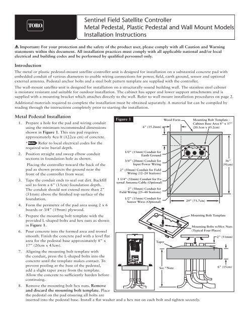
1. Prepare a hole for the pad and wiring conduit<br />
using the minimum recommended dimensions<br />
shown in Figure 1. This size pad requires<br />
approximately 4cu ft (122cu cm) of concrete.<br />
* Refer to local electrical codes for the<br />
required wire burial depth.<br />
2. Position straight and sweep elbow conduit<br />
sections in foundation hole as shown.<br />
Placing the controller toward the back of the<br />
pad as shown protects the ground near the<br />
front of the controller from wear.<br />
3. Tape the conduit ends to seal out dirt. Backfill<br />
soil to form a 6” (15cm) foundation depth.<br />
The conduit should not extend more than 2”<br />
(51mm) above the finished top surface of the<br />
foundation.<br />
4. Form the perimeter of the pad area using 2 x 6<br />
boards or 3/4” (19mm) plywood.<br />
5. Prepare the mounting bolt template with the<br />
provided L-shaped bolts and hex nuts as shown<br />
in Figure 1.<br />
6. Pour concrete into the formed area and trowel<br />
smooth. Finish the concrete pad with a level flat<br />
area for the pedestal base approximately 8” x<br />
17” (20cm x 43cm).<br />
7. Aligning the mounting bolt template with<br />
the conduit, press the L-shaped bolts into the<br />
concrete until the template makes contact. To<br />
prevent pooling at the base of the pedestal,<br />
add a slight taper away from the template.<br />
Allow the concrete to sufficiently harden before<br />
continuing.<br />
Figure 1<br />
6” (15.2mm)<br />
1/2” (13mm) Conduit for<br />
Earth Ground<br />
3/4” (20mm) Conduit for<br />
Input Power Wiring<br />
2” (50mm) Conduit for Field<br />
Wiring (12–24 Stations)<br />
1 1/4” (32mm) Conduit for External<br />
Antenna Cable (Optional)<br />
2” (50mm) Conduit for<br />
Field Wiring (25–48 Stations)<br />
1/2” (15mm) Conduit for<br />
Sensor Wires (Optional)<br />
Wood Form<br />
8. Remove the mounting bolt hex nuts. Remove<br />
and discard the mounting bolt template. Place<br />
the pedestal on the pad ensuring all bolts are<br />
inserted into the pedestal base. Install a flat washer and a hex nut on each bolt and tighten securely.<br />
Taper<br />
See *Note<br />
Mounting Bolt Template -<br />
Cabinet Base Area 8” x 17”<br />
(20.3cm x 43.2cm)<br />
29” (73.7cm)<br />
Mounting Bolt Template<br />
36”<br />
(91cm)<br />
Mounting Bolts w/Hex Nuts<br />
(Typical Four Places)<br />
2” (51mm)<br />
6” (15cm)
Plastic Pedestal <strong>Installation</strong><br />
1. Prepare a hole for the foundation and wiring<br />
conduit using the minimum recommended<br />
dimensions shown in Figure 2.<br />
* Refer to local electrical codes for<br />
required wire burial depth.<br />
Figure 2<br />
Wood Form<br />
Plastic Cabinet Base Area<br />
2. Trench to the foundation site as required for<br />
each wiring run.<br />
3. Position straight and sweep elbow conduit<br />
sections in foundation hole as shown. Tape<br />
the conduit ends to seal out dirt. Backfill soil<br />
to form a 6” (15.2cm) foundation depth.<br />
Conduit should not extend more than 2”<br />
(51mm) above the finished top surface of the<br />
foundation.<br />
4. Prepare the sides of the foundation hole with<br />
wood forms.<br />
5. Prepare the mounting bolt positioner with<br />
the 5/16 x 4-1/2” bolts and nuts (provided) as<br />
shown in Figure 2. The threads should extend<br />
2” (51mm) from the top surface of the bolt<br />
positioner.<br />
6. Pour concrete into the formed foundation<br />
hole. Press the mounting bolt positioner into<br />
the concrete until it is flush and level with<br />
the foundation surface and aligned with the<br />
conduit.<br />
Conduit Recommendations<br />
4” (10cm) - Field Stations<br />
1 1/2” (40mm) -<br />
External Antenna (Optional)<br />
3/4” (20mm) - Earth Ground<br />
3/4” (20mm) - Power Supply<br />
2” (50mm) Maximum<br />
Mounting Bolt<br />
Positioner<br />
6” (15cm)<br />
2”<br />
(50mm)<br />
30”<br />
(76cm)<br />
30”<br />
(76cm)<br />
Taper<br />
See *Note<br />
7. Finish the concrete with a level flat area of<br />
16” x 16” (41cm x 41cm) for the pedestal<br />
base. To prevent pooling at the base of the<br />
pedestal, add a slight taper away from the<br />
cabinet base contact area. Allow concrete to<br />
sufficiently harden before continuing.<br />
8. Remove the hex nuts from the mounting<br />
studs. Remove the cabinet cover and doors.<br />
Carefully position the controller onto the<br />
studs. Install a flat washer and a hex nut on<br />
each stud and tighten securely.
WARNING<br />
HIGH<br />
VOLTAGE<br />
115V<br />
4<br />
M AP<br />
PROGRAMMING INSTRUCTIONS<br />
OFF<br />
ON<br />
ESC<br />
ON<br />
YES<br />
CLUSTER /<br />
SCHEDULE<br />
SELECT<br />
PROGRAM<br />
SELECT<br />
ENTER<br />
Wall-Mount Cabinet <strong>Installation</strong><br />
1. Position the upper support bracket on the<br />
wall with the joggle edge up to accept the<br />
mating upper cabinet bracket. The support<br />
bracket must be level and at a height<br />
approximately 2” (51mm) above eye level to<br />
enable the <strong>Sentinel</strong> control module display to<br />
be easily viewed.<br />
2. Mark the two mounting screw hole locations<br />
and drill pilot holes for the screws or screw<br />
anchors.<br />
Use 3/8” (10mm) diameter fasteners<br />
to attach the cabinet support brackets. If<br />
installing the cabinet on dry wall or masonry,<br />
install the appropriate size and type screw<br />
anchors.<br />
3. Secure the support bracket to the wall. Hang<br />
the cabinet on the wall by engaging the upper<br />
cabinet bracket and the support bracket.<br />
4. Draw a pencil line the entire length of the<br />
lower support bracket.<br />
5. Remove the cabinet from the wall and remove<br />
the lower support bracket from the cabinet.<br />
6. Place the lower support bracket on the wall<br />
aligning it with the pencil mark.<br />
7. Mark the two screw hole locations and drill<br />
pilot holes for the mounting screws or screw<br />
anchors.<br />
8. Secure the bottom support bracket to the<br />
wall.<br />
* On early model cabinets, conduit<br />
access holes are only provided for power and<br />
one field wire conduit. Additional conduit<br />
access holes for earth ground, additional<br />
field wire conduit, optional sensor wires and<br />
optional external antenna must be cut or<br />
punched by the installer. All conduit access<br />
holes and knock-outs are provided on current<br />
production cabinets.<br />
9. Remove optional conduit knock-outs as<br />
required for installation. See *Note above.<br />
10. Hang the cabinet on the wall mount support<br />
bracket. The bottom edge of the cabinet<br />
should now rest squarely on the lower<br />
support bracket.<br />
11. Secure the cabinet to the lower support<br />
bracket using the carriage bolts and nuts<br />
removed in Step 5 above.<br />
12. Install electrical conduit for all wiring<br />
connections per local and national code. See<br />
Figure 4.<br />
Figure 3<br />
Figure 4<br />
3/4” (20mm)<br />
Conduit for<br />
Power Wires<br />
1/2” (15mm) Conduit<br />
for Earth Ground<br />
Screw Anchors<br />
1 2 3 F1<br />
4 5 6<br />
7 8 9<br />
0<br />
F2<br />
F3<br />
F4<br />
Upper Cabinet Bracket<br />
Upper Support Bracket<br />
Lower Support Bracket<br />
1/2” (15mm)<br />
Conduit for<br />
Sensor Wires<br />
(Optional)<br />
2” (50mm) Conduit for Field<br />
Wiring (25–48 Stations)<br />
2” (50mm) Conduit for Field<br />
Wiring (12–24 Stations)<br />
1 1/2” (40mm) Conduit for<br />
External Antenna (Optional)
Earth Ground <strong>Installation</strong><br />
IMPORTANT! The <strong>TDC</strong> surge protection components cannot properly function unless an efficient pathway to earth<br />
ground is provided. The ground path must be as direct as possible, without sharp bends and must not exceed 30 Ohm<br />
resistance (when measured with an earth ground resistance device). All electrical components throughout the irrigation system<br />
should be grounded similarly to provide the same ground potential.<br />
The following instructions depict one of several acceptable earth grounding methods. Due to variables in soil composition and<br />
terrain, the method shown may not be suitable for your installation site. Contact your local <strong>Toro</strong> distributor for assistance and<br />
availability of the required earth ground resistance test instrument.<br />
Step 1 –<br />
Step 2 –<br />
Step 3 –<br />
Drive a 5/8" x 8' (17mm x 2.5m) copper-clad steel rod into well moistened soil not less than 8' (2.5m) or not more<br />
than 12' (3.7m) from the controller cabinet. The top of the ground rod should be 12" (30.5cm) below grade level.<br />
See Figure 2.<br />
Using a 5/8" (17mm) clamp or “Cad weld” fastener, attach an 8 AWG (8mm 2 ) solid copper wire near the top of the<br />
ground rod. Avoiding wire bends of less than 8" (20.3cm) radius and more than 90 o , route the wire through conduit<br />
and into the cabinet. Secure the wire to the copper ground lug.<br />
Make sure the soil surrounding the ground rod(s) remains well moistened at all times. The addition of<br />
some form of irrigation may be required if the cabinet is installed in a non-irrigated location.<br />
Measure the ground resistance per the instructions provided with the ground test instrument. A reading of<br />
0.0 Ohm is optimum, up to 10 Ohm is good and 11–30 Ohm is acceptable in most cases. If the resistance exceeds<br />
the acceptable limit, additional ground rod(s) can be installed at a distance equal to twice the buried depth of the<br />
first rod; i.e., 16' (4.9m). Interconnect the ground rods using 8 AWG (8mm 2 ) solid copper wire and test again. If the<br />
measured ground resistance continues to read above the acceptable limit, contact your local <strong>Toro</strong> distributor for<br />
further assistance and recommendations.<br />
Installing a round valve box over the ground rod enables the ground rod to be easily located as well as<br />
providing access to the ground wire connection(s).<br />
Figure 2<br />
Ground Lug<br />
Valve Box<br />
8 AWG (8mm 2 )<br />
Solid Copper Ground Wire<br />
12" (30.5cm)<br />
8" (20.3cm)<br />
Minimum Radius<br />
Ground Wire To<br />
Additional Rod(s)<br />
(Optional)<br />
8'–12'<br />
(2.4m – 3.7m)<br />
Copper Clad<br />
Ground Rod<br />
90 o Minimum Angle
Power Source <strong>Installation</strong><br />
WARNING! AC POWER WIRING MUST BE INSTALLED AND CONNECTED BY QUALIFIED<br />
PERSONNEL ONLY.<br />
ALL ELECTRICAL COMPONENTS AND INSTALLATION PROCEDURES MUST COMPLY WITH ALL<br />
APPLICABLE LOCAL AND NATIONAL ELECTRICAL CODES. SOME CODES MAY REQUIRE A MEANS OF<br />
DISCONNECTION FROM THE AC POWER SOURCE, INSTALLED IN THE FIXED WIRING, HAVING A CONTACT<br />
SEPARATION OF AT LEAST 3mm IN THE LINE AND NEUTRAL POLES.<br />
ENSURE THE AC POWER SOURCE IS OFF PRIOR TO SERVICING. FAILURE TO COMPLY MAY RESULT IN SERIOUS<br />
INJURY DUE TO ELECTRICAL SHOCK HAZARD.<br />
Step 1 –<br />
Step 2 –<br />
Step 3 –<br />
Step 4 –<br />
Step 5 –<br />
Step 6 –<br />
Turn off the power at the power source location and<br />
place the controller’s power switch to OFF. Connect and<br />
route the appropriate size 3-conductor cable (10 AWG<br />
[2.5mm 2 ] maximum) from the power source to the<br />
controller cabinet.<br />
The provided power cable access hole can<br />
accommodate a 1" (25mm) conduit fitting. If conduit is<br />
required, install a section of flexible 1" (25mm) electrical<br />
conduit from the power source conduit box to the<br />
cabinet’s access hole.<br />
Open the cabinet door and remove the two retaining<br />
screws from the power supply cover.<br />
Locate the voltage cable assembly and note the voltage<br />
on the label. The <strong>TDC</strong> is equipped with 120V cable<br />
assembly from the factory. Replace the voltage cable<br />
assembly with the proper rating as necessary. See<br />
Figure 3.<br />
Strip the power cables and secure them to the terminal<br />
block. Reference Table 1 for the appropriate type of<br />
power connection.<br />
Reinstall the power supply cover.<br />
Apply power to the controller.<br />
Flexible Conduit<br />
(Optional)<br />
Voltage Cable<br />
Assembly<br />
Figure 3<br />
Line<br />
Neutral<br />
Equipment<br />
Ground
Station Decoder <strong>Installation</strong><br />
The station decoder module is available in 1-station, 2-station or 4-station configuration. The decoder modules are installed into<br />
the <strong>TDC</strong> output board terminals.<br />
The stand-alone <strong>TDC</strong> model can handle up to 100 stations per output board. These stations can be connected to the output<br />
board terminals in any configuration (25 stations connected to each of the four terminal pairs or 100 stations connected to one<br />
terminal pair, etc.). The decoder modules can be connected in parallel anywhere on the two-wire communication line connected<br />
to the station terminals. Each station can activate up to two solenoids.<br />
It is recommended that the decoder modules are installed in an approved valve box to provide easy access to the wiring. Use<br />
high-voltage waterproofing to all the wire connections.<br />
Recommended Controller-to-Decoder cable: 14 AWG (2.5mm 2 ), solid copper, jacketed 2-conductor, direct burial. The<br />
preferred wire make and model is the Paige Irrigation Wire, Spec P7350D.<br />
Recommended Decoder-to-Solenoid cable: 14 AWG (2.5mm 2 ), solid copper, 2-conductor, direct burial. The preferred wire<br />
make and model is the Paige Irrigation Wire, Spec P7351D.<br />
IMPORTANT!<br />
Cable Splices: In order for the wire connections to comply with the 2005 edition of the National Electric Code®<br />
Article 300.5 (Underground <strong>Installation</strong>s) and 110.14 (Electrical Connections), in wet or damp locations, the connector<br />
must be listed under specification “UL 486D” if installed in a valve box. It must be listed under specification “UL 486D-<br />
Direct Burial” if buried in dirt. This requirement applies to all electrical connections in wet or damp locations,<br />
regardless of voltage. The 3M DBY-6 and DBR-6 are listed as “UL 486D-Direct Burial” and meet these requirements for<br />
all underground installations.<br />
Cable Burial Depth: The <strong>TDC</strong> decoder operate at voltages between 30–40 volts. The 2005 edition of the National<br />
Electrical Code®, Article 300-5, requires that wires and cables subjected to voltages higher than 30 volts are to have a<br />
minimum cover of 24" (60.96 cm).<br />
• Use only wire approved for direct burial if installing the wires underground without conduit.<br />
• All field wiring splices must be accessible to facilitate troubleshooting and/or service.<br />
Step 1 – Route communication cable from the controller to the station decoder module installation location.<br />
The maximum wire length between the controller and the decoder module is 15,000' (4500m).<br />
Step 2 – Secure the communication wires to terminal 1 of the <strong>TDC</strong> output board. White wire onto the 1st terminal and black<br />
wire onto the second terminal. See Figure 4.<br />
Step 3 – Install the decoder module in a valve box. Record the decoder module’s address number found on the side label.<br />
This address number identifies the station(s) that the decoder module control.<br />
Step 4 – Secure the communication wires to the decoder module’s black and white wires. Connect the black communication<br />
wire to the black decoder module wire. Connect the remaining communication wire (red or white) to the white<br />
decoder module wire. Use proper water proofing method for all wire connections.<br />
Step 5 – Route output wires from the decoder module to the solenoid.<br />
The maximum wire length between the decoder module and the solenoid is 410' (125m).<br />
Step 6 – Connect the solenoid wires to the decoder module’s station wires. The station wires are color coded for easy<br />
identification. Connect the solid colored (red, green, orange or blue) station wire to the red/white solenoid wire.<br />
Connect the similar color station wire with black stripe to the black solenoid wire. Waterproof all wire connections.<br />
Step 7 – Connect an additional solenoid to the station wire as necessary.<br />
Each station has a maximum load of two solenoids.<br />
Step 8 – Repeat Steps 3–8 for additional decoder modules.
Figure 4<br />
DC Latching<br />
Solenoid<br />
Red<br />
White Power/Communication Wire<br />
Black Power/Communication Wire<br />
Black<br />
Station 1<br />
Solid Red Station Wire - Connect to the Red/White solenoid wire<br />
Red with Black Stripe Station Wire - Connect to the Black solenoid wire<br />
Station 2<br />
Solid Green Station Wire - Connect to the Red/White solenoid wire<br />
Green with Black Stripe Station Wire - Connect to the Black solenoid wire<br />
Station 3<br />
Solid Orange Station Wire - Connect to the Red/White solenoid wire<br />
Orange with Black Stripe Station Wire - Connect to the Black solenoid wire<br />
Station 4<br />
Solid Blue Station Wire - Connect to the Red/White solenoid wire<br />
Blue with Black Stripe Station Wire - Connect to the Black solenoid wire<br />
Each station can activate up<br />
to two DC Latching Solenoids.<br />
1-Station<br />
Decoder<br />
Module<br />
Output Board<br />
Station Wires<br />
The Stand-Alone <strong>TDC</strong> output board<br />
can accommodate up to 100 stations.<br />
The decoder modules can be<br />
connected in any configuration using<br />
the four station terminals.<br />
Out to additional<br />
decoder modules<br />
White<br />
Black<br />
White<br />
Black<br />
White<br />
Black<br />
White<br />
Black<br />
Paths – 1 2 3 4<br />
Valve Box<br />
The maximum communication wire length<br />
between the decoder module and the<br />
solenoid is 410ft (125m).<br />
Recommended Cable for Decoder-to-Solenoid<br />
is the Paige ® P7351D, 14 AWG, Solid Copper,<br />
2-Conductor, Direct Burial cable.<br />
To easily identify stations for<br />
troubleshooting, install wires with the same<br />
color code as the station wires.<br />
When possible, install the decoder<br />
module in a valve box for ease of service.<br />
Maximum communication wire length<br />
between the controller and the farthest<br />
decoder is 15,000ft (4500m).<br />
Recommended Cable for Controller-to-Decoder is the Paige ®<br />
P7350D, 14 AWG, Solid Copper, Jacketed 2-Conductor,<br />
Direct Burial cable.
Grounding Communication Cable<br />
IMPORTANT!<br />
Cable Splices: In order for the wire connections to comply with the 2005 edition of the National Electric Code®<br />
Article 300.5 (Underground <strong>Installation</strong>s) and 110.14 (Electrical Connections), in wet or damp locations, the connector<br />
must be listed under specification “UL 486D” if installed in a valve box. It must be listed under specification “UL 486D-<br />
Direct Burial” if buried in dirt. This requirement applies to all electrical connections in wet or damp locations,<br />
regardless of voltage. The 3M DBY-6 and DBR-6 are listed as “UL 486D-Direct Burial” and meet these requirements for<br />
all underground installations.<br />
Cable Burial Depth: The <strong>TDC</strong> decoder operate at voltages between 30–40 volts. The 2005 edition of the National<br />
Electrical Code®, Article 300-5, requires that wires and cables subjected to voltages higher than 30 volts are to have a<br />
minimum cover of 24" (60.96 cm).<br />
The optional lightning arrester (<strong>Toro</strong> P/N DEC-SG-LINE) is available to protect the decoder module in lightning prone areas.<br />
Without lightning arrester, the decoder are vulnerable to lightning damage. In order for these arrester to discharge lightning<br />
energy efficiently, they must be properly grounded. Figure 5 illustrates the proper grounding and wiring of the arrester.<br />
Step 1 –<br />
Step 2 –<br />
Step 3 –<br />
Step 4 –<br />
Step 5 –<br />
Step 6 –<br />
Locate decoder’s power/communication wires (black and white wires). Disconnect the wire connectors that joins it<br />
to the controller-to-decoder cable.<br />
Strip the insulation from lightning arrester’s white wire and connect it to the white wires from the decoder and<br />
controller-to-decoder cable. Secure the splices with a water proofed wire connector. (See Figure 5.)<br />
Strip the insulation from lightning arrester’s black wire and connect it to the black wires from the decoder and<br />
controller-to-decoder cable. Secure the splices with a water proofed wire connector. (See Figure 5.)<br />
Connect the lightning arrester’s ground wire to the ground plate’s wire. If the ground plate is not pre-wired, use a<br />
10 AWG bare copper wire. (See Figure 5.)<br />
IMPORTANT! Verify that the wire length between the lightning arrester and the ground plate is no less than<br />
3' (91.44 cm). Longer lengths will decrease the lightning arrester’s effectiveness.<br />
Bury the Ground plate next to the valve box or decoder’s location. Set it at the maximum depth that the ground<br />
wire would allow. Surround the ground plate with 50 lbs (2.68 Kg) of Earth contact material such as PowerSet ®<br />
(Paige Electric, part number 1820058).<br />
Check the system for proper operation.<br />
Figure 5<br />
Use Paige P7351D for<br />
Decoder-to-Solenoid<br />
Communication Wiring<br />
Paige P7350D<br />
Controller-to-Decoder<br />
Communication Cable<br />
<strong>Toro</strong> Decoder Module<br />
Lightning Arrester<br />
<strong>Toro</strong> P/N DEC-SG-LINE<br />
4'' x 36'' (10.16 cm x 91.44 cm)<br />
Ground Plate - Surrounded by<br />
50 lbs (2.68 Kg) of PowerSet ®<br />
3' (91.4 cm)<br />
Minimum Distance<br />
Between the Arrester<br />
and the Ground Plate