Sentinel TDC Installation - Toro Media
Sentinel TDC Installation - Toro Media
Sentinel TDC Installation - Toro Media

Create successful ePaper yourself
Turn your PDF publications into a flip-book with our unique Google optimized e-Paper software.
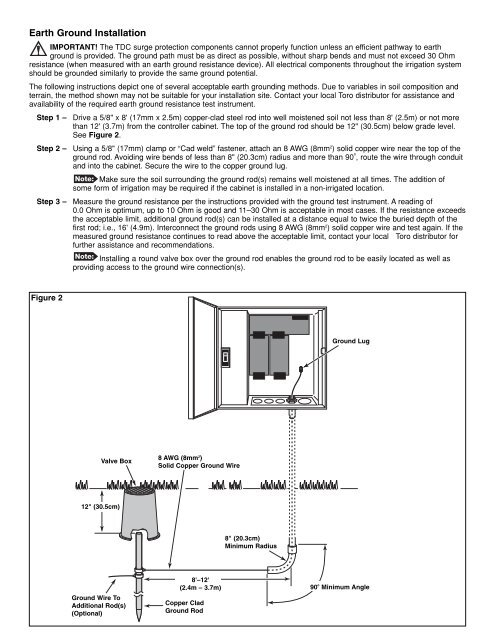
Earth Ground <strong>Installation</strong><br />
IMPORTANT! The <strong>TDC</strong> surge protection components cannot properly function unless an efficient pathway to earth<br />
ground is provided. The ground path must be as direct as possible, without sharp bends and must not exceed 30 Ohm<br />
resistance (when measured with an earth ground resistance device). All electrical components throughout the irrigation system<br />
should be grounded similarly to provide the same ground potential.<br />
The following instructions depict one of several acceptable earth grounding methods. Due to variables in soil composition and<br />
terrain, the method shown may not be suitable for your installation site. Contact your local <strong>Toro</strong> distributor for assistance and<br />
availability of the required earth ground resistance test instrument.<br />
Step 1 –<br />
Step 2 –<br />
Step 3 –<br />
Drive a 5/8" x 8' (17mm x 2.5m) copper-clad steel rod into well moistened soil not less than 8' (2.5m) or not more<br />
than 12' (3.7m) from the controller cabinet. The top of the ground rod should be 12" (30.5cm) below grade level.<br />
See Figure 2.<br />
Using a 5/8" (17mm) clamp or “Cad weld” fastener, attach an 8 AWG (8mm 2 ) solid copper wire near the top of the<br />
ground rod. Avoiding wire bends of less than 8" (20.3cm) radius and more than 90 o , route the wire through conduit<br />
and into the cabinet. Secure the wire to the copper ground lug.<br />
Make sure the soil surrounding the ground rod(s) remains well moistened at all times. The addition of<br />
some form of irrigation may be required if the cabinet is installed in a non-irrigated location.<br />
Measure the ground resistance per the instructions provided with the ground test instrument. A reading of<br />
0.0 Ohm is optimum, up to 10 Ohm is good and 11–30 Ohm is acceptable in most cases. If the resistance exceeds<br />
the acceptable limit, additional ground rod(s) can be installed at a distance equal to twice the buried depth of the<br />
first rod; i.e., 16' (4.9m). Interconnect the ground rods using 8 AWG (8mm 2 ) solid copper wire and test again. If the<br />
measured ground resistance continues to read above the acceptable limit, contact your local <strong>Toro</strong> distributor for<br />
further assistance and recommendations.<br />
Installing a round valve box over the ground rod enables the ground rod to be easily located as well as<br />
providing access to the ground wire connection(s).<br />
Figure 2<br />
Ground Lug<br />
Valve Box<br />
8 AWG (8mm 2 )<br />
Solid Copper Ground Wire<br />
12" (30.5cm)<br />
8" (20.3cm)<br />
Minimum Radius<br />
Ground Wire To<br />
Additional Rod(s)<br />
(Optional)<br />
8'–12'<br />
(2.4m – 3.7m)<br />
Copper Clad<br />
Ground Rod<br />
90 o Minimum Angle