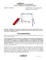
Verona Swing Set Owner's Manual and Assembly ... - Instep.net
Verona Swing Set Owner's Manual and Assembly ... - Instep.net
Verona Swing Set Owner's Manual and Assembly ... - Instep.net

Create successful ePaper yourself
Turn your PDF publications into a flip-book with our unique Google optimized e-Paper software.
<strong>Verona</strong> <strong>Swing</strong> <strong>Set</strong><br />
Owner’s <strong>Manual</strong> <strong>and</strong> <strong>Assembly</strong> Instruction<br />
Model #: 22-PS100<br />
Model Name: <strong>Verona</strong> <strong>Swing</strong> <strong>Set</strong><br />
<strong>Manual</strong> revision: 4/2006<br />
Important: Keep this owner’s manual; do not discard in case you need to contact Pacific Cycle, Inc.<br />
in the future. Should there be a change of ownership, please transfer this manual to the new owner to<br />
ensure proper assembly <strong>and</strong> safety.<br />
90 DAY LIMITED WARRANTY<br />
Pacific Cycle, Inc. warrants this product to be free of defective materials <strong>and</strong> workmanship for 90 days from<br />
the date of original purchase.<br />
THIS LIMITED WARRANTY IS THE ONLY WARRANTY APPLICABLE TO THIS PRODUCT,<br />
AND IS EXPRESSLY IN LIEU OF ANY OTHER WARRANTY. ANY IMPLIED WARRANTIES,<br />
INCLUDING ANY WARRANTY OF MERCHANTABILITY AND WARRANTY OF FITNESS<br />
FOR A PARTICULAR PURPOSE, IS LIMITED IN DURATION TO THE DURATION OF THIS<br />
EXPRESS WARRANTY. This limited warranty gives you specific legal rights <strong>and</strong> you may also have<br />
other rights which may vary from state to state. This warranty is extended only to the original consumer<br />
purchaser for non-commercial use.<br />
PACIFIC CYCLE, INC. IS NOT RESPONSIBLE FOR INCIDENTAL OR CONSEQUENTIAL<br />
DAMAGES. THIS LIMITED WARRANTY DOES NOT COVER ANY PERSONAL INJURIES,<br />
DAMAGE TO, OR FAILURE OF THE PRODUCT OR ANY OTHER LOSSES DUE TO ACCIDENT,<br />
ABUSE, MISUSE, ALTERATION, NEGLECT, NORMAL WEAR AND TEAR, RUST, IMPROPER<br />
ASSEMBLY, IMPROPER FIT, IMPROPER MAINTENANCE OR USE OF UNAUTHORIZED<br />
REPLACEMENT PARTS NOT DESIGNED FOR THE PRODUCT.<br />
1 ©2006 Pacific Cycle, Inc.
To make a claim under warranty, notification of such defect must be given to Pacific Cycle, Inc. By calling<br />
the phone number below, you will be instructed on how the product or part needing replacement should be<br />
shipped postpaid to Pacific Cycle, Inc.<br />
Customer Service <strong>and</strong> Assistance<br />
1-800-242-6110<br />
Monday – Friday 8am-5pm CST<br />
Please contact the Playsafe customer service team if you have any questions about our product, need assembly assistance or<br />
need replacement parts for the swing set. You may also contact us by mail:<br />
Playsafe Customer Service<br />
Pacific Cycle, Inc<br />
4730 East Radio Tower Lane<br />
Olney, IL 62450<br />
Or by email: info@Playsafeoutdoors.com<br />
WARNINGS AND SAFETY INFORMATION<br />
OBSERVE ALL WARNINGS AND STATEMENTS IN ORDER TO REDUCE THE RISK OF INJURY OR DEATH.<br />
• BE SURE TO READ AND FOLLOW ALL OF THE ENCLOSED INSTRUCTIONS BEFORE ASSEMBLY AND USE OF<br />
THIS SWING SET.<br />
• BEFORE YOU ASSEMBLE THE SWING SET, FIND LEVEL GROUND NOT LESS THAN 6 FEET FROM ANY<br />
STRUCTURE OR OBSTRUCTION TO THE SWING SET. YOUR SWING SET MUST HAVE CLEARANCE ON ALL<br />
SIDES.<br />
• TO PREVENT SERIOUS INJURY, DO NOT ALLOW CHILDREN TO PLAY ON THE SWING SET UNTIL IT IS<br />
COMPLETELY INSTALLED.<br />
• DO NOT INSTALL THE SWING SET OVER CONCRETE, PACKED DIRT, OR ANY OTHER HARD SURFACE.<br />
A FALL ONTO A HARD SURFACE CAN RESULT IN SERIOUS INJURY OR DEATH TO THE USER.<br />
• ONLY ADULTS SHOULD ASSEMBLE OR DISASSEMBLE THIS SWING SET.<br />
• THIS PRODUCT MUST BE ANCHORED. ANCHORS ARE SOLD SEPARATELY. CALL 1-800-242-6110 OR<br />
EMAIL INFO@PLAYSAFEOUTDOORS.COM<br />
• NEVER LEAVE CHILDREN UNATTENDED.<br />
• ADULT SUPERVISION OF CHILDREN IS REQUIRED AT ALL TIMES WHEN ON OR AROUND THIS SWING SET.<br />
• DO NOT SWING TOO HIGH OR AT AN ANGLE.<br />
• DO NOT HANG ON OR CLIMB FROM STRUCTURAL MEMBERS OF THE SWING SET.<br />
• DO NOT EXCEED THE INTENDED WEIGHT LIMIT OR MAXIMUM NUMBER OF USERS FOR THE SWING SET.<br />
• THE INTENDED AGE FOR USE OF THIS PRODUCT IS 2 YEARS TO 10 YEARS OLD, UNDER ADULT<br />
SUPERVISION. CHILDREN UNDER 2 YEARS HAVE A HIGHER RISK OF ENTRAPMENT AND INJURY.<br />
• BE SURE TO OBSERVE YOUR CHILDREN AND INSURE THAT THEY HAVE THE STRENGTH AND SKILLS TO<br />
ENJOY ALL THE RIDES SAFELY BEFORE USE ON THEIR OWN.<br />
• DO NOT ALLOW CHILDREN TO WALK CLOSE TO, BEHIND, OR IN FRONT OF MOVING ITEMS.<br />
• DO NOT ALLOW CHILDREN TO TWIST SWING CHAINS OR LOOP THEM OVER THE TOP BAR. THIS MAY<br />
REDUCE THE STRENGTH OF THE CHAIN.<br />
• TEACH AND INSTRUCT CHILDREN NOT TO SWING EMPTY SEATS.<br />
• INSTRUCT CHILDREN HOW TO SIT IN THE CENTER OF THE SEATS AND SWING WITH THEIR FULL WEIGHT<br />
ON THE SEAT.<br />
• WARN CHILDREN NOT TO USE THE EQUIPMENT IN ANY MANNER OTHER THAN INTENDED.<br />
2 ©2006 Pacific Cycle, Inc.
• WARN CHILDREN NOT TO GET OFF THE RIDES WHILE IN MOTION.<br />
• WARN CHILDREN TO DRESS APPROPRIATELY. LOOSE FITTING CLOTHING IS POTENTIALLY HAZARDOUS<br />
WHEN USING THE SWING SET.<br />
• EQUIPMENT MAY BE SLIPPERY WHEN WET.<br />
• DO NOT ALLOW CHILDREN TO USE THE EQUIPMENT WHEN WET.<br />
• PARENTS SHOULD REGULARLY CHECK OPENINGS AND SURFACES, SUCH AS SLIDES, FOR ITEMS THAT<br />
MAY BE HAZARDOUS.<br />
• PARENTS SHOULD CHECK SWING CHAINS TO INSURE THEY ARE SECURE AND CAN NOT BE LOOPED<br />
BACK ON THEMSELVES.<br />
• DO NOT PLACE ANY PART OF THE BODY NEAR MOVING PARTS ON GLIDE RIDES OR TOP BRACKETS.<br />
• NEVER SLIDE HEAD FIRST DOWN THE SLIDE.<br />
• VERIFY THAT ALL SWINGS AND CHAINS ARE SECURED AT BOTH ENDS.<br />
• NEVER ATTACH ANY MATERIALS THAT ARE NOT SPECIFICALLY DESIGNED FOR USE WITH THIS SWING<br />
SET, SUCH AS JUMP ROPES, PET LEASHES, ROPE OR CORDS AND OTHER CHAINS AS THESE POSE A<br />
POTENTIAL STRANGULATION HAZARD.<br />
PROPER USE<br />
This swing set is designed for use by children ages 2 to 10 under adult supervision. Do not leave children unattended. The<br />
maximum number of users this unit is intended for is 5 children with a maximum weight of 105 lbs each. The maximum<br />
fall height for this swing set is 74”.<br />
Single Ride (i.e. <strong>Swing</strong>) 105 lbs<br />
Double Ride (i.e. Glider) 210 lbs<br />
This product is designed for normal residential use only. This product is not designed for use in day care, nurseries, or<br />
other public places. This product is to be assembled by adults only in the manner described within this owner’s manual.<br />
The swing set must be anchored. Anchors are not included in this carton. For more information on anchoring, please see<br />
the section below.<br />
ANCHORING<br />
ANCHORING is necessary to prevent tipping, lifting, <strong>and</strong> overturning. Playsafe recommends anchoring the swing set<br />
in concrete, especially in soft or s<strong>and</strong>y soil. When this is not possible, anchors can be purchased by calling 1-800-242-6110.<br />
To anchor the swing set in concrete, dig a hole at least 5” deep <strong>and</strong> 10” to 12” in diameter. Place the swing set leg in the<br />
hole, preferably on a brick or stone to keep if from sinking. Be sure the swing leg is set 3” below the ground. Also make<br />
sure the swing set is level. Pour concrete around the legs <strong>and</strong> fill the hole. Cover concrete adequately using the<br />
recommended surfacing instruction in this manual. Allow the concrete to cure according to the concrete manufacturer’s<br />
instruction before use.<br />
CONSUMER INFORMATION FOR PLAYGROUND SURFACING MATERIALS<br />
The U.S. Consumer Product Safety Commission estimates that 100,000 playground related injuries are treated annually in U.S.<br />
hospital emergency rooms. Injuries involving this hazard pattern tend to be among the most serious of all playground injuries,<br />
<strong>and</strong> have the potential to be fatal, particularly when the injury is to the head. The surface under <strong>and</strong> around the playground<br />
equipment can be a major factor in determining the injury-causing potential of a fall. It is self-evident that a fall on a shockabsorbing<br />
surface is less likely to cause a serious injury than a fall onto a hard surface. Playground equipment should never be<br />
placed on a hard surface such as concrete or asphalt <strong>and</strong> while grass may appear to be acceptable it may quickly turn to hard,<br />
packed earth in areas of high traffic. Shredded bark mulch, wood chips, fine s<strong>and</strong> or fine gravel are considered to be acceptable<br />
shock absorbing surfaces when installed <strong>and</strong> maintained at a sufficient depth under <strong>and</strong> around playground equipment.<br />
3 ©2006 Pacific Cycle, Inc.
The following table lists the maximum height from which a child would not be expected to sustain a life-threatening injury in a<br />
fall onto four different loose-fill surfacing materials if they are installed <strong>and</strong> maintained at depths of 6, 9, <strong>and</strong> 12 in. However, all<br />
injuries due to a fall can not be prevented no matter what surfacing materials are used.<br />
FALL HEIGHT IN FEET FROM WHICH A LIFE<br />
THREATENING INJULY WOULD NOT BE EXPECTED<br />
Material Type 6 in. depth 9 in. 12 in.<br />
Double Shredded<br />
Bark Mulch 6’ 10’ 11’<br />
Wood Chips 6’ 7’ 12’<br />
Fine S<strong>and</strong> 5’ 5’ 9’<br />
Fine Gravel 6’ 7’ 10’<br />
It is recommended that a shock absorbing material should extend a minimum of 6’ in all directions from the perimeter of the<br />
stationary equipment such as climbers <strong>and</strong> slides. However, because children may deliberately jump from a moving swing, the<br />
shock absorbing material should extend in front <strong>and</strong> rear of the swing a minimum distance of 2 times the height of the pivot point<br />
measured from a point directly beneath the pivot on the supporting structure.<br />
The information is intended to assist in comparing the relative shock-absorbing properties of various materials. No particular<br />
method is recommended over another. However, every material is only effective when properly maintained. Materials should be<br />
checked periodically <strong>and</strong> replenished to maintain correct depth as determined necessary for your equipment. The choice of a<br />
material depends on the type <strong>and</strong> height of the playground equipment, the availability of material in your area <strong>and</strong> its cost.<br />
(The information above has been extracted from CPSC documents “Playground Surfacing – technical Information guide” <strong>and</strong><br />
“H<strong>and</strong>book for public Playground Safety.” Copies of these documents can be obtained by sending a postcard to the: Office of<br />
Public Affairs, USCPSC, Washington D.C., 20207 or by calling 1-800-638-2772.<br />
CARE AND MAINTENANCE<br />
• Check all nuts <strong>and</strong> bolts twice monthly during the usage season for tightness <strong>and</strong> tighten as required. It is particularly<br />
important that all nuts <strong>and</strong> bolts are checked prior to the first use each season.<br />
• For extended use, remove plastic swing seats <strong>and</strong> take indoors when the temperature drops below 32º F.<br />
• Oil all metallic moving parts monthly during the usage season.<br />
• Check all coverings for bolts <strong>and</strong> sharp edges weekly during usage season to be certain they are in place. Replace as<br />
needed. It is particularly important that all coverings are checked prior to the first use each season.<br />
• S<strong>and</strong> any rusted areas of the tubing <strong>and</strong> repaint with a non-lead based paint meeting the requirements of Title 16 CFR<br />
Part 1303.<br />
LOCATION AND PLACEMENT OF YOUR SWING SET<br />
• Place your swing set a MINIMUM of six (6) feet from any other hard or fixed object.<br />
• Do not place your swing set underneath electrical lines. If you must, ensure that there is a minimum overhead<br />
clearance of six (6) feet.<br />
• Please note the CPSC surfacing materials recommendations on page 3.<br />
TOOLS REQUIRED FOR ASSEMBLY<br />
Your swing set comes with two 5mm Allen wrenches for the assembly of most of this product. You may also need to have the<br />
following tools available:<br />
• Adjustable wrench<br />
• Phillips screwdriver<br />
• Needle-nose pliers<br />
4 ©2006 Pacific Cycle, Inc.
Although we take pride in the quality of our swing sets, on occasion there may be a burr or rough part which will require a metal<br />
file to remove before use.<br />
PARTS LIST FOR SWING SET<br />
Remove all parts from the package <strong>and</strong> lay them out before you begin assembly. If any parts are missing, please call 1-<br />
800-242-6110.<br />
Main Frame<br />
Name<br />
Each<br />
Top Bar with Corner Fittings <strong>and</strong><br />
<strong>Swing</strong> Hooks 1<br />
Leg 4<br />
Support Bar 2<br />
Glider<br />
Name<br />
Each<br />
Glider Pole (vertical) with Foot Rests 2<br />
Glider Pole (horizontal) with Seats 2<br />
Glider Frame Attachment 1<br />
<strong>Swing</strong>s<br />
Name<br />
Each<br />
<strong>Swing</strong> Seat with Chains 2<br />
Slide<br />
Name<br />
Each<br />
Rail/Ladder Leg 2<br />
Front Leg 1<br />
Slide 1<br />
Ladder Step<br />
PRE-ASSEMBLED HARDWARE<br />
For easier assembly, Playsafe has pre-assembled some of the parts for you. Most of the screws <strong>and</strong> bolts should already be<br />
in place. If removal of this hardware is required for certain assembly steps, it should be replaced in its original position.<br />
Hardware shown in the assembly steps is actual size.<br />
MAIN FRAME ASSEMBLY<br />
Required Parts:<br />
Top Bar x1<br />
Corner Fitting x2 (attached to the top bar)<br />
Leg x4<br />
Support Bar x2<br />
5 ©2006 Pacific Cycle, Inc.
Pre-Assembled Parts:<br />
• Corner fittings should be attached to the top bar.<br />
• <strong>Swing</strong> hooks should be in place on the top bar.<br />
• Hardware for the legs should be in place in the corner fitting prongs.<br />
• Hardware for the support bars should be in place on the legs.<br />
Step Illustration Instructions Hardware Reference<br />
1 Remove the hardware from the prong of a<br />
corner fitting in order to insert one of the<br />
legs.<br />
Part Ref. #: PSHW10<br />
2 Align the two sets of holes <strong>and</strong> replace the<br />
hardware through the corner fitting prong<br />
<strong>and</strong> leg to secure the leg. Do not over<br />
tighten the screws. After all parts are<br />
assembled you will need to tighten again.<br />
Part Ref. #: PSHW10<br />
3 Repeat the process for the three remaining<br />
legs.<br />
Part Ref. #: PSHW10<br />
4 The swing set frame is now ready to st<strong>and</strong>.<br />
5 Remove the hardware from the middle<br />
section of a leg. Match up the holes of the<br />
mid-leg <strong>and</strong> support bar <strong>and</strong> re-insert the<br />
hardware through both. Repeat the process<br />
for the opposite side. It may be necessary<br />
to pull both legs towards each other in order<br />
for the holes to align properly.<br />
NOTE: One support bar has holes for the<br />
slide attachment. The holes should be<br />
positioned toward the front of the swing set.<br />
Part Ref. #: PSHW12<br />
6 ©2006 Pacific Cycle, Inc.
GLIDER ASSEMBLY<br />
Required Parts:<br />
Vertical Poles x2 (Footrests attached)<br />
Glider attachment x1<br />
Horizontal Poles x2 (Seats attached)<br />
Pre-Assembled Parts:<br />
• The seats should be attached to the horizontal poles. These must be disassembled to complete the steps below.<br />
• The foot rests should be attached to the vertical poles.<br />
Step Illustration Instructions Hardware Reference<br />
1 Secure the glider attachment with the V-<br />
screw <strong>and</strong> the bolts at the squared portion<br />
of the top bar.<br />
Part Ref. #: PSHW35, PSHW22<br />
2 Attach the two vertical poles to the glider<br />
attachment. Start by removing the<br />
hardware from the lower section of the<br />
glider attachment. Align the vertical bar<br />
with the glider attachment <strong>and</strong> re-insert the<br />
hardware. Repeat the process for the other<br />
side.<br />
NOTE: The curved portion of the pole is<br />
the top <strong>and</strong> it should face the inside of the<br />
swing frame.<br />
Part Ref. #: PSHW21, PSHW36<br />
7 ©2006 Pacific Cycle, Inc.
3 Connect the two horizontal poles (must<br />
first be disassembled from the seats) to the<br />
two vertical poles using the hardware<br />
provided. Be sure that the plastic bushings<br />
are between the vertical poles <strong>and</strong><br />
horizontal poles.<br />
Part Ref. #: PSHW15, PSHW11<br />
4 Reattach the seats onto the horizontal poles<br />
using the flat headed screw, washer, <strong>and</strong><br />
lock nut.<br />
Part Ref. #: PSHW1<br />
5 Once fully assembled, check that the glider<br />
swings freely. If it does not, make sure<br />
that the bolts holding the vertical poles to<br />
the top bar attachment are not overly<br />
tightened.<br />
Part Ref. #: PSHW21, PSHW36<br />
SWING ASSEMBLY<br />
Pre-Assembled Parts<br />
• <strong>Swing</strong> seats should be attached to the chain.<br />
Step Illustration Instructions Hardware Reference<br />
1 Hang the swings in place from the swing hooks.<br />
2 Check the lock nut <strong>and</strong> bolt on the swing seat to<br />
make sure that they are secure.<br />
Part Ref. #: PSSH11, PSHW13<br />
8 ©2006 Pacific Cycle, Inc.
SLIDE ASSEMBLY<br />
Required Parts:<br />
Slide x1 Rail/Ladder Leg x2 Front Leg x1 Ladder Step x2 Link Bar x2<br />
Proper Placement:<br />
Slide <strong>Assembly</strong> Correct Location Incorrect Location<br />
Pre-Assembled Parts:<br />
• The screws <strong>and</strong> bolts for the slide rail/ladder legs are inserted on the slide. They will need to be removed prior to<br />
inserting the legs into the slide.<br />
• The ladder steps should have screws <strong>and</strong> nuts installed. These will need to be removed prior to inserting the legs <strong>and</strong><br />
then reassembled with the head of the screw facing out.<br />
Step Illustration Instructions Hardware Reference<br />
1 Remove the screws, washers, <strong>and</strong> lock nuts from Part Ref. #: PSHW24<br />
the holes in the slide.<br />
2 Insert the rail/ladder legs through the holes in the<br />
top of the slide. Align the ladder holes with the<br />
slide holes.<br />
3 Insert the screws through the holes in the back of<br />
the slide <strong>and</strong> secure the slide to the h<strong>and</strong> rails with<br />
the lock nut.<br />
Part Ref. #: PSHW24<br />
9 ©2006 Pacific Cycle, Inc.
4 Locate the slide front leg <strong>and</strong> insert it into the front<br />
outside h<strong>and</strong> rail tube on the underside of the slide.<br />
Place a screw in that hole <strong>and</strong> secure it with the<br />
lock nut.<br />
NOTE: For stability, this leg should be placed on<br />
the outside of the slide, opposite the swing set<br />
frame.<br />
5 Insert the screw into the remaining hole on the<br />
slide <strong>and</strong> secure the h<strong>and</strong> rail to the slide with the<br />
lock nut.<br />
Part Ref. #: PSHW24<br />
Part Ref. #: PSHW24<br />
6 Slide the two ladder steps onto the legs of the slide.<br />
Align the holes <strong>and</strong> secure the steps with the<br />
screws <strong>and</strong> locking nuts. The screw head should<br />
be facing the outside.<br />
NOTE: Once assembled <strong>and</strong> the slide is st<strong>and</strong>ing<br />
upright, the steps should be flat <strong>and</strong> parallel with<br />
the ground. If they are at an angle, they will need<br />
to be removed, turned around, <strong>and</strong> reassembled.<br />
7 To attach the slide to the frame, locate the two link<br />
bars, remove the hardware, <strong>and</strong> re-attach to the side<br />
support bar with the holes.<br />
Part Ref. #: PSHW5<br />
Part Ref. # PSHW17<br />
TIP: In order to keep the slide legs from sinking into the ground, place a flat rock or a brick under the legs. You should dig<br />
out a place for the brick so the slide remains even.<br />
IMPORTANT LAST STEPS!<br />
TIGHTEN ALL HARDWARE. Do not allow children to play on the swing set until it is fully assembled, all items are<br />
tightened, <strong>and</strong> the unit is properly anchored.<br />
• Do not over tighten nuts <strong>and</strong> bolts. Once they are tight, turn them ½ rotation more to be sure they are secure.<br />
• Check all parts on all rides before allowing a child on the swing set.<br />
• Be sure to check <strong>and</strong> tighten the hardware on a regular basis to ensure the safety of the users.<br />
Your Playsafe <strong>Verona</strong> <strong>Swing</strong> <strong>Set</strong> should now be fully assembled!<br />
10 ©2006 Pacific Cycle, Inc.