
You also want an ePaper? Increase the reach of your titles
YUMPU automatically turns print PDFs into web optimized ePapers that Google loves.
GAMMA instabus<br />
Application Descriptions<br />
November 2010<br />
07 B0 KNX / DALI Gateway 981C0C<br />
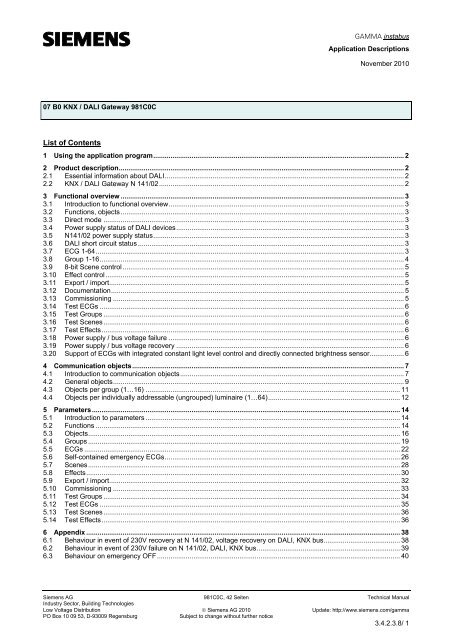
<strong>List</strong> <strong>of</strong> <strong>Contents</strong><br />
1 Using the application program................................................................................................................................... 2<br />
2 Product description..................................................................................................................................................... 2<br />
2.1 Essential information about DALI............................................................................................................................. 2<br />
2.2 KNX / DALI Gateway N 141/02................................................................................................................................ 2<br />
3 Functional overview .................................................................................................................................................... 3<br />
3.1 Introduction to functional overview........................................................................................................................... 3<br />
3.2 Functions, objects.................................................................................................................................................... 3<br />
3.3 Direct mode ............................................................................................................................................................. 3<br />
3.4 Power supply status <strong>of</strong> DALI devices....................................................................................................................... 3<br />
3.5 N141/02 power supply status................................................................................................................................... 3<br />
3.6 DALI short circuit status ........................................................................................................................................... 3<br />
3.7 ECG 1-64................................................................................................................................................................. 3<br />
3.8 Group 1-16............................................................................................................................................................... 4<br />
3.9 8-bit Scene control ................................................................................................................................................... 5<br />
3.10 Effect control............................................................................................................................................................ 5<br />
3.11 Export / import.......................................................................................................................................................... 5<br />
3.12 Documentation......................................................................................................................................................... 5<br />
3.13 Commissioning ........................................................................................................................................................ 5<br />
3.14 Test ECGs ............................................................................................................................................................... 6<br />
3.15 Test Groups ............................................................................................................................................................. 6<br />
3.16 Test Scenes............................................................................................................................................................. 6<br />
3.17 Test Effects.............................................................................................................................................................. 6<br />
3.18 Power supply / bus voltage failure ........................................................................................................................... 6<br />
3.19 Power supply / bus voltage recovery ....................................................................................................................... 6<br />
3.20 Support <strong>of</strong> ECGs with integrated constant light level control and directly connected brightness sensor.................. 6<br />
4 Communication objects.............................................................................................................................................. 7<br />
4.1 Introduction to communication objects..................................................................................................................... 7<br />
4.2 General objects........................................................................................................................................................ 9<br />
4.3 Objects per group (1…16) ..................................................................................................................................... 11<br />
4.4 Objects per individually addressable (ungrouped) luminaire (1…64)..................................................................... 12<br />
5 Parameters................................................................................................................................................................. 14<br />
5.1 Introduction to parameters ..................................................................................................................................... 14<br />
5.2 Functions ............................................................................................................................................................... 14<br />
5.3 Objects................................................................................................................................................................... 16<br />
5.4 Groups ................................................................................................................................................................... 19<br />
5.5 ECGs ..................................................................................................................................................................... 22<br />
5.6 Self-contained emergency ECGs........................................................................................................................... 26<br />
5.7 Scenes................................................................................................................................................................... 28<br />
5.8 Effects.................................................................................................................................................................... 30<br />
5.9 Export / import........................................................................................................................................................ 32<br />
5.10 Commissioning ...................................................................................................................................................... 33<br />
5.11 Test Groups ........................................................................................................................................................... 34<br />
5.12 Test ECGs ............................................................................................................................................................. 35<br />
5.13 Test Scenes........................................................................................................................................................... 36<br />
5.14 Test Effects............................................................................................................................................................ 36<br />
6 Appendix .................................................................................................................................................................... 38<br />
6.1 Behaviour in event <strong>of</strong> 230V recovery at N 141/02, voltage recovery on DALI, KNX bus........................................ 38<br />
6.2 Behaviour in event <strong>of</strong> 230V failure on N 141/02, DALI, KNX bus........................................................................... 39<br />
6.3 Behaviour on emergency OFF............................................................................................................................... 40<br />
Siemens AG 981C0C, 42 Seiten Technical Manual<br />
Industry Sector, Building Technologies<br />
Low Voltage Distribution © Siemens AG 2010 Update: http://www.siemens.com/gamma<br />
PO Box 10 09 53, D-93009 Regensburg<br />
Subject to change without further notice<br />
3.4.2.3.8/ 1
GAMMA instabus<br />
Application Descriptions<br />
November 2010<br />
07 B0 KNX / DALI Gateway 981C0C<br />
1 Using the application program<br />
Product family:<br />
Product type:<br />
Manufacturer:<br />
Lighting<br />
Interface<br />
Siemens<br />
Name: KNX / DALI Gateway N 141/02<br />
Order no.: 5WG1 141-1AB02<br />
2 Product description<br />
2.1 Essential information about DALI<br />
DALI (Digital Addressable Lighting Interface) is a bidirectional<br />
communications interface in accordance with<br />
IEC 60929, whose specification has been defined by<br />
manufacturers <strong>of</strong> electronic ballasts. It not only enables<br />
the receipt <strong>of</strong> e.g. switching and dimming commands<br />
but also the sending <strong>of</strong> status information such as the<br />
failure <strong>of</strong> a lamp or the report <strong>of</strong> a detected error in the<br />
electronic ballast. According to IEC 60929 up to 64<br />
DALI devices can be connected to a DALI line and can<br />
each be assigned an individual device address.<br />
2.2 KNX / DALI Gateway N 141/02<br />
The KNX / DALI gateway N 141/02 is a 4 MU wide,<br />
DIN-rail mounted KNX device with one DALI interface<br />
to which up to 64 DALI actuators (e.g. DALI ballasts)<br />
can be connected to. It is not allowed to connect DALI<br />
sensors to the DALI interface <strong>of</strong> the N 141/02.<br />
The KNX / DALI Gateway N 141/02 enables communicating<br />
with up to 64 DALI devices including detection<br />
and transmission <strong>of</strong> DALI status and failure information<br />
via KNX. DALI actuators can be switched and dimmed<br />
either individually or in groups. If a DALI actuator is assigned<br />
to one <strong>of</strong> the 16 groups it cannot be controlled<br />
individually anymore. An individual name, a group, parameters<br />
and scenes (refer to the application program<br />
description) are assigned to the individual DALI electronic<br />
ballasts during commissioning with the ETS (Engineering<br />
Tool S<strong>of</strong>tware).<br />
Self-test <strong>of</strong> the inverters <strong>of</strong> self-contained emergency<br />
luminaires can be started and the test result reported<br />
via the bus. The type <strong>of</strong> test (function test, short duration<br />
test or long duration test) that has to be started or<br />
has started can be commanded or queried by the new<br />
8-bit object “Start test”. A test result will be reported<br />
automatically at the end <strong>of</strong> a test or can be queried via<br />
the new 3-byte object “Test result”.<br />
Via the object “Emergency operation” all luminaires<br />
controlled by a N 141/02 can be dimmed to the set<br />
“Dimming value on emergency” even when they are not<br />
effected by any mains or DALI power failure. By this all<br />
luminaires may be dimmed to the same brightness level<br />
as all self-contained emergency luminaires.<br />
During “Emergency Operation” all luminaires will not respond<br />
to any on/<strong>of</strong>f or dim commands and cannot be<br />
commissioned.<br />
Note: If individual communication with each individual<br />
DALI device is not required and you wish for example to<br />
simply connect a group <strong>of</strong> dimmable fluorescent lamps<br />
in parallel and control them in the same way as you<br />
would previously have connected and controlled dimmable<br />
electronic control gear (ECG) with a 1...10 V interface,<br />
this is also possible with the switching/dim-ming<br />
actuator N 525E. Status and error signals are also detected<br />
by the N 525E and transmitted, whereby these<br />
signals are as-signed to the respective group and not to<br />
an individual DALI device.<br />
The KNX / DALI Gateway N 141/02 can be used to control<br />
DALI actuators in emergency luminaires. Selfcontained<br />
emergency luminaires containing two DALI<br />
devices (ballast and an inverter, each with a DALI interface)<br />
only up to 32 self-contained emergency luminaires<br />
may be connected to a N 141/02. The gateway<br />
automatically detects if a self-contained emergency luminaire<br />
contains two or only one DALI actuators. Selfcontained<br />
emergency luminaires with two DALI interfaces<br />
and “normal” luminaires with only one DALI interface<br />
may be connected to the N 141/02, but the total<br />
number <strong>of</strong> 64 DALI devices may not be exceeded.<br />
Siemens AG 981C0C, 42 Seiten Technical Manual<br />
Industry Sector, Building Technologies<br />
Low Voltage Distribution © Siemens AG 2010 Update: http://www.siemens.com/gamma<br />
PO Box 10 09 53, D-93009 Regensburg<br />
Subject to change without further notice<br />
3.4.2.3.8/ 2
GAMMA instabus<br />
Application Descriptions<br />
November 2010<br />
07 B0 KNX / DALI Gateway 981C0C<br />
3 Functional overview<br />
3.1 Introduction to functional overview<br />
The application program can only be loaded with the<br />
ETS3.<br />
Type and number <strong>of</strong> communication objects are defined<br />
by the number <strong>of</strong> attached DALI devices, the configured<br />
groups as well as by the functions and objects activated<br />
via the “Functions” and “Objects” parameter windows.<br />
3.2 Functions, objects<br />
The basic functionality <strong>of</strong> the gateway can be expanded<br />
by additional functions and communication objects via<br />
the “Functions” and “Objects” parameter windows. This<br />
includes time-limited switching on <strong>of</strong> lighting during the<br />
night (time-limited cleaning light in night operation), 8-<br />
bit scene control integrated into the gateway, an additional<br />
control <strong>of</strong> light effects and the determination<br />
whether and how the various status objects are to be<br />
transmitted.<br />
3.3 Direct mode<br />
The power supply unit integrated in the N 141/02 supplies<br />
the gateway electronics and generates the DALI<br />
voltage. Additionally, it enables the operation <strong>of</strong> the<br />
gateway and a direct switching <strong>of</strong> all lamps controlled<br />
over its DALI interface even if the N 141/02 has not yet<br />
been commissioned with the ETS or if the communication<br />
via the KNX bus has been interrupted. For this purpose,<br />
the N 141/02 has a pushbutton located bottom<br />
left on its front plate for switching-on the “Direct mode”<br />
as well as for switching back to the “Bus mode”. When<br />
this pushbutton has been pressed for the first time the<br />
yellow light emitting diode (LED) lights up permanently<br />
to indicate direct mode. Then all lamps controlled via<br />
DALI can be switched On or Off all together via the<br />
relevant two pushbuttons on the front plate <strong>of</strong> the gateway:<br />
pressing briefly the upper pushbutton switches the<br />
channel On while pressing briefly the lower push button<br />
switches the channel Off. A red LED integrated in the<br />
upper push button is used to indicate the On state <strong>of</strong><br />
the lamps by a continuous light and to indicate a DALI<br />
cable error by flashing.<br />
Detected faults are displayed using this blink code:<br />
1x blinking Connecting AC 230V to DALI wire is not<br />
permitted<br />
2x blinking DALI short circuit<br />
3x blinking DALI voltage too low!<br />
4x blinking no load / no DALI devices found<br />
If the direct mode button is pressed for a second time,<br />
the yellow LED to indicate direct mode is extinguished<br />
and the N 141/02 is switched to “Bus mode”.<br />
Time functions that have already been launched are interrupted<br />
by switching on the direct mode.<br />
3.4 Power supply status <strong>of</strong> DALI devices<br />
If it is detected (by scanning <strong>of</strong> the connected DALI devices)<br />
that their power supply is missing, this is transmitted<br />
via the object “Mains failure at DALI devices” (0=<br />
no mains failure; 1 = mains failure at DALI devices).<br />
It can be configured using the parameter “Send mains<br />
failure at DALI devices if number <strong>of</strong> DALI devices with<br />
mains failure >=” in the “Functions” window when this<br />
object is to be sent in the event <strong>of</strong> a detected error.<br />
3.5 N141/02 power supply status<br />
The status <strong>of</strong> the common power supply for the DALI<br />
gateway N141/02 and the DALI cable is reported via<br />
the 1-bit “N141/02 power supply failure” status object. If<br />
the object value = “0”, power is supplied. If the object<br />
value = “1”, the power supply to the N141/02 and to<br />
DALI have failed. The gateway is then no longer able<br />
to function, and all DALI ECGs revert to the dimming<br />
status parameter setting in the event <strong>of</strong> DALI bus voltage<br />
failure.<br />
Short-term buffering <strong>of</strong> the power supply for the gateway<br />
electronics ensures that a power supply failure is<br />
recognized and the telegram on the N141/02 power<br />
supply status can still be transmitted.<br />
3.6 DALI short circuit status<br />
A short circuit in the DALI cable is reported via the 1-bit<br />
status object “DALI short circuit”. If the object value =<br />
“0”, there is no short circuit. If the object value = “1”,<br />
the DALI power supply has short-circuited. The gateway<br />
is then no longer able to control the DALI devices,<br />
and all DALI ECGs revert to the dimming status parameter<br />
setting in the event <strong>of</strong> DALI bus voltage failure.<br />
3.7 ECG 1-64<br />
An ECG can either be controlled individually or via a<br />
group. It is not possible to do both at the same time.<br />
Only the objects for ECG are relevant when individually<br />
controlling the individual ECG. (Objects 140 to 631; see<br />
also section 4.)<br />
3.7.1. Switching on / <strong>of</strong>f<br />
Up to 64 DALI ECGs can be switched individually. The<br />
desired switching state can be reached via dimming using<br />
a configurable dimming time.<br />
3.7.2. Dimming brighter / darker<br />
Up to 64 DALI ECGs may be individually dimmed. The<br />
parameter “Dimming time” can be configured.<br />
After receiving the dimming start command the gateway<br />
N 141/02 communicates with the ECGs to dim them<br />
with the configured dimming time to the desired value. If<br />
a stop command is received before completion <strong>of</strong> the<br />
dimming process, the dimming process is aborted and<br />
the dimming value reached is maintained. In timer<br />
mode unless on <strong>of</strong>f command was received the follow-<br />
Siemens AG 981C0C, 42 Seiten Technical Manual<br />
Industry Sector, Building Technologies<br />
Low Voltage Distribution © Siemens AG 2010 Update: http://www.siemens.com/gamma<br />
PO Box 10 09 53, D-93009 Regensburg<br />
Subject to change without further notice<br />
3.4.2.3.8/3
GAMMA instabus<br />
Application Descriptions<br />
November 2010<br />
07 B0 KNX / DALI Gateway 981C0C<br />
up time is started. Switching on / <strong>of</strong>f via dimming can be<br />
configured via a parameter.<br />
3.7.3. Sending 8-bit dimming value<br />
Up to 64 DALI ECGs can be individually dimmed to a<br />
transmitted 8-bit value. The desired dimming value can<br />
be reached using a configurable dimming time.<br />
3.7.4. Dimming value limitations<br />
If an ECG is assigned to a group, it “inherits” the<br />
“Switch-on value”, “Minimum dimming value” and<br />
“Maximum dimming value” perimeters from this group.<br />
If the “Switch-on value” parameter is set to “last value”<br />
for one group, the “minimum dimming value” set for this<br />
group is used as the switch-on value upon receipt <strong>of</strong> an<br />
ON telegram sent to an ECG that has been assigned to<br />
this group.<br />
3.7.5. Switching status<br />
The switching status (On / Off) <strong>of</strong> an individual DALI<br />
ECG can be both reported and queried via the 8-bit<br />
“Status switching, luminaire xy” status object. In this<br />
process bit 0 to bit 5 contain the number <strong>of</strong> the DALI<br />
ECG. Via bit 6 = 1 it is reported that the ECG / the lamp<br />
is switched on. Bit 7 is reserved for future applications.<br />
A change in the switching status will be automatically<br />
transmitted via this object only once it has been triggered<br />
via a switching command or, respectively, via<br />
turning On/Off by dimming brighter/darker or, respectively,<br />
via an 8-bit dimming telegram and if automatic<br />
sending is enabled. No telegrams are dispatched via<br />
this status object in the event <strong>of</strong> switching status<br />
changes in the group.<br />
If a send request is sent to this object, this request must<br />
contain the number <strong>of</strong> the DALI ECG in bit 0 to 5 and bit<br />
6 and 7 must be set to “1”. The switching status will always<br />
be transmitted upon a send request, irrespective<br />
<strong>of</strong> where it came from.<br />
3.7.6. Dimming value status<br />
The dimming status (0...100%) <strong>of</strong> an individual DALI<br />
ECG can be both reported and queried via the 16-bit<br />
“Status dimming value, luminaire xy” status object. In<br />
this process bit 8 to bit 13 contain the number <strong>of</strong> the<br />
DALI ECG. Via bit 14 = 1 it is displayed that the ECG /<br />
the lamp is switched on. Bit 15 is reserved for future<br />
applications. Bit 0 to bit 7 contain the current dimming<br />
status as an 8-bit value (0...100%).<br />
A change in the dimming status will be automatically<br />
transmitted via this object only once it has been triggered<br />
via a switching command or, respectively, via a<br />
dimming value telegram and the automatic sending is<br />
released. No telegrams are dispatched via this status<br />
object in the event <strong>of</strong> brightness changes in the group.<br />
If a send request is sent to this object, this request must<br />
contain the number <strong>of</strong> the DALI ECG in bit 8 to 13 and<br />
bit 14 and 15 must be set to “1”. The dimming status<br />
will always be transmitted upon a send request, irrespective<br />
<strong>of</strong> where it came from.<br />
3.7.7. Failure status<br />
The failure status <strong>of</strong> an individual DALI ECG can be<br />
both reported and queried via the 8-bit “Failure status,<br />
luminaire xy” status object. In this process bit 0 to bit 5<br />
contain the number <strong>of</strong> the DALI ECG. A lamp error is<br />
reported via bit 6 = 1 and an ECG error via bit 7 = 1.<br />
If a send request is sent to this object, this request must<br />
contain the number <strong>of</strong> the DALI ECG in bit 0 to 5 and bit<br />
6 and 7 must be set to “1”.<br />
3.7.8. CIN device identification<br />
DALI devices from the company OSRAM include a<br />
clear 16-figure identification number, the CIN device<br />
identification (CIN = Chip Identification Number). Light<br />
manufacturers can then select the CIN code and attach<br />
a sticker with the CIN code to their lights with integrated<br />
DALI ECG. One CIN can be assigned to each DALI<br />
ECG attached to the N 141/02, via which the ECG can<br />
be directly addressed during commissioning. In order to<br />
facilitate entry, the 16-digit CIN should be entered as<br />
eight 2-digit numbers.<br />
3.8 Group 1-16<br />
Only the objects for groups are relevant when controlling<br />
ECGs via groups. (Objects 12 to 139; see also section<br />
4.)<br />
An ECG can either be controlled individually or via a<br />
group. It is not possible to do both at the same time.<br />
3.8.1. Switching on / <strong>of</strong>f<br />
The DALI devices attached to the gateway can be assigned<br />
to up to 16 groups.<br />
When a switch-on telegram is sent to a group the parameter<br />
setting determines whether the configured<br />
dimming value or the value prior to switching <strong>of</strong>f will be<br />
set. If the switch-on value is below the configured minimum<br />
value, the minimum value is set; if the value is<br />
above the maximum value, the maximum value is set.<br />
Parameters can be used to set whether the desired<br />
value is jumped or gradually dimmed to. Switch-<strong>of</strong>f<br />
telegrams always switch <strong>of</strong>f. Depending on parameter<br />
setting, switch-on telegrams activate follow-up times.<br />
3.8.2. Dimming brighter/darker<br />
The “dimming time” feature is adjustable. After the start<br />
command is received gateway N 141/02 commences<br />
communication with the ECGs in order to change the<br />
dimming value in the indicated direction using the configured<br />
dimming time. If a stop command is received<br />
before the dimming process is completed, the dimming<br />
process is cancelled and the dimming value obtained is<br />
maintained. In time-switch operation, the follow-up time<br />
Siemens AG 981C0C, 42 Seiten Technical Manual<br />
Industry Sector, Building Technologies<br />
Low Voltage Distribution © Siemens AG 2010 Update: http://www.siemens.com/gamma<br />
PO Box 10 09 53, D-93009 Regensburg<br />
Subject to change without further notice<br />
3.4.2.3.8/4
GAMMA instabus<br />
Application Descriptions<br />
November 2010<br />
07 B0 KNX / DALI Gateway 981C0C<br />
is (re) commenced if the device has not been switched<br />
<strong>of</strong>f. Parameters can be used to set whether dimming<br />
can be used to switch on and <strong>of</strong>f.<br />
3.8.3. Sending 8-bit dimming value<br />
The communication object with the description “Dimming<br />
value, group X” sets all ECGs <strong>of</strong> this group to the<br />
transmitted dimming value. Parameters can be set to<br />
determine whether this value comes on immediately or<br />
is brightened gradually. If this object contains the value<br />
0, the corresponding group is switched <strong>of</strong>f. Values<br />
smaller than the minimum value (with the exception <strong>of</strong><br />
the value 0) and values bigger than the maximum value<br />
are limited to the minimum / maximum dimming value.<br />
A parameter can be used to determine whether a<br />
switched-<strong>of</strong>f ECG takes over the received value immediately<br />
and switches on or only takes over the received<br />
value when there is an ON command. The configured<br />
switch-on value is then invalid. Depending on parameter<br />
setting, the dimming value telegrams also activate<br />
the follow-up times.<br />
3.8.4. Dimming value limitations<br />
A maximum and minimum dimming value can be configured<br />
via the limitation. For all switching and dimming<br />
procedures the dimming value can only be changed<br />
within the configured limits.<br />
Note:<br />
Status annunciations may be delayed by up to six (6)<br />
seconds after a switching or dimming command has<br />
been completed.<br />
3.8.5. Switching status<br />
The on/<strong>of</strong>f status <strong>of</strong> each group can be sent via a<br />
“Status switching, group x” object upon a read request<br />
or automatically when the object value is changed.<br />
3.8.6. Dimming value status<br />
The “Status dimming value, group x” object is an 8-bit<br />
status object. It contains the current dimming value <strong>of</strong><br />
the respective group. It can be sent and / or read independently.<br />
3.8.7. Lamp error status<br />
One recognized lamp failure in a participant in this<br />
group can be reported per group via the 1-bit "Status<br />
lamps, group x” object or, respectively, the status can<br />
be queried at any time.<br />
3.8.8. ECG error status<br />
One recognized ECG failure in a participant in this<br />
group can be reported per group via the 1-bit "Status<br />
ECGs, Group x” object or, respectively, the status can<br />
be queried at any time.<br />
3.8.9 Failure status<br />
The failure status <strong>of</strong> a group can be reported or read via<br />
the 8-bit status object „Failure status, Group x“.<br />
The error code contains information about the number<br />
<strong>of</strong> defective ECGs / converters and lamps. Additionally<br />
it shows if lamps and/or ECGs for emergency lighting<br />
have failed.<br />
3.9 8-bit Scene control<br />
The application program makes it possible to parameterize<br />
up to 16 scenes, each <strong>of</strong> which can contain up<br />
to 16 groups and/or up to 64 ECG’s. The saving and retrieving<br />
<strong>of</strong> scenes is effected via the 8-bit communication<br />
object “8-bit scene, retrieve / save”.<br />
Time functions cannot be executed within a scene.<br />
3.10 Effect control<br />
The application program contains a special effects control<br />
that can be used to produce running light effects or<br />
cyclically repeating coloured light effects. Recalling and<br />
stopping <strong>of</strong> a special effect is effected via the 8-bit<br />
communication object “Effect, recall / stop”.<br />
3.11 Export / import<br />
The export mechanism makes it possible to save the<br />
parameter setting <strong>of</strong> a KNX / DALI Gateway N 141/02 in<br />
a file. The numbers and names <strong>of</strong> the DALI ECGs assigned<br />
upon commissioning are also exported to this<br />
file. These exported numbers, names and group allocations<br />
are only valid, however, for as long as no new initialization<br />
<strong>of</strong> ECGs is carried out on the associated<br />
KNX / DALI Gateway N 141/02 or, respectively, no<br />
other application has been loaded into the device. The<br />
export file can be used, for example, to import the parameter<br />
settings into another project data base or into a<br />
newer version <strong>of</strong> the application program.<br />
The import function only imports data from the application<br />
program 07 B0 KNX / DALI Gateway 981Cxx. Conversion<br />
<strong>of</strong> the data <strong>of</strong> other application programs in order<br />
then to be able to load them into the N 141/02 are<br />
not part <strong>of</strong> the functional scope <strong>of</strong> the import function.<br />
3.12 Documentation<br />
The application program makes it possible to print out<br />
the entire parameter setting <strong>of</strong> the N 141/02.<br />
3.13 Commissioning<br />
Note:<br />
The application program can only be imported by ETS 3<br />
starting with version 3.0 f.<br />
Siemens AG 981C0C, 42 Seiten Technical Manual<br />
Industry Sector, Building Technologies<br />
Low Voltage Distribution © Siemens AG 2010 Update: http://www.siemens.com/gamma<br />
PO Box 10 09 53, D-93009 Regensburg<br />
Subject to change without further notice<br />
3.4.2.3.8/5
GAMMA instabus<br />
Application Descriptions<br />
November 2010<br />
07 B0 KNX / DALI Gateway 981C0C<br />
Following download by means <strong>of</strong> ETS 3, all DALI ECGs<br />
that are attached to the Gateway N 141/02 can be established<br />
and displayed. An individual name <strong>of</strong> up to 50<br />
characters long can then be assigned to every ECG<br />
and the EBS can be allocated to the individual groups<br />
and tested.<br />
The individual name assigned in each case to an ECG<br />
and a group is automatically adopted as the object<br />
name in the ECG and group objects. By printing out the<br />
documentation it can be followed which ECG has which<br />
number and name / which group has which name and<br />
which ECGs are allocated to it.<br />
Note:<br />
If during a download an ECG cannot be contacted either<br />
because it is missing or the installation is faulty this<br />
ECG is not downloaded to. ECGs that could not be<br />
downloaded to are annuniciated with an ECG error.<br />
This also applies to dummy ECGs.<br />
The commissioning function also makes it possible to<br />
assign the new ECG with the predecessor’s name and<br />
data following replacement <strong>of</strong> a defective ECG.<br />
3.14 Test ECGs<br />
The individual ECGs can be directly switched / dimmed<br />
to an adjustable value by way <strong>of</strong> a test immediately after<br />
commissioning, without KNX telegrams needing to<br />
be sent via group addresses.<br />
3.15 Test Groups<br />
The individual groups can be directly tested immediately<br />
after allocation <strong>of</strong> the ECGs and <strong>of</strong> a parameter<br />
download, without KNX telegrams needing to be sent<br />
via group addresses.<br />
3.16 Test Scenes<br />
The individual scenes can be directly tested immediately<br />
after allocation <strong>of</strong> the ECGs and <strong>of</strong> a parameter<br />
download, without KNX telegrams needing to be sent<br />
via group addresses.<br />
3.17 Test Effects<br />
The individual effects can be directly launched and cancelled<br />
immediately after allocation <strong>of</strong> the ECGs and <strong>of</strong> a<br />
parameter download, without KNX telegrams needing<br />
to be sent via group addresses.<br />
3.18 Power supply / bus voltage failure<br />
In the event <strong>of</strong> power supply failure the program always<br />
saves the current dimming values <strong>of</strong> all groups, so that<br />
these are available once the power supply has been recovered.<br />
The individual groups may assume different<br />
dimming values in the event <strong>of</strong> power supply failure.<br />
See also appendix item 6.<br />
Note:<br />
The default configuration for power supply failure is “no<br />
action”. For power supply recovery it is “as before<br />
power failure”.<br />
If there is a power supply failure at the N141/02 with the<br />
default settings for power supply failure and recovery<br />
shortly after a switching (e.g. all ballasts on or <strong>of</strong>f) or<br />
dimming action then it is possible that after power recovery<br />
not all ballasts are reset to the state “as before<br />
power failure”.<br />
The period “shortly” is determined by the number <strong>of</strong><br />
connected ballasts and the split <strong>of</strong> the connected ballasts<br />
between single ballasts and groups and may be<br />
up to approximately one minute long.<br />
3.19 Power supply / bus voltage recovery<br />
The dimming value that is set on power supply recovery<br />
can be adjusted via parameters.<br />
A time delay can be set in order to avoid high bus loads<br />
on the KNX (if a setting has been made to have the current<br />
ECG and group status reports transmitted on bus<br />
voltage recovery). The status reports are only transmitted<br />
after this time has elapsed. See also appendix<br />
item 6.<br />
3.20 Support <strong>of</strong> ECGs with integrated constant<br />
light level control and directly connected brightness<br />
sensor<br />
ECGs with integrated constant light level control and directly<br />
connected brightness sensor are supported as<br />
follows:<br />
• Switching on/<strong>of</strong>f<br />
The lamp switches on to maximum brightness and<br />
then dims to the calibrated value.<br />
• Dimming brighter/darker<br />
Dimming brighter/darker (dimming with stop telegram)<br />
shifts the set point <strong>of</strong> the constant light level control.<br />
The following limitations apply to these ECGs:<br />
• „Normal Mode“ is the only permissible selection as<br />
„Operation Mode“.<br />
• The parameters „Starting value“, „Dimming value on<br />
emergency“, „ Dimming time for switching on/<strong>of</strong>f from<br />
0% to 100% [hh:mm:ss] “, „ Dimming time for dimming<br />
brighter/darker from 0% to 100% [in seconds] “, „<br />
Dimming time for set value from 0% to 100%<br />
[hh:mm:ss] “, „Switch On/Off via dimming<br />
brighter/darker“, „Switch on/<strong>of</strong>f via set value“ and „Accept<br />
dimming value“ are deactivated and have no effect.<br />
• These ECGs cannot be assigned to groups as the<br />
status <strong>of</strong> the individual ECGs can be different.<br />
• These ECGs cannot be assigned to scenes.<br />
Siemens AG 981C0C, 42 Seiten Technical Manual<br />
Industry Sector, Building Technologies<br />
Low Voltage Distribution © Siemens AG 2010 Update: http://www.siemens.com/gamma<br />
PO Box 10 09 53, D-93009 Regensburg<br />
Subject to change without further notice<br />
3.4.2.3.8/6
GAMMA instabus<br />
Application Descriptions<br />
November 2010<br />
07 B0 KNX / DALI Gateway 981C0C<br />
Currently, these ECGs with integrated constant light<br />
level control and directly connected brightness sensor<br />
are supported:<br />
Tridonic PCA 1/49 T5<br />
Excel one4all IP - Smart-LS<br />
4 Communication objects<br />
4.1 Introduction to communication objects<br />
Maximum number <strong>of</strong> group addresses: 1023<br />
Maximum number <strong>of</strong> assignments: 1023<br />
The communication objects can be grouped into<br />
(a) general communication objects<br />
Obj Object name Function Type Flag<br />
1 Status direct On / Off 1 Bit CRT<br />
mode<br />
2 Night mode On / Off 1 Bit CWTU<br />
3 8-bit Scene recall / store 1 Byte CW<br />
4 Effect recall / stop 1 Byte CW<br />
5 Mains failure at<br />
DALI devices<br />
6 N 141/02 power<br />
supply failure<br />
1=mains failure 1 Bit CRT<br />
1=power<br />
failure<br />
supply<br />
1 Bit CRT<br />
7 DALI short circuit 1=short circuit 1 Bit CRT<br />
8 Emergency operation<br />
9 Status switching,<br />
luminaire no. xy<br />
On / Off 1 Bit CWT<br />
Return<br />
code<br />
10 Status switching / Return<br />
dimming value, code<br />
luminaire no. xy<br />
11 Failure status,<br />
luminaire no. xy<br />
status<br />
status<br />
Return error code 1 Byte<br />
1 Byte CWT<br />
2 Byte CWT<br />
(b) communication objects for DALI groups 1 to 16<br />
CWT<br />
Obj Object name Function Type Flag<br />
12 Switching, Group On / Off 1 Bit CW<br />
01<br />
13 Dimming,<br />
Group 01<br />
14 Dimming value,<br />
Group 01<br />
15 Status switching,<br />
Group 01<br />
16 Status dimming<br />
value,<br />
Group 01<br />
17 Status lamps,<br />
Group 01<br />
18 Status ECGs,<br />
Group 01<br />
19 Failure status,<br />
Group 01<br />
...<br />
Brighter / Darker 4 Bit CW<br />
8-bit value 1 Byte CW<br />
On / Off 1 Bit CRT<br />
8-bit value 1 Byte CRT<br />
1 = lamp failure 1 Bit CRT<br />
1 = ECG failure 1 Bit CRT<br />
Report error code 4 Byte<br />
CRT<br />
Siemens AG 981C0C, 42 Seiten Technical Manual<br />
Industry Sector, Building Technologies<br />
Low Voltage Distribution © Siemens AG 2010 Update: http://www.siemens.com/gamma<br />
PO Box 10 09 53, D-93009 Regensburg<br />
Subject to change without further notice<br />
3.4.2.3.8/7
GAMMA instabus<br />
Application Descriptions<br />
November 2010<br />
07 B0 KNX / DALI Gateway 981C0C<br />
The description <strong>of</strong> the communication objects 12 to 19<br />
also applies to the communication objects 20 to 139 <strong>of</strong><br />
groups 2 to 16 (max. 16 DALI groups supported).<br />
…<br />
Obj Object name Function Type Flag<br />
132 Switching, Group On / Off 1 Bit CW<br />
16<br />
133 Dimming,<br />
Group 16<br />
134 Dimming value,<br />
Group 16<br />
135 Status switching,<br />
Group 16<br />
136 Status dimming<br />
value,<br />
Group 16<br />
137 Status lamps,<br />
Group 16<br />
138 Status ECGs,<br />
Group 16<br />
139 Failure status,<br />
Group 16<br />
Brighter / Darker 4 Bit CW<br />
8-bit value 1 Byte CW<br />
On / Off 1 Bit CRT<br />
8-bit value 1 Byte CRT<br />
1 = lamp failure 1 Bit CRT<br />
1 = ECG failure 1 Bit CRT<br />
Report error code 4 Byte<br />
CRT<br />
Obj Object name Function Type Flag<br />
644 Switching,<br />
“Luminaire 64”<br />
On / Off 1 Bit CW<br />
645<br />
Dimming,<br />
“Luminaire 64”<br />
Setpoint<br />
adjustment,<br />
“Luminaire 64”<br />
646 Dimming value,<br />
“Luminaire 64”<br />
647 Status switching,<br />
“Luminaire 64”<br />
648 Status dimming<br />
value,<br />
“Luminaire 64”<br />
649 Failure status,<br />
“Luminaire 64”<br />
650 Start test, “Inverter<br />
64”<br />
651 Test result, “Inverter<br />
64”<br />
Brighter / Darker 4 Bit CW<br />
8-bit value 1 Byte CW<br />
On / Off 1 Bit CRT<br />
8-bit value 1 Byte CRT<br />
Report error code 1 Byte<br />
Start test / report<br />
status<br />
Report test type /<br />
result<br />
CRT<br />
1 Byte CWRT<br />
3 Byte CRT<br />
(c) communication objects for individual luminaires (1 to<br />
64)<br />
Obj Object name Function Type Flag<br />
140 Switching, On / Off 1 Bit CW<br />
“Luminaire 01”<br />
141<br />
Dimming,<br />
“Luminaire 01”<br />
Setpoint<br />
adjustment,<br />
“Luminaire 01”<br />
142 Dimming value,<br />
“Luminaire 01”<br />
143 Status switching,<br />
“Luminaire 01”<br />
144 Status dimming<br />
value,<br />
“Luminaire 01”<br />
145 Failure status,<br />
“Luminaire 01”<br />
146 Start test, “Inverter<br />
01”<br />
147 Test result, “Inverter<br />
01”<br />
Brighter / Darker 4 Bit CW<br />
8-bit value 1 Byte CW<br />
On / Off 1 Bit CRT<br />
8-bit value 1 Byte CRT<br />
Report error code 1 Byte<br />
Start test / report<br />
status<br />
Report test type /<br />
result<br />
CRT<br />
1 Byte CWRT<br />
3 Byte CRT<br />
…<br />
The description <strong>of</strong> the communication objects 140 to<br />
147 also applies to the communication objects 148 to<br />
651.<br />
…<br />
Siemens AG 981C0C, 42 Seiten Technical Manual<br />
Industry Sector, Building Technologies<br />
Low Voltage Distribution © Siemens AG 2010 Update: http://www.siemens.com/gamma<br />
PO Box 10 09 53, D-93009 Regensburg<br />
Subject to change without further notice<br />
3.4.2.3.8/8
GAMMA instabus<br />
Application Descriptions<br />
November 2010<br />
07 B0 KNX / DALI Gateway 981C0C<br />
4.2 General objects<br />
Obj Object name Function Type Flag<br />
1 Status direct On / Off 1 Bit CRT<br />
mode<br />
This object is used to report that the gateway was switched<br />
from bus mode to direct mode via the “direct mode” button on<br />
its upper side (direct mode = On) or, respectively, that it has<br />
been switched back from direct mode to bus mode (direct<br />
mode = Off).<br />
When direct mode is switched on (the associated yellow LED<br />
on the upper side <strong>of</strong> the gateway illuminates) the direct<br />
switching <strong>of</strong> all attached DALI devices is released via the two<br />
buttons on the gateway upper side. In this process the switching<br />
status <strong>of</strong> the DALI devices is displayed via the LED integrated<br />
in the upper button. This LED also serves to display an<br />
error independently <strong>of</strong> bus or direct mode. If a short-circuit in<br />
the DALI bus cable or a failure <strong>of</strong> the power supply <strong>of</strong> an DALI<br />
device is detected or if there is no DALI device attached to the<br />
gateway, the LED flashes to display a failure.<br />
In direct mode the gateway does not execute switching, dimming<br />
value or scene recall commands received via the bus,<br />
but stores them as the desired intended status. After switching<br />
back to bus mode (the yellow LED for displaying the direct<br />
mode on the upper side <strong>of</strong> the gateway is switched <strong>of</strong>f) the<br />
gateway compares the actual statuses <strong>of</strong> the luminaires /<br />
groups with the saved planned statuses and automatically<br />
eliminates deviations.<br />
2 Night mode On / Off 1 Bit CWTU<br />
This object is used to activate / deactivate the “Night mode”<br />
operating mode via the bus for all groups. This object can be<br />
sent, for example, by a button, a timer or a building automation<br />
system. If a log. 1 is received, the groups switch over to<br />
night mode.<br />
In “Night mode” a group (for which night mode has been released<br />
by the set parameter) can no longer be switched-on<br />
permanently, but only on a time-limited basis (e.g. cleaning<br />
light for 30 minutes). If the “Warn before switching-<strong>of</strong>f during<br />
night mode” parameter (see “Group, parameters” parameter<br />
window) is set to “Yes”, after the configured ON-period has<br />
elapsed the group’s dimming value will first be set to 50% <strong>of</strong><br />
the previous value, dimmed darker during approx. 30 seconds,<br />
and then the group is switched <strong>of</strong>f. This means that the<br />
end <strong>of</strong> the ON period can be recognized and that the lighting<br />
can be switched on for another 30 minutes, for example, by<br />
pressing the light switch again.<br />
3 8-bit Scene recall / store 1 Byte CW<br />
Via this object the 8-bit scene is recalled (i.e. recovered) or,<br />
respectively, stored, with the number x. In this process bit<br />
0...5 contain the scene number x. If bit 7 = log. 1, the scene is<br />
stored, if bit 7 = log. 0, then it is recalled. Bit 6 is currently <strong>of</strong><br />
no significance and must be set to log. 0.<br />
Obj Object name Function Type Flag<br />
4 Effect recall / stop 1 Byte CW<br />
Via this object the effect with the number x is recalled (i.e.<br />
launched) or, respectively, stopped. In this process bit 0...5<br />
contain the effect number x. If bit 7 = log. 0, the effect is recalled,<br />
if bit 7 = log. 1, then it is stopped. Bit 6 is currently <strong>of</strong><br />
no significance and must be set to log. 0.<br />
5 Mains failure at 1=mains failure<br />
1 Bit CRT<br />
DALI devices<br />
If it is detected (by scanning <strong>of</strong> the connected DALI devices)<br />
that their power supply is missing, this is transmitted via the<br />
group address linked to this object (0= no mains failure; 1 =<br />
mains failure at DALI devices).<br />
It can be configured using the “DALI, status objects failure”<br />
parameter in the “Objects” window whether and when this object<br />
is to be sent in the event <strong>of</strong> a detected error.<br />
If in case <strong>of</strong> a mains failure at the DALI devices connected to<br />
this gateway all emergency luminaries connected to other<br />
gateways shall also dim to the value defined by the parameter<br />
“Dimming value on emergency” the group address assigned<br />
to this object 5 must also be assigned to the object 8 “Emergency<br />
operation” <strong>of</strong> this gateway and to the objects 5, 6 and 8<br />
<strong>of</strong> all other KNX/DALI gateways (see appendix section 6).<br />
Note: If a phase power monitor is used to detect a mains failure<br />
at the DALI devices the object used for the transmission<br />
<strong>of</strong> this information has to be linked to the same group address<br />
as assigned to objects 5 and 8 <strong>of</strong> this and <strong>of</strong> all other gateways.<br />
6 N141/02 power<br />
supply failure<br />
1=power supply<br />
failure<br />
1 Bit CRT<br />
The status <strong>of</strong> the mains power supply for the Gateway<br />
N 141/02 and its integrated power supply for the DALI bus is<br />
sent via the group address linked to this object (0= no power<br />
supply failure; 1 = power supply failure).<br />
It can be adjusted using the “DALI, status objects failure” parameter<br />
in the “Objects” window whether and when this object<br />
is to be sent in the event <strong>of</strong> a detected failure.<br />
If in case <strong>of</strong> a DALI power failure at one gateway all emergency<br />
luminaries connected to this gateway and also those<br />
connected to other gateways shall dim to the value defined by<br />
the parameter “Dimming value on emergency” the group address<br />
assigned to this object 6 must also be assigned to the<br />
object 8 “Emergency operation” <strong>of</strong> this gateway and to the objects<br />
6 and 8 <strong>of</strong> all other KNX / DALI gateways (see appendix<br />
section 6).<br />
7 DALI short circuit 1=short circuit 1 Bit CRT<br />
A short circuit <strong>of</strong> the DALI bus is reported via the group address<br />
linked to this object (0=no short circuit; 1=short circuit).<br />
It can be adjusted using the “DALI, status objects failure” parameter<br />
in the “Objects” window whether and when this object<br />
is to be sent in the event <strong>of</strong> a detected failure.<br />
Siemens AG 981C0C, 42 Seiten Technical Manual<br />
Industry Sector, Building Technologies<br />
Low Voltage Distribution © Siemens AG 2010 Update: http://www.siemens.com/gamma<br />
PO Box 10 09 53, D-93009 Regensburg<br />
Subject to change without further notice<br />
3.4.2.3.8/9
GAMMA instabus<br />
Application Descriptions<br />
November 2010<br />
07 B0 KNX / DALI Gateway 981C0C<br />
Obj Object name Function Type Flag<br />
8 Emergency operation<br />
On / Off 1 Bit CWT<br />
The group address which is assigned to the object no. 5<br />
“N 141/02 power supply failure” and the object no. 6 “Mains<br />
failure at DALI devices” must be also assigned to this object<br />
and to the objects no. 5, 6 and 8 <strong>of</strong> all other KNX / DALI gateways.<br />
If one KNX / DALI gateway detects a power or mains<br />
failure, this is reported via the group address <strong>of</strong> either the object<br />
no. 6 “N 141/02 power supply failure” or the object no. 5<br />
“Mains failure at DALI devices” with the logical value “1”. This<br />
gateway and all other KNX / DALI gateways receiving via this<br />
group address at the object “Emergency operation” the logical<br />
value “1” (1= Emergency operation ON) will dim all their luminaires<br />
to the dimming value defined by the parameter “Dimming<br />
value on emergency”.<br />
When the KNX / DALI gateway which detected the mains failure<br />
at the DALI devices returns to normal operation after<br />
mains recovery this is reported via the group address at its<br />
object no. 5 with the logical value “0”. If there is no other KNX<br />
/ DALI gateway still having detected a mains failure at the<br />
DALI devices and when the time defined by the parameter<br />
“Gateway prolong. time on emergency op. OFF” is over then<br />
this gateway and all other KNX / DALI gateways having received<br />
via the group address assigned to the object “Emergency<br />
operation” the logical value “0” (0= Emergency operation<br />
OFF) will dim all their luminaires to the dimming value set<br />
by the parameter “Behaviour on emergency operation OFF”.<br />
9 Status switching,<br />
luminaire no. xy<br />
Return status<br />
code<br />
1 Byte CWT<br />
The switching status <strong>of</strong> each attached luminaire can be queried<br />
or automatically sent via this object.<br />
It can be adjusted using the “Luminaire no. xy, switching<br />
status object” parameter in the “Objects” window whether and<br />
when (upon request, automatically after a change, or upon<br />
bus voltage recovery) the current switching status is to be<br />
sent via this object. This takes place even with luminaires that<br />
have been allocated to a group. In the process the following<br />
bit allocation is used:<br />
Bit 7 6 5 4 3 2 1 0<br />
reserved Lamp [Luminaire number-1]<br />
Off/On<br />
Bit 0 to bit 5 contain the number <strong>of</strong> the luminaire as a binary<br />
number in the 0...63 range, where the binary number 0 corresponds<br />
to luminaire number 1, etc. The recognition <strong>of</strong> a failure<br />
can, depending on the number <strong>of</strong> the luminaires, last up to 90<br />
seconds.<br />
Note:<br />
To read the switching status a value containing the luminaire<br />
number and bits 6 and 7 both set to 1 has to be sent to the<br />
corresponding group address.<br />
Obj Object name Function Type Flag<br />
10 Status switching / Return status 2 Byte CWT<br />
dimming value, code<br />
luminaire no. xy<br />
The switching and dimming status <strong>of</strong> each attached luminaire<br />
can be queried or automatically sent via this object.<br />
It can be adjusted using the “Luminaire no. xy, switching /<br />
dimming value status object” parameter in the “Objects” window<br />
whether and when (upon request, automatically after a<br />
change, or upon bus voltage recovery) the current status information<br />
is to be sent via this object. This takes place even<br />
with luminaires that have been allocated to a group. In the<br />
process the following bit allocation is used:<br />
Bit 15 14 13 12 11 10 9 8<br />
1 = status<br />
request<br />
Lamp<br />
On/Off<br />
[Luminaire number-1]<br />
Bit 7 6 5 4 3 2 1 0<br />
8-bit value<br />
Note:<br />
To read the switching status a value containing the luminaire<br />
number and bits 14 and 15 both set to 1 has to be sent to the<br />
corresponding group address.<br />
11 Failure status, Return error 1 Byte CWT<br />
luminaire no. xy code<br />
The failure status <strong>of</strong> each attached luminaire can be queried<br />
or automatically sent via this object.<br />
It can be adjusted via the “Luminaire no. xy, failure status object”<br />
parameter in the “Objects” window whether and when<br />
this object is to be sent in the event <strong>of</strong> a detected error. In the<br />
process the following bit allocation is used:<br />
Bit 7 6 5 4 3 2 1 0<br />
ECG<br />
failure<br />
Lamp<br />
failure<br />
[Luminaire number-1]<br />
Note:<br />
To read the switching status a value containing the luminaire<br />
number and bits 6 and 7 both set to 1 has to be sent to the<br />
corresponding group address.<br />
Siemens AG 981C0C, 42 Seiten Technical Manual<br />
Industry Sector, Building Technologies<br />
Low Voltage Distribution © Siemens AG 2010 Update: http://www.siemens.com/gamma<br />
PO Box 10 09 53, D-93009 Regensburg<br />
Subject to change without further notice<br />
3.4.2.3.8/10
GAMMA instabus<br />
Application Descriptions<br />
November 2010<br />
07 B0 KNX / DALI Gateway 981C0C<br />
4.3 Objects per group (1…16)<br />
The description <strong>of</strong> the communication objects 12 to 19<br />
also applies to the communication objects 20 to 139 <strong>of</strong><br />
groups 2 to 16 (max. 16 DALI groups supported).<br />
Note:<br />
The name „Group 01“ in the object names is replaced<br />
by the name for the group entered in the parameter<br />
window.<br />
Obj Object name Function Type Flags<br />
12 Switching,<br />
“Group 01”<br />
On / Off 1 Bit CW<br />
All luminaires assigned to group 1 are switched via this object.<br />
13 Dimming,<br />
“Group 01”<br />
Brighter / Darker 4 Bit CW<br />
The dimming telegrams for all luminaires assigned to group 1<br />
are received via this object.<br />
14 Dimming value, 8-bit value 1 Byte CW<br />
“Group 01”<br />
A dimming value for all luminaires assigned to group 1 is received<br />
via this object.<br />
15 Status switching,<br />
“Group 01”<br />
On / Off 1 Bit CRT<br />
The current switching status <strong>of</strong> group 1 is sent via this object.<br />
It can be adjusted via the “Group 1-16, status objects switching”<br />
parameter in the “Objects” window whether and when<br />
(upon request, automatically after a change, or upon bus voltage<br />
recovery) the current switching status is to be sent via<br />
this object.<br />
16 Status dimming 8-bit value 1 Byte CRT<br />
value,<br />
“Group 01”<br />
This object is used as a send object for the current status<br />
(dimming value) <strong>of</strong> group 1. It can be adjusted via the “Group<br />
1-16, status objects dimming value” parameter in the “Functions,<br />
objects” window whether and when (upon request,<br />
automatically after a change, or upon bus voltage recovery)<br />
the current dimming value status is to be sent via this object.<br />
The “Send block time after status change value”, which can<br />
be adjusted from 1-60 seconds (see “Objects” parameter window)<br />
ensures that no high bus load is produced due to rapidly<br />
consecutive dimming value status telegrams during dimming.<br />
Once one dimming value telegram has been sent, the next<br />
one will only be sent after the send block time has elapsed.<br />
17 Status lamps, 1 = lamp failure 1 Bit CRT<br />
“Group 01”<br />
The status <strong>of</strong> the lamps from group 1 is sent via this object (0<br />
= all lamps intact, 1 = one or several lamps defective). It can<br />
be adjusted via the “Group 1-16, status objects lamp failure”<br />
parameter in the “Objects” window whether and when (upon<br />
request, automatically after a change, or upon bus volt-age<br />
recovery) the current lamp status is to be sent via this object.<br />
Obj Object name Function Type Flags<br />
18 Status ECGs, 1 = ECG failure 1 Bit CRT<br />
“Group 01”<br />
The status <strong>of</strong> the ECGs from group 1 is sent via this object (0<br />
= all ECGs intact, 1 = one or several ECGs defective). It can<br />
be adjusted via the “Group 1-16, status objects ECG failure”<br />
parameter in the “Objects” window whether and when (upon<br />
request, automatically after a change, or upon bus voltage recovery)<br />
the current ECG status is to be sent via this object.<br />
19 Failure status,<br />
“Group 01”<br />
Report error<br />
code<br />
4 Byte CRT<br />
This object transmits the quantity <strong>of</strong> ballasts and inverters assigned<br />
to this group and the quantity and type <strong>of</strong> failures that<br />
have been detected in this group.<br />
This object will be transmitted as set by the parameter “Group<br />
1-16, status objects failure code”.<br />
The different bytes <strong>of</strong> this object have the following meaning:<br />
Bit 31 Bit 30 Bit 29…Bit 24<br />
Norm<br />
ECG<br />
Emer.<br />
ECG<br />
Number <strong>of</strong> defective ballasts (ECG) / inverters<br />
Bit 23 Bit 22 Bit 21…Bit 16<br />
Norm.<br />
lamp<br />
Emer.<br />
lamp<br />
Number <strong>of</strong> defective lamps<br />
Bit 15 Bit 14 Bit 13…Bit 8<br />
Def.<br />
invert.<br />
n.u.<br />
Number <strong>of</strong> inverters<br />
Bit 7 Bit 6 Bit 5 …Bit 0<br />
n.u. n.u. Number <strong>of</strong> ballasts (ECG)<br />
“Number <strong>of</strong> ballasts” (bit 0…5) contains the total number <strong>of</strong><br />
ballasts belonging to this group.<br />
“n.u.” means “not used” and is reserved for future use.<br />
“Number <strong>of</strong> inverters” (bit 8…12) contains the number <strong>of</strong> inverters<br />
<strong>of</strong> self-contained emergency luminaires belonging to<br />
this group.<br />
“Defective inverter” (bit 13) signals (if set to the logical value<br />
“1”) that there is at least one defective inverter in this group.<br />
“Number <strong>of</strong> defect lamps” (bit 16…21) contains the number <strong>of</strong><br />
lamps that have been detected as defective in this group.<br />
“Emergency lamp” (bit 22) signals (if set to the logical value<br />
“1”) that there is at least one defective emergency lamp.<br />
“Normal lamp” (bit 23) signals (if set to the logical value “1”)<br />
that there is at least one defective “normal” lamp.<br />
“Number <strong>of</strong> defective ballasts (ECG) / inverters” (bit 24…29)<br />
contains the number <strong>of</strong> ballasts and inverters that have been<br />
detected as defective in this group.<br />
“ Emergency ECG” (bit 30) signals (if set to the logical value<br />
“1”) that there is at least one emergency luminaire with a defective<br />
ballast.<br />
“Normal ECG” (bit 31) signals (if set to the logical value “1”)<br />
that there is at least one normal luminaire with a defective ballast.<br />
Siemens AG 981C0C, 42 Seiten Technical Manual<br />
Industry Sector, Building Technologies<br />
Low Voltage Distribution © Siemens AG 2010 Update: http://www.siemens.com/gamma<br />
PO Box 10 09 53, D-93009 Regensburg<br />
Subject to change without further notice<br />
3.4.2.3.8/11
GAMMA instabus<br />
Application Descriptions<br />
November 2010<br />
07 B0 KNX / DALI Gateway 981C0C<br />
4.4 Objects per individually addressable (ungrouped)<br />
luminaire (1…64)<br />
The description <strong>of</strong> the communication objects 140 to<br />
147 also applies to the communication objects 148 to<br />
651.<br />
Up to 64 individually addressable luminaires with a<br />
DALI ballast or 64 emergency luminaires with one DALI<br />
device or 32 emergency luminaires with two DALI devices<br />
are supported.<br />
Note:<br />
The names „Luminaire 01“ and „Inverter 01“ in the object<br />
names are replaced by the corresponding names<br />
for the ECG respectively the inverter entered in the parameter<br />
window.<br />
Obj Object name Function Type Flags<br />
140 Switching, On / Off 1 Bit CW<br />
“Luminaire 01”<br />
“Luminaire 01” can be switched individually via this object.<br />
The name “Luminaire 01” changes dependent on the name<br />
set via the configuration <strong>of</strong> this ECG.<br />
When an On command is received the ECG immediately<br />
jumps to the configured On value or dims to that value using<br />
the configured dimming time. If the ECG is assigned to a<br />
group then only objects 12 to 139 are relevant.<br />
141 Dimming,<br />
“Luminaire 01”<br />
Brighter / Darker 4 Bit CW<br />
Setpoint<br />
adjustment,<br />
“Luminaire 01”<br />
The dimming telegrams for the individual dimming <strong>of</strong> luminaire<br />
x are received via this object. The name “Luminaire 01”<br />
changes dependent on the name set via the configuration <strong>of</strong><br />
this ECG.<br />
If the ECG is assigned to a group then only objects 12 to 139<br />
are relevant.<br />
If the configuration „Fluorescent lamp with brightness control“<br />
is selected, then the object name changes from Dimming to<br />
Setpoint adjustment.<br />
142 Dimming value, 8-bit value 1 Byte CW<br />
“Luminaire 01”<br />
A dimming value for the individual dimming <strong>of</strong> luminaire x is<br />
received via this object.<br />
The name “Luminaire 01” changes dependent on the name<br />
set via the configuration <strong>of</strong> this ECG.<br />
When a dimming value is received the ECG dims to that value<br />
using the configured dimming time. If the ECG is assigned to<br />
a group then only objects 12 to 139 are relevant.<br />
Obj Object name Function Type Flags<br />
143 Status switching,<br />
On / Off 1 Bit CRT<br />
“Luminaire 01”<br />
The current switching status <strong>of</strong> luminaire x is sent via this object.<br />
It can be adjusted via the “Ungrouped Luminaire 1-64,<br />
status objects switching” parameter in the “Objects” window<br />
whether and when (upon request, automatically after a<br />
change, or upon bus voltage recovery) the current switching<br />
status is to be sent via this object.<br />
144 Status dimming 8-bit value 1 Byte CRT<br />
value,<br />
“Luminaire 01”<br />
This object is used as a send object for the current status<br />
(dimming value) <strong>of</strong> luminaire x. It can be adjusted via the “Ungrouped<br />
luminaire 1-64, status objects dimming value” parameter<br />
in the “Objects” window whether and when (upon request,<br />
automatically after a change, or upon bus voltage recovery)<br />
the current dimming value status is to be sent via this<br />
object.<br />
The “Disable time after dimming status change”, which can be<br />
adjusted between 2 and 60 seconds (see “Functions” parameter<br />
window), ensures that no high bus load is produced<br />
due to rapidly consecutive dimming value status telegrams<br />
during dimming. Once one dimming value telegram has been<br />
sent, the next one will only be sent after the send block time<br />
has elapsed.<br />
145 Failure status,<br />
“Luminaire 01”<br />
Report error<br />
code<br />
1 Byte CRT<br />
The information if the lamp is defect, the ballast or the inverter<br />
(in case <strong>of</strong> an individually addressable self-contained emergency<br />
luminaire) is transmitted via this object. This object<br />
will be transmitted as set by the parameter “Ungrouped luminaire<br />
1-64, status objects failure code” in the “Objects” window.<br />
The different bits <strong>of</strong> this object have the following meaning:<br />
Bit 7 6 5 4 3 2 1 0<br />
n.u. n.u. n.u. n.u. n.u. Inv.<br />
defect<br />
ECG<br />
defect<br />
“Lamp defect” signals that the lamp is defect.<br />
“ECG defect” signals that the ballast is defect.<br />
“Inv. defect” signals that the inverter is defect.<br />
“n.u.” means “not used” and is reserved for future use.<br />
Lamp<br />
defect<br />
Siemens AG 981C0C, 42 Seiten Technical Manual<br />
Industry Sector, Building Technologies<br />
Low Voltage Distribution © Siemens AG 2010 Update: http://www.siemens.com/gamma<br />
PO Box 10 09 53, D-93009 Regensburg<br />
Subject to change without further notice<br />
3.4.2.3.8/12
GAMMA instabus<br />
Application Descriptions<br />
November 2010<br />
07 B0 KNX / DALI Gateway 981C0C<br />
Obj Object name Function Type Flags<br />
146 Start test,<br />
“Inverter 01”<br />
Start test / report<br />
status<br />
1 Byte CWRT<br />
Via this object the test <strong>of</strong> a self-contained emergency luminaire<br />
can be started and it can be queried or sent automatically<br />
if a test has been started (test active).<br />
The setting <strong>of</strong> the parameter “Sending test status” in the<br />
“Functions” window defines, if and when the test status has to<br />
be sent.<br />
The following bit assignment is used for this object:<br />
Bit 7 6 5 4 3 2 1 0<br />
n.u. n.u. Long<br />
durat.<br />
test<br />
active<br />
Start<br />
long<br />
durat.<br />
test<br />
Short<br />
durat.<br />
test<br />
active<br />
Start<br />
short<br />
durat.<br />
test<br />
Funct.<br />
test<br />
active<br />
Start<br />
funct.<br />
test<br />
If bit 0 is set to log. “1” a function test will be started.<br />
If bit 1 is set to log. “1” the luminaire is in the function test<br />
mode.<br />
If bit 2 is set to log. “1” a short duration test will be started.<br />
If bit 3 is set to log. “1” the luminaire is in the short duration<br />
test mode.<br />
If bit 4 is set to log. “1” a long duration test will be started.<br />
If bit 5 is set to log. “1” the luminaire is in the long duration<br />
test mode.<br />
The KNX/DALI gateway will ignore any values written to bits<br />
1, 3, 5, 6 & 7 and it will ignore the telegram/command if more<br />
than one <strong>of</strong> bits 0, 2 & 4 is set to log. “1” or if all bits are set to<br />
log. “0”.<br />
147 Test result,<br />
“Inverter 01”<br />
Report test type<br />
/ result<br />
3 Byte CRT<br />
The test result <strong>of</strong> a self-contained luminaire can be queried or<br />
sent automatically via this object.<br />
The setting <strong>of</strong> the parameter “Sending test result” in the parameter<br />
window “Functions” defines, if and when the test result<br />
has to be sent.<br />
The following bit assignment is used for this object:<br />
Bit 22 21 20 19 18 17 16<br />
23<br />
Bit<br />
15<br />
Dur.<br />
test<br />
faile<br />
d<br />
Test result<br />
14 13 12 11 10 9 8<br />
Func.<br />
test<br />
failed<br />
Dur.<br />
test<br />
max.<br />
delay<br />
exc.<br />
failure<br />
Func.<br />
test<br />
max.<br />
delay<br />
exc.<br />
failure<br />
Emer.<br />
lamp<br />
failure<br />
Batt.<br />
failure<br />
Batt.<br />
durat.<br />
failure<br />
Circ.<br />
failure<br />
Obj Object name Function Type Flags<br />
failed. When the test passed bit 8 to 15 are set to “0”.<br />
Bit 4 to 7: “n.u.” means “not used” and is reserved for future<br />
use.<br />
Bit 8 “Circuit failure”: a hardware failure <strong>of</strong> the inverter has<br />
been detected.<br />
Bit 9 “Battery duration failure”: indicates that the battery failed<br />
to maintain its output for the rated duration.<br />
Bit 10 “Battery failure”: indicates an open circuit or low voltage<br />
failure <strong>of</strong> the battery<br />
Bit 11 “Emergency lamp failure”: indicates that the lamp attached<br />
to the inverter has failed<br />
Bit 12 “Function test max. delay exceeded failure”: indicates<br />
that the inverter was unable to perform the function test within<br />
the maximum timeout period.<br />
Bit 13 “Duration test max. delay exceeded failure”: indicates<br />
that the inverter was unable to perform the duration test within<br />
the maximum timeout period.<br />
Bit 14 “Function test failed”: indicates a Function Test Failure.<br />
Bit 15 “Duration test failed”: indicates a Duration Test Failure.<br />
Bit 16…23 “Test result”: This byte contains the battery charge<br />
status as a value between 0 and 255 (= 0…100%) at the end<br />
<strong>of</strong> a function test. It contains at the end <strong>of</strong> a duration test either<br />
the time (as a multiple <strong>of</strong> 2 minutes) <strong>of</strong> the duration test<br />
without battery failure (bit 3 = 0) or the time until the battery<br />
failed (bit 3 = 1).<br />
If the error status <strong>of</strong> the inverter could not be retrieved then<br />
test failure (bit 3 = 1) is indicated and all bits 8...15 are set to<br />
log. “1“. In this case the value <strong>of</strong> the test result (bits 16…23)<br />
has no meaning.<br />
If a test failure (bit 3 = 1) is indicated and all bits 8...15 are set<br />
to log. “0“ then the value <strong>of</strong> the test result (bits 16…23) is dependent<br />
on these error states:<br />
0xfe: error on reading the battery load state after function test<br />
or battery test.<br />
0xfd: error while receiving results <strong>of</strong> the short duration test<br />
0xfc: Unforeseen end <strong>of</strong> the short duration test (no valid test<br />
result available)<br />
0xfb: Unforeseen end <strong>of</strong> the short duration test (no valid test<br />
result available)<br />
0xfa: error while receiving result <strong>of</strong> long duration test<br />
0xf9: Unforeseen end <strong>of</strong> the function test (no valid test result<br />
available)<br />
Bit 7 6 5 4 3 2 1 0<br />
n.u. n.u. n.u. n.u. Test<br />
failed<br />
End<br />
<strong>of</strong><br />
long<br />
durat.<br />
test<br />
End<br />
<strong>of</strong><br />
short<br />
durat.<br />
test<br />
End<br />
<strong>of</strong><br />
Funct.<br />
test<br />
If bit 0 is set to log. “1” the end <strong>of</strong> a function test is signalled.<br />
If bit 1 is set to log. “1” the end <strong>of</strong> a short duration test is signalled.<br />
If bit 2 is set to log. “1” the end <strong>of</strong> a long duration test is signalled.<br />
If bit 3 is set to log. “1” the test failed. Bit 8 to 15 signal why it<br />
Siemens AG 981C0C, 42 Seiten Technical Manual<br />
Industry Sector, Building Technologies<br />
Low Voltage Distribution © Siemens AG 2010 Update: http://www.siemens.com/gamma<br />
PO Box 10 09 53, D-93009 Regensburg<br />
Subject to change without further notice<br />
3.4.2.3.8/13
GAMMA instabus<br />
Application Descriptions<br />
November 2010<br />
07 B0 KNX / DALI Gateway 981C0C<br />
5 Parameters<br />
5.1 Introduction to parameters<br />
5.2 Functions<br />
5.2.1 Essential information<br />
5.1.1. Parameter window overview<br />
The overview <strong>of</strong> parameter windows lists the maximum<br />
available parameter windows. Depending on configuration<br />
parameter windows (e.g. scenes, effects) may<br />
automatically be removed from this list.<br />
5.1.2. Standard buttons<br />
The buttons explained below are always visible on the<br />
upper edge <strong>of</strong> a selected parameter window.<br />
The basic functionality <strong>of</strong> the gateway can be expanded<br />
by additional functions via the “Functions” parameter<br />
window. This includes time-limited switching on <strong>of</strong> lighting<br />
during the night (cleaning light), 8-bit scene control<br />
integrated into the gateway, an additional control <strong>of</strong> light<br />
effects and the determination whether and how the<br />
various status objects are to be transmitted.<br />
5.2.2. Parameter description<br />
Button<br />
File<br />
Save: Saves the current configuration. Different from the OK<br />
button the window is not closed. If the Cancel button is<br />
pressed then only those changes since the last Save via this<br />
menu selection are discarded.<br />
Export: Initiates the export function (see 5.8)<br />
Import: Initiates the import function (see 5.8)<br />
Close: Closes the Plug-in like the OK button<br />
Print<br />
Print: The configuration is printed.<br />
Preview: A preview <strong>of</strong> the configuration printout is presented.<br />
Standard<br />
Load default values <strong>of</strong> current page<br />
Load default values <strong>of</strong> all pages<br />
Help<br />
Dependent on the current window explanations on the parameters<br />
are presented.<br />
Parameter<br />
8-bit scene control<br />
Settings<br />
yes<br />
no<br />
If this parameter is set to “Yes”, then communication object 7<br />
“8-bit scene”, which is used to control the scene control integrated<br />
in the gateway, is supplemented. Additionally, a<br />
“Scenes” parameter window is supplemented in the selection<br />
list on the left-hand edge <strong>of</strong> the parameter window. Using the<br />
“Scenes” parameter window, it can be established for every<br />
scene which <strong>of</strong> the 16 light groups are to be integrated in the<br />
scene.<br />
Effects<br />
yes<br />
no<br />
If this parameter is set to “Yes”, then communication object 8<br />
“Effect”, which is used to active the light effect control integrated<br />
in the gateway, is supplemented. Additionally, an “Effects”<br />
parameter window is supplemented in the selection list<br />
on the left-hand edge <strong>of</strong> the parameter window. The time<br />
lapse <strong>of</strong> up to 16 light effects (with up to 500 steps in total)<br />
can be established via the "Effects" parameter window.<br />
Siemens AG 981C0C, 42 Seiten Technical Manual<br />
Industry Sector, Building Technologies<br />
Low Voltage Distribution © Siemens AG 2010 Update: http://www.siemens.com/gamma<br />
PO Box 10 09 53, D-93009 Regensburg<br />
Subject to change without further notice<br />
3.4.2.3.8/14
GAMMA instabus<br />
Application Descriptions<br />
November 2010<br />
07 B0 KNX / DALI Gateway 981C0C<br />
Parameter<br />
Night mode<br />
Settings<br />
yes<br />
no<br />
This parameter is used to set whether the lighting is to be<br />
switched on in a time-limited manner at night or not.<br />
If the parameter is set to “no”, the lighting can be switched on<br />
permanently at night. If, on the other hand, the parameter is<br />
set to “yes”, then communication object 2 “Night mode” is automatically<br />
added to the comm. objects. If this object is set to<br />
log. 1, the lighting can only be switched on in a time-limited<br />
manner and is automatically switched <strong>of</strong>f after the set ONperiod<br />
has elapsed. If a new On command is received before<br />
the On period has elapsed, this time function (night mode) is<br />
re-triggered.<br />
ON period during night<br />
mode<br />
5 minutes<br />
10 minutes<br />
15 minutes<br />
20 minutes<br />
30 minutes<br />
45 minutes<br />
60 minutes<br />
This parameter is only visible if the parameter “Night mode” is<br />
set to “Yes”. It is used to set how long the lighting is to be<br />
switched on in a time-limited manner if the object “Night<br />
mode” is set to “ON”.<br />
ON period during direct<br />
mode<br />
unlimited<br />
5 minutes<br />
10 minutes<br />
15 minutes<br />
20 minutes<br />
30 minutes<br />
45 minutes<br />
60 minutes<br />
This parameter is used to set whether the direct mode has a<br />
permanent or time-limited On period and after what time, in<br />
the case <strong>of</strong> time-limited direct mode, the device will automatically<br />
switch back to bus mode.<br />
Parameter<br />
Delay time after restart<br />
Settings<br />
no delay<br />
2 seconds<br />
3 seconds<br />
4 seconds<br />
5 seconds<br />
10 seconds<br />
20 seconds<br />
30 seconds<br />
35 seconds<br />
... [5 second increments]<br />
4 minutes 15 seconds<br />
If one <strong>of</strong> the group / ECG status parameters is set to automatic<br />
“send after bus voltage recovery”, the current status reports<br />
are automatically sent to the bus after bus voltage recovery.<br />
This can lead to high bus loads when several Gateways<br />
N 141/02 are used.<br />
With this parameter it is possible to delay the automatic sending<br />
and thus reduce the bus load on bus voltage recovery. If<br />
several Gateways N 141/02 are installed, these should be set<br />
to different delay values.<br />
Note:<br />
The selected delay time after restart increases the duration <strong>of</strong><br />
a download and on power recovery the duration <strong>of</strong> the “Behaviour<br />
on bus voltage recovery <strong>of</strong> KNX or DALI”.<br />
Disable time after dimming<br />
status change<br />
2 seconds<br />
3 seconds<br />
4 seconds<br />
5 seconds<br />
7 seconds<br />
10 seconds<br />
15 seconds<br />
20 seconds<br />
30 seconds<br />
45 seconds<br />
60 seconds<br />
The disable time for the dynamic sending <strong>of</strong> the dimming<br />
value status can be set with this parameter.<br />
When using brightness controllers or several channels, a disable<br />
time ≥ 15 seconds should be selected as excessive bus<br />
loads may otherwise arise. Once the final value has been<br />
reached, the status is sent once this interval has elapsed.<br />
Send mains failure at DALI<br />
devices if number <strong>of</strong> DALI<br />
devices with mains failure<br />
>=<br />
1-64<br />
1<br />
If the number <strong>of</strong> DALI devices experiencing a power failure is<br />
larger than the value set with this parameter then the communication<br />
object 5 “Mains failure at DALI devices“ is set to 1 =<br />
“mains failure”, otherwise it is set to 0 = “no mains failure”.<br />
Optimise DALI behaviour<br />
after mains power recovery<br />
yes<br />
no<br />
After operating power has resumed some DALI ballasts need<br />
a short pause in the DALI communication, which is activated<br />
when this parameter is set to “Yes”.<br />
Siemens AG 981C0C, 42 Seiten Technical Manual<br />
Industry Sector, Building Technologies<br />
Low Voltage Distribution © Siemens AG 2010 Update: http://www.siemens.com/gamma<br />
PO Box 10 09 53, D-93009 Regensburg<br />
Subject to change without further notice<br />
3.4.2.3.8/15
GAMMA instabus<br />
Application Descriptions<br />
November 2010<br />
07 B0 KNX / DALI Gateway 981C0C<br />
Parameter<br />
Settings<br />
Emergency luminaires yes<br />
no<br />
If emergency luminaires will be connected to the gateway this<br />
parameter has to be set to “Yes”. Then the following 4 parameters<br />
will become visible.<br />
Gateway prolong time on<br />
emergency op. OFF<br />
0 seconds<br />
10 seconds<br />
30 seconds<br />
1 minute<br />
2 minutes<br />
5 minutes<br />
10 minutes<br />
15 minutes<br />
20 minutes<br />
This parameter defines the time after which a luminaire which<br />
was set to emergency operation ON will be switched or dimmed<br />
to the value defined by the parameter “Behaviour on<br />
emergency operation OFF” when the object “Emergency operation”<br />
has been reset to the logical value “0”.<br />
Behaviour on emergency<br />
operation OFF<br />
as before emergency operation<br />
starting value<br />
maximum dimming value<br />
minimum dimming value<br />
switch OFF<br />
last received dimming value<br />
This parameter defines which dimming values the groups and<br />
luminaires adopt when the emergency operation is finished.<br />
If this parameter is set to “starting value” and the starting value<br />
<strong>of</strong> a group is selected as “last value”, the corresponding<br />
group or luminaire is set on “emergency operation OFF” to the<br />
last received dimming value. If the group or luminaire was<br />
switched OFF on “emergency operation ON”, the minimum<br />
dimming value is set in this case.<br />
Sending test status only upon read request<br />
on change <strong>of</strong> status<br />
In the parameter setting “Sending test status: only upon read<br />
request”, the current value <strong>of</strong> the object “Start test” is sent<br />
upon a read request only.<br />
In the setting “Sending test status: on change <strong>of</strong> status”, the<br />
current value <strong>of</strong> the object “Start test” is sent automatically after<br />
a change. There is no automatic sending <strong>of</strong> the test status<br />
after bus voltage recovery, even if it changed in accordance<br />
with the parameterisation.<br />
Sending test result<br />
only upon read request<br />
at end <strong>of</strong> test<br />
In the parameter setting “Sending test result: at end <strong>of</strong> test”,<br />
the current value <strong>of</strong> the object “Test result” is sent automatically<br />
when a test is finished.<br />
In the parameter setting “Sending test result: only upon read<br />
request”, the current value <strong>of</strong> the object “Test result” is only<br />
sent upon a read request.<br />
5.3 Objects<br />
5.3.1 Essential information<br />
The basic functionality <strong>of</strong> the gateway can be expanded<br />
by additional communication objects via the “Objects”<br />
parameter window.<br />
5.3.2. Parameter description<br />
Parameter<br />
Group 1-16, status objects<br />
switching<br />
Settings<br />
not available<br />
send only upon read request<br />
send on change <strong>of</strong> status<br />
send on change <strong>of</strong> status / after<br />
bus voltage recovery<br />
This parameter is used to set whether one “Status switching”<br />
communication object is to be supplemented per group and<br />
when these objects are to be sent.<br />
The switching status is automatically sent with every status<br />
change when the parameter is set to “send on change <strong>of</strong><br />
status”.<br />
With “send on change <strong>of</strong> status / after bus voltage recovery”<br />
the switching status is sent after bus voltage recovery if this<br />
changed before the bus voltage recovery.<br />
No automatic sending takes place with “send only upon read<br />
request”.<br />
Sending the status via a read request is possible with every<br />
parameter setting, with the exception <strong>of</strong> the “not available” parameter.<br />
Siemens AG 981C0C, 42 Seiten Technical Manual<br />
Industry Sector, Building Technologies<br />
Low Voltage Distribution © Siemens AG 2010 Update: http://www.siemens.com/gamma<br />
PO Box 10 09 53, D-93009 Regensburg<br />
Subject to change without further notice<br />
3.4.2.3.8/16
GAMMA instabus<br />
Application Descriptions<br />
November 2010<br />
07 B0 KNX / DALI Gateway 981C0C<br />
Parameter<br />
Group 1-16, status objects<br />
dimming value<br />
Settings<br />
not available<br />
send only upon read request<br />
send on change <strong>of</strong> status<br />
send on change <strong>of</strong> status / after<br />
bus voltage recovery<br />
This parameter is used to set whether one “Status dimming<br />
value” communication object is to be supplemented per group<br />
and when these objects are to be sent.<br />
The dimming value status is automatically sent with every<br />
status change when the parameter is set to “send on change<br />
<strong>of</strong> status”.<br />
With “send on change <strong>of</strong> status / after bus voltage recovery”<br />
the dimming status is sent after bus voltage recovery if this<br />
changed before the bus voltage recovery.<br />
No automatic sending takes place with “send only upon read<br />
request”.<br />
Sending the status via a read request is possible with every<br />
parameter setting, with the exception <strong>of</strong> the “not available” parameter.<br />
Group 1-16, status objects<br />
lamp failure<br />
not available<br />
send only upon read request<br />
send on change <strong>of</strong> status<br />
send on change <strong>of</strong> status / after<br />
bus voltage recovery<br />
This parameter is used to set whether one “Status lamps”<br />
communication object (see object no. 17) is to be supplemented<br />
per group, via which a lamp failure in the group is to<br />
be reported and when these objects are to be sent.<br />
If “send on change <strong>of</strong> status” is selected, the “Status lamps”<br />
object is automatically sent with every status change.<br />
With “send on change <strong>of</strong> status / after bus voltage recovery”<br />
the object is sent after bus voltage recovery if this changed<br />
before the bus voltage recovery.<br />
No automatic sending takes place with “send only upon read<br />
request”.<br />
Sending the status via a read request is possible with every<br />
parameter setting, with the exception <strong>of</strong> the “not available” parameter.<br />
Group 1-16, status objects<br />
ECG failure<br />
not available<br />
send only upon read request<br />
send on change <strong>of</strong> status<br />
send on change <strong>of</strong> status / after<br />
bus voltage recovery<br />
This parameter is used to set whether one “Status ECGs”<br />
communication object (see object no. 18) is to be supplemented<br />
per group, via which an ECG failure in the group is to<br />
be reported and when these objects are to be sent.<br />
If “send on change <strong>of</strong> status” is selected, the “Status ECGs”<br />
object is automatically sent with every status change.<br />
With “send on change <strong>of</strong> status / after bus voltage recovery”<br />
the object is sent after bus voltage recovery if this changed<br />
before the bus voltage recovery.<br />
No automatic sending takes place with “send only upon read<br />
request”.<br />
Sending the status via a read request is possible with every<br />
parameter setting, with the exception <strong>of</strong> the “not available” parameter.<br />
Parameter<br />
Group 1-16, staus objects<br />
failure code<br />
Settings<br />
not available<br />
send only upon read request<br />
send on change <strong>of</strong> status / after<br />
bus voltage recovery<br />
This parameter is used to set whether one 4 byte “Failure<br />
status” communication object (see object no. 19) is to be supplemented<br />
per group, via which a detailed failure information<br />
<strong>of</strong> the group is to be reported and when these objects are to<br />
be sent.<br />
In the parameter setting “send only upon send request”, the<br />
current status <strong>of</strong> the object “Failure status, Group xy” is only<br />
sent upon a send request.<br />
In the parameter setting “send on change <strong>of</strong> status / after bus<br />
voltage recovery” the current status <strong>of</strong> the object “Failure,<br />
Group xy” is sent automatically after a change and after bus<br />
voltage recovery.<br />
Ungrouped luminaire 1-64,<br />
status objects switching<br />
not available<br />
send only upon read request<br />
send on change <strong>of</strong> status<br />
send on change <strong>of</strong> status / after<br />
bus voltage recovery<br />
This parameter is used to set whether one “Status switching”<br />
communication object (see object no. 143) is to be supplemented<br />
per luminaire and when these objects are to be sent.<br />
The switching status is automatically sent with every status<br />
change when the parameter is set to “send on change <strong>of</strong><br />
status”.<br />
With “send on change <strong>of</strong> status / after bus voltage recovery”<br />
the switching status is sent after bus voltage recovery if this<br />
changed before the bus voltage recovery.<br />
No automatic sending takes place with “send only upon read<br />
request”.<br />
Sending the status via a read request is possible with every<br />
parameter setting, with the exception <strong>of</strong> the “not available” parameter.<br />
Luminaire no. xy, status object<br />
switching<br />
not available<br />
send only upon read request<br />
send on change <strong>of</strong> status / after<br />
bus voltage recovery<br />
This parameter is used to set whether one single 1 byte<br />
“status switching, Luminaire no. xy,” communication object<br />
(see object no. 9) is to be supplemented, via which the<br />
switching <strong>of</strong> each luminaire is to be reported and when this<br />
object is to be sent.<br />
In the parameter setting “send only upon read request”, the<br />
current status <strong>of</strong> the object no. 9 is only sent upon a read request.<br />
In the setting “send on change <strong>of</strong> status / after bus voltage recovery”,<br />
the current status <strong>of</strong> the object no. 9 is sent automatically<br />
after a change and after bus voltage recovery.<br />
Siemens AG 981C0C, 42 Seiten Technical Manual<br />
Industry Sector, Building Technologies<br />
Low Voltage Distribution © Siemens AG 2010 Update: http://www.siemens.com/gamma<br />
PO Box 10 09 53, D-93009 Regensburg<br />
Subject to change without further notice<br />
3.4.2.3.8/17
GAMMA instabus<br />
Application Descriptions<br />
November 2010<br />
07 B0 KNX / DALI Gateway 981C0C<br />
Parameter<br />
Ungrouped luminaire 1-64,<br />
status objects dimming<br />
value<br />
Settings<br />
not available<br />
send only upon read request<br />
send on change <strong>of</strong> status<br />
send on change <strong>of</strong> status / after<br />
bus voltage recovery<br />
This parameter is used to set whether one “Status dimming<br />
value” communication object (see object no. 144) is to be<br />
supplemented per luminaire and when these objects are to be<br />
sent.<br />
The dimming value status is automatically sent with every<br />
status change when the parameter is set to “send on change<br />
<strong>of</strong> status”.<br />
With “send on change <strong>of</strong> status / after bus voltage recovery”<br />
the dimming status is sent after bus voltage recovery if this<br />
changed before the bus voltage recovery.<br />
No automatic sending takes place with “send only upon read<br />
request”.<br />
Sending the status via a read request is possible with every<br />
parameter setting, with the exception <strong>of</strong> the “not available” parameter.<br />
Luminaire no. xy, status object<br />
switching / dimming<br />
value<br />
not available<br />
send only upon read request<br />
send on change <strong>of</strong> status / after<br />
bus voltage recovery<br />
This parameter is used to set whether one single 2 byte<br />
“status switching / dimming value, Luminaire no. xy” communication<br />
object (see object no. 10) is to be supplemented, via<br />
which the switching and the dimming value status <strong>of</strong> each luminaire<br />
is to be reported and when this object is to be sent.<br />
In the parameter setting “send only upon read request”, the<br />
current status <strong>of</strong> the object no. 10 is only sent upon a read request.<br />
In the setting “send on change <strong>of</strong> status / after bus voltage recovery”,<br />
the current status <strong>of</strong> the object no. 10 is sent automatically<br />
after a change and after bus voltage recovery.<br />
Ungrouped luminaire 1-64,<br />
status objects failure code<br />
not available<br />
send only upon read request<br />
send on change <strong>of</strong> status / after<br />
bus voltage recovery<br />
This parameter is used to set whether a 1 byte “Failure status,<br />
luminaire xy” communication object (see object no. 143) is to<br />
be supplemented per luminaire, via which a detailed failure information<br />
<strong>of</strong> the luminaire is to be reported and when these<br />
objects are to be sent.<br />
In the parameter setting “send only upon read request”, the<br />
current value <strong>of</strong> the object no. 143 is only sent upon a send<br />
request.<br />
In the parameter setting “send on change <strong>of</strong> status / after bus<br />
voltage recovery”, the current value <strong>of</strong> the object no. 143 is<br />
sent automatically after a change and after bus voltage recovery.<br />
Parameter<br />
Luminaire no. xy, status object<br />
failure code<br />
Settings<br />
not available<br />
send only upon read request<br />
send on change <strong>of</strong> status / after<br />
bus voltage recovery<br />
This parameter is used to set whether one single 1 byte “Failure<br />
status, Luminaire no. xy” communication object (see object<br />
no. 11) is to be supplemented, via which the failure status<br />
<strong>of</strong> each luminaire is to be reported and when this object is to<br />
be sent.<br />
In the parameter setting “send only upon read request”, the<br />
current status <strong>of</strong> the object no.11 is only sent upon a read request.<br />
In the setting “send on change <strong>of</strong> status / after bus voltage recovery”,<br />
the current status <strong>of</strong> the object no. 10 is sent automatically<br />
after a change and after bus voltage recovery.<br />
DALI, status objects failure send on change <strong>of</strong> status<br />
send only upon read request<br />
send on change <strong>of</strong> status /<br />
after bus voltage recovery<br />
This parameter is used to set when comm. Object 5 “Mains<br />
failure at DALI devices”, comm. object 6 “N 141/02 power<br />
supply failure” and comm. object 7 “DALI short circuit” are to<br />
be sent via which a N 141/02 power supply failure and the<br />
status <strong>of</strong> the DALI bus voltage (failed or not) as well as the<br />
status <strong>of</strong> the DALI bus (short-circuited or not) can be queried<br />
or, respectively, every change <strong>of</strong> status can be automatically<br />
reported.<br />
The objects are automatically sent with every status change<br />
when the parameter is set to “send on change <strong>of</strong> status”.<br />
With “send on change <strong>of</strong> status / after bus voltage recovery”<br />
the object is sent after bus voltage recovery if this changed<br />
before the bus voltage recovery.<br />
No automatic sending takes place with “send only upon read<br />
request”.<br />
Siemens AG 981C0C, 42 Seiten Technical Manual<br />
Industry Sector, Building Technologies<br />
Low Voltage Distribution © Siemens AG 2010 Update: http://www.siemens.com/gamma<br />
PO Box 10 09 53, D-93009 Regensburg<br />
Subject to change without further notice<br />
3.4.2.3.8/18
GAMMA instabus<br />
Application Descriptions<br />
November 2010<br />
07 B0 KNX / DALI Gateway 981C0C<br />
5.4 Groups<br />
5.4.1. Essential information<br />
5.4.2 Parameter description<br />
The “Groups” parameter window enables an overview<br />
<strong>of</strong> how many switching / dimming groups were assigned<br />
to the Gateway N 141/02. When the cursor is placed in<br />
the first row under the column header “Name”, a line<br />
appears explaining the abbreviations used in the<br />
header.<br />
A new group with pre-set parameters can be entered<br />
using the “New” button.<br />
Double-clicking on a list entry or on the "Edit" button the<br />
parameter window “Group, parameters” (see below)<br />
opens, via which the pre-set parameters can be<br />
changed.<br />
A group and its parameter settings can be copied via<br />
the “Copy” button and then inserted as a new group via<br />
the “Insert” button.<br />
A group can be completely deleted via the “Delete” button.<br />
Parameter<br />
Settings<br />
Group name (30 char.)<br />
A name <strong>of</strong> a maximum 30 characters long can be assigned to<br />
a group via this parameter. This name is also used with the<br />
communication objects belonging to this group.<br />
Operation mode<br />
normal mode<br />
normal / night mode<br />
permanent mode<br />
1-level time switch mode<br />
2-level time switch mode<br />
This parameter enables switching between normal mode,<br />
normal / night mode, permanent mode and time switch mode.<br />
If the parameter is set to “Normal / night mode”, the group is<br />
integrated with the night mode.<br />
No control parameters are created for the group on “permanent<br />
mode”. The ECG is permanently switched on to the set<br />
On value. All other parameters, with the exception <strong>of</strong> behaviour<br />
in the event <strong>of</strong> bus voltage failure and recovery, cannot<br />
be set. However, the status objects are available.<br />
A time switch mode can be launched via an ON telegram, a<br />
dimming telegram (brighter/darker) or a dimming value telegram.<br />
When “1-level time switch mode” respectively “2-level time<br />
switch mode” is set and On period 1 respectively On period 2<br />
has expired the output is dimmed down with a dimming time<br />
set by the parameter “dimming time from 0%--100% on<br />
switching on/<strong>of</strong>f [hh:mm:ss]" for switching on/<strong>of</strong>f.<br />
When “2-level time switch mode” is set the interim value (i.e.<br />
the dimming value following the elapse <strong>of</strong> On period 1) is<br />
gradually brightened using the dimming time established via<br />
the “dimming time from 0%-100% when setting dimming value<br />
[hh:mm:ss]” parameter.<br />
Siemens AG 981C0C, 42 Seiten Technical Manual<br />
Industry Sector, Building Technologies<br />
Low Voltage Distribution © Siemens AG 2010 Update: http://www.siemens.com/gamma<br />
PO Box 10 09 53, D-93009 Regensburg<br />
Subject to change without further notice<br />
3.4.2.3.8/19
GAMMA instabus<br />
Application Descriptions<br />
November 2010<br />
07 B0 KNX / DALI Gateway 981C0C<br />
Parameter<br />
Settings<br />
Graph<br />
Via the “Diagram” button it is possible, when “1-level time<br />
switch mode” and “2-level time switch mode” are set, to call<br />
up a window that shows the elapsed time <strong>of</strong> the configured<br />
time switch mode following receipt <strong>of</strong> an On telegram.<br />
brightness<br />
dimming<br />
time<br />
On/Off<br />
ON Telegramm<br />
ON period 1<br />
[hh:mm:ss]<br />
On<br />
period<br />
1<br />
00:02:00<br />
Here the time is entered after which (in the case <strong>of</strong> 1-level<br />
time switch mode) the lighting is switched <strong>of</strong>f or after which<br />
the interim dimming value is to be gradually achieved (in the<br />
case <strong>of</strong> 2-level time switch mode).<br />
The On period is a maximum <strong>of</strong> 15 hours (15:00:00).<br />
The set On period 1 commences only after the On dimming<br />
value has been achieved following the launch <strong>of</strong> the time<br />
switch mode via On / dimming / value telegrams.<br />
hh= for hours; mm= for minutes; ss= for seconds.<br />
On period 2<br />
00:00:30<br />
[hh:mm:ss]<br />
hh= for hours; mm= for minutes; ss= for seconds.<br />
Here, in 2-level time switch mode, the time is entered that<br />
commences after the interim dimming value has been<br />
achieved (i.e. according to the dimming value after On period<br />
1 has elapsed). When this time elapses the group is switched<br />
<strong>of</strong>f.<br />
On period 2 is a maximum <strong>of</strong> 15 hours (15:00:00).<br />
When On period 2 is set to 00:00:00 then the time for the<br />
interim dimming value does not automatically elapse, i.e. the<br />
group is not automatically switched <strong>of</strong>f. The diagram does not<br />
reflect this setting.<br />
Dimming value after period<br />
1<br />
dimming<br />
time<br />
8-bit-value<br />
time<br />
On<br />
period<br />
2<br />
dimming<br />
time<br />
On/Off<br />
5%<br />
10%, 15%, 20%, 25%, 30%,<br />
35%, 40%, 45%, 50%, 55%,<br />
60%, 65%, 70%, 75%, 80%<br />
This parameter determines the interim value that is set after<br />
period 1. The configured value is limited to the range between<br />
minimum/maximum dimming value. For technical reasons, the<br />
percentages are rounded values, and have a precision <strong>of</strong> +/-<br />
1%.<br />
Parameter<br />
Behaviour on bus voltage<br />
failure <strong>of</strong> KNX or DALI<br />
Settings<br />
no action<br />
starting value<br />
maximum dimming value<br />
minimum dimming value<br />
dimming value on emergency<br />
switch OFF<br />
With this parameter it is established which dimming value the<br />
group is to assume if communication with the ECGs is no<br />
longer possible due to failure <strong>of</strong> the KNX bus voltage, failure<br />
<strong>of</strong> the power supply for the Gateway N 141/02 or due to short<br />
circuit/interruption <strong>of</strong> the DALI bus cable. The presupposition<br />
is that the power supply <strong>of</strong> the ECGs is still present.<br />
If this parameter is on “starting value” and if the “starting<br />
value” <strong>of</strong> the group is configured with “last value”, the group<br />
will be set to maximum brightness in the event <strong>of</strong> bus voltage<br />
failure.<br />
See appendix item 6.<br />
Behaviour on bus voltage<br />
recovery <strong>of</strong> KNX or DALI<br />
as before bus voltage failure<br />
starting value<br />
maximum dimming value<br />
minimum dimming value<br />
switch OFF<br />
last received dimming value<br />
This parameter establishes which dimming value the group is<br />
to assume after both the KNX bus voltage and the power<br />
supply voltage are again present on Gateway N 141/02. This<br />
presupposes that the power supply for the ECGs <strong>of</strong> the group<br />
is already present. If this parameter is on “starting value” and<br />
if the “starting value” <strong>of</strong> the group is configured with “last<br />
value”, the group will be set to the dimming value before bus<br />
voltage failure in the event <strong>of</strong> bus voltage recovery. If the<br />
group was switched <strong>of</strong>f when the bus voltage failed, in this<br />
case the minimum dimming value will be set.<br />
Should the power supply voltage <strong>of</strong> one ECG in the group be<br />
recovered at a later time, this will be set to the current dimming<br />
value <strong>of</strong> the group, where applicable, after a maximum<br />
<strong>of</strong> 30 seconds.<br />
See appendix item 6.<br />
Warn before switch <strong>of</strong>f in<br />
night mode and 1-level time<br />
switch mode<br />
yes<br />
no<br />
This parameter is used to set whether the group is to indicate<br />
approximately 30 seconds before switch <strong>of</strong>f that the group will<br />
soon be switched <strong>of</strong>f by dimming to 50% <strong>of</strong> the previous dimming<br />
value in night mode or 1-level time switch mode.<br />
Siemens AG 981C0C, 42 Seiten Technical Manual<br />
Industry Sector, Building Technologies<br />
Low Voltage Distribution © Siemens AG 2010 Update: http://www.siemens.com/gamma<br />
PO Box 10 09 53, D-93009 Regensburg<br />
Subject to change without further notice<br />
3.4.2.3.8/20
GAMMA instabus<br />
Application Descriptions<br />
November 2010<br />
07 B0 KNX / DALI Gateway 981C0C<br />
Parameter<br />
Switch on/<strong>of</strong>f via dimming<br />
brighter/darker<br />
Settings<br />
not possible<br />
switch ON possible<br />
switch OFF possible<br />
switch ON and OFF possible<br />
If a switched <strong>of</strong>f group is to be switched on via the receipt <strong>of</strong> a<br />
relative “brighter” dimming value, this parameter must be set<br />
to “switch ON possible”. In this case the group is always<br />
switched on first, the minimum dimming value reached and<br />
then, from here, the group is brightened with the configured<br />
dimming time for dimming by the received relative dimming<br />
value. Switching <strong>of</strong>f by darkening is not possible with this setting.<br />
If a group is to be switched <strong>of</strong>f by dimming its brightness to a<br />
value below the minimum dimming value, this parameter must<br />
be set to “switch OFF possible”. Switching on by brightening<br />
is not possible with this setting. If both switching on and<br />
switching <strong>of</strong>f the group under the basic conditions described<br />
above is to be possible, this parameter must be set to “switch<br />
ON and switch OFF possible”.<br />
Switch on/<strong>of</strong>f via set value not possible<br />
ON, if dimming value >= min.<br />
dimming value<br />
OFF, if dimming value < min.<br />
dimming value<br />
switch ON and OFF possible<br />
ON, if dimming value > 0%<br />
and OFF, if dimming value =<br />
0%<br />
If, while switched <strong>of</strong>f, switching on the group through the receipt<br />
<strong>of</strong> a dimming value that is as high or higher than the<br />
minimum dimming value, is to be possible, this parameter<br />
must be set to “ON, if dimming value >= min. dimming value”.<br />
The group is then switched on and the dimming value, depending<br />
on the configured dimming time for dimming value<br />
setting, is either switched on immediately or gradually brightened.<br />
If the received dimming value is under the minimum<br />
dimming value, the group remains switched <strong>of</strong>f. Switching <strong>of</strong>f<br />
the group by setting the dimming value is not possible with<br />
this setting. If the group is switched on and this parameter is<br />
set to “OFF, if dimming value < min. dimming value”, the receipt<br />
<strong>of</strong> a telegram with a dimming value lower than the minimum<br />
dimming value for darkening (with the configured dimming<br />
time for setting the dimming value) leads to the minimum<br />
dimming value and then to the switching <strong>of</strong>f <strong>of</strong> the<br />
group. Switching on the group by setting the dimming value is<br />
not possible with this setting. If this parameter is set to “switch<br />
ON and OFF possible”, the group is switched on if the received<br />
dimming value is higher than or equal to the minimum<br />
dimming value and it is switched <strong>of</strong>f if the received dimming<br />
value is under the minimum dimming value.<br />
If this parameter is set to “ON, if dimming value > 0% and<br />
OFF, if dimming value = 0%”, every dimming value > 0%<br />
leads to the switching on <strong>of</strong> the group. If the dimming value is<br />
below the minimum dimming value, the group is dimmed to<br />
the minimum dimming value. Only following receipt <strong>of</strong> a dimming<br />
value = 0% is the group switched <strong>of</strong>f.<br />
Parameter<br />
Accept dimming value<br />
Settings<br />
immediately<br />
only when ON<br />
This parameter specifies whether the luminaire carries out a<br />
dimming value telegram received via the bus when it is in the<br />
OFF state (accept immediately) or whether it stores the dimming<br />
value and selects the value after the next ON telegram.<br />
The dimming value is then also accepted immediately if the<br />
luminaire / group is already switched on.<br />
Starting value<br />
(limited by minimum/maximum<br />
dimming value)<br />
100%, 95%, 90%, 85%, 80%,<br />
75%, 70%, 65%, 60%, 55%,<br />
50%, 40%, 30%, 20%, 10%,<br />
last received dimming value,<br />
dimming value at switching<br />
<strong>of</strong>f<br />
This parameter indicates the On value on receipt <strong>of</strong> an ON<br />
switching telegram. The configured value is limited to the<br />
range between minimum and maximum dimming value. When<br />
switched on twice, not the switching on value but the maximum<br />
dimming value is switched on. For technical reasons,<br />
the percentages are rounded values, and have a precision <strong>of</strong><br />
+/- 1%.<br />
Note on setting “last received dimming value”:<br />
The minimum dimming value will always be switched onto<br />
when switching on, even if the last received dimming value <<br />
minimum dimming value (also applies for the value 0). This<br />
also applies even if there is no “last received dimming value”.<br />
Minimum dimming value 0,5%, 1% , 3%,5%, 10%,<br />
15%, 20%, 25%, 30%, 35%,<br />
40%, 45%, 50%, 60%, 70%,<br />
100%<br />
The minimum dimming value is established via this parameter.<br />
Only as far as this value can be reached when darkening.<br />
For technical reasons, the percentages are rounded values,<br />
and have a precision <strong>of</strong> +/- 1%.<br />
Maximum dimming value 100%, 95%, 90%, 85%, 80%,<br />
75%, 70%, 65%, 60%, 55%,<br />
50%, 40%, 30%<br />
The maximum dimming value is established via this parameter.<br />
Only as far as this value can be reached when brightening.<br />
For technical reasons, the percentages are rounded values,<br />
and have a precision <strong>of</strong> +/- 1%.<br />
Dimming value on emergency<br />
100%, 95%, 90%, 85%, 80%,<br />
75%, 70%, 65%, 60%, 55%,<br />
50%, 45%, 40%, 35%, 30%,<br />
25%, 20%, 15%, 10%, 5%,<br />
no change<br />
This parameter defines the dimming value <strong>of</strong> the luminaire /<br />
group on receipt <strong>of</strong> an “Emergency operation ON” telegram.<br />
Siemens AG 981C0C, 42 Seiten Technical Manual<br />
Industry Sector, Building Technologies<br />
Low Voltage Distribution © Siemens AG 2010 Update: http://www.siemens.com/gamma<br />
PO Box 10 09 53, D-93009 Regensburg<br />
Subject to change without further notice<br />
3.4.2.3.8/21
GAMMA instabus<br />
Application Descriptions<br />
November 2010<br />
07 B0 KNX / DALI Gateway 981C0C<br />
Parameter<br />
Dimming time for switching<br />
on/<strong>of</strong>f from 0%-100%<br />
[hh:mm:ss]<br />
Settings<br />
00:00:00<br />
This parameter establishes the dimming time in which the<br />
group gradually brightens to the On value following an ON<br />
telegram or, respectively, darkens to the Off value following<br />
an OFF telegram, in which process the set dimming time applies<br />
for dimming from 0% to 100%. The On or, respectively,<br />
Off value is switched on at setting 00:00:00 .<br />
The dimming time can be adjusted to a maximum 15 hours<br />
(15:00:00).<br />
hh= for hours; mm= for minutes; ss= for seconds.<br />
Dimming time for dimming<br />
brighter/darker from<br />
0%-100% [in seconds]<br />
1-255<br />
10<br />
This parameter determines the time in which dimming from<br />
0% to 100% is achieved during dimming.<br />
Dimming time for set value 00:00:00<br />
from 0%-100% [hh:mm:ss]<br />
This parameter determines the time in which the new value is<br />
achieved following receipt <strong>of</strong> an 8-bit dimming value. The set<br />
time applies for a dimming process from 0% to 100%. The<br />
new dimming value is switched on during setting.<br />
hh= for hours; mm= for minutes; ss= for seconds.<br />
5.5 ECGs<br />
5.5.1 Essential information<br />
The “ECGs” parameter window enables an overview <strong>of</strong><br />
how many DALI ECGs are attached to the Gateway<br />
and whether or, respectively, to which group an ECG<br />
has been assigned. When the cursor is placed in the<br />
first row under the column header “Nr.”, a line appears<br />
explaining the abbreviations used in the header.<br />
A new ECG with pre-set parameters can be entered using<br />
the “New” button.<br />
Double-clicking on a list entry or on the "Edit" button the<br />
parameter window "ECG, parameters" (see below)<br />
opens, via which the pre-set parameters can be<br />
changed.<br />
An ECG and its parameter settings can be copied via<br />
the “Copy” button and then inserted as a new ECG via<br />
the “Insert” button.<br />
An ECG can be completely deleted via the “Delete” button.<br />
Siemens AG 981C0C, 42 Seiten Technical Manual<br />
Industry Sector, Building Technologies<br />
Low Voltage Distribution © Siemens AG 2010 Update: http://www.siemens.com/gamma<br />
PO Box 10 09 53, D-93009 Regensburg<br />
Subject to change without further notice<br />
3.4.2.3.8/22
GAMMA instabus<br />
Application Descriptions<br />
November 2010<br />
07 B0 KNX / DALI Gateway 981C0C<br />
5.5.2. Parameter description<br />
Parameter<br />
Settings<br />
Name (50 char.)<br />
A name <strong>of</strong> a maximum 50 characters long can be assigned to<br />
an ECG via this parameter. This name is also used with the<br />
communication objects belonging to this ECG.<br />
Group number<br />
none<br />
1, 2, ... 16<br />
Group numbers only appear for those groups that have been<br />
created.<br />
The ECG can be assigned to a group via this parameter. In<br />
this case entry <strong>of</strong> all ensuing parameters (except the CIN,<br />
DALI device type, fluorescent lamp, and emergency luminaire)<br />
is deactivated, since the parameter setting <strong>of</strong> the group<br />
is then automatically assigned to the ECG. The diagram is activated<br />
if time switch mode is selected.<br />
When “None” is selected the ECG is marked with n.a. (= not<br />
assigned) in the ECG list.<br />
Group name<br />
none<br />
Only those group names appear that have been created.<br />
The ECG can be assigned to a group via this parameter. The<br />
name <strong>of</strong> the assigned group is displayed. This name may be<br />
up to 30 characters long. The name displayed (e.g. the default<br />
name) <strong>of</strong> the assigned group can only be changed via<br />
the “Group” parameter window.<br />
If the ECG is not assigned to a group “none” will be displayed.<br />
Parameter<br />
Settings<br />
Operation mode<br />
normal mode<br />
normal / night mode<br />
permanent mode<br />
1-level time switch mode<br />
2-level time switch mode<br />
This parameter enables switching between normal mode,<br />
normal / night mode, permanent mode and time switch mode.<br />
If the parameter is set to “Normal / night mode”, the group is<br />
integrated with the night mode.<br />
No control parameters are created for the group on “permanent<br />
mode”. The ECG is permanently switched on to the set<br />
On value. All other parameters, with the exception <strong>of</strong> behaviour<br />
in the event <strong>of</strong> bus voltage failure and recovery, cannot<br />
be set. However, the status objects are available.<br />
A time switch mode can be launched via an ON telegram, a<br />
dimming telegram (brighter/darker) or a dimming value telegram.<br />
The set On value is gradually brightened using the<br />
dimming time established via the “dimming time from 0%--<br />
100% on switching on/<strong>of</strong>f [hh:mm:ss]" parameter. Darkening<br />
is effected following the elapse <strong>of</strong> On period 1 using the same<br />
dimming time as on switch-on.<br />
When “2-level time switch mode” is set the interim value (i.e.<br />
the dimming value following the elapse <strong>of</strong> On period 1) is<br />
gradually brightened using the dimming time established via<br />
the “dimming time from 0%-100% when setting dimming value<br />
[hh:mm:ss]” parameter.<br />
Graph<br />
Via the “Diagram” button it is possible, when “1-level time<br />
switch mode” and “2-level time switch mode” are set, to call<br />
up a window that shows the elapsed time <strong>of</strong> the configured<br />
time switch mode following receipt <strong>of</strong> an On telegram.<br />
brightness<br />
dimming<br />
time<br />
On/Off<br />
ON Telegramm<br />
ON period 1<br />
[hh:mm:ss]<br />
On<br />
period<br />
1<br />
dimming<br />
time<br />
8-bit-value<br />
time<br />
00:02:00<br />
On<br />
period<br />
2<br />
dimming<br />
time<br />
On/Off<br />
Here the time is entered after which (in the case <strong>of</strong> 1-level<br />
time switch mode) the lighting is switched <strong>of</strong>f or after which<br />
the interim dimming value is to be gradually achieved (in the<br />
case <strong>of</strong> 2-level time switch mode).<br />
The On period is a maximum <strong>of</strong> 15 hours (15:00:00).<br />
The set On period 1 commences only after the On dimming<br />
value has been achieved following the launch <strong>of</strong> the time<br />
switch mode via On / dimming / value telegrams.<br />
hh= for hours; mm= for minutes; ss= for seconds.<br />
Siemens AG 981C0C, 42 Seiten Technical Manual<br />
Industry Sector, Building Technologies<br />
Low Voltage Distribution © Siemens AG 2010 Update: http://www.siemens.com/gamma<br />
PO Box 10 09 53, D-93009 Regensburg<br />
Subject to change without further notice<br />
3.4.2.3.8/23
GAMMA instabus<br />
Application Descriptions<br />
November 2010<br />
07 B0 KNX / DALI Gateway 981C0C<br />
Parameter<br />
On period 2<br />
[hh:mm:ss]<br />
Settings<br />
00:00:30<br />
hh= for hours; mm= for minutes; ss= for seconds.<br />
Here, in 2-level time switch mode, the time is entered that<br />
commences after the interim dimming value has been<br />
achieved (i.e. according to the dimming value after On period<br />
1 has elapsed). When this time elapses the ballast is switched<br />
<strong>of</strong>f.<br />
On period 2 is a maximum <strong>of</strong> 15 hours (15:00:00).<br />
When On period 2 is set to 00:00:00 then the time for the<br />
interim dimming value does not automatically elapse, i.e. the<br />
ballast is not automatically switched <strong>of</strong>f. The diagram does<br />
not reflect this setting.<br />
Dimming value after period<br />
1<br />
5%<br />
10%, 15%, 20%, 25%, 30%,<br />
35%, 40%, 45%, 50%, 55%,<br />
60%, 65%, 70%, 75%, 80%<br />
This parameter determines the interim value that is set after<br />
period 1. The configured value is limited to the range between<br />
minimum/maximum dimming value. For technical reasons, the<br />
percentages are rounded values, and have a precision <strong>of</strong> +/-<br />
1%.<br />
Behaviour on bus voltage<br />
failure <strong>of</strong> KNX or DALI<br />
no action<br />
starting value<br />
maximum dimming value<br />
minimum dimming value<br />
dimming value on emergency<br />
switch OFF<br />
With this parameter it is established which dimming value the<br />
ECG is to assume if communication with the ECGs is no<br />
longer possible due to failure <strong>of</strong> the KNX bus voltage, failure<br />
<strong>of</strong> the power supply for the Gateway N 141/02 or due to short<br />
circuit/interruption <strong>of</strong> the DALI bus cable. The presupposition<br />
is that the power supply <strong>of</strong> the ECGs is still present. If this parameter<br />
is on “starting value”, the ECG is set to minimum<br />
brightness in the event <strong>of</strong> bus voltage failure.<br />
See also appendix item 6.<br />
Behaviour on bus voltage<br />
recovery <strong>of</strong> KNX or DALI<br />
no action<br />
as before bus voltage failure<br />
starting value<br />
maximum dimming value<br />
minimum dimming value<br />
switch OFF<br />
last received dimming value<br />
This parameter establishes which dimming value the ECG is<br />
to assume after both the KNX bus voltage and the power<br />
supply voltage are again present on Gateway N 141/02. This<br />
presupposes that the power supply for the ECGs is already<br />
present. If this parameter is on “starting value”, the ECG is set<br />
to the dimming value before bus voltage failure in the event <strong>of</strong><br />
bus voltage recovery. If the ECG was switched <strong>of</strong>f when the<br />
bus voltage failed, in this case the maximum dimming value<br />
will be set.<br />
See also appendix item 6.<br />
Parameter<br />
Settings<br />
Warn before switch <strong>of</strong>f in yes<br />
night mode and 1-level time no<br />
switch mode<br />
This parameter is used to set whether the group is to indicate<br />
approximately 30 seconds before switch <strong>of</strong>f that the group will<br />
soon be switched <strong>of</strong>f by dimming to 50% <strong>of</strong> the previous dimming<br />
value in night mode or 1-level time switch mode.<br />
Switch on/<strong>of</strong>f via dimming<br />
brighter/darker<br />
not possible<br />
switch ON possible<br />
switch OFF possible<br />
switch ON and OFF possible<br />
If a switched <strong>of</strong>f group is to be switched on via the receipt <strong>of</strong> a<br />
relative “brighter” dimming value, this parameter must be set<br />
to “switch ON possible”. In this case the group is always<br />
switched on first, the minimum dimming value reached and<br />
then, from here, the group is brightened with the configured<br />
dimming time for dimming by the received relative dimming<br />
value. Switching <strong>of</strong>f by darkening is not possible with this setting.<br />
If a group is to be switched <strong>of</strong>f by dimming its brightness to a<br />
value below the minimum dimming value, this parameter must<br />
be set to “switch OFF possible”. Switching on by brightening<br />
is not possible with this setting. If both switching on and<br />
switching <strong>of</strong>f the group under the basic conditions described<br />
above is to be possible, this parameter must be set to “switch<br />
ON and switch OFF possible”.<br />
Switch on/<strong>of</strong>f via set value not possible<br />
ON, if dimming value >= min.<br />
dimming value<br />
OFF, if dimming value < min.<br />
dimming value<br />
switch ON and OFF possible<br />
ON, if dimming value >% and<br />
OFF, if dimming value = 0%<br />
If, while switched <strong>of</strong>f, switching on the group through the receipt<br />
<strong>of</strong> a dimming value that is as high or higher than the<br />
minimum dimming value, is to be possible, this parameter<br />
must be set to “ON, if dimming value >= min. dimming value”.<br />
The group is then switched on and the dimming value, depending<br />
on the configured dimming time for dimming value<br />
setting, is either switched on immediately or gradually brightened.<br />
If the received dimming value is under the minimum<br />
dimming value, the group remains switched <strong>of</strong>f. Switching <strong>of</strong>f<br />
the group by setting the dimming value is not possible with<br />
this setting. If the group is switched on and this parameter is<br />
set to “OFF, if dimming value < min. dimming value”, the receipt<br />
<strong>of</strong> a telegram with a dimming value lower than the minimum<br />
dimming value for darkening (with the configured dimming<br />
time for setting the dimming value) leads to the minimum<br />
dimming value and then to the switching <strong>of</strong>f <strong>of</strong> the<br />
group. Switching on the group by setting the dimming value is<br />
not possible with this setting. If this parameter is set to “switch<br />
ON and OFF possible”, the group is switched on if the received<br />
dimming value is higher than or equal to the minimum<br />
dimming value and it is switched <strong>of</strong>f if the received dimming<br />
value is under the minimum dimming value.<br />
If this parameter is set to “ON, if dimming value > 0% and<br />
OFF, if dimming value = 0%”, every dimming value > 0%<br />
leads to the switching on <strong>of</strong> the group. If the dimming value is<br />
Siemens AG 981C0C, 42 Seiten Technical Manual<br />
Industry Sector, Building Technologies<br />
Low Voltage Distribution © Siemens AG 2010 Update: http://www.siemens.com/gamma<br />
PO Box 10 09 53, D-93009 Regensburg<br />
Subject to change without further notice<br />
3.4.2.3.8/24
GAMMA instabus<br />
Application Descriptions<br />
November 2010<br />
07 B0 KNX / DALI Gateway 981C0C<br />
Parameter<br />
Settings<br />
below the minimum dimming value, the group is dimmed to<br />
the minimum dimming value. Only following receipt <strong>of</strong> a dimming<br />
value = 0% is the group switched <strong>of</strong>f.<br />
Accept dimming value immediately<br />
only when ON<br />
This parameter specifies whether the luminaire carries out a<br />
dimming value telegram received via the bus when it is in the<br />
OFF state (accept immediately) or whether it stores the dimming<br />
value and selects the value after the next ON telegram.<br />
The dimming value is then also accepted immediately if the<br />
luminaire / group is already switched on.<br />
Device ID (CIN)<br />
16-figure ID<br />
The company OSRAM assigns every DALI device factoryside<br />
a clear 16-figure identification number (CIN = Chip Identification<br />
Number), which can be entered here and via which<br />
the device can be directly addressed during commissioning.<br />
This identification number should be entered as 8 two-figure<br />
numbers in order to make entry easier.<br />
Remove device assignment (ECG # = x)<br />
Remove the device ID<br />
By clicking on the entry field the 16-figure CIN is set to the default<br />
value “FFFFFFFFFFFFFFFF” (i.e. “no device ID assigned”).<br />
After removing the device ID the parameter text changes to<br />
“Remove the device ID”. Also this is the parameter text when<br />
no ECG has been assigned.<br />
Starting value 100%, 95%, 90%, 85%, 80%,<br />
75%, 70%, 65%, 60%, 55%,<br />
50%, 40%, 30%, 20%, 10%,<br />
last received dimming value,<br />
dimming value at switching<br />
OFF<br />
This parameter indicates the On value on receipt <strong>of</strong> an ON<br />
switching telegram. The configured value is limited to the<br />
range between minimum and maximum dimming value. For<br />
technical reasons, the percentages are rounded values, and<br />
have a precision <strong>of</strong> +/- 1%.<br />
Note on setting “last received dimming value”:<br />
The minimum dimming value will always be switched onto<br />
when switching on, even if the last received dimming value <<br />
minimum dimming value (also applies for the value 0). This<br />
also applies even if there is no “last received dimming value”.<br />
Minimum dimming value 0.5%, 1% , 3%,5%, 10%,<br />
15%, 20%, 25%, 30%, 35%,<br />
40%, 45%, 50%, 60%, 70%,<br />
100%<br />
The minimum dimming value is established via this parameter.<br />
Only as far as this value can be reached when darkening.<br />
For technical reasons, the percentages are rounded values,<br />
and have a precision <strong>of</strong> +/- 1%.<br />
Maximum dimming value 100%, 95%, 90%, 85%, 80%,<br />
75%, 70%, 65%, 60%, 55%,<br />
50%, 40%, 30%<br />
The maximum dimming value is established via this parameter.<br />
Only as far as this value can be reached when brightening.<br />
For technical reasons, the percentages are rounded values,<br />
and have a precision <strong>of</strong> +/- 1%.<br />
Parameter<br />
Dimming value on emergency<br />
Settings<br />
100%, 95%, 90%, 85%, 80%,<br />
75%, 70%, 65%, 60%, 55%,<br />
50%, 45%, 40%, 35%, 30%,<br />
25%, 20%, 15%, 10%, 5%,<br />
no change<br />
This parameter defines the dimming value <strong>of</strong> the luminaire /<br />
group on receipt <strong>of</strong> an “Emergency operation ON” telegram<br />
on object 8 (“Emergency operation”).<br />
Dimming time for switching 00:00:00<br />
on/<strong>of</strong>f from 0%-100%<br />
[hh:mm:ss]<br />
This parameter establishes the dimming time in which the<br />
group gradually brightens to the On value following an ON<br />
telegram or, respectively, darkens to the Off value following<br />
an OFF telegram, in which process the set dimming time applies<br />
for dimming from 0% to 100%. The On or, respectively,<br />
Off value is switched on at setting 00:00:00 .<br />
The dimming time can be adjusted to a maximum 15 hours<br />
(15:00:00).<br />
hh= for hours; mm= for minutes; ss= for seconds.<br />
Dimming time for dimming<br />
brighter/darker from<br />
0%-100% [in seconds]<br />
1-255<br />
10<br />
This parameter determines the time in which dimming from<br />
0% to 100% is achieved during dimming.<br />
Dimming time for set value 00:00:00<br />
from 0%-100% [hh:mm:ss]<br />
This parameter determines the time in which the new value is<br />
achieved following receipt <strong>of</strong> an 8-bit dimming value. The set<br />
time applies for a dimming process from 0% to 100%. The<br />
new dimming value is switched on during setting.<br />
hh= for hours; mm= for minutes; ss= for seconds.<br />
DALI device type<br />
0=Flourescent lamp<br />
1=Self-contained emergency<br />
lighting<br />
2=Discharge lamp<br />
3=Low voltage halogen lamp<br />
4= Incandescent lamp (dimmer)<br />
5=10V Converter<br />
6=LED module<br />
7 = switching function<br />
This parameter sets the corresponding lamp type <strong>of</strong> a DALI<br />
device.<br />
Note:<br />
Any DALI device with an unknown DALI type can be discovered<br />
and assigned to one <strong>of</strong> the supported DALI types.<br />
Fluorescent lamp<br />
without additional function<br />
with brightness control<br />
This parameter becomes visible if the parameter “DALI device<br />
type” has been set to “0”.<br />
If a brightness sensor is directly connected to the DALI ballast<br />
for local brightness control by the DALI ballast, dimming<br />
brighter / darker will lead to a corresponding set-point shifting<br />
if this parameter is set to “with brightness control”. This shift-<br />
Siemens AG 981C0C, 42 Seiten Technical Manual<br />
Industry Sector, Building Technologies<br />
Low Voltage Distribution © Siemens AG 2010 Update: http://www.siemens.com/gamma<br />
PO Box 10 09 53, D-93009 Regensburg<br />
Subject to change without further notice<br />
3.4.2.3.8/25
GAMMA instabus<br />
Application Descriptions<br />
November 2010<br />
07 B0 KNX / DALI Gateway 981C0C<br />
Parameter<br />
Settings<br />
ing is only temporarily valid until the lamp is switched <strong>of</strong>f. If<br />
the lamp is switched on again the calibrated set-point will be<br />
used for brightness control.<br />
Emergency luminaire self-contained with 1 DALI<br />
device<br />
self-contained with 2 DALI<br />
devices<br />
This parameter becomes visible if the parameter “DALI device<br />
type” has been set to “1”.<br />
By this parameter an emergency luminaire can be marked as<br />
a self-contained emergency luminaire with either one or two<br />
DALI devices.<br />
Emergency luminaire no<br />
central-battery supplied<br />
This parameter becomes visible if the parameter “DALI device<br />
type” has not been set to “1”.<br />
With this parameter a luminaire can be marked as an emergency<br />
luminaire with one DALI device powered by a central<br />
battery or other source <strong>of</strong> emergency power in case <strong>of</strong> emergency.<br />
When the ballast <strong>of</strong> a luminaire marked as an emergency luminaire<br />
is assigned to a group, then the failure <strong>of</strong> the lamp or<br />
<strong>of</strong> the ballast <strong>of</strong> this luminaire is marked in the failure status <strong>of</strong><br />
the group it is assigned to. Bit 22 (lamp for emergency luminaire<br />
failed) respectively Bit 30 (ballast for emergency luminaire<br />
failed) are set. See information on object 19.<br />
5.6 Self-contained emergency ECGs<br />
5.6.1 Essential information<br />
The parameter window “Self-contained emergency<br />
ECGs” enables an overview <strong>of</strong> how many DALI ECGs<br />
in emergency luminaires are attached to the Gateway<br />
and whether or, respectively, to which group an ECG<br />
has been assigned. When the cursor is placed in the<br />
first row under the column header “Nr.”, a line appears<br />
explaining the abbreviations used in the header.<br />
A new ECG with pre-set parameters can be entered using<br />
the “New” button.<br />
Double-clicking on a list entry or on the "Edit" button the<br />
parameter window "ECG, emergency luminaire parameters"<br />
(see below) opens, via which the pre-set parameters<br />
can be changed.<br />
An ECG and its parameter settings can be copied via<br />
the “Copy” button and then inserted as a new ECG via<br />
the “Insert” button.<br />
An ECG can be completely deleted via the “Delete” button.<br />
Note:<br />
To avoid concurrent testing <strong>of</strong> all self-contained emergency<br />
ECGs and to avoid overlapping <strong>of</strong> different tests<br />
the ECGs are automatically configured such that the<br />
tests start staggered over time. The time <strong>of</strong>fset depends<br />
on the DALI short address assigned to the specific<br />
ECG.<br />
Siemens AG 981C0C, 42 Seiten Technical Manual<br />
Industry Sector, Building Technologies<br />
Low Voltage Distribution © Siemens AG 2010 Update: http://www.siemens.com/gamma<br />
PO Box 10 09 53, D-93009 Regensburg<br />
Subject to change without further notice<br />
3.4.2.3.8/26
GAMMA instabus<br />
Application Descriptions<br />
November 2010<br />
07 B0 KNX / DALI Gateway 981C0C<br />
5.6.2. Parameter description<br />
Parameter<br />
Name (50 char.)<br />
Settings<br />
A name <strong>of</strong> a maximum 50 characters long can be assigned to<br />
an emergency luminaire (ECG) via this parameter. This name<br />
is also used with the communication objects belonging to this<br />
emergency luminaire (ECG).<br />
Group number<br />
none<br />
1, 2, ... 16<br />
Group numbers only appear for those groups that have been<br />
created.<br />
Via this parameter the emergency luminaire (ECG) can be<br />
assigned to a group or marked as a stand-alone emergency<br />
luminaire.. An emergency luminaire can only be assignd to<br />
one group. Up to 64 luminaires may be assigned to a group.<br />
When an emergency luminaire is assigned to a group all parameters<br />
for this group automatically apply to this emergency<br />
luminaire.<br />
When “None” is selected the ECG is marked with n.a. (= not<br />
assigned) in the ECG list.<br />
Group name<br />
none<br />
Only those group names appear that have been created.<br />
The emergency luminaire (ECG) can be assigned to a group<br />
via this parameter. The name <strong>of</strong> the assigned group is displayed.<br />
This name may be up to 30 characters long. The<br />
name displayed (e.g. the default name) <strong>of</strong> the assigned group<br />
can only be changed via the “Group” parameter window.<br />
If the ECG is not assigned to a group “none” will be displayed.<br />
Parameter<br />
Emergency value <strong>of</strong> inverter<br />
Settings<br />
5%<br />
10%<br />
15%<br />
20%<br />
25%<br />
….<br />
85%<br />
90%<br />
95%<br />
100%<br />
This parameter is faded-in only when the parameter “Emergency<br />
luminaire” has been set to “Yes, self-contained”. It defines<br />
the dimming value <strong>of</strong> the luminaire / group in case <strong>of</strong> an<br />
AC 230V power failure. This value is downloaded by the gateway<br />
into the inverter <strong>of</strong> the luminaire.<br />
Inverter prolong time on<br />
emergency op. OFF<br />
0 seconds<br />
30 seconds<br />
1 minute<br />
2 minutes<br />
5 minutes<br />
10 minutes<br />
15 minutes<br />
20 minutes<br />
This parameter is faded-in only when the parameter “Emergency<br />
luminaire” has been set to “Yes, self-contained”. At<br />
mains recovery the supply <strong>of</strong> the lamp from battery will be<br />
continued for the time defined by this parameter.<br />
Interval <strong>of</strong> short duration<br />
tests (weeks)<br />
0,<br />
1, 2, 3, ... 27<br />
This parameter is faded-in only when the parameter “Emergency<br />
luminaire” has been set to “Yes, self-contained”. The<br />
selected value defines the time interval between two short duration<br />
tests. This value is stored in the gateway which controls<br />
the timer for this interval. The short duration test is started the<br />
first time automatically after the download into the gateway<br />
according to the set interval.<br />
If this parameter is set to 0 (= “never”) no short duration test<br />
will be executed.<br />
Interval <strong>of</strong> long duration<br />
tests (weeks)<br />
0,<br />
1, 2, 3, ... 52<br />
This parameter is faded-in only when the parameter “Emergency<br />
luminaire” has been set to “Yes, self-contained”. The<br />
selected value defines the time interval between two long duration<br />
tests. This value is downloaded by the gateway into the<br />
inverter <strong>of</strong> the self-contained luminaire. The test is started the<br />
first time automatically after the download according to the set<br />
interval.<br />
If this parameter is set to 0 (= “never”) no duration test will be<br />
executed.<br />
Siemens AG 981C0C, 42 Seiten Technical Manual<br />
Industry Sector, Building Technologies<br />
Low Voltage Distribution © Siemens AG 2010 Update: http://www.siemens.com/gamma<br />
PO Box 10 09 53, D-93009 Regensburg<br />
Subject to change without further notice<br />
3.4.2.3.8/27
GAMMA instabus<br />
Application Descriptions<br />
November 2010<br />
07 B0 KNX / DALI Gateway 981C0C<br />
Parameter<br />
Interval <strong>of</strong> function tests<br />
(days)<br />
Settings<br />
0, 1, 2, 3, 4, 5, 6, 7,<br />
8,<br />
9, ... 28<br />
This parameter is faded-in only when the parameter “Emergency<br />
luminaire” has been set to “Yes, self-contained”. The<br />
selected value defines the time interval between two function<br />
tests. This value is downloaded by the gateway into the inverter<br />
<strong>of</strong> the self-contained luminaire. The test is started the<br />
first time automatically after the download according to the set<br />
interval.<br />
If this parameter is set to 0 (= “never”) no function test will be<br />
executed.<br />
Duration <strong>of</strong> short duration<br />
tests<br />
5 minutes<br />
10 minutes<br />
15 minutes<br />
20 minutes<br />
30 minutes<br />
45 minutes<br />
60 minutes<br />
This parameter is faded-in only when the parameter “Emergency<br />
luminaire” has been set to “Yes, self-contained”. The<br />
selected value defines the duration <strong>of</strong> a short duration test.<br />
Note:<br />
Self-contained emergency ballasts automatically switch<br />
over to their battery when mains power fails.<br />
In exceptional situations, e.g. during the building phase,<br />
it may be required to turn <strong>of</strong>f the power to the emergency<br />
luminaires but without the self-contained emergency<br />
luminaires switching into emergency mode.<br />
The KNX-DALI Gateway N141/02 supports this.<br />
A5<br />
A10<br />
A9<br />
A1<br />
A2<br />
A3<br />
A4<br />
5.7 Scenes<br />
5.7.1 Scenes parameter window description<br />
The “Scenes” parameter window enables an overview<br />
<strong>of</strong> how many scenes have already been configured and<br />
which groups are integrated in a scene in each case.<br />
When the cursor is placed in the first row under the column<br />
header “Name”, a line appears explaining the abbreviations<br />
used in the header.<br />
A new scene can be added using the “New” button.<br />
Double-clicking on a list entry or on the "Edit" button the<br />
parameter window "Scene, parameters" (see below)<br />
opens, via which the groups belonging to a scene can<br />
be changed.<br />
A scene and its parameter settings can be copied via<br />
the “Copy” button and then inserted as a new scene via<br />
the “Insert” button.<br />
A scene can be completely deleted via the “Delete” button.<br />
A8<br />
A6<br />
A7<br />
When the „Off“-button <strong>of</strong> the button pair A4 is pressed<br />
for more than 10 seconds, then the KNX-DALI Gateway<br />
N141/02 sets an inhibit flag in the emergency ballasts.<br />
This action is acknowledged by briefly flashing LED A5.<br />
If power is turned <strong>of</strong>f within 15 minutes after setting the<br />
inhibit flag, e.g. by switching <strong>of</strong>f the circuit breakers,<br />
then the emergency ballasts do not enter the emergency<br />
mode and are turned <strong>of</strong>f until power resumes. After<br />
power resumed the emergency ballasts run in normal<br />
operation mode and the inhibit flag is reset.<br />
A new group or ECG can be added in the “Scene, parameters”<br />
window using the “New” button. Doubleclicking<br />
on a list entry or on the "Edit" button the “Scene<br />
value” parameter window further down now opens.<br />
A marked group or ECG can be deleted in the “Scene,<br />
parameters” window with the “Delete” button.<br />
Siemens AG 981C0C, 42 Seiten Technical Manual<br />
Industry Sector, Building Technologies<br />
Low Voltage Distribution © Siemens AG 2010 Update: http://www.siemens.com/gamma<br />
PO Box 10 09 53, D-93009 Regensburg<br />
Subject to change without further notice<br />
3.4.2.3.8/28
GAMMA instabus<br />
Application Descriptions<br />
November 2010<br />
07 B0 KNX / DALI Gateway 981C0C<br />
Via the “Scene value” window the group/ECG belonging<br />
to the scene can be changed, as well as assigned a<br />
dimming value (scene value) to which the group/ECG in<br />
this scene is to be set. If another group/ECG than the<br />
group/ECG displayed on opening <strong>of</strong> the window is selected<br />
via the “ECG/Group” parameter, this leads to the<br />
deleting (replacement) <strong>of</strong> the previous group/ECG in<br />
the respective scene.<br />
5.7.2 Parameter description<br />
Note:<br />
Time functions cannot be executed within a scene.<br />
Parameter<br />
Settings<br />
Name (50 char.)<br />
A name <strong>of</strong> a maximum 50 characters long can be assigned to<br />
a scene via this parameter.<br />
Scene number 1-64<br />
A number in the range <strong>of</strong> 1 to 64 (scene number) can be assigned<br />
to the scene via this parameter. If a certain scene is to<br />
be saved or recalled, comm. object 3 must contain the number<br />
[scene number 1].<br />
Dimming time<br />
jump<br />
0.7 seconds<br />
1.0 seconds<br />
1.4 seconds<br />
2.0 seconds<br />
2.8 seconds<br />
4.0 seconds<br />
5.7 seconds<br />
8.0 seconds<br />
11.3 seconds<br />
16.0 seconds<br />
22.6 seconds<br />
32.0 seconds<br />
45.3 seconds<br />
64.0 seconds<br />
90.5 seconds<br />
This parameter “Dimming time” corresponds, when recalling a<br />
scene, to the time in which the dimming process for all lights<br />
together is completed.<br />
If for example the lights <strong>of</strong> channel 1 are at 50% and if 90%<br />
dimming is to take place in this scene and if the lights <strong>of</strong><br />
channel 2 are to be dimmed from 100% to 20%, the dimming<br />
process should be completed simultaneously for both lights.<br />
Channel 1 will therefore have a flatter dimming curve than<br />
channel 2.<br />
The dimming time <strong>of</strong> a scene is independent <strong>of</strong> the dimming<br />
times set for the groups.<br />
Note:<br />
Different dimming times (both when brightening to a new<br />
value and during joint brightening to new values in scenes)<br />
lead to re-programming <strong>of</strong> the internal dimming time <strong>of</strong> all<br />
DALI ECGs attached to the Gateway N 141/02 when sending<br />
the dimming value / calling up a scene. If dimming times are<br />
constantly changed at very brief intervals (this can occur for<br />
example in the case <strong>of</strong> coloured light control via rapidly<br />
changing scenes), this can lead to damage to the ECGs <strong>of</strong><br />
some manufacturers in the long term. This problem does not<br />
occur if the same dimming times are used for all scene recalls<br />
and where possible the standard dimming time <strong>of</strong> 0.7 seconds<br />
is used in the process.<br />
ECG / Group<br />
All groups / ECGs assigned to a scene are listed. In total up<br />
to 16 groups and up to 64 ECGs can be assigned. The already<br />
projected groups are identifiable by the changed group<br />
name (and the not yet projected groups by their name “New<br />
group xy”). Only the projected groups/ECGs are set to the<br />
configured brightness when the scene is recalled. All nonprojected<br />
groups/ECGs are ignored when the scene is recalled.<br />
Scene value<br />
(0% - 100%)<br />
0-100 %<br />
100 %<br />
This value indicates the dimming value as a percentage which<br />
the group (if projected) assumes when this scene is recalled.<br />
The value can be projected for each group for the first time<br />
here. The data are overwritten on subsequent saving <strong>of</strong> the<br />
scene using a scene button. The application program automatically<br />
limits the entered value to the value range between<br />
minimum and maximum dimming value.<br />
Siemens AG 981C0C, 42 Seiten Technical Manual<br />
Industry Sector, Building Technologies<br />
Low Voltage Distribution © Siemens AG 2010 Update: http://www.siemens.com/gamma<br />
PO Box 10 09 53, D-93009 Regensburg<br />
Subject to change without further notice<br />
3.4.2.3.8/29
GAMMA instabus<br />
Application Descriptions<br />
November 2010<br />
07 B0 KNX / DALI Gateway 981C0C<br />
5.8 Effects<br />
5.8.1. Essential information<br />
The “Effects” parameter window enables an overview <strong>of</strong><br />
how many effects have already been configured and<br />
how many steps and run-throughs they consist <strong>of</strong> in<br />
each case.<br />
When the cursor is placed in the first row under the column<br />
header “Name”, a line appears explaining the abbreviations<br />
used in the header.<br />
A new effect can be added using the “New” button.<br />
Double-clicking on a list entry or on the "Edit" button<br />
opens the parameter window "Effect, parameters" (see<br />
below).<br />
An effect and its settings can be completely copied in<br />
the “Effects” window via the “Copy” button and then inserted<br />
as a new effect via the “Insert” button.<br />
An effect can be completely deleted via the “Delete”<br />
button.<br />
The “Effect, parameters” parameter window provides an<br />
overview <strong>of</strong> how many steps the effect consists <strong>of</strong> and<br />
what happens step by step: whether an individual ECG<br />
or a group are switched or dimmed or whether a scene<br />
is recalled and which interval should be observed following<br />
every step. If the cursor is placed in the header,<br />
a line appears explaining the abbreviations used in the<br />
header.<br />
A new step can be added using the “New” button.<br />
Double-clicking on a list entry or on the "Edit" button<br />
opens the parameter window further down with the<br />
name <strong>of</strong> the effect being revised and the step number<br />
to be revised. The ECGs, groups, scenes and parameters<br />
belonging to a step can be selected and changed<br />
via this window. 16 effects with a total <strong>of</strong> 500 steps are<br />
possible.<br />
A step and its settings can be completely copied in the<br />
“Effects, parameter” window via the “Copy” button and<br />
then inserted as a new step via the “Insert” button.<br />
A step can be completely deleted via the “Delete” button.<br />
Siemens AG 981C0C, 42 Seiten Technical Manual<br />
Industry Sector, Building Technologies<br />
Low Voltage Distribution © Siemens AG 2010 Update: http://www.siemens.com/gamma<br />
PO Box 10 09 53, D-93009 Regensburg<br />
Subject to change without further notice<br />
3.4.2.3.8/30
GAMMA instabus<br />
Application Descriptions<br />
November 2010<br />
07 B0 KNX / DALI Gateway 981C0C<br />
5.8.2 Parameter description<br />
Parameter<br />
Settings<br />
Name (50 char.)<br />
A name <strong>of</strong> a maximum 50 characters long can be assigned to<br />
an effect via this parameter.<br />
Effect number: 1-64<br />
A number in the range <strong>of</strong> 1 to 64 (effect number) can be assigned<br />
to the effect via this parameter. If a certain effect is to<br />
be saved or recalled, comm. object 4 must contain the number<br />
[effect number 1].<br />
Number <strong>of</strong> cycles<br />
0-500<br />
(0=unlimited):<br />
1<br />
With this parameter it is established how <strong>of</strong>ten the effect<br />
should run upon recall. If the parameter is set to “0”, the effect<br />
runs until it is either stopped when its number is called up and<br />
bit 7 set to log. 0 or this takes place when another effect is<br />
called up.<br />
Filament heating ON<br />
Filament heating in ECGs can be switched on in advance via<br />
this parameter, so that rapid effects can be carried out even<br />
with fluorescent lamps. This presupposes that the ECG<br />
manufacturer support pre-heating, as is the case for example<br />
with OSRAM with ECGs <strong>of</strong> type QTi. The heating automatically<br />
switches itself <strong>of</strong>f again after 15 minutes if the ECG has<br />
not been controlled within that time.<br />
Parameter<br />
Settings<br />
Step Nr. 1-500<br />
This number is used for consecutive numbering <strong>of</strong> the individual<br />
effect steps. A total <strong>of</strong> up to 500 steps is possible.<br />
Control<br />
<strong>List</strong> <strong>of</strong> names with all projected<br />
ECGs, groups and<br />
scenes.<br />
This parameter is used to set which ECG or which group in<br />
this step is to be switched on or dimmed or which scene is to<br />
be launched.<br />
Parameter<br />
Settings<br />
Dimming value (in %) 100%, 95%, 90%, 85%, 80%,<br />
75%, 70%, 65%, 60%, 55%,<br />
50%, 45%, 40%, 35%, 30%,<br />
25%, 20%, 15%, 10%, 5%<br />
This parameter is only available if an ECG or a group is controlled.<br />
It sets the dimming value to which the ECG or group in<br />
this step is to be dimmed. For technical reasons, the percentages<br />
are rounded values, and have a precision <strong>of</strong> +/- 1%.<br />
Dimming time<br />
jump<br />
0.7 seconds<br />
1.0 seconds<br />
1.4 seconds<br />
2.0 seconds<br />
2.8 seconds<br />
4.0 seconds<br />
5.7 seconds<br />
8.0 seconds<br />
11.3 seconds<br />
16.0 seconds<br />
22.6 seconds<br />
32.0 seconds<br />
45.3 seconds<br />
64.0 seconds<br />
90.5 seconds<br />
The ECG or, respectively, group is dimmed to the dimming<br />
value set in the effect step using the dimming time set here.<br />
This dimming time can be different one to the dimming time<br />
assigned to the group, ECG or, respectively, scene.<br />
Note:<br />
Different dimming times (both when brightening to a new<br />
value and during joint brightening to new values in scenes)<br />
lead to re-programming <strong>of</strong> the internal dimming time <strong>of</strong> all<br />
DALI ECGs attached to the Gateway N 141/02 when sending<br />
the dimming value / calling up a scene. If dimming times are<br />
constantly changed at very brief intervals (this can occur for<br />
example in the case <strong>of</strong> coloured light or effect control via rapidly<br />
changing scenes), this can lead to damage to the ECGs<br />
<strong>of</strong> some manufacturers in the long term. This problem does<br />
not occur if the same dimming times are used for all scene<br />
recalls and where possible the standard dimming time <strong>of</strong> 0.7<br />
seconds is used in the process.<br />
Delay before next step 00:01.0<br />
[mm:ss,s]<br />
This time indicates how long the interval following completion<br />
<strong>of</strong> this step is before the next step is launched.<br />
Siemens AG 981C0C, 42 Seiten Technical Manual<br />
Industry Sector, Building Technologies<br />
Low Voltage Distribution © Siemens AG 2010 Update: http://www.siemens.com/gamma<br />
PO Box 10 09 53, D-93009 Regensburg<br />
Subject to change without further notice<br />
3.4.2.3.8/31
GAMMA instabus<br />
Application Descriptions<br />
November 2010<br />
07 B0 KNX / DALI Gateway 981C0C<br />
5.9 Export / import<br />
Conversions <strong>of</strong> configurations <strong>of</strong> the GE 141 (802311)<br />
and N 141 (802701) to the configuration <strong>of</strong> the N<br />
141/02 have to be done using an external conversion<br />
program. This program support the following conversions<br />
as far as the individual parameters can be transferred:<br />
GE141 802311 N141/02 981C03<br />
N141 802701 N141/02 981C03<br />
The export mechanism makes it possible to save the<br />
parameter settings <strong>of</strong> a KNX/DALI Gateway N 141/02 to<br />
a file. The numbers and names <strong>of</strong> the DALI ECGs assigned<br />
upon commissioning are also exported to this<br />
file. These exported numbers, names and group allocations<br />
are only valid, however, for as long as no new initialization<br />
<strong>of</strong> ECGs is carried out on the associated KNX<br />
/ DALI Gateway N 141/02 or, respectively, no other application<br />
has been loaded into the device.<br />
The export file can be used, for example, to import the<br />
parameter settings into another project data base or<br />
into a newer version <strong>of</strong> the application program.<br />
A checksum protects the file containing the exported<br />
configuration against tampering. The import mechanism<br />
will not accept a file with an invalid checksum.<br />
After the configuration has been successfully exported<br />
the following window appears.<br />
If the question is answered with „Yes“ the current configuration<br />
settings are saved automatically into the<br />
same export file just created or used when the parameter<br />
window is closed.<br />
Note:<br />
The import function only imports data from the application<br />
program 07 B0 KNX/DALI Gateway 981Cxx<br />
(x=1…7, i.e. its own application). Conversion <strong>of</strong> the<br />
data <strong>of</strong> other application programs in order then to be<br />
able to load them into the N 141/02 are not part <strong>of</strong> the<br />
functional scope <strong>of</strong> the import function.<br />
Siemens AG 981C0C, 42 Seiten Technical Manual<br />
Industry Sector, Building Technologies<br />
Low Voltage Distribution © Siemens AG 2010 Update: http://www.siemens.com/gamma<br />
PO Box 10 09 53, D-93009 Regensburg<br />
Subject to change without further notice<br />
3.4.2.3.8/32
GAMMA instabus<br />
Application Descriptions<br />
November 2010<br />
07 B0 KNX / DALI Gateway 981C0C<br />
5.10 Commissioning<br />
5.10.1 instabus commissioning<br />
Commissioning <strong>of</strong> the KNX / DALI Gateway N 141/02<br />
takes these steps described here:<br />
a) The power supply must be present on the DALI<br />
devices. This also applies for power supply <strong>of</strong> the<br />
KNX / DALI Gateway N 141/02. All DALI participants<br />
must be connected with the KNX /DALI<br />
Gateway N 141/02.<br />
b) The physical address is loaded into the KNX / DALI<br />
Gateway N 141/02.<br />
c) The configuration is loaded into the KNX / DALI<br />
Gateway N141/02.<br />
d) The parameter window is opened while the bus<br />
connection is active. It may take up to one minute<br />
before a message appears if the KNX / DALI Gateway<br />
is not connected to the bus.<br />
5.10.2. Commissioning <strong>of</strong> the DALI devices<br />
When searching for ballasts (ECGs) not all expected<br />
ballasts may appear in the list in the right window. In<br />
such a case use the button „Add dummy ballast“ to add<br />
a ballast (ECG) and assign it as a place holder to a<br />
luminaire before commissioning. After a download the<br />
KNX-DALI gateway annuciates an ECG error for a<br />
dummy ECG. After missing ballasts have been installed<br />
or the installation <strong>of</strong> ballasts has been corrected the<br />
ballasts have to be assigned to their associated<br />
luminaires instead <strong>of</strong> the respective dummy ECGs. The<br />
new configuration has to be downloaded to the KNX-<br />
DALI gateway.<br />
Use the button “Delete dummy ballast” to delete a place<br />
holder.<br />
The column “Dummy” in the list on the right displays if a<br />
ballast was added as a place holder.<br />
The firmware version <strong>of</strong> the KNX/DALI Gateway (in the<br />
screen shot: V03) is displayed in the Commissioning<br />
window when a connection exists to the KNX/DALI<br />
Gateway.<br />
Button<br />
Commissioning mode<br />
automatic<br />
flash<br />
switch OFF<br />
switch ON<br />
function test<br />
This parameter is used to set how an individual DALI device<br />
can be identified: “automatically” (by flashing or switching <strong>of</strong>f,<br />
depending on the recognized luminant type that it attached to<br />
the DALI device), via “flashing”, via “switching OFF”, or via<br />
“switching ON” the luminant attached to the DALI device.<br />
Search ballasts<br />
All DALI devices attached to the KNX/DALI Gateway<br />
N 141/02 and operational are searched for by pressing this<br />
button. A search process that could last for a number <strong>of</strong> minutes<br />
begins. The DALI devices found first appear in the narrow<br />
window on the right-hand side underneath the “Search<br />
DALI devices” button with the titles “ECG” and “Type” (type <strong>of</strong><br />
the DALI device). Only figures from 1 to 64 are indicated as<br />
the ECG number <strong>of</strong> a DALI device (therefore always the short<br />
address +1). For a DALI device displayed in the left-hand<br />
window, to which no found device has yet been allocated, the<br />
ECG number is displayed as “na” (not allocated).<br />
This search must also be carried out when DALI devices are<br />
replaced or supplemented.<br />
Further searches may follow after the first one, if for example<br />
further DALI devices have been installed or replaced. It can<br />
also be the case that DALI devices already found during<br />
commissioning are no longer present on the power supply in<br />
the event <strong>of</strong> a further search. This is displayed via an “X” in<br />
the error column. The table can be sorted according to every<br />
column, so that the defective DALI devices can be controlled<br />
in a very easy-to-view manner. With renewed searching the<br />
defective DALI devices, if they are now operational again, are<br />
also displayed again with an error flag.<br />
Note: Before searching for DALI devices all installed DALI devices<br />
must be connected with the KNX / DALI Gateway<br />
N 141/02 and ready for operation. If DALI devices with clear<br />
CIN identification are found and if these are already contained<br />
with their CIN in the left-hand window, the found device is allocated<br />
immediately and does not even appear on the righthand<br />
side.<br />
Note: DALI devices that support several DALI device types<br />
appear in the right-hand side window with the type identifier<br />
“MASK”. When such a device is assigned to a configured<br />
DALI device then the DALI device type selected for this configured<br />
DALI device is used if this DALI device type is supported<br />
by the found DALI device. Otherwise, DALI device type<br />
0 (= fluorescent lamp) is used.<br />
To avoid a false assignment this security question appears:<br />
“The DALI device supports more than one DALI device type. It will be<br />
controlled as the DALI device type configured in the ETS parameters.<br />
Continue assignment?”<br />
Siemens AG 981C0C, 42 Seiten Technical Manual<br />
Industry Sector, Building Technologies<br />
Low Voltage Distribution © Siemens AG 2010 Update: http://www.siemens.com/gamma<br />
PO Box 10 09 53, D-93009 Regensburg<br />
Subject to change without further notice<br />
3.4.2.3.8/33
GAMMA instabus<br />
Application Descriptions<br />
November 2010<br />
07 B0 KNX / DALI Gateway 981C0C<br />
Button<br />
GAMMA instabus<br />
Application Descriptions<br />
November 2010<br />
07 B0 KNX / DALI Gateway 981C0C<br />
Button<br />
? (Display Field)<br />
The current dimming value [%] is displayed in this filed after<br />
the “Read value” button has been pressed. A dimming value<br />
[%] can also be entered here, and sent using the button “Set<br />
value”.<br />
Read value<br />
Reading <strong>of</strong> the current dimming value <strong>of</strong> the selected group is<br />
initiated via this button.<br />
All groups ON<br />
All groups are switched on using this button<br />
All groups OFF<br />
All groups are switched <strong>of</strong>f using this button.<br />
5.12 Test ECGs<br />
Note:<br />
Double-clicking on an entry in the list opens the parameter<br />
window for configuration <strong>of</strong> the ECG parameters.<br />
Select an entry in the group list to execute these functions<br />
via the buttons:<br />
Button<br />
I / O (ON / OFF)<br />
The selected ECG can be switched on or <strong>of</strong>f as relevant via<br />
these two buttons.<br />
- / +<br />
The selected group can be gradually brightened/darkened by<br />
about 1/20 (5%) as relevant via these buttons.<br />
Set value<br />
After the value has been entered, this button should be activated<br />
in order to adopt the dimming value for the ECG.<br />
? (Entry / display field)<br />
The current dimming value (as a percentage) is displayed in<br />
this field after the “Read value” button has been pressed.<br />
Moreover, a dimming value (as a percentage) can be entered<br />
in this field, which is then adopted by pressing the “Set value”<br />
button and sent to the selected device.<br />
Read value<br />
Reading <strong>of</strong> the current dimming value <strong>of</strong> the ECG is triggered<br />
via this button and is displayed here.<br />
All ballasts ON<br />
All ECGs can be switched on here.<br />
All ballasts OFF<br />
All ECGs can be switched <strong>of</strong>f here.<br />
Siemens AG 981C0C, 42 Seiten Technical Manual<br />
Industry Sector, Building Technologies<br />
Low Voltage Distribution © Siemens AG 2010 Update: http://www.siemens.com/gamma<br />
PO Box 10 09 53, D-93009 Regensburg<br />
Subject to change without further notice<br />
3.4.2.3.8/35
GAMMA instabus<br />
Application Descriptions<br />
November 2010<br />
07 B0 KNX / DALI Gateway 981C0C<br />
5.13 Test Scenes<br />
5.14 Test Effects<br />
Double-clicking on a list entry or on the "Edit" button<br />
opens the parameter window for scene parameters.<br />
Button<br />
Recall<br />
The selected scene is recalled using this button. The integrated<br />
groups and ECGs set the dimming values saved in the<br />
KNX/DALI Gateway N 141/02.<br />
Edit<br />
The “Scene”, parameters window to insert parameters for the<br />
selected scene is opened using this button.<br />
Read value<br />
The current dimming values <strong>of</strong> all groups and ECGs are read<br />
and displayed using this button.<br />
This allows for setting the scene with wall switches or by other<br />
means and then reading this setting back into the configuration.<br />
The values read can be adopted or changed for the<br />
scene before saving or downloading into the N141/02.<br />
All ballasts ON<br />
All ballasts can be switched on using this button (“Central On”<br />
for all groups).<br />
All ballasts OFF<br />
All ballasts can be switched <strong>of</strong>f using this button (“Central Off”<br />
for all groups).<br />
Double-clicking on an entry in the list or on the „Test“<br />
button opens the configuration window for testing <strong>of</strong> effects.<br />
After selection <strong>of</strong> an entry in the list these functions can<br />
be executed by clicking on the respective buttons.<br />
Siemens AG 981C0C, 42 Seiten Technical Manual<br />
Industry Sector, Building Technologies<br />
Low Voltage Distribution © Siemens AG 2010 Update: http://www.siemens.com/gamma<br />
PO Box 10 09 53, D-93009 Regensburg<br />
Subject to change without further notice<br />
3.4.2.3.8/36
GAMMA instabus<br />
Application Descriptions<br />
November 2010<br />
07 B0 KNX / DALI Gateway 981C0C<br />
Button<br />
Settings<br />
Fast motion 1:1<br />
1:2<br />
1:3<br />
1:4<br />
1:5<br />
1:6<br />
1:7<br />
1:8<br />
1:9<br />
1:10<br />
The effects test can be accelerated. In doing so all delay<br />
times surrounding the factor selected in this window are accelerated.<br />
In doing so, in the case <strong>of</strong> very rapid processes<br />
there may be an incorrect time lapse if the minimum times<br />
were calculated from 0.1 seconds. In this case a time limit <strong>of</strong><br />
0.1 seconds applies. If the manufacturer supports separate<br />
starting <strong>of</strong> the filament heating, this is automatically switched<br />
on for these tests.<br />
Cycle (display field) 1/1<br />
The number <strong>of</strong> the current run-through (left-hand figure) and<br />
the configured number <strong>of</strong> run-throughs (right-hand figure) are<br />
displayed in this field.<br />
Filament heating ON (display field)<br />
This field displays whether the filament heating is switched on<br />
permanently (even when a fluorescent light is switched <strong>of</strong>f).<br />
Note: This function is not supported by all ECGs.<br />
Start<br />
Using this button the selected effect is launched for testing<br />
with the factor <strong>of</strong> the set time motion.<br />
Stop<br />
Using this button the launched effect is stopped with the factor<br />
<strong>of</strong> the set time motion.<br />
Single Step<br />
The individual effect steps can be controlled using this button.<br />
The process is commenced with the currently selected step. If<br />
no step is selected, the first step is automatically selected and<br />
executed.<br />
Edit<br />
A step can be edited here. The new settings are not, however,<br />
transferred into the Gateway N 141/02. A transfer only<br />
takes place via the downloading <strong>of</strong> parameters.<br />
Siemens AG 981C0C, 42 Seiten Technical Manual<br />
Industry Sector, Building Technologies<br />
Low Voltage Distribution © Siemens AG 2010 Update: http://www.siemens.com/gamma<br />
PO Box 10 09 53, D-93009 Regensburg<br />
Subject to change without further notice<br />
3.4.2.3.8/37
GAMMA instabus<br />
Application Descriptions<br />
November 2010<br />
07 B0 KNX / DALI Gateway 981C0C<br />
6 Appendix<br />
6.1 Behaviour in event <strong>of</strong> 230V recovery at N 141/02, voltage recovery on DALI, KNX bus<br />
Operation<br />
Mode<br />
Behavior on bus<br />
voltage failure <strong>of</strong><br />
KNX or DALI<br />
no action<br />
Starting Value 230 V recovery * KNX Recovery<br />
no action<br />
dimming value<br />
at switching <strong>of</strong>f<br />
set to min (not time limited)<br />
set value to w, if no switch <strong>of</strong>f value available (it<br />
is cleared on voltage failure) set to min (not<br />
time limited)<br />
normal mode<br />
starting value<br />
maximum dimming<br />
value<br />
minimum dimming<br />
value<br />
last received<br />
dimming value<br />
x %<br />
set to min (not time limited)<br />
set to x % (not time limited)<br />
set to max (not time limited)<br />
set to min (not time limited)<br />
set to last received value, if no value or 0 has<br />
been the last received value since last voltage<br />
failure set to min (not time limited)<br />
as before bus voltage<br />
failure<br />
no action<br />
switch OFF<br />
switch <strong>of</strong>f<br />
no action<br />
no action<br />
time switch mode / night mode<br />
starting value<br />
maximum dimming<br />
value<br />
minimum dimming<br />
value<br />
as before bus voltage<br />
failure<br />
dimming value<br />
at switching <strong>of</strong>f<br />
last received<br />
dimming value<br />
x %<br />
set to min (time limited)<br />
set to min (time limited)<br />
set to x % (time limited)<br />
set to max (time limited)<br />
set to min (time limited)<br />
no action<br />
switch OFF<br />
switch <strong>of</strong>f<br />
* On 230V recovery, night mode luminaires are switched on not time limited<br />
set value to w, if no switch <strong>of</strong>f value available (it<br />
is cleared on voltage failure) set to min (time<br />
limited)<br />
set to last received value, if no value or 0 has<br />
been the last received value since last voltage<br />
failure set to min (time limited)<br />
Definitions:<br />
w = value at last switch <strong>of</strong>f<br />
y = value when arriving Emergency ON<br />
max = maximum dimming value<br />
min = minimum dimming value<br />
Siemens AG 981C0C, 42 Seiten Technical Manual<br />
Industry Sector, Building Technologies<br />
Low Voltage Distribution © Siemens AG 2010 Update: http://www.siemens.com/gamma<br />
PO Box 10 09 53, D-93009 Regensburg<br />
Subject to change without further notice<br />
3.4.2.3.8/38
GAMMA instabus<br />
Application Descriptions<br />
November 2010<br />
07 B0 KNX / DALI Gateway 981C0C<br />
6.2 Behaviour in event <strong>of</strong> 230V failure on N 141/02, DALI, KNX bus<br />
Operation<br />
Mode<br />
Behavior on bus<br />
voltage failure <strong>of</strong><br />
KNX or DALI<br />
Starting Value<br />
Dimming value<br />
on emergency<br />
230 V Failure KNX Failure<br />
no action<br />
no action<br />
dimming value<br />
at switching <strong>of</strong>f<br />
set to min (not time limited)<br />
set value to w, if no switch <strong>of</strong>f<br />
value available (it is cleared on<br />
voltage failure) set to min (not<br />
time limited)<br />
normal mode<br />
starting value<br />
last received<br />
dimming value<br />
set to min (not time limited)<br />
x %<br />
set to x % (not time limited)<br />
maximum dimming<br />
value<br />
set to max (not time limited)<br />
minimum dimming<br />
value<br />
set to min (not time limited)<br />
dimming value on<br />
no change no action<br />
emergency x % set to x % (not time limited)<br />
switch OFF<br />
switch <strong>of</strong>f<br />
no action<br />
no action<br />
set to last received value, if no<br />
value or 0 has been the last<br />
received value since last voltage<br />
failure set to min (not time<br />
limited)<br />
time switch mode / night mode<br />
starting value<br />
dimming value<br />
at switching <strong>of</strong>f<br />
last received<br />
dimming value<br />
set to min (not time limited)<br />
set to min (not time limited)<br />
x %<br />
set to x % (not time limited)<br />
maximum dimming<br />
value<br />
set to max (not time limited)<br />
minimum dimming<br />
value<br />
set to min (not time limited)<br />
dimming value on<br />
no change no action<br />
emergency x % set to x % (not time limited)<br />
switch OFF<br />
switch <strong>of</strong>f<br />
Definitions:<br />
w = value at last switch <strong>of</strong>f<br />
y = value when arriving Emergency ON<br />
max = maximum dimming value<br />
min = minimum dimming value<br />
set value to w, if no switch <strong>of</strong>f<br />
value available (it is cleared on<br />
voltage failure) set to min (not<br />
time limited)<br />
set to last received value, if no<br />
value or 0 has been the last<br />
received value since last voltage<br />
failure set to min (not time<br />
limited)<br />
Siemens AG 981C0C, 42 Seiten Technical Manual<br />
Industry Sector, Building Technologies<br />
Low Voltage Distribution © Siemens AG 2010 Update: http://www.siemens.com/gamma<br />
PO Box 10 09 53, D-93009 Regensburg<br />
Subject to change without further notice<br />
3.4.2.3.8/39
GAMMA instabus<br />
Application Descriptions<br />
November 2010<br />
07 B0 KNX / DALI Gateway 981C0C<br />
6.3 Behaviour on emergency OFF<br />
Operation<br />
Mode<br />
Behaviour on emergency OFF Starting Value Emergency OFF<br />
as before emergency operation<br />
ON<br />
last received dimming value<br />
set value to y, if y= 0 set value to min<br />
set to last received value, if no value or 0 has been the last received<br />
value since last voltage failure set to min<br />
normal mode<br />
starting value<br />
maximum dimming value<br />
minimum dimming value<br />
switch OFF<br />
as before emergency operation<br />
ON<br />
dimming value<br />
at switching <strong>of</strong>f<br />
last received<br />
dimming value<br />
x % set to x %<br />
set value to w, if no switch <strong>of</strong>f value available (it is cleared on voltage<br />
failure) set to min<br />
set to last received value, if no value or 0 has been the last received<br />
value since last voltage failure set to min<br />
set to max<br />
set to min<br />
switch <strong>of</strong>f<br />
set value to y, if y= 0 set value to min (time limited)<br />
time switch mode / night mode<br />
last received dimming value<br />
starting value<br />
maximum dimming value<br />
minimum dimming value<br />
switch OFF<br />
Definitions:<br />
w = value at last switch <strong>of</strong>f<br />
y = value when arriving Emergency ON<br />
max = maximum dimming value<br />
min = minimum dimming value<br />
dimming value<br />
at switching <strong>of</strong>f<br />
last received<br />
dimming value<br />
x %<br />
set to last received value, if no value or 0 has been the last received<br />
value since last voltage failure set to min (time limited)<br />
set value to w, if no switch <strong>of</strong>f value available (it is cleared on voltage<br />
failure) set to min (time limited)<br />
set to last received value, if no value or 0 has been the last received<br />
value since last voltage failure set to min (time limited)<br />
set to x % (time limited)<br />
set to max (time limited)<br />
set to min (time limited)<br />
switch <strong>of</strong>f<br />
Siemens AG 981C0C, 42 Seiten Technical Manual<br />
Industry Sector, Building Technologies<br />
Low Voltage Distribution © Siemens AG 2010 Update: http://www.siemens.com/gamma<br />
PO Box 10 09 53, D-93009 Regensburg<br />
Subject to change without further notice<br />
3.4.2.3.8/40
GAMMA instabus<br />
Application Descriptions<br />
November 2010<br />
07 B0 KNX / DALI Gateway 981C0C<br />
Space for notes<br />
Siemens AG 981C0C, 42 Seiten Technical Manual<br />
Industry Sector, Building Technologies<br />
Low Voltage Distribution © Siemens AG 2010 Update: http://www.siemens.com/gamma<br />
PO Box 10 09 53, D-93009 Regensburg<br />
Subject to change without further notice<br />
3.4.2.3.8/ 41
GAMMA instabus<br />
Application Descriptions<br />
November 2010<br />
07 B0 KNX / DALI Gateway 981C0C<br />
Siemens AG 981C0C, 42 Seiten Technical Manual<br />
Industry Sector, Building Technologies<br />
Low Voltage Distribution © Siemens AG 2010 Update: http://www.siemens.com/gamma<br />
PO Box 10 09 53, D-93009 Regensburg<br />
Subject to change without further notice<br />
3.4.2.3.8/42