Structure of Actuator KNX S-B4T-UP 230 V AC - IQmarket
Structure of Actuator KNX S-B4T-UP 230 V AC - IQmarket
Structure of Actuator KNX S-B4T-UP 230 V AC - IQmarket

Create successful ePaper yourself
Turn your PDF publications into a flip-book with our unique Google optimized e-Paper software.
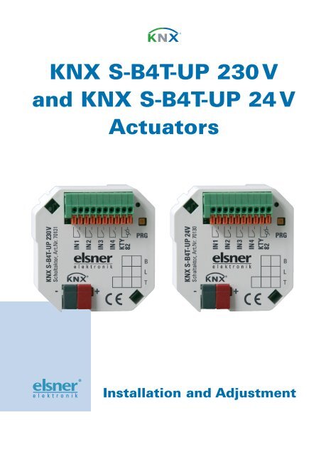
<strong>KNX</strong> S-<strong>B4T</strong>-<strong>UP</strong> <strong>230</strong> V<br />
and <strong>KNX</strong> S-<strong>B4T</strong>-<strong>UP</strong> 24 V<br />
<strong>Actuator</strong>s<br />
Installation and Adjustment
Product Description .......................................................................................... 3<br />
Technical data...............................................................................................................3<br />
<strong>Structure</strong> <strong>of</strong> <strong>Actuator</strong> <strong>KNX</strong> S-<strong>B4T</strong>-<strong>UP</strong> <strong>230</strong> V <strong>AC</strong> ...........................................................5<br />
<strong>Structure</strong> <strong>of</strong> <strong>Actuator</strong> <strong>KNX</strong> S-<strong>B4T</strong>-<strong>UP</strong> 24 V DC .............................................................5<br />
Installation and Commissioning....................................................................................6<br />
Connection ........................................................................................................................................... 6<br />
Notes on installation............................................................................................................................ 6<br />
Transmission protocol....................................................................................... 7<br />
Abbreviations................................................................................................................7<br />
Listing <strong>of</strong> all communication objects ............................................................................7<br />
Setting <strong>of</strong> parameters ..................................................................................... 12<br />
General settings ..........................................................................................................12<br />
Control <strong>of</strong> blinds .........................................................................................................13<br />
Blind drive mechanism ..................................................................................................................... 13<br />
Blind control ....................................................................................................................................... 14<br />
Blind automatic.................................................................................................................................. 19<br />
Control <strong>of</strong> roller shutters ............................................................................................23<br />
Roller shutter drive mechanism ....................................................................................................... 23<br />
Roller shutter control......................................................................................................................... 24<br />
Roller shutter automatic.................................................................................................................... 29<br />
Control <strong>of</strong> awnings......................................................................................................33<br />
Awing drive mechanism ................................................................................................................... 33<br />
Awning control................................................................................................................................... 34<br />
Awning automatic.............................................................................................................................. 39<br />
Control <strong>of</strong> windows.....................................................................................................43<br />
Window drive mechanism ................................................................................................................ 43<br />
Window control.................................................................................................................................. 44<br />
Window automatic............................................................................................................................. 49<br />
<strong>Actuator</strong> push button..................................................................................................53<br />
Bus push button ..........................................................................................................55<br />
Scenes.........................................................................................................................59<br />
Temperature sensor ....................................................................................................60<br />
Threshold 1 / 2 (temperature sensor)............................................................................................... 61<br />
Connection options for zero position sensors.............................................................63
<strong>KNX</strong> S-<strong>B4T</strong>-<strong>UP</strong> • from s<strong>of</strong>tware version 1.01, ETS programme version 1.1 • Status: 17/08/2009.<br />
Errors excepted. Subject to technical changes.<br />
Elsner Elektronik GmbH Steuerungs- und Automatisierungstechnik<br />
Herdweg 7 • D-75391 Gechingen • Germany<br />
Phone: +49 (0) 70 56/93 97-0 • Fax: +49 (0) 70 56/93 97-20<br />
info@elsner-elektronik.de • www.elsner-elektronik.de<br />
2
Product Description<br />
The <strong>Actuator</strong> <strong>KNX</strong> S-<strong>B4T</strong>-<strong>UP</strong> controls shadings (blinds, awnings, roller shutters) or<br />
windows. The automatic for this may be provided externally or internally. An internal<br />
automatic <strong>of</strong>fers numerous options for blocking, locking (e. g. master–slave) and priority<br />
settings (e. g. manual–automatic). Scenes may be stored and recalled via the bus.<br />
Four binary inputs may be used for direct operation (e. g. manual push-buttons) or as<br />
bus inputs. There is an additional input for a temperature sensor.<br />
Functions:<br />
• For drive mechanism <strong>of</strong> shading or window<br />
• 4 binary inputs<br />
• 1 temperature sensor input<br />
• 8 channel scene control for operating position (for blinds also slat position)<br />
• Slat tracking for blinds according to the position <strong>of</strong> the sun<br />
• Position memory (operating position) with a 1 bit object (Storage and recall e. g.<br />
with push-button)<br />
• Position feedback (operating position, for blinds also slat position)<br />
• Control by internal or external automatic<br />
• Setting <strong>of</strong> the priority <strong>of</strong> manual or automatic control by time or via<br />
communication object<br />
• Mutual locking <strong>of</strong> two drives by means <strong>of</strong> zero position sensors avoids collisions<br />
e. g. <strong>of</strong> shading and window (master–slave)<br />
• Blocking objects and alarm messages have different priority so that safety<br />
functions always are higher-ranking (e. g. wind blocking)<br />
Configuration is accomplished by means <strong>of</strong> the <strong>KNX</strong> s<strong>of</strong>tware ETS. The programme<br />
file (format VD2) is ready for download on the Elsner Elektronik website under<br />
www.elsner-elektronik.de in the menu "Service".<br />
Technical data<br />
Housing:<br />
Colour:<br />
Mounting:<br />
Plastic material<br />
White<br />
Protection category: IP 20<br />
Dimensions:<br />
Weight:<br />
Ambient temperature:<br />
Ambient air humidity:<br />
Operating voltage:<br />
In-wall (in socket Ø 60 mm, 60 mm deep)<br />
approx. 50 x 51 x 41 (W x H x T, mm)<br />
<strong>230</strong> V version: approx. 90 g<br />
24 V version: approx. 70 g<br />
Operation -20…+70°C, Storage -30…+85°C<br />
5…80% R. H., avoid condensation<br />
Available for <strong>230</strong> V <strong>AC</strong> or for 24 V DC<br />
3
Current:<br />
Output:<br />
Inputs:<br />
Data output:<br />
BCU type:<br />
PEI type: 0<br />
Group addresses: max. 200<br />
Allocations: max. 200<br />
Communication objects: 125<br />
At the bus: 10 mA<br />
At 24 V DC: 40 mA<br />
At <strong>230</strong> V <strong>AC</strong>: 2 mA <strong>AC</strong><br />
1 x Drive mechanism<br />
<strong>230</strong> V version: max. 500 W, fused with micr<strong>of</strong>use T6.3 A<br />
24 V version: max. 50 W<br />
4 x Binary input (for potential-free contacts)<br />
1 x Temperature sensor input (for T-KTY82)<br />
<strong>KNX</strong> +/- bus terminal plug<br />
Own micro controller<br />
The following standards have been considered for the evaluation <strong>of</strong> the product in<br />
terms <strong>of</strong> electro magnetic compatibility:<br />
Transient emissions:<br />
• EN 60730-1:2000 Section EMV (23, 26, H23, H26) (threshold category: B)<br />
• EN 50090-2-2:1996-11 + A1:2002-01 (threshold category: B)<br />
• EN 61000-6-3:2001 (threshold category: B)<br />
Interference resistance:<br />
• EN 60730-1:2000 Section EMV (23, 26, H23, H26)<br />
• EN 50090-2-2:1996-11 + A1:2002-01<br />
• EN 61000-6-1:2004<br />
The product has been tested for the above mentioned standards by an accredited EMV<br />
laboratory.<br />
4
<strong>Structure</strong> <strong>of</strong> <strong>Actuator</strong> <strong>KNX</strong> S-<strong>B4T</strong>-<strong>UP</strong> <strong>230</strong> V <strong>AC</strong><br />
Fig. 1: Front side <strong>of</strong> <strong>KNX</strong> S-<strong>B4T</strong>-<strong>UP</strong> <strong>230</strong> V<br />
1 Connecting plug terminal binary<br />
inputs and temperature sensor<br />
2 Programming LED<br />
3 Programming key (PRG)<br />
4 Inscription space<br />
5 <strong>KNX</strong> plug terminal +/-<br />
Fig. 2: Rear side <strong>of</strong> <strong>KNX</strong> S-<strong>B4T</strong>-<strong>UP</strong> <strong>230</strong> V<br />
1 Connecting plug terminal for<br />
voltage supply and drive mechanism<br />
2 Micr<strong>of</strong>use T6,3 A<br />
<strong>Structure</strong> <strong>of</strong> <strong>Actuator</strong> <strong>KNX</strong> S-<strong>B4T</strong>-<strong>UP</strong> 24 V DC<br />
Fig. 3: Front side <strong>of</strong> <strong>KNX</strong> S-<strong>B4T</strong>-<strong>UP</strong> 24 V<br />
1 Connecting plug terminal binary<br />
inputs and temperature sensor<br />
2 Programming LED<br />
3 Programming key (PRG)<br />
4 Inscription space<br />
5 <strong>KNX</strong> plug terminal +/-<br />
Fig. 4: Rear side <strong>of</strong> <strong>KNX</strong> S-<strong>B4T</strong>-<strong>UP</strong> 24 V<br />
1 Connecting plug terminal for<br />
voltage supply and<br />
drive mechanism<br />
5
Installation and Commissioning<br />
Installation, inspection, commissioning and troubleshooting<br />
<strong>of</strong> the actuators must only be carried out by a competent<br />
electrician.<br />
Disconnect all lines to be assembled, and take safety precautions against accidental<br />
switch-on.<br />
The actuators are exclusively intended for appropriate use. With each inappropriate<br />
change or non-observance <strong>of</strong> the instructions for use, any warranty or guarantee claim<br />
will be void.<br />
After unpacking the device, check immediately for any mechanical damages. In case <strong>of</strong><br />
transport damage, this must immediately notified to the supplier.<br />
If damaged, the actuators must not be put into<br />
operation.<br />
If an operation without risk may supposedly not be guaranteed, the device must be put<br />
out <strong>of</strong> operation and be secured against accidental operation.<br />
The actators must only be operated as stationary system, i.e. only in a fitted state and<br />
after completion <strong>of</strong> all installation and start-up works, and only in the environment<br />
intended for this purpose.<br />
Elsner Elektronik does not assume any liability for changes in standards after<br />
publication <strong>of</strong> this instruction manual.<br />
Connection<br />
The actuators are installed in a flush-type socket. The connection is accomplished by a<br />
<strong>KNX</strong> connection clamp at the <strong>KNX</strong> data bus. Furthermore, a voltage supply (<strong>230</strong> V <strong>AC</strong> or<br />
24 V DC, depending on the version) is necessary. The physical address is allocated by<br />
the <strong>KNX</strong> s<strong>of</strong>tware. For this purpose, the actuator is provided with a programming key<br />
with control LED.<br />
Notes on installation<br />
Never expose actuators to water (rain) or dust. This might damage the electronic<br />
system. A relative air humidity <strong>of</strong> 95% must not be exceeded. Avoid bedwewing.<br />
6
Transmission protocol<br />
Abbreviations<br />
Flags:<br />
C<br />
R<br />
W<br />
T<br />
Communication<br />
Read<br />
Write<br />
Transmit<br />
Listing <strong>of</strong> all communication objects<br />
No. Name Function Flags DP type<br />
0 Manual long-term Input C R W 1.008<br />
1 Manual short-term Input C R W 1.007<br />
2 Manual operation position Input C R W 5.001<br />
3 Manual slat position Input C R W 5.001<br />
4 Automatic long-term Input C R W 1.008<br />
5 Automatic short-term Input C R W 1.007<br />
6 Automatic operation position Input C R W 5.001<br />
7 Automatic slat position Input C R W 5.001<br />
8 Status automatic or manual UINT1 Output C R T 1.002<br />
9 Current operation position UINT8 Output C R T 5.001<br />
10 Current slat position UINT8 Output C R T 5.001<br />
11 Recall / storage <strong>of</strong> scenes Input C R W 18.001<br />
12 Alarm object Input C R W 1.003<br />
13 Blocking object 1 Input C R W 1.003<br />
14 Wind block object Input C R W 1.003<br />
15 Measured value <strong>of</strong> wind block Input C R W 9.005<br />
16 Wind block status Input C R T 1.002<br />
17 Blocking object 2 Input C R W 1.003<br />
18 Rain block object Input C R W 1.003<br />
19 Change from manual to automatic Input C R W 1.002<br />
20 Automatic for blocking object Input C R W 1.003<br />
7
No. Name Function Flags DP type<br />
21 Exterior temperature blocking object UINT1 Input C R W 1.003<br />
22 Exterior temperature block measured value UINT16 Input C R W 9.001<br />
23 Exterior temperature block status UINT1 Output C R T 1.002<br />
24 Dawn object UINT1 Input C R W 1.003<br />
25 Dawn measured value UINT16 Input C R W 9.004<br />
26 Dawn status UINT1 Output C R T 1.002<br />
27 Time control UINT1 Input C R W 1.002<br />
28 Inside temperature release object UINT1 Input C R W 1.003<br />
29 Inside temperature release measured value UINT16 Input C R W 9.001<br />
30 Inside temperature release target value UINT16 Input C R W 9.001<br />
31 Inside temperature release status UINT1 Output C R T 1.002<br />
32 Shading object UINT1 Input C R W 1.003<br />
33 Shading light measured value 1 UINT16 Input C R W 9.004<br />
34 Shading light measured value 2 UINT16 Input C R W 9.004<br />
35 Shading light measured value 3 UINT16 Input C R W 9.004<br />
36 Shading threshold UINT16<br />
Input/Output<br />
37 Shading threshold<br />
1 = Up / 0 = Down<br />
C R W T 9.004<br />
UINT1 Input C R W 1.007<br />
38 Shading threshold Up UINT1 Input C R W 1.017<br />
39 Shading threshold Down UINT1 Input C R W 1.017<br />
40 Shading status UINT1 Output C R T 1.002<br />
41 Shading position learning object UNIT1 Input C R W 1.017<br />
42 Azimuth UINT16 Input C R W 9.*<br />
43 Elevation UINT16 Input C R W 9.*<br />
44 Cold air supply blocking object UINT1 Input C R W 1.003<br />
45 Cold air supply outside temperature<br />
measured value<br />
UINT16 Input C R W 9.001<br />
46 Cold air supply block status UINT1 Output C R T 1.002<br />
47 Coercive ventilation UINT1 Input C R W 1.002<br />
48 Hot air supply blocking object UINT1 Input C R W 1.003<br />
49 Hot air supply inside temperature<br />
measured value<br />
50 Hot air supply outside temperature<br />
measured value<br />
UINT16 Input C R W 9.001<br />
UINT16 Input C R W 9.001<br />
51 Hot air supply block target value UINT16 Input C R W 9.001<br />
52 Hot air supply block status UINT1 Output C R T 1.002<br />
8
No. Name Function Flags DP type<br />
53 Inside temperature opening object UINT1 Input C R W 1.003<br />
54 Inside temperature opening measured<br />
value<br />
UINT16 Input C R W 9.001<br />
55 Inside temperature opening target value UINT16 Input C R W T 9.001<br />
56 Inside temperature opening threshold UINT16<br />
Input/Output<br />
57 Inside temperature opening threshold<br />
1=Up / 0=Down<br />
C R W 9.001<br />
UINT1 Input C R W 1.007<br />
58 Inside temperature opening threshold Up UINT1 Input C R W 1.017<br />
59 Inside temperature opening threshold<br />
Down<br />
UINT1 Input C R W 1.017<br />
60 Inside temperature opening status UINT1 Output C R T 1.002<br />
61 Inside moisture opening object UINT1 Input C R W 1.003<br />
62 UINT16 Input C R W 9.007<br />
63 UINT1 Output C R T 1.002<br />
64 Zero position obtained UINT1 Input C R W 1.002<br />
65 Zero position sensor interference object UINT1 Output C R T 1.002<br />
66 Master zero position status UINT1 Output C R T 1.002<br />
67 Master zero position command UINT1 Output C R T 1.002<br />
68 Slave zero position status UINT1 Input C R W 1.002<br />
69 Master zero position status UINT1 Input C R W 1.002<br />
70 Master zero position command UINT1 Input C R W 1.002<br />
71 Slave zero position status UINT1 Output C R T 1.002<br />
72 Push button 1 long-term UINT1 Output C R T 1.008<br />
73 Push button 1 short-term UINT1 Output C R T 1.007<br />
74 Push button 1 switching UINT1 Input/Output C R W T 1.001<br />
75 Push button 1 dimming relative UINT4 Input/Output C R W T 3.007<br />
76 Push button 1 encoder 8 bit UINT8 Output C R T 5.010<br />
77 Push button 1 encoder temperature UINT16 Output C R T 9.001<br />
78 Push button 1 encoder light UINT16 Output C R T 9.004<br />
79 Push button 1 scene UINT8 Output C R T 18.001<br />
80 Push button 2 long-term UINT1 Output C R T 1.008<br />
81 Push button 2 short-term UINT1 Output C R T 1.007<br />
82 Push button 2 switching UINT1 Input/Output C R W T 1.001<br />
83 Push button 2 dimming relative UINT4 Input/Output C R W T 3.007<br />
84 Push button 2 encoder 8 bit UINT8 Output C R T 5.010<br />
85 Push button 2 encoder temperature UINT16 Output C R T 9.001<br />
9
No. Name Function Flags DP type<br />
86 Push button 2 encoder light UINT16 Output C R T 9.004<br />
87 Push button 2 scene UINT8 Output C R T 18.001<br />
88 Push button 3 long-term UINT1 Output C R T 1.008<br />
89 Push button 3 short-term UINT1 Output C R T 1.007<br />
90 Push button 3 switching UINT1 Input/Output C R W T 1.001<br />
91 Push button 3 dimming relative UINT4 Input/Output C R W T 3.007<br />
92 Push button 3 encoder 8 bit UINT8 Output C R T 5.010<br />
93 Push button 3 encoder temperature UINT16 Output C R T 9.001<br />
94 Push button 3 encoder light UINT16 Output C R T 9.004<br />
95 Push button 3 scene UINT8 Output C R T 18.001<br />
96 Push button 4 long-term UINT1 Output C R T 1.008<br />
97 Push button 4 short-term UINT1 Output C R T 1.007<br />
98 Push button 4 switching UINT1 Input/Output C R W T 1.001<br />
99 Push button 4 dimming relative UINT4 Input/Output C R W T 3.007<br />
100 Push button 4 encoder 8 bit UINT8 Output C R T 5.010<br />
101 Push button 4 encoder temperature UINT16 Output C R T 9.001<br />
102 Push button 4 encoder light UINT16 Output C R T 9.004<br />
103 Push button 4 scene UINT8 Output C R T 18.001<br />
104 Temperature sensor disturbed UINT1 Output C R T 1.002<br />
105 External measured value UINT16 Input C R W 9.001<br />
106 Internal measured value UINT16 Output C R T 9.001<br />
107 Total measured value UINT16 Output C R T 9.001<br />
108 Requirement min./max. temperature UINT1 Input C R W 1.017<br />
109 Lowest temperature measured value UINT16 Output C R T 9.001<br />
110 Highest temperature measured value UINT16 Output C R T 9.001<br />
111 Reset min./max. temperature UINT1 Input C R W 1.017<br />
112 Temperature threshold value 1 UINT16<br />
Input/Output<br />
113 Temperature threshold value 1<br />
1 = Up / 0 = Down<br />
C R W T 9.001<br />
UINT1 Input C R W 1.007<br />
114 Temperature threshold value 1 Up UINT1 Input C R W 1.017<br />
115 Temperature threshold value 1 Down UINT1 Input C R W 1.017<br />
116 Temperature threshold value 1 blocking<br />
object<br />
117 Temperature threshold value 1 switching<br />
output<br />
UINT1 Input C R W 1.003<br />
UINT1 Output C R T 1.002<br />
10
No. Name Function Flags DP type<br />
118 Temperature threshold value 2 UINT16<br />
Input/Output<br />
119 Temperature threshold value 2<br />
1 = Up / 0 = Down<br />
C R W T 9.001<br />
UINT1 Input C R W 1.007<br />
120 Temperature threshold value 2 Up UINT1 Input C R W 1.017<br />
121 Temperature threshold value 2 Down UINT1 Input C R W 1.017<br />
122 Temperature threshold value 2 blocking<br />
object<br />
123 Temperature threshold value 2 switching<br />
output<br />
124 S<strong>of</strong>tware version Readable<br />
UINT1 Input C R W 1.003<br />
UINT1 Output C R T 1.002<br />
11
Setting <strong>of</strong> parameters<br />
General settings<br />
<strong>Actuator</strong> controls<br />
Use scenes<br />
(see chapter „Scenes“)<br />
Use input 1 / 2 / 3<br />
Use input 4<br />
Send malfunction message<br />
in case <strong>of</strong> defect zero position sensor<br />
(only if „Use input 4 as zero position sensor"<br />
has been selected)<br />
Transmission delay <strong>of</strong> the threshold values<br />
after restoration <strong>of</strong> voltage<br />
Transmission delay <strong>of</strong> switching/status<br />
outputs after restoration <strong>of</strong> voltage<br />
Use temperature sensor<br />
(see chapter „Temperature sensor“)<br />
Blind • Roller shutter • Awning • Window<br />
No • Yes<br />
No • as bus push button • as actuator push<br />
button<br />
No • as bus push button • as actuator push<br />
button • as zero position sensor<br />
No • Yes<br />
5 sec … 2 h<br />
5 sec … 2 h<br />
No • Yes<br />
12
Control <strong>of</strong> blinds<br />
„<strong>Actuator</strong> controls Blind“ has been selected for the “General settings”.<br />
Blind drive mechanism<br />
This is to indicate the specific features <strong>of</strong> the connected drive mechanism.<br />
Exchange Up/Down<br />
No • Yes<br />
Runtime DOWN in sec 0 … 320<br />
Runtime <strong>UP</strong> in sec 0 … 320<br />
Runtime zero position in 0.1 sec 0 … 255<br />
Duration <strong>of</strong> steps in 10 msec 10 … 100<br />
Number <strong>of</strong> steps <strong>of</strong> slats 1 … 255<br />
Duration <strong>of</strong> steps x number <strong>of</strong> steps = turning time <strong>of</strong> slats<br />
Pause time for direction change in 0.1 sec 0 … 100<br />
Accomplish reference run<br />
Use slats<br />
Send drive position after change<br />
No • Yes<br />
never • only after positioning run •<br />
after each run<br />
No • Yes<br />
13
If “Accomplish reference run: Yes“ has been selected:<br />
in case <strong>of</strong> more than<br />
operations before one auto. position run<br />
1 … 255<br />
The reference run is always accomplished in the direction <strong>of</strong> the safe position.<br />
If “Send drive position after change: Yes” has been selected:<br />
Transmission delay <strong>of</strong> the position in 0.1 sec 0 … 50<br />
Blind control<br />
The setting options correspond with those <strong>of</strong> a roller shutter or an awning.<br />
Use operating range limit<br />
Behaviour in case <strong>of</strong> bus voltage breakdown<br />
Use monitoring <strong>of</strong> alarm and blocking objects<br />
No • Yes<br />
No action • Stop •<br />
<strong>UP</strong>-command • DOWN-command<br />
No • Yes<br />
Operating range limit<br />
The operating range limit is used in order to avoid that two units collide with each other<br />
(e.g. an awning and a window which is about to open).<br />
One <strong>of</strong> two drive mechanisms is prioritised and is parameterised as master and the<br />
other one as slave. By means <strong>of</strong> zero position sensors, both actuators know the own<br />
current status and the current status <strong>of</strong> the other one. This one is either “in a safe<br />
position“ or “not in a safe position“. The safe position is reached as soon as the drive<br />
14
mechanism is in a sector where a collision is not possible (for an awning, for example,<br />
this might be an extension <strong>of</strong> 0 to 30%). In order to report the safe position <strong>of</strong> the drive<br />
mechanism, either a zero position sensor (e.g. final position switch or light barrier) may<br />
be connected at input 4 (IN4) <strong>of</strong> the actuator <strong>KNX</strong> S-<strong>B4T</strong>-<strong>UP</strong>, or the actuator receives the<br />
message <strong>of</strong> its zero position sensor by the bus (see graphic in chapter “Connection<br />
options for zero position sensors”).<br />
Before the drive mechanism <strong>of</strong> the master actuator is moved, the slave actuator<br />
receives the command to move its drive mechanism to the safe position. As a<br />
consequence, the slave remains in safe position or it moves back if it is not within the<br />
safe range.<br />
The master actuator knows from the communication object „Slave zero position status”<br />
whether the drive mechanism connected to the slave actuator is already in a safe<br />
position (then the master moves immediately) or not (then the master waits). Only if the<br />
master actuator is informed that the slave drive mechanism is in a safe position, it<br />
moves its drive mechanism beyond its own safe position.<br />
Example:<br />
The ventilation with the window shall take priority over the shading with the awning.<br />
Therefore, the window is parameterised as master, the awning as slave. Both are<br />
provided with a zero position sensor which reports whether the drive mechanism is in a<br />
safe position or not.<br />
The awning is now extended and the window shall be opened. The window knows the<br />
status <strong>of</strong> the awning (“not safe position”) and therefore submits a master command to<br />
the awning. This is the signal for the awning, to retract a little bit. As soon as the awning<br />
has reached a safe position, there is an according feedback signal <strong>of</strong> the zero position<br />
sensor <strong>of</strong> the awning. Only now the window opens.<br />
Master and slave regularly exchange their positions (“safe“<br />
or “not safe”). By means <strong>of</strong> the monitoring period, you may<br />
adjust the frequency <strong>of</strong> information retrieval. The selected<br />
period should be shorter than the period which the monitored<br />
drive mechanism needs to travel from the limit <strong>of</strong> the safe<br />
range (last reported safe position) to a position where there is<br />
risk <strong>of</strong> collision.<br />
If the drive mechanism does not receive a master/slave or zero position object, it moves<br />
to the safe position. The same holds true for a bus voltage breakdown or for a<br />
malfunction message from the zero position sensor (is valid for the parameterisation as<br />
master and as slave).<br />
15
If “Use operating range limit: Yes“ has been selected:<br />
<strong>Actuator</strong> is<br />
Master • Slave<br />
If “<strong>Actuator</strong> is Master“ has been selected:<br />
(Zero position sensor at bus)<br />
<strong>Actuator</strong> is<br />
Master<br />
Transmission repetition for master command<br />
in sec<br />
Monitoring period for zero position object and<br />
slave status in sec<br />
1 … 255<br />
1 … 255<br />
(Zero position sensor at input 4 <strong>of</strong> actuator)<br />
<strong>Actuator</strong> is<br />
Transmission repetition for master and status<br />
command in sec<br />
Master<br />
1 … 255<br />
Monitoring period for slave status in sec 1 … 255<br />
If “<strong>Actuator</strong> is Slave“ has been selected:<br />
(Zero position sensor at bus)<br />
<strong>Actuator</strong> is<br />
Slave<br />
Monitoring period for zero position object and<br />
master status in sec<br />
Travel position for slave in % if<br />
input “Master zero position command“ = 1<br />
1 … 255<br />
0 … 100<br />
(Zero position sensor at input 4 <strong>of</strong> actuator)<br />
<strong>Actuator</strong> is<br />
Slave<br />
Transmission repetition for slave status in sec 1 … 255<br />
Monitoring period for master status in sec 1 … 255<br />
Travel position for slave in % if<br />
input “Master zero position command“ = 1<br />
0 … 100<br />
Monitoring <strong>of</strong> alarm and blocking objects<br />
If “Monitoring <strong>of</strong> alarm and blocking objects: Yes” has been selected:<br />
Monitoring period for<br />
5 sec … 2h<br />
alarm/blocking objects<br />
Behaviour in case <strong>of</strong> non-receipt <strong>of</strong> an<br />
alarm/blocking object<br />
Stop • <strong>UP</strong>-command • DOWN-command<br />
The priorities <strong>of</strong> the following functions correspond with the order in the programme!<br />
Note: Alarm and blocking objects block at 1<br />
Alarm object<br />
Use alarm object<br />
No • Yes<br />
16
If “Use alarm object: Yes“ has been selected:<br />
Use alarm object<br />
If alarm object value = 1<br />
If alarm object value = 0<br />
In case <strong>of</strong> manual operation before and after<br />
alarm<br />
In case <strong>of</strong> automatic operation after alarm<br />
Value <strong>of</strong> the object before 1st communication<br />
and restoration <strong>of</strong> bus voltage<br />
Yes<br />
no action • Stop •<br />
<strong>UP</strong>-command • DOWN-command<br />
no action • move to last position<br />
Follow automatic<br />
0 • 1<br />
Blocking object 1 / 2<br />
Use blocking object 1<br />
Use blocking object 2<br />
No • Yes<br />
No • Yes<br />
If “Use blocking object 1 / 2: Yes“ has been selected:<br />
Settings see ”Alarm object”<br />
Wind block<br />
Use wind block<br />
No • Yes<br />
If “Use wind block: Yes“ has been selected:<br />
Note: In case <strong>of</strong> block, the blind moves up.<br />
Type <strong>of</strong> input object<br />
1 Bit • 16 Bit<br />
If “Type <strong>of</strong> input object 1 Bit“ has been selected:<br />
Use wind block<br />
Yes<br />
Type <strong>of</strong> input object<br />
Waiting time in safe position in min<br />
after wind block<br />
Behaviour after waiting period:<br />
In case <strong>of</strong> manual operation<br />
before and after wind alarm<br />
In case <strong>of</strong> automatic operation after blocking<br />
1 Bit<br />
0 … 255<br />
no action • move to last position<br />
follow automatic<br />
If “Type <strong>of</strong> input object 16 bit“ has been selected:<br />
Use wind block<br />
Yes<br />
Type <strong>of</strong> input object<br />
From wind speed in m/s<br />
up-command<br />
Waiting time in safe position in min<br />
after wind block<br />
Behaviour after waiting period:<br />
In case <strong>of</strong> manual operation<br />
before and after wind alarm<br />
16 Bit<br />
2 … 30<br />
0 … 255<br />
no action • move to previous position<br />
17
In case <strong>of</strong> automatic operation after blocking<br />
Send current block status<br />
follow automatic<br />
No • Yes<br />
Priority <strong>of</strong> rain block or manual operation<br />
The following priorities must be observed:<br />
Rain prior to manual •<br />
Manual prior to rain<br />
Rain block<br />
Use rain block<br />
No • Yes<br />
If “Use rain block: Yes“ has been selected:<br />
Note: In case <strong>of</strong> block, the blind moves up.<br />
Waiting time in safe position in min<br />
0 … 20<br />
after rain block<br />
Behaviour after waiting period:<br />
In case <strong>of</strong> manual operation<br />
before and after block<br />
In case <strong>of</strong> automatic operation after blocking<br />
no action • move to last position<br />
follow automatic<br />
Change from manual to automatic<br />
Manual changes to automatic after<br />
Waiting time in min<br />
(only if “…expiration <strong>of</strong> waiting period“ has<br />
been selected)<br />
Change to automatic for object value<br />
(only if “receipt <strong>of</strong> object…“ has been<br />
selected)<br />
• Expiration <strong>of</strong> waiting period<br />
• Receipt <strong>of</strong> an object<br />
• Receipt <strong>of</strong> an object or expiration <strong>of</strong> waiting<br />
period<br />
1 … 255<br />
0 • 1 • 0 or 1<br />
Further settings<br />
Use automatic blocking object<br />
No • Yes<br />
If “Use automatic blocking object: Yes” has been selected:<br />
Use automatic blocking object<br />
Yes<br />
Automatic is blocked at 0 • 1<br />
Value <strong>of</strong> the blocking object after<br />
restoration <strong>of</strong> voltage<br />
0 • 1<br />
Operation mode after restoration <strong>of</strong> voltage<br />
Send status object<br />
Automatic • Manual<br />
1 for automatic | 0 for manual •<br />
0 for automatic | 1 for manual •<br />
18
Transmission delay <strong>of</strong> the status output<br />
automatic or manual in 0.1 sec<br />
Type <strong>of</strong> automatic<br />
0 … 50<br />
external automatic • internal automatic<br />
Blind automatic<br />
For “Blind control“ “Type <strong>of</strong> automatic: internal automatic“ has been selected.<br />
Outdoor temperature block<br />
Use outdoor temperature block<br />
No • Yes<br />
If “Use outdoor temperature block: Yes“ has been selected:<br />
Use outdoor temperature block<br />
Yes<br />
Type <strong>of</strong> temperature input object<br />
1 Bit • 16 Bit<br />
If “Type <strong>of</strong> temperature input 1 bit“ has been selected:<br />
Shading is permitted if bit is 0, and it is blocked if bit is 1.<br />
If “Type <strong>of</strong> temperature input 16 bit“ has been selected:<br />
Shading is blocked if the measured value is smaller than the threshold value, and it is<br />
permitted if the measured value is larger than the threshold value plus hysteresis.<br />
Threshold in 0.1°C -300 … 800<br />
Hysteresis in 0.1°C 1 … 100<br />
Send current blocking status<br />
No • Yes<br />
19
Dawn control / time control<br />
Use dawn and time control<br />
• No<br />
• only dawn control<br />
• only time control<br />
• both (OR gating)<br />
If dawn control or time control or both are used:<br />
Type <strong>of</strong> dawn input object<br />
1 Bit • 16 Bit<br />
If “Type <strong>of</strong> dawn input object 16 bit“ has been selected:<br />
Type <strong>of</strong> dawn input object<br />
16 Bit<br />
Dawn threshold value in lux 1 … 1000<br />
Switching delay<br />
1 minute<br />
Send current dawn status<br />
No • Yes<br />
Time control is accomplished by a communication object.<br />
Release <strong>of</strong> indoor temperature<br />
Use indoor temperature release<br />
No • Yes<br />
If “Use indoor temperature release: Yes“ has been selected:<br />
Type <strong>of</strong> input object<br />
1 bit • 16 bit • 16 bit target/actual temperature<br />
If “Type <strong>of</strong> input object 1 bit“ has been selected:<br />
Shading is permitted if bit is 1, and it is blocked if bit is 0.<br />
If “Type <strong>of</strong> input object 16 bit“ has been selected:<br />
Shading is permitted if the measured value is larger than or equal to the threshold, and<br />
it is blocked if the measured value is smaller than the threshold minus hysteresis.<br />
Threshold in 0.1°C -300 … 800<br />
Hysteresis in 0.1°C 1 … 100<br />
Send current block status<br />
No • Yes<br />
If “Type <strong>of</strong> input object 16 bit target/actual temperature“ has been selected:<br />
Shading is permitted if the measured value is larger than or equal to the target value<br />
plus the target-actual-difference, and it is blocked if the measured value is smaller than<br />
the target value plus the target-actual-difference minus hysteresis.<br />
The target value is provided by the communication object.<br />
Target-actual difference in 0.1 °C 1 … 100<br />
Hysteresis in 0.1°C 1 … 100<br />
Send current block status<br />
No • Yes<br />
Shading automatic<br />
Use shading automatic<br />
No • Yes<br />
20
If “Use shading automatic: Yes“ has been selected:<br />
Brightness:<br />
--------------------------------------<br />
Type <strong>of</strong> shading input<br />
1 x 1 Bit • 1 x 16 Bit • 2 x 16 Bit • 3 x 16 Bit<br />
Up-movement delay in min 0 … 255<br />
Down-movement delay in min 0 … 30<br />
If “Type <strong>of</strong> shading input 1 x 16 bit / 2 x 16 bit / 3 x 16 bit“ has been selected:<br />
The measured values <strong>of</strong> one, two or three light sensors may be evaluated. The highest<br />
value is the value which is always relevant for the reaction.<br />
Shading threshold value standard by<br />
Parameter • Communication object<br />
If “Shading threshold standard by parameter” has been selected:<br />
Shading threshold value standard by<br />
Parameter<br />
Shading threshold value in klux 0 … 100<br />
Up-movement delay in min 0 … 255<br />
Down-movement delay in min 0 … 30<br />
Send current shading status<br />
No • Yes<br />
If “Shading threshold standard by communication object” has been selected:<br />
Shading threshold value standard by<br />
The last-communicated value shall be<br />
maintained<br />
Starting threshold value in klux<br />
valid until 1st communication<br />
Type <strong>of</strong> threshold value change<br />
Step size in klux<br />
(only in case <strong>of</strong> “Increment/decrement with<br />
comm. object”)<br />
Communication object<br />
• not<br />
• after restoration <strong>of</strong> voltage<br />
• after restoration <strong>of</strong> voltage and programming<br />
0 … 100<br />
• Absolute value with 16 bit comm. object<br />
• Increment/decrement with one comm. object<br />
• Increment/decrement with two comm.objects<br />
1 … 5<br />
Up-movement delay in min 0 … 255<br />
Down-movement delay in min 0 … 30<br />
Send current shading status<br />
No • Yes<br />
Position <strong>of</strong> the sun:<br />
--------------------------------------<br />
Evaluate the position <strong>of</strong> the sun<br />
No • Yes<br />
If “Evaluate <strong>of</strong> the position <strong>of</strong> the sun: Yes“ has been selected:<br />
Evaluate the position <strong>of</strong> the sun<br />
Yes<br />
21
Position <strong>of</strong> the sun is defined by<br />
• discrete values <strong>of</strong> azimuth and elevation<br />
• directions (in terms <strong>of</strong> azimuth/elevation)<br />
If “Position <strong>of</strong> the sun is defined by discrete values“ has been selected:<br />
Azimuth from 0 … 360<br />
Azimuth up to 0 … 360<br />
Elevation from 0 … 90<br />
Elevation up to 0 … 90<br />
If “Position <strong>of</strong> the sun is defined by directions“ has been selected:<br />
Direction • East (azimuth: 0° … 180°)<br />
• Southeast (azimuth: 45° … 225°)<br />
• South (azimuth: 90° … 270°)<br />
• Southwest (azimuth: 135° … 315°)<br />
• West (azimuth: 180° … 360°)<br />
Slat and travel position:<br />
--------------------------------------<br />
Note: Slats are closed at 100% and horizontal at 50%.<br />
Shall slats follow elevation<br />
No • Yes<br />
If “Shall slats follow elevation: No” has been selected:<br />
Shall slats follow elevation<br />
No<br />
Slat position in % 0 … 100<br />
Blind position in % 0 … 100<br />
Use learning object for new shading positions No • Yes<br />
If “Use learning object for new shading positions: Yes” has been selected, a new<br />
shading position may be learned (travel position and slat angle). For this purpose, the<br />
shading is moved manually to any position first and learns by means <strong>of</strong> 41 “Shading<br />
position learning object“. In case <strong>of</strong> sun, the automatic then moves to the learned<br />
position.<br />
If “Shall slats follow elevation: Yes” has been selected, the elevation angles and<br />
the according slat positions may be set. Three elevation angles may be set:<br />
in case <strong>of</strong> elevation below (in degree) 0 … 90<br />
Slat position in % 0 … 100<br />
otherwise<br />
Slat position in % 0 … 100<br />
Blind position in % 0 … 100<br />
Use learning object for new shading positions<br />
No • Yes<br />
If “Use learning object for new shading positions: Yes” has been selected, a new<br />
shading position may be learned (only travel position, slats turn to elevation). For this<br />
purpose, the shading is moved manually to any position first and learns by means <strong>of</strong> 41<br />
22
“Shading position learning object“. In case <strong>of</strong> sun, the automatic then moves to the<br />
learned position.<br />
Control <strong>of</strong> roller shutters<br />
For “General settings“, “<strong>Actuator</strong> controls roller shutter“ has been selected.<br />
Roller shutter drive mechanism<br />
This is to indicate the specific features <strong>of</strong> the connected drive mechanism.<br />
Exchange <strong>UP</strong>/DOWN<br />
No • Yes<br />
Runtime <strong>UP</strong> in sec 0 … 320<br />
Runtime DOWN in sec 0 … 320<br />
Pause time for direction change in 0.1 sec 0 … 100<br />
Accomplish reference run<br />
No • Yes<br />
Send drive position after change<br />
No • Yes<br />
If “Accomplish reference run: Yes“ has been selected:<br />
in case <strong>of</strong> more than<br />
1 … 255<br />
runs before one auto. position operation<br />
The reference run is always accomplished in the direction <strong>of</strong> the safe position.<br />
If “Send drive position after change: Yes” has been selected:<br />
Transmission delay <strong>of</strong> the position in 0.1 sec 0 … 50<br />
23
Roller shutter control<br />
The setting options correspond to those <strong>of</strong> blinds or awnings.<br />
Use operating range limit<br />
Behaviour in case <strong>of</strong> bus voltage breakdown<br />
Use monitoring <strong>of</strong> alarm and blocking objects<br />
No • Yes<br />
No action • Stop •<br />
<strong>UP</strong>-command • DOWN-command<br />
No • Yes<br />
Operating range limit<br />
The operating range limit is used in order to avoid that two units collide with each other<br />
(e.g. an awning and a window which is about to open).<br />
One <strong>of</strong> two drive mechanisms is prioritised and is parameterised as master and the<br />
other one as slave. By means <strong>of</strong> zero position sensors, both actuators know the own<br />
current status and the current status <strong>of</strong> the other one. This one is either “in a safe<br />
position“ or “not in a safe position“. The safe position is reached as soon as the drive<br />
mechanism is in a sector where a collision is not possible (for an awning, for example,<br />
this might be an extension <strong>of</strong> 0 to 30%). In order to report the safe position <strong>of</strong> the drive<br />
mechanism, either a zero position sensor (e.g. final position switch or light barrier) may<br />
be connected at input 4 (IN4) <strong>of</strong> the actuator <strong>KNX</strong> S-<strong>B4T</strong>-<strong>UP</strong>, or the actuator receives the<br />
message <strong>of</strong> its zero position sensor by the bus (see graphic in chapter “Connection<br />
options for zero position sensors”).<br />
Before the drive mechanism <strong>of</strong> the master actuator is moved, the slave actuator<br />
receives the command to move its drive mechanism to the safe position. As a<br />
24
consequence, the slave remains in safe position or it moves back if it is not within the<br />
safe range.<br />
The master actuator knows from the communication object „Slave zero position status”<br />
whether the drive mechanism connected to the slave actuator is already in a safe<br />
position (then the master moves immediately) or not (then the master waits). Only if the<br />
master actuator is informed that the slave drive mechanism is in a safe position, it<br />
moves its drive mechanism beyond its own safe position.<br />
You can see an example in the chapter “Blind control: Operating range limit”.<br />
Master and slave regularly exchange their positions (“safe“<br />
or “not safe”). By means <strong>of</strong> the monitoring period, you may<br />
adjust the frequency <strong>of</strong> information retrieval. The selected<br />
period should be shorter than the period which the monitored<br />
drive mechanism needs to travel from the limit <strong>of</strong> the safe<br />
range (last reported safe position) to a position where there is<br />
risk <strong>of</strong> collision.<br />
If the drive mechanism does not receive a master/slave or zero position object, it moves<br />
to the safe position. The same holds true for a bus voltage breakdown or for a<br />
malfunction message from the zero position sensor (is valid for the parameterisation as<br />
master and as slave).<br />
If “Use operating range limit: Yes“ has been selected:<br />
<strong>Actuator</strong> is<br />
Master • Slave<br />
If “<strong>Actuator</strong> is Master“ has been selected:<br />
(Zero position sensor at bus)<br />
<strong>Actuator</strong> is<br />
Master<br />
Transmission repetition for master command<br />
in sec<br />
Monitoring period for zero position object and<br />
slave status in sec<br />
1 … 255<br />
1 … 255<br />
(Zero position sensor at input 4 <strong>of</strong> actuator)<br />
<strong>Actuator</strong> is<br />
Transmission repetition for master and status<br />
command in sec<br />
Master<br />
1 … 255<br />
Monitoring period for slave status in sec 1 … 255<br />
If “<strong>Actuator</strong> is Slave“ has been selected:<br />
(Zero position sensor at bus)<br />
<strong>Actuator</strong> is<br />
Slave<br />
Monitoring period for zero position object and<br />
master status in sec<br />
1 … 255<br />
25
Travel position for slave in % if<br />
input “Master zero position command“ = 1<br />
0 … 100<br />
(Zero position sensor at input 4 <strong>of</strong> actuator)<br />
<strong>Actuator</strong> is<br />
Slave<br />
Transmission repetition for slave status in sec 1 … 255<br />
Monitoring period for master status in sec 1 … 255<br />
Travel position for slave in % if<br />
input “Master zero position command“ = 1<br />
0 … 100<br />
Monitoring <strong>of</strong> alarm and blocking objects<br />
If “Monitoring <strong>of</strong> alarm and blocking objects: Yes” has been selected:<br />
Monitoring period for<br />
5 sec … 2h<br />
alarm/blocking objects<br />
Behaviour in case <strong>of</strong> non-receipt <strong>of</strong> an<br />
alarm/blocking object<br />
Stop • <strong>UP</strong>-command • DOWN-command<br />
The priorities <strong>of</strong> the following functions correspond with the order in the programme!<br />
Note: Alarm and blocking objects block at 1<br />
Alarm object<br />
Use alarm object<br />
No • Yes<br />
If “Use alarm object: Yes“ has been selected:<br />
Use alarm object<br />
Yes<br />
If alarm object value = 1<br />
If alarm object value = 0<br />
In case <strong>of</strong> manual operation before and after<br />
alarm<br />
In case <strong>of</strong> automatic operation after alarm<br />
Value <strong>of</strong> the object before 1st communication<br />
and restoration <strong>of</strong> bus voltage<br />
no action • Stop •<br />
<strong>UP</strong>-command • DOWN-command<br />
no action • move to last position<br />
Follow automatic<br />
0 • 1<br />
Blocking object 1 / 2<br />
Use blocking object 1<br />
Use blocking object 2<br />
No • Yes<br />
No • Yes<br />
If “Use blocking object 1 / 2: Yes“ has been selected:<br />
Settings see ”Alarm object”<br />
Wind block<br />
Use wind block<br />
No • Yes<br />
26
If “Use wind block: Yes“ has been selected:<br />
Note: In case <strong>of</strong> block, the roller shutter moves up.<br />
Type <strong>of</strong> input object<br />
1 Bit • 16 Bit<br />
If “Type <strong>of</strong> input object 1 Bit“ has been selected:<br />
Use wind block<br />
Yes<br />
Type <strong>of</strong> input object<br />
Waiting time in safe position in min<br />
after wind block<br />
Behaviour after waiting period:<br />
In case <strong>of</strong> manual operation<br />
before and after wind alarm<br />
In case <strong>of</strong> automatic operation after blocking<br />
1 Bit<br />
0 … 255<br />
no action • move to last position<br />
follow automatic<br />
If “Type <strong>of</strong> input object 16 bit“ has been selected:<br />
Use wind block<br />
Yes<br />
Type <strong>of</strong> input object<br />
From wind speed in m/s<br />
up-command<br />
Waiting time in safe position in min<br />
after wind block<br />
Behaviour after waiting period:<br />
In case <strong>of</strong> manual operation<br />
before and after wind alarm<br />
In case <strong>of</strong> automatic operation after blocking<br />
Send current block status<br />
16 Bit<br />
2 … 30<br />
0 … 255<br />
no action • move to previous position<br />
follow automatic<br />
No • Yes<br />
Priority <strong>of</strong> rain block or manual operation<br />
The following priorities must be observed:<br />
Rain prior to manual •<br />
Manual prior to rain<br />
Rain block<br />
Use rain block<br />
No • Yes<br />
If “Use rain block: Yes“ has been selected:<br />
Note: In case <strong>of</strong> block, the roller shutter moves up.<br />
Waiting time in safe position in min<br />
0 … 20<br />
after rain block<br />
Behaviour after waiting period:<br />
In case <strong>of</strong> manual operation<br />
before and after block<br />
In case <strong>of</strong> automatic operation after blocking<br />
no action • move to last position<br />
follow automatic<br />
27
Change from manual to automatic<br />
Manual changes to automatic after<br />
Waiting time in min<br />
(only if “…expiration <strong>of</strong> waiting period“ has<br />
been selected)<br />
Change to automatic for object value<br />
(only if “receipt <strong>of</strong> object…“ has been<br />
selected)<br />
• Expiration <strong>of</strong> waiting period<br />
• Receipt <strong>of</strong> an object<br />
• Receipt <strong>of</strong> an object or expiration <strong>of</strong> waiting<br />
period<br />
1 … 255<br />
0 • 1 • 0 or 1<br />
Further settings<br />
Use automatic blocking object<br />
No • Yes<br />
If “Use automatic blocking object: Yes” has been selected:<br />
Use automatic blocking object<br />
Yes<br />
Automatic is blocked at 0 • 1<br />
Value <strong>of</strong> the blocking object after<br />
restoration <strong>of</strong> voltage<br />
0 • 1<br />
Operation mode after restoration <strong>of</strong> voltage<br />
Send status object<br />
Transmission delay <strong>of</strong> the status output<br />
automatic or manual in 0.1 sec<br />
Type <strong>of</strong> automatic<br />
Automatic • Manual<br />
1 for automatic | 0 for manual •<br />
0 for automatic | 1 for manual •<br />
0 … 50<br />
external automatic • internal automatic<br />
28
Roller shutter automatic<br />
For “Roller shutter control“, “Type <strong>of</strong> automatic: internal automatic“ has been selected.<br />
Outdoor temperature block<br />
Use outdoor temperature block<br />
No • Yes<br />
If “Use outdoor temperature block: Yes“ has been selected:<br />
Use outdoor temperature block<br />
Yes<br />
Type <strong>of</strong> temperature input object<br />
1 Bit • 16 Bit<br />
If “Type <strong>of</strong> temperature input 1 bit“ has been selected:<br />
Shading is permitted if bit is 0, and it is blocked if bit is 1.<br />
If “Type <strong>of</strong> temperature input 16 bit“ has been selected:<br />
Shading is blocked if the measured value is smaller than the threshold value, and it is<br />
permitted if the measured value is larger than the threshold value plus hysteresis.<br />
Threshold in 0.1°C -300 … 800<br />
Hysteresis in 0.1°C 1 … 100<br />
Send current blocking status<br />
No • Yes<br />
29
Dawn control / time control<br />
Use dawn and time control<br />
• No<br />
• only dawn control<br />
• only time control<br />
• both (OR gating)<br />
If dawn control or time control or both are used:<br />
Type <strong>of</strong> dawn input object<br />
1 Bit • 16 Bit<br />
If “Type <strong>of</strong> dawn input object 16 bit“ has been selected:<br />
Type <strong>of</strong> dawn input object<br />
16 Bit<br />
Dawn threshold value in lux 1 … 1000<br />
Switching delay<br />
1 minute<br />
Send current dawn status<br />
No • Yes<br />
Time control is accomplished by a communication object.<br />
Release <strong>of</strong> indoor temperature<br />
Use indoor temperature release<br />
No • Yes<br />
If “Use indoor temperature release: Yes“ has been selected:<br />
Type <strong>of</strong> input object<br />
1 bit • 16 bit • 16 bit target/actual temperature<br />
If “Type <strong>of</strong> input object 1 bit“ has been selected:<br />
Shading is permitted if bit is 1, and it is blocked if bit is 0.<br />
If “Type <strong>of</strong> input object 16 bit“ has been selected:<br />
Shading is permitted if the measured value is larger than or equal to the threshold, and<br />
it is blocked if the measured value is smaller than the threshold minus hysteresis.<br />
Threshold in 0.1°C -300 … 800<br />
Hysteresis in 0.1°C 1 … 100<br />
Send current block status<br />
No • Yes<br />
If “Type <strong>of</strong> input object 16 bit target/actual temperature“ has been selected:<br />
Shading is permitted if the measured value is larger than or equal to the target value<br />
plus the target-actual-difference, and it is blocked if the measured value is smaller than<br />
the target value plus the target-actual-difference minus hysteresis.<br />
The target value is provided by the communication object.<br />
Target-actual difference in 0.1 °C 1 … 100<br />
Hysteresis in 0.1°C 1 … 100<br />
Send current block status<br />
No • Yes<br />
Shading automatic<br />
Use shading automatic<br />
No • Yes<br />
30
If “Use shading automatic: Yes“ has been selected:<br />
Brightness:<br />
--------------------------------------<br />
Type <strong>of</strong> shading input<br />
1 x 1 Bit • 1 x 16 Bit • 2 x 16 Bit • 3 x 16 Bit<br />
Up-movement delay in min 0 … 255<br />
Down-movement delay in min 0 … 30<br />
If “Type <strong>of</strong> shading input 1 x 16 bit / 2 x 16 bit / 3 x 16 bit“ has been selected:<br />
The measured values <strong>of</strong> one, two or three light sensors may be evaluated. The highest<br />
value is the value which is always relevant for the reaction.<br />
Shading threshold value standard by<br />
Parameter • Communication object<br />
If “Shading threshold standard by parameter” has been selected:<br />
Shading threshold value standard by<br />
Parameter<br />
Shading threshold value in klux 0 … 100<br />
Up-movement delay in min 0 … 255<br />
Down-movement delay in min 0 … 30<br />
Send current shading status<br />
No • Yes<br />
If “Shading threshold standard by communication object” has been selected:<br />
Shading threshold value standard by<br />
The last-communicated value shall be<br />
maintained<br />
Starting threshold value in klux<br />
valid until 1st communication<br />
Type <strong>of</strong> threshold value change<br />
Step size in klux<br />
(only in case <strong>of</strong> “Increment/decrement with<br />
comm. object”)<br />
Communication object<br />
• not<br />
• after restoration <strong>of</strong> voltage<br />
• after restoration <strong>of</strong> voltage and programming<br />
0 … 100<br />
• Absolute value with 16 bit comm. object<br />
• Increment/decrement with one comm. object<br />
• Increment/decrement with two comm.objects<br />
1 … 5<br />
Up-movement delay in min 0 … 255<br />
Down-movement delay in min 0 … 30<br />
Send current shading status<br />
No • Yes<br />
Position <strong>of</strong> the sun:<br />
--------------------------------------<br />
Evaluate the position <strong>of</strong> the sun<br />
No • Yes<br />
If “Evaluate <strong>of</strong> the position <strong>of</strong> the sun: Yes“ has been selected:<br />
Evaluate the position <strong>of</strong> the sun<br />
Yes<br />
31
Position <strong>of</strong> the sun is defined by<br />
• discrete values <strong>of</strong> azimuth and elevation<br />
• directions (in terms <strong>of</strong> azimuth/elevation)<br />
If “Position <strong>of</strong> the sun is defined by discrete values“ has been selected:<br />
Azimuth from 0 … 360<br />
Azimuth up to 0 … 360<br />
Elevation from 0 … 90<br />
Elevation up to 0 … 90<br />
If “Position <strong>of</strong> the sun is defined by directions“ has been selected:<br />
Direction • East (azimuth: 0° … 180°)<br />
• Southeast (azimuth: 45° … 225°)<br />
• South (azimuth: 90° … 270°)<br />
• Southwest (azimuth: 135° … 315°)<br />
• West (azimuth: 180° … 360°)<br />
Travel position:<br />
--------------------------------------<br />
Roller shutter position in % 0 … 100<br />
Use learning object for new shading position<br />
No • Yes<br />
If “Use learning object for new shading position: Yes” has been selected, a new shading<br />
position may be learned. For this purpose, the shading is moved manually to any<br />
position first and learns by means <strong>of</strong> 41 “Shading position learning object“. In case <strong>of</strong><br />
sun, the automatic then moves to the learned position.<br />
32
Control <strong>of</strong> awnings<br />
For “General settings“, “<strong>Actuator</strong> controls awning“ has been selected.<br />
Awing drive mechanism<br />
This is to indicate the specific features <strong>of</strong> the connected drive mechanism.<br />
Exchange RETR<strong>AC</strong>T/EXTEND<br />
No • Yes<br />
Runtime EXTEND in sec 0 … 320<br />
Runtime RETR<strong>AC</strong>T in sec 0 … 320<br />
Pause time for direction change in 0.1 sec 0 … 100<br />
Accomplish reference run<br />
No • Yes<br />
Send drive position after change<br />
No • Yes<br />
If “Accomplish reference run: Yes“ has been selected:<br />
in case <strong>of</strong> more than<br />
1 … 255<br />
runs before one auto. position operation<br />
The reference run is always accomplished in the direction <strong>of</strong> the safe position.<br />
If “Send drive position after change: Yes” has been selected:<br />
Transmission delay <strong>of</strong> the position in 0.1 sec 0 … 50<br />
33
Awning control<br />
The setting options correspond to those <strong>of</strong> blinds or roller shutters.<br />
Use operating range limit<br />
Behaviour in case <strong>of</strong> bus voltage breakdown<br />
Use monitoring <strong>of</strong> alarm and blocking objects<br />
No • Yes<br />
No action • Stop •<br />
Retraction command • Extension command<br />
No • Yes<br />
Operating range limit<br />
The operating range limit is used in order to avoid that two units collide with each other<br />
(e.g. an awning and a window which is about to open).<br />
One <strong>of</strong> two drive mechanisms is prioritised and is parameterised as master and the<br />
other one as slave. By means <strong>of</strong> zero position sensors, both actuators know the own<br />
current status and the current status <strong>of</strong> the other one. This one is either “in a safe<br />
position“ or “not in a safe position“. The safe position is reached as soon as the drive<br />
mechanism is in a sector where a collision is not possible (for an awning, for example,<br />
this might be an extension <strong>of</strong> 0 to 30%). In order to report the safe position <strong>of</strong> the drive<br />
mechanism, either a zero position sensor (e.g. final position switch or light barrier) may<br />
be connected at input 4 (IN4) <strong>of</strong> the actuator <strong>KNX</strong> S-<strong>B4T</strong>-<strong>UP</strong>, or the actuator receives the<br />
message <strong>of</strong> its zero position sensor by the bus (see graphic in chapter “Connection<br />
options for zero position sensors”).<br />
34
Before the drive mechanism <strong>of</strong> the master actuator is moved, the slave actuator<br />
receives the command to move its drive mechanism to the safe position. As a<br />
consequence, the slave remains in safe position or it moves back if it is not within the<br />
safe range.<br />
The master actuator knows from the communication object „Slave zero position status”<br />
whether the drive mechanism connected to the slave actuator is already in a safe<br />
position (then the master moves immediately) or not (then the master waits). Only if the<br />
master actuator is informed that the slave drive mechanism is in a safe position, it<br />
moves its drive mechanism beyond its own safe position.<br />
You can see an example in the chapter “Blind control: operating range limit”.<br />
Master and slave regularly exchange their positions (“safe“<br />
or “not safe”). By means <strong>of</strong> the monitoring period, you may<br />
adjust the frequency <strong>of</strong> information retrieval. The selected<br />
period should be shorter than the period which the monitored<br />
drive mechanism needs to travel from the limit <strong>of</strong> the safe<br />
range (last reported safe position) to a position where there is<br />
risk <strong>of</strong> collision.<br />
If the drive mechanism does not receive a master/slave or zero position object, it moves<br />
to the safe position. The same holds true for a bus voltage breakdown or for a<br />
malfunction message from the zero position sensor (is valid for the parameterisation as<br />
master and as slave).<br />
If “Use operating range limit: Yes“ has been selected:<br />
<strong>Actuator</strong> is<br />
Master • Slave<br />
If “<strong>Actuator</strong> is Master“ has been selected:<br />
(Zero position sensor at bus)<br />
<strong>Actuator</strong> is<br />
Master<br />
Transmission repetition for master command<br />
in sec<br />
Monitoring period for zero position object and<br />
slave status in sec<br />
1 … 255<br />
1 … 255<br />
(Zero position sensor at input 4 <strong>of</strong> actuator)<br />
<strong>Actuator</strong> is<br />
Transmission repetition for master and status<br />
command in sec<br />
Master<br />
1 … 255<br />
Monitoring period for slave status in sec 1 … 255<br />
If “<strong>Actuator</strong> is Slave“ has been selected:<br />
(Zero position sensor at bus)<br />
<strong>Actuator</strong> is<br />
Slave<br />
35
Monitoring period for zero position object and<br />
master status in sec<br />
Travel position for slave in % if<br />
input “Master zero position command“ = 1<br />
1 … 255<br />
0 … 100<br />
(Zero position sensor at input 4 <strong>of</strong> actuator)<br />
<strong>Actuator</strong> is<br />
Slave<br />
Transmission repetition for slave status in sec 1 … 255<br />
Monitoring period for master status in sec 1 … 255<br />
Travel position for slave in % if<br />
input “Master zero position command“ = 1<br />
0 … 100<br />
Monitoring <strong>of</strong> alarm and blocking objects<br />
If “Monitoring <strong>of</strong> alarm and blocking objects: Yes” has been selected:<br />
Monitoring period for<br />
5 sec … 2h<br />
alarm/blocking objects<br />
Behaviour in case <strong>of</strong> non-receipt <strong>of</strong> an<br />
alarm/blocking object<br />
Stop • Retract command • Extend command<br />
The priorities <strong>of</strong> the following functions correspond with the order in the programme!<br />
Note: Alarm and blocking objects block at 1<br />
Alarm object<br />
Use alarm object<br />
No • Yes<br />
If “Use alarm object: Yes“ has been selected:<br />
Use alarm object<br />
Yes<br />
If alarm object value = 1<br />
If alarm object value = 0<br />
In case <strong>of</strong> manual operation before and after<br />
alarm<br />
In case <strong>of</strong> automatic operation after alarm<br />
Value <strong>of</strong> the object before 1st communication<br />
and restoration <strong>of</strong> bus voltage<br />
no action • Stop •<br />
Retraction command • Extension command<br />
no action • move to last position<br />
Follow automatic<br />
0 • 1<br />
Blocking object 1 / 2<br />
Use blocking object 1<br />
Use blocking object 2<br />
No • Yes<br />
No • Yes<br />
If “Use blocking object 1 / 2: Yes“ has been selected:<br />
Settings see ”Alarm object”<br />
36
Wind block<br />
Use wind block<br />
No • Yes<br />
If “Use wind block: Yes“ has been selected:<br />
Note: In case <strong>of</strong> block, the awning retracts.<br />
Type <strong>of</strong> input object<br />
1 Bit • 16 Bit<br />
If “Type <strong>of</strong> input object 1 Bit“ has been selected:<br />
Use wind block<br />
Yes<br />
Type <strong>of</strong> input object<br />
Waiting time in safe position in min<br />
after wind block<br />
Behaviour after waiting period:<br />
In case <strong>of</strong> manual operation<br />
before and after wind alarm<br />
In case <strong>of</strong> automatic operation after blocking<br />
1 Bit<br />
0 … 255<br />
no action • move to last position<br />
follow automatic<br />
If “Type <strong>of</strong> input object 16 bit“ has been selected:<br />
Use wind block<br />
Yes<br />
Type <strong>of</strong> input object<br />
From wind speed in m/s<br />
retract-command<br />
Waiting time in safe position in min<br />
after wind block<br />
Behaviour after waiting period:<br />
In case <strong>of</strong> manual operation<br />
before and after wind alarm<br />
In case <strong>of</strong> automatic operation after blocking<br />
Send current block status<br />
16 Bit<br />
2 … 30<br />
0 … 255<br />
no action • move to previous position<br />
follow automatic<br />
No • Yes<br />
Priority <strong>of</strong> rain block or manual operation<br />
The following priorities must be observed:<br />
Rain prior to manual •<br />
Manual prior to rain<br />
Rain block<br />
Use rain block<br />
No • Yes<br />
If “Use rain block: Yes“ has been selected:<br />
Note: In case <strong>of</strong> block, the awning retracts.<br />
Waiting time in safe position in min<br />
0 … 20<br />
after rain block<br />
Behaviour after waiting period:<br />
In case <strong>of</strong> manual operation<br />
before and after block<br />
no action • move to last position<br />
37
In case <strong>of</strong> automatic operation after blocking<br />
follow automatic<br />
Change from manual to automatic<br />
Manual changes to automatic after<br />
Waiting time in min<br />
(only if “…expiration <strong>of</strong> waiting period“ has<br />
been selected)<br />
Change to automatic for object value<br />
(only if “receipt <strong>of</strong> object…“ has been<br />
selected)<br />
• Expiration <strong>of</strong> waiting period<br />
• Receipt <strong>of</strong> an object<br />
• Receipt <strong>of</strong> an object or expiration <strong>of</strong> waiting<br />
period<br />
1 … 255<br />
0 • 1 • 0 or 1<br />
Further settings<br />
Use automatic blocking object<br />
No • Yes<br />
If “Use automatic blocking object: Yes” has been selected:<br />
Use automatic blocking object<br />
Yes<br />
Automatic is blocked at 0 • 1<br />
Value <strong>of</strong> the blocking object after<br />
restoration <strong>of</strong> voltage<br />
0 • 1<br />
Operation mode after restoration <strong>of</strong> voltage<br />
Send status object<br />
Transmission delay <strong>of</strong> the status output<br />
automatic or manual in 0.1 sec<br />
Type <strong>of</strong> automatic<br />
Automatic • Manual<br />
1 for automatic | 0 for manual •<br />
0 for automatic | 1 for manual •<br />
0 … 50<br />
external automatic • internal automatic<br />
38
Awning automatic<br />
For „Awning control“, „Type <strong>of</strong> automatic: internal automatic“ has been selected.<br />
Outdoor temperature block<br />
Use outdoor temperature block<br />
No • Yes<br />
If “Use outdoor temperature block: Yes“ has been selected:<br />
Use outdoor temperature block<br />
Yes<br />
Type <strong>of</strong> temperature input object<br />
1 Bit • 16 Bit<br />
If “Type <strong>of</strong> temperature input 1 bit“ has been selected:<br />
Shading is permitted if bit is 0, and it is blocked if bit is 1.<br />
If “Type <strong>of</strong> temperature input 16 bit“ has been selected:<br />
Shading is blocked if the measured value is smaller than the threshold value, and it is<br />
permitted if the measured value is larger than the threshold value plus hysteresis.<br />
Threshold in 0.1°C -300 … 800<br />
Hysteresis in 0.1°C 1 … 100<br />
Send current blocking status<br />
No • Yes<br />
39
Dawn control / time control<br />
Use dawn and time control<br />
• No<br />
• only dawn control<br />
• only time control<br />
• both (OR gating)<br />
If dawn control or time control or both are used:<br />
Type <strong>of</strong> dawn input object<br />
1 Bit • 16 Bit<br />
If “Type <strong>of</strong> dawn input object 16 bit“ has been selected:<br />
Type <strong>of</strong> dawn input object<br />
16 Bit<br />
Dawn threshold value in lux 1 … 1000<br />
Switching delay<br />
1 minute<br />
Send current dawn status<br />
No • Yes<br />
Time control is accomplished by a communication object.<br />
Release <strong>of</strong> indoor temperature<br />
Use indoor temperature release<br />
No • Yes<br />
If “Use indoor temperature release: Yes“ has been selected:<br />
Type <strong>of</strong> input object<br />
1 bit • 16 bit • 16 bit target/actual temperature<br />
If “Type <strong>of</strong> input object 1 bit“ has been selected:<br />
Shading is permitted if bit is 1, and it is blocked if bit is 0.<br />
If “Type <strong>of</strong> input object 16 bit“ has been selected:<br />
Shading is permitted if the measured value is larger than or equal to the threshold, and<br />
it is blocked if the measured value is smaller than the threshold minus hysteresis.<br />
Threshold in 0.1°C -300 … 800<br />
Hysteresis in 0.1°C 1 … 100<br />
Send current block status<br />
No • Yes<br />
If “Type <strong>of</strong> input object 16 bit target/actual temperature“ has been selected:<br />
Shading is permitted if the measured value is larger than or equal to the target value<br />
plus the target-actual-difference, and it is blocked if the measured value is smaller than<br />
the target value plus the target-actual-difference minus hysteresis.<br />
The target value is provided by the communication object.<br />
Target-actual difference in 0.1 °C 1 … 100<br />
Hysteresis in 0.1°C 1 … 100<br />
Send current block status<br />
No • Yes<br />
Shading automatic<br />
Use shading automatic<br />
No • Yes<br />
40
If “Use shading automatic: Yes“ has been selected:<br />
Brightness:<br />
--------------------------------------<br />
Type <strong>of</strong> shading input<br />
1 x 1 Bit • 1 x 16 Bit • 2 x 16 Bit • 3 x 16 Bit<br />
Up-movement delay in min 0 … 255<br />
Down-movement delay in min 0 … 30<br />
If “Type <strong>of</strong> shading input 1 x 16 bit / 2 x 16 bit / 3 x 16 bit“ has been selected:<br />
The measured values <strong>of</strong> one, two or three light sensors may be evaluated. The highest<br />
value is the value which is always relevant for the reaction.<br />
Shading threshold value standard by<br />
Parameter • Communication object<br />
If “Shading threshold standard by parameter” has been selected:<br />
Shading threshold value standard by<br />
Parameter<br />
Shading threshold value in klux 0 … 100<br />
Up-movement delay in min 0 … 255<br />
Down-movement delay in min 0 … 30<br />
Send current shading status<br />
No • Yes<br />
If “Shading threshold standard by communication object” has been selected:<br />
Shading threshold value standard by<br />
The last-communicated value shall be<br />
maintained<br />
Starting threshold value in klux<br />
valid until 1st communication<br />
Type <strong>of</strong> threshold value change<br />
Step size in klux<br />
(only in case <strong>of</strong> “Increment/decrement with<br />
comm. object”)<br />
Communication object<br />
• not<br />
• after restoration <strong>of</strong> voltage<br />
• after restoration <strong>of</strong> voltage and programming<br />
0 … 100<br />
• Absolute value with 16 bit comm. object<br />
• Increment/decrement with one comm. object<br />
• Increment/decrement with two comm.objects<br />
1 … 5<br />
Up-movement delay in min 0 … 255<br />
Down-movement delay in min 0 … 30<br />
Send current shading status<br />
No • Yes<br />
Position <strong>of</strong> the sun:<br />
--------------------------------------<br />
Evaluate the position <strong>of</strong> the sun<br />
No • Yes<br />
If “Evaluate <strong>of</strong> the position <strong>of</strong> the sun: Yes“ has been selected:<br />
Evaluate the position <strong>of</strong> the sun<br />
Yes<br />
41
Position <strong>of</strong> the sun is defined by<br />
• discrete values <strong>of</strong> azimuth and elevation<br />
• directions (in terms <strong>of</strong> azimuth/elevation)<br />
If “Position <strong>of</strong> the sun is defined by discrete values“ has been selected:<br />
Azimuth from 0 … 360<br />
Azimuth up to 0 … 360<br />
Elevation from 0 … 90<br />
Elevation up to 0 … 90<br />
If “Position <strong>of</strong> the sun is defined by directions“ has been selected:<br />
Direction • East (azimuth: 0° … 180°)<br />
• Southeast (azimuth: 45° … 225°)<br />
• South (azimuth: 90° … 270°)<br />
• Southwest (azimuth: 135° … 315°)<br />
• West (azimuth: 180° … 360°)<br />
Travel position:<br />
--------------------------------------<br />
Awning position in % 0 … 100<br />
Use learning object for new shading position<br />
No • Yes<br />
If “Use learning object for new shading position: Yes” has been selected, a new shading<br />
position may be learned. For this purpose, the shading is moved manually to any<br />
position first and learns by means <strong>of</strong> 41 “Shading position learning object“. In case <strong>of</strong><br />
sun, the automatic then moves to the learned position.<br />
42
Control <strong>of</strong> windows<br />
For „General settings“, „<strong>Actuator</strong> controls window“ has been selected.<br />
Window drive mechanism<br />
This is to indicate the specific features <strong>of</strong> the connected drive mechanism.<br />
Exchange CLOSE/OPEN<br />
No • Yes<br />
Runtime OPEN in sec 0 … 320<br />
Runtime CLOSE in sec 0 … 320<br />
Pause time for direction change in 0.1 sec 0 … 100<br />
Accomplish reference run<br />
No • Yes<br />
Send drive position after change<br />
No • Yes<br />
If “Accomplish reference run: Yes“ has been selected:<br />
in case <strong>of</strong> more than<br />
1 … 255<br />
runs before one auto. position operation<br />
The reference run is always accomplished in the direction <strong>of</strong> the safe position.<br />
If “Send drive position after change: Yes” has been selected:<br />
Transmission delay <strong>of</strong> the position in 0.1 sec 0 … 50<br />
43
Window control<br />
Use operating range limit<br />
Behaviour in case <strong>of</strong> bus voltage breakdown<br />
Use monitoring <strong>of</strong> alarm and blocking objects<br />
No • Yes<br />
No action • Stop •<br />
Close-command • Open-command<br />
No • Yes<br />
Operating range limit<br />
The operating range limit is used in order to avoid that two units collide with each other<br />
(e.g. an awning and a window which is about to open).<br />
One <strong>of</strong> two drive mechanisms is prioritised and is parameterised as master and the<br />
other one as slave. By means <strong>of</strong> zero position sensors, both actuators know the own<br />
current status and the current status <strong>of</strong> the other one. This one is either “in a safe<br />
position“ or “not in a safe position“. The safe position is reached as soon as the drive<br />
mechanism is in a sector where a collision is not possible (for an awning, for example,<br />
this might be an extension <strong>of</strong> 0 to 30%). In order to report the safe position <strong>of</strong> the drive<br />
mechanism, either a zero position sensor (e.g. final position switch or light barrier) may<br />
be connected at input 4 (IN4) <strong>of</strong> the actuator <strong>KNX</strong> S-<strong>B4T</strong>-<strong>UP</strong>, or the actuator receives the<br />
message <strong>of</strong> its zero position sensor by the bus (see graphic in chapter “Connection<br />
options for zero position sensors”).<br />
Before the drive mechanism <strong>of</strong> the master actuator is moved, the slave actuator<br />
receives the command to move its drive mechanism to the safe position. As a<br />
consequence, the slave remains in safe position or it moves back if it is not within the<br />
safe range.<br />
44
The master actuator knows from the communication object „Slave zero position status”<br />
whether the drive mechanism connected to the slave actuator is already in a safe<br />
position (then the master moves immediately) or not (then the master waits). Only if the<br />
master actuator is informed that the slave drive mechanism is in a safe position, it<br />
moves its drive mechanism beyond its own safe position.<br />
You can see an example in the chapter “Blind control: Operating range limit”.<br />
Master and slave regularly exchange their positions (“safe“<br />
or “not safe”). By means <strong>of</strong> the monitoring period, you may<br />
adjust the frequency <strong>of</strong> information retrieval. The selected<br />
period should be shorter than the period which the monitored<br />
drive mechanism needs to travel from the limit <strong>of</strong> the safe<br />
range (last reported safe position) to a position where there is<br />
risk <strong>of</strong> collision.<br />
If the drive mechanism does not receive a master/slave or zero position object, it moves<br />
to the safe position. The same holds true for a bus voltage breakdown or for a<br />
malfunction message from the zero position sensor (is valid for the parameterisation as<br />
master and as slave).<br />
If “Use operating range limit: Yes“ has been selected:<br />
<strong>Actuator</strong> is<br />
Master • Slave<br />
If “<strong>Actuator</strong> is Master“ has been selected:<br />
(Zero position sensor at bus)<br />
<strong>Actuator</strong> is<br />
Master<br />
Transmission repetition for master command<br />
in sec<br />
Monitoring period for zero position object and<br />
slave status in sec<br />
1 … 255<br />
1 … 255<br />
(Zero position sensor at input 4 <strong>of</strong> actuator)<br />
<strong>Actuator</strong> is<br />
Transmission repetition for master and status<br />
command in sec<br />
Master<br />
1 … 255<br />
Monitoring period for slave status in sec 1 … 255<br />
If “<strong>Actuator</strong> is Slave“ has been selected:<br />
(Zero position sensor at bus)<br />
<strong>Actuator</strong> is<br />
Slave<br />
Monitoring period for zero position object and<br />
master status in sec<br />
Travel position for slave in % if<br />
input “Master zero position command“ = 1<br />
1 … 255<br />
0 … 100<br />
45
(Zero position sensor at input 4 <strong>of</strong> actuator)<br />
<strong>Actuator</strong> is<br />
Slave<br />
Transmission repetition for slave status in sec 1 … 255<br />
Monitoring period for master status in sec 1 … 255<br />
Travel position for slave in % if<br />
input “Master zero position command“ = 1<br />
0 … 100<br />
Monitoring <strong>of</strong> alarm and blocking objects<br />
If “Monitoring <strong>of</strong> alarm and blocking objects: Yes” has been selected:<br />
Monitoring period for<br />
5 sec … 2h<br />
alarm/blocking objects<br />
Behaviour in case <strong>of</strong> non-receipt <strong>of</strong> an<br />
alarm/blocking object<br />
Stop • Close-command • Open-command<br />
The priorities <strong>of</strong> the following functions correspond with the order in the programme!<br />
Note: Alarm and blocking objects block at 1<br />
Alarm object<br />
Use alarm object<br />
No • Yes<br />
If “Use alarm object: Yes“ has been selected:<br />
Use alarm object<br />
Yes<br />
If alarm object value = 1<br />
If alarm object value = 0<br />
In case <strong>of</strong> manual operation before and after<br />
alarm<br />
In case <strong>of</strong> automatic operation after alarm<br />
Value <strong>of</strong> the object before 1st communication<br />
and restoration <strong>of</strong> bus voltage<br />
no action • Stop •<br />
Close-command • Open-command<br />
no action • move to last position<br />
Follow automatic<br />
0 • 1<br />
Blocking object 1 / 2<br />
Use blocking object 1<br />
Use blocking object 2<br />
No • Yes<br />
No • Yes<br />
If “Use blocking object 1 / 2: Yes“ has been selected:<br />
Settings see ”Alarm object”<br />
Wind block<br />
Use wind block<br />
No • Yes<br />
If “Use wind block: Yes“ has been selected:<br />
Note: In case <strong>of</strong> block, the window closes.<br />
46
Type <strong>of</strong> input object<br />
1 Bit • 16 Bit<br />
If “Type <strong>of</strong> input object 1 Bit“ has been selected:<br />
Use wind block<br />
Yes<br />
Type <strong>of</strong> input object<br />
Waiting time in safe position in min<br />
after wind block<br />
Behaviour after waiting period:<br />
In case <strong>of</strong> manual operation<br />
before and after wind alarm<br />
In case <strong>of</strong> automatic operation after blocking<br />
1 Bit<br />
0 … 255<br />
no action • move to last position<br />
follow automatic<br />
If “Type <strong>of</strong> input object 16 bit“ has been selected:<br />
Use wind block<br />
Yes<br />
Type <strong>of</strong> input object<br />
From wind speed in m/s<br />
closing-command<br />
Waiting time in safe position in min<br />
after wind block<br />
Behaviour after waiting period:<br />
In case <strong>of</strong> manual operation<br />
before and after wind alarm<br />
In case <strong>of</strong> automatic operation after blocking<br />
Send current block status<br />
16 Bit<br />
2 … 30<br />
0 … 255<br />
no action • move to previous position<br />
follow automatic<br />
No • Yes<br />
Priority <strong>of</strong> rain block or manual operation<br />
The following priorities must be observed:<br />
Rain prior to manual •<br />
Manual prior to rain<br />
Rain block<br />
Use rain block<br />
No • Yes<br />
If “Use rain block: Yes“ has been selected:<br />
Note: In case <strong>of</strong> block, the window closes.<br />
Waiting time in safe position in min<br />
0 … 20<br />
after rain block<br />
Behaviour after waiting period:<br />
In case <strong>of</strong> manual operation<br />
before and after block<br />
In case <strong>of</strong> automatic operation after blocking<br />
no action • move to last position<br />
follow automatic<br />
47
Change from manual to automatic<br />
Manual changes to automatic after<br />
Waiting time in min<br />
(only if “…expiration <strong>of</strong> waiting period“ has<br />
been selected)<br />
Change to automatic for object value<br />
(only if “receipt <strong>of</strong> object…“ has been<br />
selected)<br />
• Expiration <strong>of</strong> waiting period<br />
• Receipt <strong>of</strong> an object<br />
• Receipt <strong>of</strong> an object or expiration <strong>of</strong> waiting<br />
period<br />
1 … 255<br />
0 • 1 • 0 or 1<br />
Further settings<br />
Use automatic blocking object<br />
No • Yes<br />
If “Use automatic blocking object: Yes” has been selected:<br />
Use automatic blocking object<br />
Yes<br />
Automatic is blocked at 0 • 1<br />
Value <strong>of</strong> the blocking object after<br />
restoration <strong>of</strong> voltage<br />
0 • 1<br />
Operation mode after restoration <strong>of</strong> voltage<br />
Send status object<br />
Transmission delay <strong>of</strong> the status output<br />
automatic or manual in 0.1 sec<br />
Type <strong>of</strong> automatic<br />
Automatic • Manual<br />
1 for automatic | 0 for manual •<br />
0 for automatic | 1 for manual •<br />
0 … 50<br />
external automatic • internal automatic<br />
48
Window automatic<br />
For “Window control“, “Type <strong>of</strong> automatic: internal automatic“ has been selected.<br />
Cold air supply block<br />
Use cold air supply block<br />
No • Yes<br />
If “Use cold air supply block: Yes“ has been selected:<br />
Type <strong>of</strong> temperature input object<br />
1 Bit • 16 Bit<br />
If “Type <strong>of</strong> temperature input 1 bit“ has been selected:<br />
Ventilation is permitted if bit is 0, and it is blocked if bit is 1.<br />
If “Type <strong>of</strong> temperature input 16 bit“ has been selected:<br />
Ventilation is permitted if the measured value is larger than the threshold plus<br />
hysteresis, and it is blocked if the measured value is smaller than or equal to the<br />
threshold.<br />
Threshold value in 0.1°C -300 … 800<br />
Hysteresis in 0.1°C 1 … 100<br />
Send current block status<br />
No • Yes<br />
Coercive ventilation<br />
Use coercive ventilation<br />
No • Yes<br />
49
If “Use coercive ventilation: Yes“ has been selected, the coercive ventilation is<br />
accomplished by a communication object (ventilation is accomplished if communication<br />
object coercive ventilation = 1).<br />
Hot air supply block<br />
Use hot air supply block<br />
No • Yes<br />
If “Use hot air supply block: Yes“ has been selected:<br />
Type <strong>of</strong> temperature input object<br />
1 bit • 16 bit • 16 bit target/actual temperature<br />
If “Type <strong>of</strong> temperature input object: 1 bit“ has been selected:<br />
Ventilation is permitted if bit is 0, and it is blocked if bit is 1.<br />
If “Type <strong>of</strong> temperature input object: 16 bit“ has been selected:<br />
Ventilation is permitted, if the outdoor measured value is smaller than the indoor<br />
measured value plus difference minus hysteresis, and it is blocked, if the outdoor<br />
measured value is larger than or equal to the indoor measured value plus difference.<br />
Temperature difference between indoor and -300 … 800<br />
outdoor temperature in 0.1 °C<br />
Hysteresis in 0.1°C 1 … 100<br />
Send current blocking status<br />
No • Yes<br />
If “Type <strong>of</strong> temperature input object: 16 bit target/actual temperature“ has<br />
been selected:<br />
Ventilation is permitted, if the outdoor measured value is smaller than the target value<br />
plus difference minus hysteresis, and it is blocked, if the outdoor measured value is<br />
larger than or equal to the target value plus difference.<br />
The target value is provided by the communication object.<br />
Close if outdoor temp. exceeds the target 0 … 255<br />
value by (in 0.1 °C)<br />
Hysteresis in 0.1°C 1 … 100<br />
Send current blocking status<br />
No • Yes<br />
Opening <strong>of</strong> the window according to room temperature and air humidity<br />
Open window<br />
• never<br />
• in case <strong>of</strong> too high temperature<br />
• in case <strong>of</strong> too high room air humidity<br />
• in case <strong>of</strong> too high temperature or air<br />
humidity<br />
Indoor temperature:<br />
--------------------------------------<br />
If “Open window in case <strong>of</strong> too high temperature (…)“ has been selected:<br />
Type <strong>of</strong> input object<br />
1 bit • 16 bit • 16 bit target/actual<br />
temperature<br />
50
If “Type <strong>of</strong> input object 1 bit“ has been selected, only the window opening may<br />
be set (position in %).<br />
If ”Type <strong>of</strong> input object 16 bit“ has been selected:<br />
Indoor temperature threshold value standard Parameter • Communication object<br />
per<br />
If “Indoor temperature threshold value standard per parameter” has been<br />
selected:<br />
Indoor temperature threshold value standard Parameter<br />
per<br />
Indoor temperature threshold value in 0.1°C 100 … 500<br />
Hysteresis in 0.1°C 0 … 100<br />
Send current temperature status<br />
No • Yes<br />
If “Indoor temperature threshold value standard per communication object”<br />
has been selected:<br />
The last -ommunicated value shall be<br />
maintained<br />
Starting threshold value in 0.1 °C<br />
valid until 1st communication<br />
Type <strong>of</strong> threshold value change<br />
Step size<br />
(only in case <strong>of</strong> “Increment/decrement with<br />
comm. object")<br />
• not<br />
• after restoration <strong>of</strong> voltage<br />
• after restoration <strong>of</strong> voltage and programming<br />
100 … 500<br />
• Absolute value with 16 bit comm. object<br />
• Increment/decrement with one comm. object<br />
• Increment/decrement with two comm.<br />
objects<br />
0,1 °C … 5 °C<br />
Hysteresis in 0.1 °C 0 … 100<br />
Send current temperature status<br />
No • Yes<br />
If “Type <strong>of</strong> input object 16 bit target/actual temperature“ has been selected:<br />
The target value is provided by the communication object.<br />
Open if actual value exceeds target value by 0 … 255<br />
(in 0.1 °C)<br />
Hysteresis in 0.1 °C 0 … 100<br />
Send current temperature status<br />
No • Yes<br />
Indoor air humidity:<br />
--------------------------------------<br />
If “Open window in case <strong>of</strong> too high (…) room air humidity“ has been<br />
selected:<br />
Type <strong>of</strong> input object<br />
1 Bit • 16 Bit<br />
51
If “Type <strong>of</strong> input object 1 bit“ has been selected, only the window opening may<br />
be set (position in %).<br />
If “Type <strong>of</strong> input object 16 bit“ has been selected:<br />
Indoor humidity threshold value in % 0 … 100<br />
Hysteresis in % 0 … 100<br />
Send current humidity status<br />
No • Yes<br />
Window opening<br />
Note: In case <strong>of</strong> the control <strong>of</strong> indoor temperature or humidity with a 1 bit input object,<br />
the window opening may only be indicated as an absolute value in %.<br />
Window opening<br />
absolute in % • step-by-step<br />
If “Window opening absolute in %“ has been selected:<br />
Window opening<br />
absolute in<br />
Window opening in % 1 … 100<br />
If “Window opening step-by-step” has been selected:<br />
Window opening<br />
step-by-step<br />
Step-by-step by (in %) 1 … 100<br />
every (in minutes) 1 … 60<br />
52
<strong>Actuator</strong> push button<br />
For the “General settings“, “Input 1 / 2 / 3 / 4 as actuator push button“ has been<br />
selected.<br />
If monitoring periods or operation range limits are used, the operation with a push<br />
button is not possible in case <strong>of</strong> a bus voltage breakdown.<br />
Push button function<br />
Control mode<br />
Up • Down (blind)<br />
Up • Down • Up/Down (roller shutter)<br />
Retract • Extend • Retract/Extend (awning)<br />
Close • Open • Open/Close (window)<br />
• Standard<br />
• Standard inverted<br />
• Comfort mode<br />
• Dead man’s control<br />
Standard control mode<br />
In case <strong>of</strong> short actuation, the drive mechanism moves step-by-step and stops,<br />
respectively. In case <strong>of</strong> long actuation, the drive mechanism moves to the end position.<br />
Time between short and long in 0.1 sec 1 … 50<br />
53
Inverted standard control mode<br />
In case <strong>of</strong> short actuation, the drive mechanism moves to the end position. In case <strong>of</strong><br />
long actuation, the drive mechanism moves step-by-step and stops, respectively.<br />
Time between short and long in 0.1 sec 1 … 50<br />
Repetition <strong>of</strong> the step command<br />
for long key pressure<br />
none • every 0.1 … 2 sec<br />
Comfort mode<br />
In comfort mode, short, longer and long pressing <strong>of</strong> the push button triggers different<br />
reactions <strong>of</strong> the drive mechanism.<br />
The short pressing <strong>of</strong> the push button (shorter than adjustable time 1) results in a stepby-step<br />
positioning <strong>of</strong> the drive mechanism. If the drive mechanism shall be moved a<br />
little, the push button is pressed a bit longer (longer than time 1 but shorter than time<br />
1+2) The drive mechanism immediately stops as soon as the push button has been<br />
released.<br />
If the drive mechanism shall move self-dependently to its end position, the push button<br />
is only released after the expiration <strong>of</strong> time 1 and 2. The travel may be stopped by a<br />
short pressing.<br />
Time 1 Time 2<br />
0 1 1 + 2<br />
Time 0 Pressing <strong>of</strong> the push button, starting <strong>of</strong> time 1<br />
Release before the expiration<br />
<strong>of</strong> time 1:<br />
Time 1<br />
Release after the expiration <strong>of</strong><br />
time 1<br />
but before the expiration <strong>of</strong> time 2:<br />
Release after the expiration<br />
<strong>of</strong> time 1 + 2:<br />
Step (or stop in case <strong>of</strong> running drive mechanism)<br />
End <strong>of</strong> time 1, start <strong>of</strong> time 2, travel command<br />
Stop<br />
Travel in end position<br />
Time1<br />
Time2<br />
0,2 … 2 s<br />
0,2 … 3 s<br />
Dead man’s control<br />
The drive mechanism travels as soon as the push button is pressed and stops, when the<br />
push button is released.<br />
54
Bus push button<br />
For the “General settings“, “Input 1 / 2 / 3 / 4 as bus push button“ has been selected.<br />
Bus function<br />
• Switch<br />
• Selector switch<br />
• Blind<br />
• Roller shutter<br />
• Awning<br />
• Window<br />
• Dimmer<br />
• 8 bit encoder<br />
• Temperature encoder<br />
• Brightness encoder<br />
• Scenes<br />
Switch<br />
If “Bus function switch” has been selected:<br />
Bus function<br />
Switch<br />
Command when pressing the push button • send 0<br />
• send 1<br />
• do not send telegram<br />
Command when releasing the push button • send 0<br />
• send 1<br />
• do not send telegram<br />
55
Send value<br />
Send value every<br />
(only if “Send value … cyclical" has been<br />
selected)<br />
• in case <strong>of</strong> change<br />
• in case <strong>of</strong> change to 1<br />
• in case <strong>of</strong> change to 0<br />
• in case <strong>of</strong> change and cyclical<br />
• in case <strong>of</strong> change to 1 and cyclical<br />
• in case <strong>of</strong> change to 0 and cyclical<br />
5 sec … 2 h<br />
Selector switch<br />
If “Bus function selector switch” has been selected:<br />
Bus function<br />
Selector switch<br />
Command when pressing the push button<br />
Command when releasing the push button<br />
• switch over<br />
• do not send telegram<br />
• switch over<br />
• do not send telegram<br />
Blind push button<br />
If “Bus function blind” has been selected:<br />
Bus function<br />
Push button function<br />
Control mode<br />
Blind<br />
Up • Down<br />
• Standard<br />
• Standard inverted<br />
• Comfort mode<br />
• Dead man’s control<br />
The setting <strong>of</strong> the control mode is the same as for the actuator push button.<br />
Roller shutter push button<br />
If “Bus function roller shutter” has been selected:<br />
Bus function<br />
Roller shutter<br />
Push button function<br />
Control mode<br />
Up • Down • Up/Down<br />
• Standard<br />
• Standard inverted<br />
• Comfort mode<br />
• Dead man’s control<br />
The setting <strong>of</strong> the control mode is the same as for the actuator push button.<br />
Awning push button<br />
If “Bus function awning” has been selected:<br />
Bus function<br />
Awning<br />
Push button function<br />
Retract • Extend • Retract/Extend<br />
56
Control mode<br />
• Standard<br />
• Standard inverted<br />
• Comfort mode<br />
• Dead man’s control<br />
The setting <strong>of</strong> the control mode is the same as for the actuator push button.<br />
Window push button<br />
If “Bus function window” has been selected:<br />
Bus function<br />
Window<br />
Push button function<br />
Control mode<br />
Close • Open • Open/Close<br />
• Standard<br />
• Standard inverted<br />
• Comfort mode<br />
• Dead man’s control<br />
The setting <strong>of</strong> the control mode is the same as for the actuator push button.<br />
Dimmer<br />
If “Bus function dimmer” has been selected:<br />
Bus function<br />
Dimmer<br />
Push button function<br />
Time between switching and dimming<br />
in 0.1 seconds<br />
Repetition <strong>of</strong> the dimming command<br />
Repetition <strong>of</strong> the dimming command for long<br />
key pressure<br />
(only if “Repetition <strong>of</strong> dimming command:<br />
Yes” has been selected)<br />
Dimming by<br />
(only if “Repetition <strong>of</strong> dimming command:<br />
Yes” has been selected)<br />
brighter • darker • brighter/darker<br />
1 … 50<br />
No • Yes<br />
every 0,1 sec … 2 s<br />
1,5% • 3% • 6% • 12,5% • 20% • 33% • 50%<br />
8 bit encoder<br />
If “Bus function 8 bit encoder” has been selected:<br />
Bus function<br />
8 bit encoder<br />
Value 0 … 255<br />
Temperature encoder<br />
If “Bus function temperature encoder” has been selected:<br />
Bus function<br />
Temperature encoder<br />
Temperature in 0.1 °C -300 … 800<br />
57
Brightness encoder<br />
If “Bus function brightness encoder” has been selected:<br />
Bus function<br />
Brightness encoder<br />
Brightness in klux 0 … 100<br />
Scene push button<br />
If “Bus function scenes” has been selected:<br />
Bus function<br />
Scenes<br />
Push button actuation<br />
without storage • with storage<br />
Time between recall and storage in 0.1 sec 1 … 50<br />
Scene no. 0 … 127<br />
58
Scenes<br />
For the “General settings“, “Use scenes: Yes” has been selected.<br />
In case <strong>of</strong> programming, adopt<br />
Use scene 1 / 2 / 3 / 4 / 5 / 6 / 7 / 8<br />
all parameters • only changed parameters<br />
No • Yes<br />
If “Use scene [no.]: Yes“ has been selected:<br />
Scene number 0 … 127<br />
If the actuator controls a blind:<br />
Blind position in % 0 … 100<br />
Slat position in % 0 … 100<br />
If the actuator controls a roller shutter:<br />
Roller shutter position in % 0 … 100<br />
If the actuator controls an awning:<br />
Awning position in % 0 … 100<br />
If the actuator controls a window:<br />
Window position in % 0 … 100<br />
59
Temperature sensor<br />
For the “General settings“, “Use temperature sensor: Yes” has been selected.<br />
Temperature <strong>of</strong>fset in 0.1°C -50 … 50<br />
Use external measured value<br />
No • Yes<br />
If “Use external measured value: No” has been selected:<br />
Use external measured value<br />
No<br />
Measured value<br />
from temperature change <strong>of</strong><br />
(only if “Send in case <strong>of</strong> change“ has been<br />
selected)<br />
Send measured value cyclically all<br />
(only if “Send cyclical“ has been selected)<br />
• do not send<br />
• send cyclical<br />
• send in case <strong>of</strong> change<br />
• in case <strong>of</strong> change and cyclical<br />
2 °C • 3 °C • 4 °C • 5 °C<br />
5 sec … 2 h<br />
If “Use external measured value: Yes” has been selected:<br />
Use external measured value<br />
Yes<br />
Ext. measured value proportion <strong>of</strong> the total<br />
measured value<br />
5% … 100%<br />
60
Internal and total measured value<br />
• do not send<br />
• send cyclical<br />
• send in case <strong>of</strong> change<br />
• in case <strong>of</strong> change and cyclical<br />
All further settings refer to the total measured value!<br />
Use min. and max. temperature values No • Yes<br />
The temperature values are not maintained after a reset.<br />
Use malfunction object<br />
Use threshold 1 / 2<br />
No • Yes<br />
No • Yes<br />
Threshold 1 / 2 (temperature sensor)<br />
Threshold value:<br />
--------------------------------------<br />
Threshold value standard per<br />
Parameter • Communication object<br />
If “Threshold value standard per parameter” has been selected:<br />
Threshold value standard per<br />
Parameter<br />
Threshold value in 0.1 °C -300 … 800<br />
Hysteresis <strong>of</strong> threshold value in 0.1 °C. 0 … 100<br />
61
If “Threshold value standard per communication object” has been selected:<br />
The las- communicated value shall be<br />
maintained<br />
Starting threshold in 0.1 °C<br />
valid until 1st communication<br />
(only if the value communicated at last “does<br />
not” remain or remains “after the return <strong>of</strong><br />
voltage”)<br />
Type <strong>of</strong> threshold value change<br />
Step size<br />
(only if threshold value changes by „<br />
Increment/decrement …”)<br />
• not<br />
• after restoration <strong>of</strong> voltage<br />
• after restoration <strong>of</strong> voltage and programming<br />
-300 … 800<br />
• Absolute value with 16 bit comm. object<br />
• Increment/decrement with one comm. object<br />
• Increment/decrement with two comm.objects<br />
0,1°C • 0,2°C • 0,3°C • 0,4°C • 0,5°C • 1°C • 2°C •<br />
3°C • 4°C • 5°C<br />
Hysteresis <strong>of</strong> threshold value in 0.1 °C 0 … 100<br />
Switching output:<br />
--------------------------------------<br />
Output is at<br />
(TH = threshold)<br />
Switching delay from 0 to 1<br />
Switching delay from 1 to 0<br />
Switching output sends<br />
Send switching output cyclically every<br />
(only if “… and cyclical“ has been selected)<br />
• TV above = 1 | TV - Hyst. below = 0<br />
• TV above = 0 | TV - Hyst. below = 1<br />
• TV below = 1 | TV + Hyst. above = 0<br />
• TV below = 0 | TV + Hyst. above = 1<br />
no • 1 sec … 2 h<br />
no • 1 sec … 2 h<br />
• in case <strong>of</strong> change<br />
• in case <strong>of</strong> change to 1<br />
• in case <strong>of</strong> change to 0<br />
• in case <strong>of</strong> change and cyclical<br />
• in case <strong>of</strong> change to 1 and cyclical<br />
• in case <strong>of</strong> change to 0 and cyclical<br />
5 s … 2 h<br />
Blocking:<br />
--------------------------------------<br />
Use block <strong>of</strong> switching output<br />
No • Yes<br />
If “Use block <strong>of</strong> switching output: Yes” has been selected:<br />
Use block <strong>of</strong> switching output<br />
Evaluation <strong>of</strong> the blocking object<br />
Value <strong>of</strong> blocking object before first<br />
communication<br />
Behaviour <strong>of</strong> switching output<br />
when blocking<br />
Yes<br />
• if value 1: block | if value 0: release<br />
• if value 0: block | if value 1: release<br />
0 • 1<br />
• do not send telegram<br />
• send 0<br />
• send 1<br />
62
when releasing<br />
(with release delay <strong>of</strong> 2 seconds)<br />
• do not send telegram<br />
• send status <strong>of</strong> switching output<br />
Connection options for zero position sensors<br />
Also see chapter “Blind control“ or “Roller shutter control“ or “Awning control“ or<br />
“Window control“.<br />
Green figures in the actuators: Numbers <strong>of</strong> the communication objects<br />
Zero position sensor master at input 4 (IN4) <strong>of</strong> actuator,<br />
Zero position sensor slave at input 4 (IN4) <strong>of</strong> actuator,<br />
Zero position sensor master at input 4 (IN4) <strong>of</strong> actuator,<br />
zero position sensor slave over bus:<br />
63
Zero position sensor master over bus,<br />
zero position sensor slave at input 4 (IN4) <strong>of</strong> actuator:<br />
zero position sensor master over bus, zero position sensor slave over bus:<br />
64
Elsner Elektronik GmbH<br />
Steuerungs- und Automatisierungstechnik<br />
Herdweg 7<br />
D-75391 Gechingen<br />
Germany<br />
Phone: +49(0)70 56/93 97-0<br />
Fax: +49(0)70 56/93 97-20<br />
info@elsner-elektronik.de<br />
http://www.elsner-elektronik.de