

WARP Speed IGBTs - International Rectifier
WARP Speed IGBTs - International Rectifier
WARP Speed IGBTs - International Rectifier

Create successful ePaper yourself
Turn your PDF publications into a flip-book with our unique Google optimized e-Paper software.
And finally, because the package style and pinouts of <strong>IGBTs</strong> and MOSFETs are similar, no<br />
fundamental mechanical or layout changes are required.<br />
<strong>Speed</strong> Limit of <strong>IGBTs</strong>:<br />
The maximum switching frequency for <strong>IGBTs</strong> is limited mainly by the total switching energy loss,<br />
Ets. In the past, IGBT manufacturers have attempted to develop new technologies which could<br />
offer lower Ets for higher operating frequency and higher switching efficiency design.<br />
In single- and dual-transistor topologies in power conversion (i.e., non- motor control)<br />
applications such as SMPS, PFC and welding, there is usually a triangular or trapezoidal current<br />
waveform and therefore a higher current being conducted through the device at turn-off. This is<br />
why <strong>IGBTs</strong> have had difficulty in the past competing with power MOSFETs: due to the<br />
minority-carrier recombination “current tail”, the non-ideal turn-off characteristic of <strong>IGBTs</strong> is<br />
precisely where the greatest current levels are, and this is where most of the losses usually occur.<br />
In a typical 80 to 100 kHz power supply application, one might expect to find that for a MOSFET<br />
about 75% of the losses would be conduction losses due to the device’s Rds(on) -- whereas for an<br />
IGBT in the same application, about 70% of the losses would be due to switching losses,<br />
primarily in turn-off. Thus, improvements in the turn-off characteristics of <strong>IGBTs</strong> would be of<br />
greatest leverage in reducing overall losses.<br />
This is, in fact, what IR has done with its <strong>WARP</strong> <strong>Speed</strong> TM <strong>IGBTs</strong>. We have lowered Eoff losses<br />
to about half of the value of our already industry-leading UltraFast U-Series. This roughly 50%<br />
improvement virtually doubles the frequency range of <strong>IGBTs</strong> without significant impact on power<br />
losses.<br />
<strong>WARP</strong> <strong>Speed</strong> IGBT Specifications:<br />
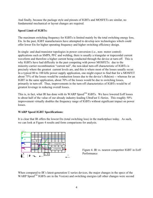
It is clear that IR offers the lowest Ets (total switching loss) in the marketplace today. As such,<br />
we can look at Figure 4 results and form comparisons for analysis.<br />
11-Apr-97<br />
19 14 57<br />
.1 s<br />
100 V<br />
.1 s<br />
5.0 V<br />
.1 s<br />
100 V<br />
Vce, IR<br />
Vce, competitor<br />
.1 s<br />
5.0 V<br />
.1 s<br />
disable<br />
1 V<br />
.5 V<br />
disable<br />
d<br />
DC<br />
DC<br />
d<br />
Ic, IR<br />
Ic, competitor<br />
Competitor<br />
1 GS/s<br />
Figure 4. IR vs. nearest competitor IGBT in Eoff<br />
Performance<br />
DC 8.6 V<br />
NORMAL<br />
When compared to IR’s latest-generation U-series devices, the major changes in the specs of the<br />
<strong>WARP</strong> <strong>Speed</strong> TM <strong>IGBTs</strong> are in the Vce(on) and switching energies (all other changes were second<br />
4


