IRSE News 150 Nov 09.pdf
IRSE News 150 Nov 09.pdf
IRSE News 150 Nov 09.pdf

Create successful ePaper yourself
Turn your PDF publications into a flip-book with our unique Google optimized e-Paper software.
A CASE STUDY IN SAFETY<br />
When the Train A passes 3 Signal, 3 Signal is automatically<br />
placed at STOP. When the rear Train A passes the overlap limit<br />
for 3 Signal, 4 Signal is automatically commanded to display a<br />
PROCEED aspect, but only does so if it is safe i.e. there is no<br />
train detained at 4 Signal with the level crossing open.<br />
SYSTEM ARCHITECTURE<br />
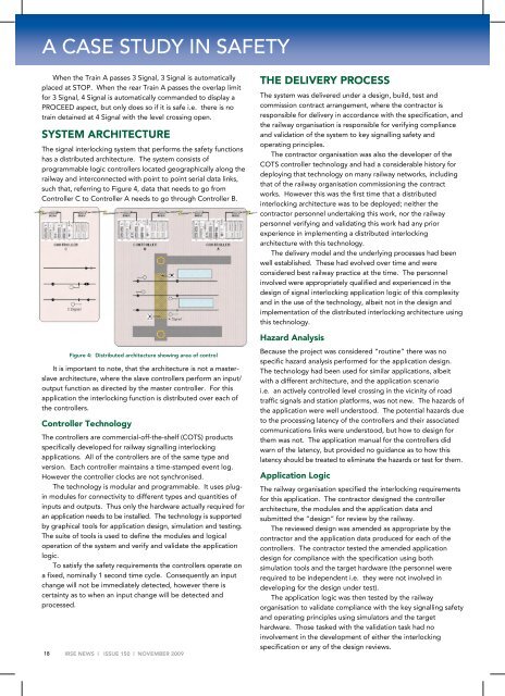
The signal interlocking system that performs the safety functions<br />
has a distributed architecture. The system consists of<br />
programmable logic controllers located geographically along the<br />
railway and interconnected with point to point serial data links,<br />
such that, referring to Figure 4, data that needs to go from<br />
Controller C to Controller A needs to go through Controller B.<br />
18<br />
Figure 4: Distributed architecture showing area of control<br />
It is important to note, that the architecture is not a masterslave<br />
architecture, where the slave controllers perform an input/<br />
output function as directed by the master controller. For this<br />
application the interlocking function is distributed over each of<br />
the controllers.<br />
Controller Technology<br />
The controllers are commercial-off-the-shelf (COTS) products<br />
specifically developed for railway signalling interlocking<br />
applications. All of the controllers are of the same type and<br />
version. Each controller maintains a time-stamped event log.<br />
However the controller clocks are not synchronised.<br />
The technology is modular and programmable. It uses plugin<br />
modules for connectivity to different types and quantities of<br />
inputs and outputs. Thus only the hardware actually required for<br />
an application needs to be installed. The technology is supported<br />
by graphical tools for application design, simulation and testing.<br />
The suite of tools is used to define the modules and logical<br />
operation of the system and verify and validate the application<br />
logic.<br />
To satisfy the safety requirements the controllers operate on<br />
a fixed, nominally 1 second time cycle. Consequently an input<br />
change will not be immediately detected, however there is<br />
certainty as to when an input change will be detected and<br />
processed.<br />
<strong>IRSE</strong> NEWS | ISSUE <strong>150</strong> | NOVEMBER 2009<br />
THE DELIVERY PROCESS<br />
The system was delivered under a design, build, test and<br />
commission contract arrangement, where the contractor is<br />
responsible for delivery in accordance with the specification, and<br />
the railway organisation is responsible for verifying compliance<br />
and validation of the system to key signalling safety and<br />
operating principles.<br />
The contractor organisation was also the developer of the<br />
COTS controller technology and had a considerable history for<br />
deploying that technology on many railway networks, including<br />
that of the railway organisation commissioning the contract<br />
works. However this was the first time that a distributed<br />
interlocking architecture was to be deployed; neither the<br />
contractor personnel undertaking this work, nor the railway<br />
personnel verifying and validating this work had any prior<br />
experience in implementing a distributed interlocking<br />
architecture with this technology.<br />
The delivery model and the underlying processes had been<br />
well established. These had evolved over time and were<br />
considered best railway practice at the time. The personnel<br />
involved were appropriately qualified and experienced in the<br />
design of signal interlocking application logic of this complexity<br />
and in the use of the technology, albeit not in the design and<br />
implementation of the distributed interlocking architecture using<br />
this technology.<br />
Hazard Analysis<br />
Because the project was considered “routine” there was no<br />
specific hazard analysis performed for the application design.<br />
The technology had been used for similar applications, albeit<br />
with a different architecture, and the application scenario<br />
i.e. an actively controlled level crossing in the vicinity of road<br />
traffic signals and station platforms, was not new. The hazards of<br />
the application were well understood. The potential hazards due<br />
to the processing latency of the controllers and their associated<br />
communications links were understood, but how to design for<br />
them was not. The application manual for the controllers did<br />
warn of the latency, but provided no guidance as to how this<br />
latency should be treated to eliminate the hazards or test for them.<br />
Application Logic<br />
The railway organisation specified the interlocking requirements<br />
for this application. The contractor designed the controller<br />
architecture, the modules and the application data and<br />
submitted the “design” for review by the railway.<br />
The reviewed design was amended as appropriate by the<br />
contractor and the application data produced for each of the<br />
controllers. The contractor tested the amended application<br />
design for compliance with the specification using both<br />
simulation tools and the target hardware (the personnel were<br />
required to be independent i.e. they were not involved in<br />
developing for the design under test).<br />
The application logic was then tested by the railway<br />
organisation to validate compliance with the key signalling safety<br />
and operating principles using simulators and the target<br />
hardware. Those tasked with the validation task had no<br />
involvement in the development of either the interlocking<br />
specification or any of the design reviews.