IRSE News 150 Nov 09.pdf
IRSE News 150 Nov 09.pdf
IRSE News 150 Nov 09.pdf

Create successful ePaper yourself
Turn your PDF publications into a flip-book with our unique Google optimized e-Paper software.
<strong>IRSE</strong> NEWS<br />
ISSUE <strong>150</strong> NOVEMBER 2009
RAILWAY SIGNALLING CAREERS, SYDNEY AUSTRALIA<br />
United Group Infrastructure specialises in the delivery<br />
of turnkey rail systems solutions, and has developed<br />
unrivalled technical expertise in key rail systems; signalling,<br />
communications, traction power, overhead electrification<br />
and specialist track infrastructure.<br />
The Signalling Solutions division is one of the largest private<br />
sector suppliers of design construction and maintenance<br />
capability in signalling and railway network systems in<br />
Australia and New Zealand; offering our clients a wide<br />
range of services from design and construction to complete<br />
signalling, communication and train control systems for<br />
heavy haul, passenger and light rail projects.<br />
UGL Careers is seeking expressions of interest for upcoming<br />
projects in our Sydney operation:<br />
Y Signal Design Engineer Y Project Engineer<br />
Y Senior Signal Design Engineer Y Project Manager<br />
Y Design Manager<br />
To send your resume please visit:<br />
http://www.uglcareers.com/opportunities.php<br />
click UGL Infrastructure, and enter job code 440 or for<br />
more information please call Fiona Weir on<br />
+61 7 3833 1904.<br />
SIGNALLING INSTALLATION & MAINTENANCE SERVICES LTD<br />
SIMS is a Link-up and ISO 9001 accredited Equal Opportunities<br />
company that provides a wide range of consultancy and resourcing<br />
services to the railway signalling industry, from project conception,<br />
through detailed design and installation to testing & commissioning.<br />
We are presently looking to expand our in-house capability to help<br />
deliver our current and future workload.<br />
We therefore have immediate opportunities for self-motivated<br />
individuals holding <strong>IRSE</strong> Licences in the following categories:<br />
• Signalling Designer<br />
• Signalling Principles Designer<br />
• Signalling Design Verifier<br />
• Signalling Functional Tester<br />
• Signalling Principles Tester<br />
• Signalling Tester in Charge<br />
We are particularly interested in hearing from individuals who<br />
hold Signalling Principles Designer and Signalling Design Verifier<br />
Licences. Experience of preparing and verifying designs for<br />
conventional London Underground signalling systems would be an<br />
advantage, but we can offer the necessary instruction and mentoring<br />
to achieve the required level of competence where necessary.<br />
We offer competitive rates on a contract basis and the benefit of<br />
working in a professional yet friendly environment based near<br />
Fenchurch Street in the City of London.<br />
Closing date for applications is 30 th <strong>Nov</strong>ember 2009.<br />
To apply for any of the positions listed above please send your CV<br />
via email to: inbox@sims-uk.com<br />
www.simsrail.co.uk<br />
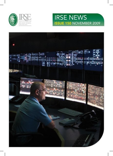
Front Cover: A view of the operating floor inside the signalling control centre at Rugby, overseeing part of the West Coast Main Line in the UK.<br />
Photo: Network Rail
NEWS VIEW <strong>150</strong><br />
A Global Role<br />
<strong>IRSE</strong> NEWS is published monthly by the Institution of<br />
Railway Signal Engineers (<strong>IRSE</strong>). The <strong>IRSE</strong> is not as a<br />
body responsible for the opinions expressed in<br />
<strong>IRSE</strong> NEWS.<br />
© Copyright 2009, <strong>IRSE</strong>. All rights reserved.<br />
No part of this publication may be reproduced,<br />
stored in a retrieval system, or transmitted in any<br />
form or by any means without the permission in<br />
writing of the publisher. Copying of articles is not<br />
permitted except for personal and internal use.<br />
Multiple copying of the content of this publication<br />
without permission is always illegal.<br />
Editor<br />
Ian J Allison<br />
31 Bainbridge Road, Loughborough, LE11 2LE, UK<br />
Tel: +44 (0) 7794 879286<br />
e-mail: irsenews@btinternet.com<br />
Deputy Editor<br />
Tony Rowbotham<br />
36 Burston Drive, Park Street, St Albans, AL2 2HP, UK<br />
e-mail: irsenews@aol.com<br />
Assistant Editors<br />
(Overseas)<br />
Tony Howker e-mail: ahowker@bigpond.com<br />
(Younger Members)<br />
Nigel Handley e-mail: nigel.handley@Irrail.com<br />
Contributions<br />
Articles of a newsworthy or technical nature are always<br />
welcome for <strong>IRSE</strong> NEWS. Members should forward<br />
their contributions to one of the Editors listed above.<br />
Advertising<br />
For advertising rates and deadlines call<br />
Christopher Bean at Ten Alps Publishing<br />
Tel: +44 (0)20 7878 2415<br />
Fax: +44 (0)20 7379 7118<br />
e-mail: Chris.Bean@tenalpspublishing.com<br />
Advertisements are accepted on the basis that the<br />
advertiser and agency (if any) warrant that the<br />
advertisement contents are true and correct in all<br />
respects.<br />
Web Site<br />
For up to date information about the Institution or its<br />
activities, or to download a membership application<br />
form, log on to the <strong>IRSE</strong> Web Site: www.irse.org<br />
Production<br />
<strong>IRSE</strong>: Stuart Angill, Production Manager<br />
Printing and Mailing: Fericon, Reading<br />
London Office<br />
<strong>IRSE</strong>, 4 th Floor, 1 Birdcage Walk, Westminster,<br />
London, SW1H 9JJ, United Kingdom<br />
Enquiries<br />
MEMBERSHIP OR OF A GENERAL NATURE<br />
Tel: +44 (0)20 7808 1180<br />
Fax: +44 (0)20 7808 1196<br />
e-mail: hq@irse.org<br />
PROFESSIONAL DEVELOPMENT<br />
Tel: +44 (0)20 7808 1186<br />
e-mail: training@irse.org<br />
LICENSING<br />
Tel: +44 (0)20 7808 1190<br />
e-mail: licensing@irse.org<br />
Another milestone achieved in the history of <strong>IRSE</strong> NEWS. This is a good moment for<br />
some reflection. A couple of questions are appropriate in order to test the magazine.<br />
Is the magazine productive? After a slower start (22 years for the first 100) the<br />
speed of publications is now gathering pace, with only five years needed for the next<br />
50. That means that from just over 2.5 months between issues, the waiting time for<br />
the anxious reader has now been reduced to less than half. Eleven Issues per year<br />
with several hundred pages in total is the current status. That is a good sign when it<br />
comes to measuring productivity.<br />
Then what about the content? Also here we see a change in both topic and depth.<br />
We cannot say it was a straight track over the last five years (and sometimes it was a<br />
bit bumpy seeing the heated discussions on some topics) but I hope you agree with<br />
me in stating that the current content matches the expectations of many members.<br />
Is the magazine attractive? I think it is. From a somewhat dull image in line with<br />
our role as keepers of the safety of the railway we now have a magazine that does<br />
invite reading. The new layout is a good step forward. It is in line with many<br />
magazines with a much bigger print number and where teams of multiple professional<br />
members dedicate themselves to the mock-up and layout of the articles.<br />
Is this good enough? No, I do not think so, but not because of the magazine and<br />
the dedication of the team that makes it happen, together with the happy volunteers<br />
who submit the articles. It is the because of the role of the <strong>IRSE</strong> which is becoming<br />
more and more global. That change will force the magazine into a new direction. The<br />
magazine needs to show more about the world wide activities of the Institution so that<br />
the members get information about technology, processes and, above all, events that<br />
are relevant to them in their geographical context. That is the challenge. Good luck<br />
in the future.<br />
Frans Heijnen, <strong>IRSE</strong> President<br />
IN THIS ISSUE<br />
Signalling: Have we lost the plot? (London <strong>Nov</strong>ember Paper) 2<br />
Page<br />
Eddie Goddard<br />
Semi-automatic, driverless, and unattended operation of trains 8<br />
<strong>IRSE</strong> International Technical Committee<br />
Australian Competency Management Systems – Signalling Design 11<br />
Martha Gordillo<br />
Complexity and Safety: A Case Study 16<br />
George Nikandros<br />
Interesting Infrastructure: Lincoln Co-acting Signals 21<br />
J D Francis<br />
Industry <strong>News</strong> 22<br />
Book Review: Compendium on ERTMS 25<br />
David Slater<br />
Axle Counter & Technology Seminar 26<br />
Walter Peckruhn<br />
Narrow gauge points - An economical approach 29<br />
Stuart Marsh<br />
<strong>IRSE</strong> Matters Correction to Printed Programme Card 32<br />
<strong>News</strong> from New Zealand 32<br />
Younger Members 33<br />
Minor Railways Section 34<br />
Midland & North Western Section 37<br />
Signalling Pioneers: C B Byles Ken Burrage 38<br />
Feedback 40<br />
Membership Matters<br />
outside back cover<br />
il<br />
<strong>IRSE</strong> NEWS | ISSUE <strong>150</strong> | NOVEMBER 2009<br />
1
NOVEMBER PAPER<br />
Signalling: Have we lost the plot?<br />
By Eddie Goddard<br />
Paper to be read in London on 11 <strong>Nov</strong>ember 2009<br />
The author is a past President of the <strong>IRSE</strong><br />
INTRODUCTION<br />
This paper has two themes. The first concerns the need to<br />
ensure the continuity of signal engineers able to see the big<br />
picture. The second looks at the way that signalling is provided<br />
and, in particular, the role of assurance in the signalling process.<br />
It endeavours to show that there are linkages between the<br />
two and that the industry has to face up to the changes that<br />
have taken place. Finally it proposes a way forward to enable<br />
the signalling industry to remain economic and efficient.<br />
It relies heavily on the author’s experience and so is written<br />
from the point of view of UK Metro signalling in the United<br />
Kingdom. It should not be seen as relating to any particular<br />
organisation. However it attempts to bring in the experience of<br />
national railways and of other countries.<br />
SCENE SETTING<br />
Is perception reality? The following are views currently held by<br />
many outside the signalling industry and often expressed by<br />
those within it (see Ref. 1).<br />
They don’t make them like they used to.<br />
“When the current breed of signal engineers retire there will<br />
be no one left that understands the whole picture. All that we<br />
have now are specialists.”<br />
The weight of evidence.<br />
“The amount of documentation for a project generated to<br />
satisfy the assurer(s) outweighs that used to develop the project<br />
itself. The critical path now lies through the assurance chain.<br />
As a result project cost and implementation time are becoming<br />
untenable.”<br />
Why do these things matter? If they are true, then the cost<br />
of introducing new systems will become unbearable, signalling<br />
unaffordable and delays unacceptable. If we do not do<br />
something we will be left behind. Railways themselves will<br />
become uneconomic and will fall into decline. The benefits that<br />
they can bring will be lost, and we will all be out of a job. Even<br />
if they are not true the perception is still there, and unless we<br />
are able to counter it the signalling industry will be marginalised<br />
and investments made elsewhere (see Ref. 2). What is more<br />
likely is that new companies will be formed which are more<br />
willing to adopt new ways and able to undercut the traditional<br />
suppliers through adopting a radical approach.<br />
THEY DON’T MAKE THEM LIKE THEY<br />
USED TO<br />
Career Development<br />
To develop these themes the paper will consider the career of a<br />
typical signal engineer of an earlier generation—as experienced<br />
by the author at the time.<br />
Training<br />
A total apprenticeship of six years, starting as a Dip Tech Trainee.<br />
Academic<br />
Practical<br />
Signalling<br />
theory<br />
Management<br />
theory<br />
Railways<br />
Project<br />
Testing<br />
English, Maths and Physics at school.<br />
Sponsored for a Degree in Electrical and<br />
Telecommunications Engineering, and a<br />
Master’s Degree in Systems Engineering.<br />
Time spent in workshops, with the Maintainer<br />
on call and with an installation gang.<br />
Knowledge gained of practicalities, as well as<br />
the cultures of the different disciplines.<br />
Power Signal Linesman course and Drawing<br />
Office course.<br />
British Rail junior management course.<br />
Time spent with Divisional Inspector on<br />
stations and with drivers, looking into incidents<br />
and observing his staff management.<br />
Absorbing front-line operator’s culture.<br />
Time spent in control rooms and generally out<br />
and about on the railway.<br />
Produced a railway simulator for the Victoria<br />
Line through extensive work with rolling stock<br />
engineers to understand train characteristics.<br />
New communications system on live rails in an<br />
automatic train area. On the track, no lookouts,<br />
no briefing, no personnel protection equipment.<br />
Doing<br />
Design<br />
Producing “red inks” by copying the work of the Engineering<br />
Assistant (just two years older than myself!), then preparing<br />
circuits and having them checked. Being given feedback on the<br />
design and hence learning the best way. Seeing the approver<br />
work with the Engineering Assistant and his experience being<br />
fed back. Later still, seeing the two principal designers in active<br />
debate about the more esoteric aspects of the design.<br />
Installation<br />
Held the meter for the Principal Installation assistant (Tester in<br />
charge). Observed the final commissioning process where the<br />
tester, without reference to the circuits but used the scale plan<br />
and working from first principles ensured that the site<br />
performed as it should by using track dropping boards and lots<br />
of staff. Saw design anomalies picked up and circuit changes<br />
made through the designer sitting alongside the tester. Later,<br />
put in charge of testing a signal! Realising the homework that<br />
went into the testing process with study of circuits, and<br />
discussion of the designs before testing took place.<br />
2<br />
<strong>IRSE</strong> NEWS | ISSUE <strong>150</strong> | NOVEMBER 2009
Development<br />
Put in charge of making a new<br />
communications system work. Working<br />
directly with supplier’s team and devising<br />
modifications. Jointly installing and<br />
testing them.<br />
Railway<br />
Working with Rolling Stock Engineers,<br />
spending considerable time with Line<br />
Controllers and Train Regulators and<br />
riding in train cabs.<br />
Management<br />
Working in a multidisciplinary team with a<br />
senior operator, timetable compiler, Data<br />
Processing expert, on specification of a<br />
computer based railway control system. 3<br />
Consultancy<br />
Providing independent assurance to<br />
signalling contractors for novel signalling<br />
systems through London Transport’s<br />
external consultancy arm. As a result<br />
exposed to other countries’ signalling<br />
cultures, and to commercial pressures.<br />
Managing<br />
Development<br />
Leading the team introducing computer<br />
control systems for the Underground.<br />
Providing the engineering support to the<br />
cross-directorate team (engineering,<br />
operations, revenue collection, supplier)<br />
developing the Underground’s automatic<br />
fare collection and selling systems<br />
(became Oyster) with the supplier.<br />
Maintenance<br />
Responsible for the signalling<br />
maintenance division.<br />
Client<br />
Managing the Signalling client<br />
organisation.<br />
Systems<br />
Managing the Rolling Stock and Signalling<br />
client organisations, and forming the<br />
Systems Engineering team.<br />
International committees<br />
Working on standards-setting committees<br />
for RIA, ORE, and the <strong>IRSE</strong> technical<br />
committee. Gaining wider appreciation of<br />
different signalling and operating<br />
companies, different cultures, and<br />
different commercial arrangements.<br />
Professional career<br />
Supported throughout career on <strong>IRSE</strong><br />
activities, attending lectures and<br />
conventions as a student, granted time to<br />
attend council meetings, through to<br />
support during presidential year.<br />
Assuring<br />
Chief Engineer<br />
Managing the team that produces<br />
standards and enforces compliance for all<br />
engineering disciplines.<br />
Chairman of safety review panels<br />
Approving introduction of new technology<br />
and systems.<br />
Career Development<br />
Underlying all the above was the certain<br />
knowledge that a full career could be<br />
followed through one employer; that the<br />
training manager had mapped out the<br />
early stages and provided mentoring<br />
through those difficult times; and that the<br />
senior managers had devised career<br />
progression plans, and that one’s promotion<br />
was often subject to those plans. Sideways<br />
and even downward moves were<br />
encouraged, with the promise that “rescue<br />
would be at hand” should the move prove<br />
to be too disastrous.<br />
The Signalling World<br />
Railways<br />
Railways were largely self-contained. They<br />
did everything themselves. (London<br />
Underground even had its own power<br />
generating stations).<br />
They were staffed to a great extent by<br />
former soldiers and mariners, and<br />
organised as operations, engineering<br />
disciplines, and support. Each engineering<br />
discipline was led by a Chief Engineer<br />
accountable for development, design,<br />
installation and maintenance. The Chief<br />
made decisions, right or wrong, and was<br />
accountable for them. He knew all aspects<br />
and was capable of, and indeed far too<br />
frequently did, issue detailed designs<br />
himself (Robert Dell when Chief Signal<br />
Engineer would issue his circuits in green<br />
ink so that everyone knew not to question<br />
them!)<br />
Suppliers<br />
Suppliers built what they were asked to<br />
build. Research and development were<br />
carried out jointly under profit sharing<br />
agreements, with engineering decisions<br />
being made first and commercial<br />
consequences agreed later. Engineers<br />
worked together as a team, each having<br />
his own role. When things went wrong,<br />
they fixed them. The result was often gold<br />
-plated signalling - thank goodness,<br />
because most of it is still in commission,<br />
and working well beyond its expected life<br />
of forty years.<br />
Safety<br />
Safety was embodied in the fail-safe<br />
concept. Every effort was made to<br />
understand the failure modes of<br />
components and eliminate the causes of<br />
wrong side failures (see Ref. 4). As a<br />
result interface problems were greatly<br />
simplified, in that each component in the<br />
chain took on trust that the preceding<br />
ones would fail safe and so did not have<br />
to consider any complex interactions.<br />
Reliability was seen as subservient to<br />
safety.<br />
On London Underground a clear<br />
distinction was made between safety and<br />
non-safety circuits, so that the safety<br />
circuitry was kept as simple as possible<br />
(see Ref. 5).<br />
Personnel safety was largely based on<br />
drumming into people just how dangerous<br />
the railway was, and then expecting them<br />
to look after themselves. As a result<br />
working on the railway was seen as the<br />
second most dangerous occupation, after<br />
the mining industry.<br />
Assurance<br />
Although the word “assurance” would not<br />
have been recognized in this context then,<br />
the pursuit of ever-increasing levels of<br />
safety was ingrained in all signal<br />
engineers, and closely linked to the<br />
hierarchical chain. Engineering managers<br />
were technically competent in the main,<br />
and had risen through the ranks. They<br />
were fully empowered to manage, they<br />
made decisions and they managed the<br />
budgets. They were accountable for<br />
delivery to cost and to time, and for the<br />
quality of the end result.<br />
Designs were “Checked” and<br />
“Approved” by the design engineer’s<br />
manager as part of the normal production<br />
process. They would sign off the designs<br />
only when satisfied that they were correct.<br />
Schemes were approved by the Design<br />
Engineer. Independent checking was<br />
carried out between drawing offices and<br />
through discussion with the installers and<br />
testers.<br />
Components were tested in the<br />
supplier’s factory and signed off by<br />
competent inspectors, 100% checking<br />
being the norm. Critical components<br />
were retested by the railway.<br />
Installers’ work was checked by wire<br />
counts and testing initially, to prove that<br />
<strong>IRSE</strong> NEWS | ISSUE <strong>150</strong> | NOVEMBER 2009 3
NOVEMBER PAPER<br />
the circuits worked as designed<br />
(verification). Then it was checked by a<br />
senior tester to ensure that it met all the<br />
signalling principles and enabled the<br />
operator to run the intended service<br />
safely (validation). At each stage a simple<br />
signature sufficed.<br />
Close attention was paid to every<br />
failure and the root cause was sought, be<br />
it equipment, procedural or human error.<br />
Her Majesty’s Railway Inspectorate<br />
– the Regulator<br />
HMRI staff were traditionally ex-military.<br />
They saw their role as that of an enforcer,<br />
but they always had the clear motivation<br />
to improve the railway and its safety and<br />
to protect the workforce. They looked to<br />
ensure that there was adequate<br />
paperwork, but spent most of their time<br />
talking to the people - operators,<br />
engineers and managers alike. They<br />
sought evidence principally through<br />
testing the calibre of the people they<br />
talked to.<br />
They gave approvals following a<br />
staged interrogation. “Cooksey’s Court”<br />
was always something that had to be<br />
prepared for, and it nearly always<br />
surprised with the perception of the<br />
questions asked (see Ref.6).<br />
They were able to turn a blind eye on<br />
occasions but let the managers know they<br />
had done so.<br />
They conducted enquiries with the aim<br />
of finding out why the accident had<br />
happened and preventing it happening<br />
again.<br />
FROM THEN TO NOW<br />
Education<br />
Engineering as a profession fell out of<br />
fashion, and universities have struggled to<br />
recruit good school leavers. In a survey in<br />
1997 only 60% of schoolchildren over 16<br />
had even heard of engineering as a<br />
career, less than 3% were interested in<br />
railways (see Ref. 7). Sponsorship for<br />
engineering courses and apprenticeships<br />
became scarce. The few graduates that<br />
emerged were attracted to lucrative<br />
careers in finance. As a result the flow of<br />
young engineers all but dried up. Poor<br />
publicity about railways made it hard to<br />
recruit from even this depleted pool of<br />
talent.<br />
Railways<br />
The old monoliths have been broken up.<br />
On national railways, operation has been<br />
franchised to train operating companies,<br />
rolling stock is provided by rolling stock<br />
companies, signalling and permanent way<br />
by infrastructure companies.<br />
Even in Metros the maintenance has<br />
often been franchised out, and new<br />
signalling and rolling stock provided by<br />
outside suppliers.<br />
Suppliers<br />
Suppliers have formed into large<br />
international consortia. They have been<br />
required to take on many of the roles<br />
previously performed by the railway<br />
companies.<br />
At the same time they have continued<br />
to concentrate on manufacture, with<br />
application design, installation,<br />
commissioning, maintenance and<br />
assurance often being franchised out to<br />
smaller, niche companies.<br />
Safety<br />
Safety has become an industry in itself.<br />
Companies have been formed or<br />
consultancies have taken on the role of<br />
assurer. In part this is through the<br />
requirements for independent safety<br />
assurance to satisfy the requirements of<br />
EN6<strong>150</strong>8 and for Notified Bodies to<br />
satisfy the European Commission’s need<br />
to demonstrate fair competition.<br />
It is also however a reflection of how<br />
difficult it is to meet the expectations of<br />
the safety industry itself - that is, to<br />
prepare safety cases, proofs of safety,<br />
safety plans etc. in order to demonstrate<br />
that the requirements arising from the<br />
criterion, “As Low As Reasonably<br />
Practicable” have been met.<br />
Software and communications-based<br />
systems are more difficult to understand<br />
than the old signalling circuits. It is harder<br />
to see the whole picture The<br />
introduction of project managers separate<br />
from engineers results in a tendency for<br />
the engineers to concentrate on quality<br />
and leave the need to meet timescales<br />
and budgets to the project manager, and<br />
vice versa. As a result decisions are often<br />
made in practice by the person with the<br />
most power rather than the one with the<br />
best knowledge.<br />
Regulation<br />
Perhaps the biggest change was the need<br />
for regulators to reflect the change that<br />
had taken place in public perception. It is<br />
no longer the case that “accidents<br />
happen.” It is necessary to show that<br />
someone is to blame. As a result court<br />
cases follow any accident, and evidence is<br />
required to demonstrate that correct<br />
procedures have been followed.<br />
Engineering judgement alone is no longer<br />
acceptable as an explanation for<br />
decisions. Even regulators find their<br />
decisions questioned and action<br />
threatened against them.<br />
As a result the whole industry has<br />
become highly defensive. It is no longer<br />
wise to be a single decision maker.<br />
Regulators see their role as being<br />
protectors of the public first, improvers of<br />
the railway second.<br />
More recently in the UK the ROGS<br />
regulations (see Ref. 8) have placed<br />
greater emphasis on the safety<br />
management system and the need to<br />
demonstrate adherence to it, and have<br />
recognised the need for collaboration<br />
between parties. Written verification<br />
plans identify the roles of the parties and<br />
where review is required, the level of<br />
intrusion required being risk-based.<br />
THE WEIGHT OF<br />
EVIDENCE<br />
The net result of the move from simple,<br />
fail-safe components to the need to prove<br />
a system to be safe, with the use of<br />
software in vital systems, combined with<br />
the demand for documented evidence of<br />
every stage of the process in order to<br />
satisfy a potential court of law has resulted<br />
in an industry that has definitely “lost the<br />
plot.”<br />
The basic elements of design,<br />
checking and approval are still<br />
recognisable throughout the supply chain,<br />
but part of their purpose has been lost.<br />
The essential learning feedback from<br />
master to pupil has been replaced by<br />
assurance. There is often a culture in<br />
which the assurer feels obliged to find<br />
fault. At its most extreme it manifests<br />
itself in the form “This is wrong but I will<br />
not tell you why it is wrong” - an approach<br />
based upon the mistaken belief that it will<br />
cause the submitter to find all the other<br />
examples of error.<br />
4<br />
<strong>IRSE</strong> NEWS | ISSUE <strong>150</strong> | NOVEMBER 2009
In many cases the errors found are due<br />
to carelessness. Too often though they<br />
stem from the submitter’s lack of local,<br />
domain knowledge. In other cases they<br />
stem from a lack of specialist knowledge<br />
of the product or interfaces. In some<br />
cases “errors” are the result of<br />
straightforward opinion engineering on<br />
the part of the assurer.<br />
In extreme cases, specialist assurance<br />
writers are employed who have no<br />
knowledge of the product and simply<br />
reprocess paperwork without checking<br />
with the originators.<br />
Despite this demand for a structured<br />
approach, capturing requirements fully<br />
and determining the test criteria at the<br />
commencement of a project remain<br />
beyond us. Hence a lot of the documentation,<br />
when submitted, reflects the<br />
changes that have had to be made along<br />
the way. As a result, even in well-run<br />
projects, documentation tends to lag<br />
behind production. Frequently this results<br />
in a need to employ specialists to produce<br />
safety plans, safety cases, proofs of safety<br />
etc. All too often these specialists are from<br />
another company, and nearly always they<br />
are not the people doing the actual work.<br />
This in turn leads to another tranche of<br />
documentation as the doers, testers,<br />
commissioning agents, operators and<br />
maintainers finally catch up with the<br />
process and request permission to<br />
operate. All too often this is at the point<br />
of maximum pressure on the project to<br />
meet deadlines, when relationships<br />
between the companies are at their most<br />
strained. As a result, assurance becomes<br />
the scapegoat for late delivery.<br />
WHAT HAS TO BE DONE<br />
Career Development<br />
Education<br />
The first stage is to tackle the lack of<br />
schoolchildren taking maths and science.<br />
At least this has now been recognised and<br />
Mathematics education is improving. We<br />
all need to spread the word.<br />
In the United Kingdom the “Science,<br />
Technology, Engineering and Maths<br />
Ambassador” or “STEM Ambassador”<br />
programme is helping to address this.<br />
The next need is to encourage<br />
schoolchildren to opt for engineering. For<br />
Transport for London, Project Brunel<br />
supported by the Royal Academy is<br />
tackling this, and it needs our support.<br />
Most importantly all sectors of the<br />
industry need to address the issue and<br />
reinstate apprenticeships, graduate<br />
training etc. Universities need to be<br />
encouraged to provide degree and<br />
postgraduate courses to meet this need.<br />
In this regard the UK is certainly lagging<br />
behind the rest of Europe as well as China<br />
and India, where technical universities have<br />
greater status and where Railways, and even<br />
Railway Signalling specifically, are seen as<br />
suitable subjects for first degree courses.<br />
Training<br />
There is a belief that market forces will<br />
magically provide the incentive needed<br />
for young engineers to plot their careers<br />
and, by suitable movements between<br />
companies, obtain the breadth of training<br />
required to take on senior positions. In a<br />
few cases this has indeed worked, but the<br />
fact that this paper has been called for<br />
demonstrates that overall it has failed to<br />
produce the numbers required.<br />
The greatest need is to provide a<br />
career path that enables suitable young<br />
engineers to gain the breadth of<br />
understanding necessary to become a<br />
fully-fledged signal engineer and manager<br />
of signalling. The move back to<br />
integrated infrastructure companies<br />
places an onus on these companies to<br />
reinvigorate their training approach.<br />
Similarly the major signalling suppliers<br />
need to recognise the need to invest in<br />
the future, looking to move suitable<br />
candidates around the divisions so that<br />
they can gain experience in marketing,<br />
development, installation and, where<br />
possible, maintenance.<br />
Finally all companies should provide<br />
opportunities for young school leavers by<br />
providing graduate training courses, and<br />
the universities should be encouraged to<br />
provide modular training that will enable<br />
students to pick and mix and still acquire<br />
the degrees that they need to satisfy the<br />
Institutions.<br />
The biggest gap remains the lack of<br />
opportunity to gain experience of railway<br />
operation. There is clearly a need to<br />
provide training opportunities and to give<br />
suitable candidates a chance to take on<br />
roles closer to the operation of the<br />
railway. For Metros this is still possible, as<br />
signalling and train operation are normally<br />
in the same company. As an example,<br />
recent London Underground signalling<br />
trainees have qualified as train drivers.<br />
For the national railways the split between<br />
train operating companies and<br />
infrastructure managers makes it much<br />
more difficult. Surely a protocol could be<br />
drawn up so that all share the burden?<br />
Suppliers’ engineers need to be given<br />
access to the railway so that they can<br />
place their promising engineers in posts<br />
that will give them the experience they<br />
need. As the infrastructure managers<br />
need to ensure that their own engineers<br />
gain experience of the problems of<br />
production and of research and<br />
development, some form of mutual<br />
cooperation seems once again to be<br />
desirable. Again the simplest approach<br />
would appear to be a protocol that<br />
enables staff to be swapped between<br />
companies.<br />
Consultancies provide the ideal<br />
training ground in many ways, spanning all<br />
areas of signalling and all countries. It is<br />
vital that they contribute to the<br />
development of engineers from the start<br />
and support the efforts of industry and the<br />
railways. There is a tendency for the<br />
mature engineers to end their careers in<br />
consultancy and thus the mentoring of the<br />
younger engineers is lost - or even made<br />
the subject of contracts!<br />
The final, and probably the greatest,<br />
concern is the need to address the<br />
specialist companies. There is a need to<br />
find software engineers with the requisite<br />
knowledge of the railway, and safety<br />
specialists who understand the reality of<br />
railway engineering. Many subcontractors<br />
providing installation and<br />
maintenance staff, companies specialising<br />
in providing test and commissioning<br />
engineers - are too small to sustain a<br />
training course themselves and in any case<br />
too specialised to be able to provide the<br />
opportunities needed in-house.<br />
Today’s signalling manager must be<br />
able to work with many disciplines, to<br />
work in a complex commercial<br />
environment and to integrate diverse<br />
teams from different companies.<br />
Technical skills are less important than<br />
managerial and team-building skills. The<br />
abilities to get the best from people and<br />
to ask the right questions at the right time<br />
are essential. Good judgement remains<br />
the greatest requirement, and it needs the<br />
<strong>IRSE</strong> NEWS | ISSUE <strong>150</strong> | NOVEMBER 2009 5
NOVEMBER PAPER<br />
manager to have a broad background, but<br />
that can be gained in different ways. It is<br />
no longer necessary to have done everything,<br />
indeed it is no longer possible.<br />
Equally there is a need for specialists,<br />
able to concentrate on one area of the<br />
industry, but these too must be given the<br />
opportunity to broaden their knowledge<br />
and learn the basics of signalling and<br />
railway operation.<br />
Proposal<br />
A potential solution to all the above is to<br />
take an idea from the environmental lobby<br />
with the Carbon Tax. If all companies were<br />
to recognise the need for signalling<br />
training, and to accept a training levy<br />
offset by the offering of training posts and<br />
suitable publicity produced to show that<br />
this is an integrated scheme, that would<br />
attract people into the profession with the<br />
knowledge that railways, and signalling in<br />
particular, are worth coming into as a<br />
career. That would enable engineers to<br />
select the training they require without<br />
having to chop and change between<br />
companies.<br />
It would give companies an incentive<br />
to establish training schools and courses,<br />
and to support the existing training<br />
companies. Whilst this is a potential<br />
problem it has generally been recognized<br />
and training facilities have been provided<br />
or enhanced to address the shortage of<br />
signalling technicians.<br />
The <strong>IRSE</strong> could provide a framework<br />
to enable this to be organised by the<br />
companies themselves. All that is needed<br />
is a simple pro-forma for placements and<br />
a means of identifying the places<br />
available.<br />
ASSURANCE<br />
The first, and greatest, problem is that no<br />
one company is capable of doing<br />
everything and so the work must be split<br />
amongst a number of companies. No-one<br />
can get their head around the whole<br />
picture. The Chief Engineer of today<br />
would be hard-pressed indeed to know all<br />
the detail of the software,<br />
communications, equipment, testing<br />
procedures and maintenance capability.<br />
The simple philosophy of fail-safe can<br />
no longer be applied, so that the<br />
signalling must be seen as part of a<br />
system and all interfaces must be<br />
considered and defined clearly.<br />
Keep it simple<br />
What the signalling is required to do has<br />
expanded, and capturing those<br />
requirements is a major task in itself. The<br />
clear distinction between what is required<br />
to keep trains safe and all the other<br />
functions that the signalling performs has<br />
become blurred. The fact remains that<br />
trains are subject to the basic laws of<br />
nature and so plausibility tests can easily<br />
be built into the systems.<br />
Greater use should be made of two<br />
basic principles in the approach to<br />
signalling: keep the safety element of the<br />
system as simple as possible; and employ<br />
diversity to reduce dependence on any<br />
one element.<br />
Use industry standards<br />
It is no longer possible to test every path<br />
through the logic, and issues of timing<br />
and interaction need to be considered.<br />
The software industry has however<br />
developed tools to cover every element of<br />
the life-cycle. Signalling needs to<br />
embrace these tools, while avoiding the<br />
temptation to cite every one as mandatory<br />
for SIL 4 systems.<br />
There needs to be a realisation that<br />
safety integrity (SIL) levels were<br />
developed as a shorthand way of putting<br />
software-based systems into a safety<br />
context. Numbers were added to provide<br />
parallels with the standard failure modes,<br />
effects and criticality or FMECA (Failure<br />
Mode, Effects & Criticality Analysis)<br />
approach possible with discrete<br />
components.<br />
A clear plan for the assurance<br />
processes to be adopted and definition of<br />
the level of assurance to be applied at<br />
each stage, and which company/individual<br />
will be responsible at each stage, will<br />
reduce the overlap - checkers checking<br />
checkers - and enable adequate planning<br />
and time to be made available.<br />
Systems approach<br />
Signalling must therefore embrace the<br />
systems engineering approach and work<br />
to clear assurance processes, but the<br />
current divide between assurers and doers<br />
must be bridged nevertheless.<br />
If requirements are properly captured,<br />
acceptance criteria identified at the outset<br />
and changes rigorously controlled then<br />
the classic model for verification and<br />
validation can be followed and the result<br />
is a largely self-assured product.<br />
If assurers throughout the supply chain<br />
are prepared to accept less than perfect<br />
English and Grammar then the need to<br />
spend time rewriting documents can be<br />
eliminated. If parties communicate<br />
throughout, the need for reports and<br />
statements can be greatly reduced.<br />
Modelling<br />
One approach is to make greater use of<br />
modelling as part of the specification<br />
process. It is generally much easier to<br />
define what is wanted if the potential<br />
users are able “to see it and play with it,”<br />
rather than trying to specify it in abstract<br />
terms. Well-constructed models also<br />
provide a basis for the suppliers to work<br />
from, and can even be used to set the<br />
final acceptance criteria.<br />
Greater reliance on simulation for<br />
testing with more emphasis placed on<br />
proving the accuracy of the models<br />
removes some of the need for site testing.<br />
Accurate models also enable suppliers to<br />
test their interfaces with other suppliers in<br />
a controlled environment.<br />
Self documentation<br />
Automated testing tools provide self<br />
documentation; comprehensive logging of<br />
events and interim states enables self<br />
documented testing.<br />
Accurate simulators also enable<br />
operators to gain skills in the new system,<br />
and can be incorporated into the training<br />
documentation and even the safety case.<br />
In short, we need to return to the<br />
principle that assurance arises from<br />
doing the right thing and being able to<br />
evidence it, not from writing reams of<br />
paper.<br />
Data<br />
A great deal of attention is paid to the<br />
safety of the underlying system and to the<br />
processes applied to its production. In<br />
practice the most vulnerable part of the<br />
process lies in capturing and inputting the<br />
data that characterise the system. This is<br />
often delegated to the most junior<br />
members of the team, and is only proven<br />
through testing the installation itself.<br />
Attention needs to be paid to means of<br />
reducing the dependence of the system<br />
on the accuracy of data through diversity,<br />
plausibility, and automated testing.<br />
6<br />
<strong>IRSE</strong> NEWS | ISSUE <strong>150</strong> | NOVEMBER 2009
Domain knowledge<br />
None of the above, however is any<br />
substitute for common sense. It is<br />
essential that somewhere in the chain a<br />
check is made by someone with<br />
knowledge of the particular application.<br />
Ideally the person checking the data<br />
should be knowledgeable. The principles<br />
tester must be able to see the big picture<br />
and know how the system will be used.<br />
Ideally the systems architect will have, or<br />
will have access to, a rounded signal<br />
engineer.<br />
Paperless assurance<br />
By applying the above the reliance on<br />
error-free software and data should be<br />
reduced, systems should be self checking,<br />
verification and validation built into the<br />
production process, and the safety case<br />
built around the production process. In<br />
the end assurance comes from a<br />
knowledge that the system has been<br />
designed in such a way as to enable it to<br />
operate safely, that the right people have<br />
done all that can reasonably be expected<br />
of them and that they have been<br />
supported by the application of sufficient<br />
process controls to trap any errors that<br />
might have crept in.<br />
The emphasis must be on getting it<br />
right first time, feeding back any<br />
shortcomings found and improving the<br />
process at all stages; targeting any<br />
surveillance activity on a risk basis and<br />
applying basic common sense, placing<br />
greater trust on the producers and using<br />
the resources to improve their knowledge<br />
and skills.<br />
Public opinion<br />
Of course, a greater change<br />
could be made if public<br />
opinion were to be made<br />
aware of the heavy cost the<br />
current regime imposes, but<br />
experience shows that whilst<br />
this might be possible in<br />
normal times, the immediate<br />
reaction to an accident, and<br />
the public outcry that follows,<br />
will mean that such<br />
considerations will be ignored<br />
in the endeavour to find out<br />
who is to blame. It remains<br />
the case therefore that<br />
paperwork will be needed to<br />
provide an audit trail.<br />
ENCORE<br />
It has been remarked that rather than<br />
losing the plot the author has not<br />
recognised that he is in the wrong play!<br />
The world moves on, what used to be is<br />
no longer practicable. It is not possible to<br />
reconstruct the past, but the aim of this<br />
paper has been to use the experience of<br />
previous generations to show that there<br />
are alternatives to today’s accepted UK<br />
norm. As yet other countries have<br />
avoided the worst examples but are far<br />
from immune, and much stems from an<br />
interpretation of European directives.<br />
If the Railway of the 1960s was the<br />
prequel, still highly dependent on the<br />
Victorian past, the railway of today is<br />
much safer (see Ref. 9) and the new<br />
processes have enabled it to adopt the<br />
new technology. What of the sequel? We<br />
must move to overcome the issues that<br />
this paper has raised. Most importantly<br />
we must ensure that we have the actors in<br />
place, with the right scripts.<br />
ACKNOWLEDGEMENTS<br />
Many people have contributed to this<br />
paper, both wittingly and unwittingly! The<br />
author would like to thank the President<br />
for the opportunity and David Waboso for<br />
permission to produce this paper, though<br />
it must be emphasised that the opinions<br />
expressed are the author’s alone and<br />
should not be seen as referring to any<br />
particular organisation or company.<br />
REFERENCES<br />
1 President’s Address: A sustainable<br />
profession? Where are we going? <strong>IRSE</strong><br />
NEWS May 2009<br />
2 Towards the one page safety case <strong>IRSE</strong><br />
Technical Committee, <strong>IRSE</strong> NEWS<br />
June 2009<br />
3 Computer controlled signalling and<br />
regulation, Eddie Goddard, <strong>IRSE</strong><br />
Proceedings, December 1974<br />
4 ORE report A118<br />
5 Automatic Junction working and Route<br />
Setting by Programme, Robert Dell,<br />
<strong>IRSE</strong> Proceedings, October 1958<br />
6 Monitoring Railway Safety - Are we<br />
doing it the right way? <strong>IRSE</strong> March<br />
1990<br />
7 Project Brunel Final Report, Franklin<br />
Andrews, December 2008<br />
8 UK legislation, The Railways and Other<br />
Guided Transport Systems (Safety)<br />
Regulations 2006<br />
9 Railway risks, safety values and safety<br />
costs, Andrew W Evans, Imperial<br />
College, London<br />
<strong>IRSE</strong> NEWS | ISSUE <strong>150</strong> | NOVEMBER 2009 7
INTERNATIONAL TECHNICAL COMMITTEE<br />
Semi-automatic, driverless, and unattended operation<br />
of trains<br />
<strong>IRSE</strong> International Technical Committee<br />
SUMMARY<br />
The mission of any metro transportation undertaking is to<br />
provide safe, reliable, efficient, high quality service to its<br />
passengers in a cost effective fashion. To meet this business<br />
need, our metro systems are increasingly being automated.<br />
Any new metro system constructed today would almost<br />
certainly incorporate some level of automation with many<br />
modern metro systems now providing driverless or unattended<br />
train operation. In addition, higher levels of automation are<br />
also being introduced into the older metro systems around the<br />
world in response to demands for increased capacity on the<br />
existing infrastructure, enhanced levels of safety, improved<br />
customer service, and reduced operating costs.<br />
This article examines the benefits of automation, the<br />
various levels of automation that can be deployed, the<br />
maturity of the technology, and the challenges of selecting the<br />
appropriate level of automation for a specific application. The<br />
article focuses on automation of metro systems. Automation<br />
of our intercity main lines, high speed railways, and freight<br />
lines will be addressed in a separate article.<br />
THE BENEFITS OF AUTOMATION<br />
Metros are an expanding business with many existing metros<br />
operating at or near to their capacity limit. Given the often<br />
prohibitively high costs of constructing new metro lines or<br />
extending platform lengths, the benefits of automation are<br />
therefore invariably linked to maximising the operational<br />
performance of the existing or planned transportation infrastructure.<br />
The characteristics of automation that support this<br />
goal include the following:<br />
Automation of the train driving functions can provide for<br />
more regular and predictable run times between stations,<br />
eliminating the variations inherent with manual driving, and<br />
providing for a more uniform ride quality and reduced<br />
wear-and-tear on train propulsion and braking systems;<br />
Driverless/unattended train operation, with automatic<br />
passenger door opening and closing and automatic train<br />
departure from station platforms, can further reduce the<br />
variations in line operation. Unattended train operation<br />
also frees the metro operator of the constraints imposed<br />
by the need to provide for the rostering of train crews and<br />
provides the flexibility to operate shorter trains more<br />
frequently;<br />
Unattended train operation, when combined with fully<br />
automated maintenance yards and stabling tracks, also<br />
provides the flexibility to respond to unexpected increases<br />
in passenger demands by adding additional trains to the<br />
service, all without requiring additional train drivers or<br />
manual intervention;<br />
While automation can reduce operating staff costs, the<br />
reductions in cost associated with a reduction in train drivers<br />
have to be offset by any increase in staff costs for any<br />
additional passenger service and security personnel, as well as<br />
any additional maintenance costs associated with the<br />
automation system itself;<br />
Automation of turnbacks at terminal stations can reduce<br />
turnover times, reducing the number of train sets needed for<br />
operation;<br />
Automation of train regulation, train dispatching and train<br />
routing functions can more effectively regulate the<br />
performance of trains in relation to timetable (schedule)<br />
and/or headway adherence. Regulation can be achieved by<br />
automatically adjusting dwell times and/or by automatically<br />
controlling run times between stations (e.g., through<br />
adjustments to train acceleration and service brake rates, and<br />
speeds);<br />
Automation of train regulation functions can also facilitate<br />
appropriate train meets, such as transfers between local and<br />
express tracks, and at the merge point between different lines<br />
in order to minimize overall system delays;<br />
The automatic, real-time control and coordination of train<br />
acceleration, train coasting, and train braking can also be<br />
utilized to implement energy optimization algorithms for<br />
example though coasting controls or by synchronizing the<br />
acceleration of one train with the braking of another train to<br />
maximize use of brake energy recovery;<br />
Automated failure detection and response can be more<br />
effective in responding to system disturbances and<br />
emergencies through the elimination of human error.<br />
While subjectively the benefits of automation may be self evident,<br />
quantifying these benefits in order to develop a specific business<br />
case is very application-specific and dependent upon the<br />
particular level of automation that is adopted.<br />
LEVELS OF AUTOMATION<br />
The first step in automating any metro system is the automation<br />
of the primary safety functions through continuous, automatic<br />
train protection (ATP). With this foundation in place, the driving<br />
functions themselves can then be automated through the<br />
provision of automatic train operation (ATO). With the driving<br />
functions automated, real-time automation of the train<br />
management and train regulation functions becomes possible,<br />
through more sophisticated automatic train supervision (ATS)<br />
systems, providing operational benefits at the line/network level.<br />
The term ATO is used to cover a wide range of levels of<br />
automation, from the automation of the basic driving operation<br />
alone to the running of trains with no staff member on board. An<br />
IEC working group (TC9 Working Group 40) and the European<br />
MODURBAN project have therefore adopted the concept of<br />
8<br />
<strong>IRSE</strong> NEWS | ISSUE <strong>150</strong> | NOVEMBER 2009
levels of “Grade of Automation” (GOA),<br />
with GOA level 1 being ATP only with no<br />
ATO (ref. IEC 62290-1).<br />
At its most basic, ATO enables trains<br />
to run automatically from one station to<br />
the next, under the protection of an ATP<br />
system and under the supervision of a<br />
train driver. This mode of operation is<br />
referred to as Semi-automatic Train<br />
Operation (STO) or GOA level 2. With<br />
STO, the operation of the train’s motors<br />
and brakes is automated providing a more<br />
consistent form of driving with fundamental<br />
benefits to the railway in terms of<br />
capacity and energy consumption.<br />
Typically, the driver remains in the cab of<br />
the train, operates the doors, provides the<br />
start signal for the train to leave a station,<br />
and monitors the performance of the train<br />
and the track ahead.<br />
More sophisticated systems free the<br />
driver from the need to be at the front of<br />
the train – referred to as Driverless Train<br />
Operation (DTO) or GOA level 3. In DTO<br />
the driver is able to move away from the<br />
front of the train, but remains available to<br />
provide customer facing duties and to<br />
drive the train in the event of a failure of<br />
the ATO system. As the driver is no<br />
longer able to see the route ahead this<br />
imposes a greater demand on guideway<br />
security and platform controls. In DTO,<br />
train doors and train departure from a<br />
station platform may be controlled<br />
automatically or manually from a location<br />
other than a drivers cab at the front of the<br />
train. The increased flexibility that derives<br />
from freeing the train service operation<br />
from having to provide a driver at the<br />
front of each train means, as a minimum,<br />
that the time that would be required for a<br />
driver to walk from one end of the train to<br />
the other when reversing can be saved,<br />
thereby increasing the throughput at<br />
terminal stations and sidings.<br />
Driverless ATO without an on-board<br />
attendant is referred to as Unattended<br />
Train Operation (UTO) or GOA level 4.<br />
UTO can range from empty train<br />
movements only (to a siding, or in an<br />
automated depot for example) to the<br />
operation of trains in passenger service<br />
with no attendant on board. The latter<br />
requires that the train can be operated<br />
remotely under failure conditions, or at<br />
the minimum can be reached by shore<br />
based personal in a short period of time.<br />
Passengers need to be reassured and<br />
hence good communication links between<br />
the vehicle and an informed staff member<br />
are essential. Automation of the door<br />
operation is now mandatory and requires<br />
means of detecting trapped articles of<br />
clothing or children. Increased protection<br />
of the guideway from intrusion or some<br />
form of obstacle detection is also<br />
required. Apart from the savings in staff<br />
costs the greatest benefit with unattended<br />
operation is that train service can be<br />
tailored directly to demand with trains<br />
being brought into service as and when<br />
the demand increases.<br />
The benefits of the various levels of<br />
automation are summarized in the<br />
following table:<br />
Benefit<br />
Automatic Train<br />
Protection (ATP)<br />
More predictable run<br />
times between stations<br />
STO DTO UTO<br />
√ √ √<br />
√ √ √<br />
More uniform ride quality √ √ √<br />
Reduced wear-and-tear of<br />
train propulsion/braking<br />
systems<br />
√ √ √<br />
Energy optimization √ √ √<br />
Reduction in variations in<br />
line operation / improved<br />
service regulation<br />
Automation of turnbacks √ √<br />
Remove constraint of<br />
rostering train crews<br />
Flexibility to operate<br />
shorter trains more<br />
frequently<br />
Ability to respond to<br />
unexpected increases in<br />
passenger demands<br />
Potential for reduction in<br />
operating costs<br />
Automated failure<br />
detection/response<br />
Whilst signalling and train control<br />
systems provide the foundation of an ATO<br />
railway, it is improvements in the security<br />
and communication systems that are the<br />
main difference between traditional<br />
manually driven trains and driverless or<br />
unattended operation. UTO for example<br />
typically requires the addition of<br />
passenger operated plungers on stations<br />
and trains to summon help in an<br />
√<br />
√<br />
√<br />
√<br />
√<br />
√<br />
√<br />
emergency, extensive CCTV with links to a<br />
manned control centre, obstacle detection<br />
systems, and automatic platform area<br />
supervision to detect persons on the track.<br />
As an alternative to intrusion detection<br />
systems, platform edge doors may also be<br />
used to prevent access to the track in<br />
platform areas.<br />
An IEC working group (TC9 Working<br />
Group 45) has recently completed a<br />
document addressing the safety<br />
requirements for fully automated<br />
(driverless/unattended) metro systems<br />
which should be released as an official IEC<br />
standard (IEC 62267) by late 2009. This<br />
document specifically addresses safety<br />
aspects applicable to driverless systems<br />
and does not include functions that would<br />
be the same whether or not there is a<br />
driver onboard the train (e.g. interlocking<br />
functions). In addition, the safeguards<br />
that are recommended in this standard to<br />
mitigate identified generic hazards may<br />
not apply in all situations and the metro<br />
authority and specific regulatory regime<br />
has the ultimate responsibility to<br />
determine, through hazards analysis, if a<br />
given safeguard is required.<br />
ATO TECHNOLOGY<br />
MATURITY<br />
ATO can be superimposed on any form of<br />
continuous supervision-based ATP and as<br />
a consequence the introduction of ATO<br />
on urban mass transit railways was closely<br />
linked to the transition from wayside<br />
signalling technology to cab-signalling<br />
technology in the latter half of the last<br />
century. London Underground’s Victoria<br />
Line, which entered service in 1968, is<br />
generally regarded as the first ATO metro<br />
line. The Victoria Line signalling is based<br />
on fixed-block technology and the train<br />
driver closes the train doors and presses a<br />
pair of "start" buttons to depart a train<br />
from a station platform. If the way ahead<br />
is clear, the ATO system drives the train at<br />
a safe speed to the next station and stops<br />
there. The Victoria Line would therefore<br />
be classified as semi-automatic train<br />
operation (STO). The only other STO line<br />
on the London Underground currently is<br />
the Central Line which introduced ATO as<br />
part of a major upgrade of the line during<br />
the 1990s. The simultaneous renewal of<br />
trains and signalling - and the introduction<br />
of ATO – was introduced to make the best<br />
<strong>IRSE</strong> NEWS | ISSUE <strong>150</strong> | NOVEMBER 2009 9
INTERNATIONAL TECHNICAL COMMITTEE<br />
use of the Central Line's capacity and provide important benefits for<br />
passengers in terms of more frequent trains, greater comfort, shorter<br />
journeys and improved reliability. The implementation of ATO on<br />
other lines in the London Underground network is currently<br />
underway.<br />
Similar STO systems appeared in the USA in the late 1960s with<br />
the PATCO (Port Authority Transit Corporation) Lindenwold line in<br />
Philadelphia in 1969, the San Francisco/Oakland BART system in<br />
1972, the Washington Metro (WMATA) system in 1976, the Atlanta<br />
Metro (MARTA) system in 1979 and the Miami Metrorail in 1984, for<br />
example. The Hong Kong MTR system also adopted fixed-block STO<br />
technology when that system first entered service in 1979. Metro<br />
Madrid automated its first line, Line 7, in 1996 and has subsequently<br />
automated the majority of its other lines with STO.<br />
In all ATO applications the basic principle is to provide a<br />
command to the train’s propulsion and braking systems to cause the<br />
train to drive at a speed below the safe speed limit, with ATP<br />
enforcing the speed limit through the train’s emergency brakes<br />
should the train attempt to exceed the safe speed. ATO functions<br />
may be implemented in equipment independent of the ATP<br />
equipment, or may be integrated with the ATP equipment.<br />
The initial ATO applications used fixed block, coded track circuit<br />
technology with “speed codes” to indicate the maximum enforced<br />
speed. ATO functionality can also be provided with fixed block<br />
“digitally encoded”, profile-based track circuit technology as well as<br />
Communications-Based Train Control (CBTC) technology which can<br />
support moving-block operations through continuous train-to-wayside<br />
and wayside-to-train data communications, and train location<br />
determination that is independent of track circuits.<br />
The first example of semi-automated train operations (STO) using<br />
CBTC technology was the Scarborough RT line in Toronto which<br />
entered service in 1985. Other examples of STO utilizing CBTC<br />
technology would include, for example, San Francisco MUNI (1997),<br />
Ankara Metro (1997), Hong Kong KCRC West Rail (2003) and New<br />
York City Transit Canarsie Line (2006).<br />
The first examples of unattended train operation on a metro line,<br />
with no person aboard (UTO), were in Kobe (Japan) in 1982, Lille<br />
(France) in 1983 and Vancouver (Canada) in 1985. The Kobe and Lille<br />
systems were based on fixed-block technology whereas the<br />
Vancouver system utilized CBTC technology. Other examples of UTO<br />
utilizing CBTC technology would include, for example, Lyon Line D<br />
(1992), Paris Meteor Line (1998), Kuala Lumpur (1998) and Singapore<br />
North-East Line (2003). Examples of UTO based on fixed block<br />
technology would include Osaka (1982) and Copenhagen Metro<br />
(2002).<br />
An example of a driverless train operation but with an onboard<br />
attendant (DTO) would be the London Docklands system that first<br />
entered into service in 1987 with fixed block technology. In 1994 the<br />
line was re-signalled using CBTC technology to increase capacity in<br />
response to an order-of-magnitude change in forecast demand.<br />
The examples above are not intended to be an exhaustive list of<br />
all ATO systems world-wide, but rather to demonstrate the<br />
widespread application of ATO technology over the past 40 years,<br />
and to provide an indication of the significant maturity of this<br />
technology.<br />
SELECTING THE APPROPRIATE<br />
LEVEL OF AUTOMATION<br />
While ATO technology is certainly mature, and there are<br />
many suppliers capable of providing a wide range of ATO<br />
systems, there is however currently no universally accepted<br />
methodology to determine the appropriate level of<br />
automation that should be adopted for a specific metro<br />
application. When selecting the level of automation for a<br />
new metro line, or when upgrading an existing metro line,<br />
the desired operational performance and life-cycle costs<br />
should be two important starting points.<br />
It is the operating authorities (and possibly local or<br />
national laws or regulations) that typically have the<br />
strongest influence on the selection of the appropriate<br />
level of automation. Operating authorities in turn often<br />
rely heavily on the experience of their own technical staff<br />
and/or on the advice of consultants contracted to assist in<br />
planning and development activities. Typically, the criteria<br />
for selecting a particular level of automation are more<br />
subjective in nature, rather than based on a systematic,<br />
top-down, business case analysis of the various<br />
alternatives.<br />
The selection process is further complicated by a lack<br />
of unified standards to document and quantify the<br />
benefits of ATO drawn from world-wide experience.<br />
Selecting the appropriate level of automation is also often<br />
seen primarily as a “signalling” or “train control” decision,<br />
rather than considering the desired operating characteristics<br />
of the metro system as a whole.<br />
Organised labour unions can also have a significant<br />
influence on the selection of the appropriate level of<br />
automation given concerns over potential job losses if<br />
train drivers cannot be retrained to take on the additional<br />
customer service or security functions that are typically<br />
required in driverless and unattended train operations.<br />
There may be concerns that some passengers could be<br />
reluctant to ride on driverless or unattended trains and this<br />
can also influence a decision on the level of automation to<br />
be adopted. However this concern is seen to be more of a<br />
perception than a reality given the widespread acceptance<br />
of such systems by passengers around the world and the<br />
proven safety record of such system.<br />
CONCLUSION<br />
This article has highlighted the benefits and wide<br />
spread use of automation on metro systems around the<br />
world, and the trends towards increased levels of automation<br />
in the future. While this article has focused<br />
specifically on metro systems, surely it can only be a<br />
matter of time before the benefits of increased levels of<br />
automation on metro systems will similarly be realized on<br />
our main line and high speed railways.<br />
10<br />
<strong>IRSE</strong> NEWS | ISSUE <strong>150</strong> | NOVEMBER 2009
COMPETENCY MANAGEMENT<br />
Australian Competency Management Systems –<br />
Signalling Design<br />
By Martha Gordillo BEEng, MEngStud, GradDipRailSig<br />
United Group Infrastructure, Sydney, Australia<br />
(This article is based on the research project<br />
done as part of the requirements for a<br />
Graduate Diploma on Railway Signalling,<br />
at Central Queensland University.)<br />
Introduction<br />
Purpose<br />
The railway industry in Australia does not<br />
have uniform standards for the<br />
competence of staff working on signalling<br />
projects. Currently, each of the<br />
engineering disciplines and industry<br />
organisations within each state is free to<br />
decide what standard is best to ensure<br />
competence measures meet the<br />
requirements of each state’s Rail Safety<br />
Act. This report aims to answer the<br />
question of whether it is possible to<br />
develop common and transferable<br />
standard competences and processes that<br />
can be used throughout Australia.<br />
Scope<br />
This study analyses whether the Signalling<br />
Designer Competency as defined by the<br />
<strong>IRSE</strong> licence scheme can be recognised as<br />
a common standard for ensuring the<br />
competence of railway signalling staff in<br />
Australia. The scope of this report<br />
encompasses:<br />
Analyse competency management<br />
system of four rail organisations,<br />
focussing on signalling design<br />
competence of their staff. Compare<br />
the above against the <strong>IRSE</strong> Licensing<br />
Scheme – Designer;<br />
Determine whether the <strong>IRSE</strong> Licensing<br />
Scheme is viable as a baseline for the<br />
competency management system of<br />
each of the organisations under<br />
analysis;<br />
Identify additional information<br />
required for the <strong>IRSE</strong> scheme to be<br />
acceptable for national recognition<br />
purpose.<br />
The <strong>IRSE</strong> Licence Scheme has different<br />
categories available: Signalling Design,<br />
Signalling Installation, Signalling Works<br />
Testing, Signalling Maintenance, Telecoms<br />
Installation, Telecoms Testing, Telecoms<br />
Maintenance and Engineering<br />
Management. Due to time constrains, this<br />
study is limited to the Signalling Design<br />
category. Also, the research is limited to<br />
the states with the larger and most<br />
prominent railway administrations – such<br />
as NSW (RailCorp and ARTC), Queensland<br />
(QR), and Victoria.<br />
Definitions<br />
AQF:<br />
AQTF:<br />
ARTC:<br />
<strong>IRSE</strong>:<br />
NTF:<br />
QR:<br />
RISSB:<br />
RTIIC:<br />
RTO:<br />
SOC:<br />
Background<br />
Australian Qualification<br />
Framework<br />
Australian Quality Training<br />
Framework<br />
Australian Rail Track Corporation<br />
Ltd<br />
Institution of Railway Signal<br />
Engineers<br />
National Training Framework<br />
Queensland Rail<br />
Rail Industry Safety and<br />
Standards Board<br />
Rail Tram Industry Infrastructure<br />
Committee (Victoria)<br />
Registered Training<br />
Organisation<br />
Statement of Competency<br />
The updated NSW Rail Safety Bill 2008,<br />
which was introduced into NSW<br />
Parliament on 24 September 2008, was<br />
based on national model legislation and<br />
requires that rail transport operators<br />
ensure that each rail safety worker on their<br />
rail operations has the competence to<br />
carry out their work. The rail transport<br />
operator must ensure that the<br />
competency of safety workers is assessed<br />
based on qualification and/or units of<br />
competence recognised under the<br />
Australian Quality Training Framework<br />
(AQTF) / National Training Framework<br />
(NTF).<br />
A two year transitional timeframe is<br />
provided by the Rail Safety Bill 2008 for<br />
the rail transport operators to achieve<br />
compliance with its requirements. The<br />
guidelines have been revised to:<br />
Amend the requirements for<br />
qualifications of trainers and assessors<br />
which have been updated to reflect<br />
the current Australian Quality Training<br />
Framework (AQTF) requirement;<br />
Amend the criteria for issuing<br />
certificates of competency to reflect<br />
the current Australian Qualification<br />
Framework (AQF) terminology;<br />
Clarify the information required as part<br />
of the certificates of competency.<br />
(‘Changes to ITSRR Guidelines for<br />
Certification of Competency’ 2008).<br />
Recently, in order to meet these<br />
requirements, rail organisations and<br />
private companies have started improving<br />
and/or creating processes for the<br />
assessment and certification of<br />
competency of all staff involved in rail<br />
safety work.<br />
Review of Australian<br />
Design Competency<br />
Systems<br />
RailCorp Design Competency<br />
System<br />
To meet the requirements for a rail<br />
operator and to satisfy the regulations<br />
under the Rail Safety Act, RailCorp has<br />
developed a Design Competency System.<br />
It applies to RailCorp design staff and<br />
contractors including professional service<br />
providers engaged by RailCorp, TIDC or<br />
RailCorp Program Alliances.<br />
RailCorp has also created a skills<br />
competency matrix that contains crossreference<br />
of the specific skills,<br />
qualifications and experience required to<br />
carry out design tasks in order to<br />
prescribe competence levels for that<br />
<strong>IRSE</strong> NEWS | ISSUE <strong>150</strong> | NOVEMBER 2009 11
COMPETENCY MANAGEMENT<br />
discipline (‘Engineering Design<br />
Competency System’ 2008). Within a<br />
Statement of Competency there are levels<br />
that certify employees to perform<br />
different tasks.<br />
It is necessary to obtain a design<br />
competency certificate and/or<br />
Engineering Authority to perform design<br />
tasks for RailCorp. Depending of the type<br />
of engagement with RailCorp, the<br />
assessment process to get the<br />
certification varies:<br />
If the designer is engaged as internal<br />
staff member or contracted directly by<br />
RailCorp, the designer needs to apply<br />
for a Statement of Competency. In<br />
some cases, depending on the role,<br />
the designer is also required to apply<br />
for Engineering Design Authority;<br />
If the designer works for an external<br />
company, which is contracted by<br />
RailCorp, RailCorp assesses the<br />
company’s design capability during<br />
the tendering process and if the<br />
tender is granted, it will automatically<br />
allocate Engineering Design Authority<br />
to the proposed designers.<br />
Application for Engineering Authority<br />
is not necessary in this case;<br />
If the designer works for an external<br />
company, which is contracted by<br />
RailCorp Alliances then the designer<br />
needs to apply for RailCorp‘s<br />
Engineering Design Authority or<br />
Statement of Competency dependent<br />
on the situation.<br />
ARTC Design Competency<br />
System<br />
In order to meet the requirements of the<br />
Rail Safety Legislation, ARTC is refining<br />
the processes for assessment and<br />
certification of competencies of all the<br />
staff working on signalling infrastructure<br />
or functions associated with design,<br />
construction, testing, commissioning and<br />
maintenance.<br />
ARTC employees, its contractors and<br />
alliance partners must implement<br />
processes for assessing the competency<br />
of the staff that will be working on signal<br />
design tasks.<br />
ARTC competency processes are<br />
developed to meet the following<br />
principles:<br />
Record keeping: The organisation<br />
must keep a register with the<br />
individual records of the staff<br />
competency. These records must be<br />
used as the basis for allocation of<br />
design work;<br />
Competency Assessment: A formal<br />
and documented process shall be used<br />
for assessing signalling staff<br />
competency. The process shall include<br />
relevant weighting for both practical<br />
experience gained by performing<br />
signalling tasks and formal training;<br />
Log Book updating: All the practical<br />
experience must be documented on a<br />
professional Log Book;<br />
Further experience consideration:<br />
Practical Signalling experience can be<br />
gained by working on signalling tasks<br />
under supervision and/or mentoring of<br />
a person who has the required level of<br />
competency to perform the tasks. On<br />
the other hand, a certified person, who<br />
has not had any practical experience<br />
during a certain period of time, must<br />
take a refresher training course and<br />
apply for re-certification;<br />
Complaints management. The<br />
Organisations must have a process in<br />
place whereby the formal record and<br />
resolution of complaints against the<br />
performance of the signalling staff is<br />
documented;<br />
Statement of Competency. In order to<br />
keep a register of the individual<br />
records of the staff competency, a<br />
SOC must be used.<br />
Quality Audits. Organisations must<br />
audit their processes annually.<br />
ARTC contractors and alliance partners<br />
must implement processes to meet the<br />
same principles and outcomes.<br />
Figure 1: ARTC, QR and RailCorp simplified network operation.<br />
(Figure modified from ‘ARTC Route Standards’<br />
http://www.artc.com.au/Content.aspx?p=15)<br />
RTIIC Design Competency<br />
System<br />
The Rail Train Industry Infrastructure<br />
Committee (RTIIC) in Victoria is<br />
developing a registration system and<br />
competency structure to help identifying<br />
the appropriate skill sets required for<br />
critical tasks associated with the delivery<br />
of signal projects.<br />
The “under construction” Victorian<br />
competency system aims to create a<br />
passport-like skill registration document<br />
for signal engineering activities (Signal<br />
Design and Testing and Commissioning),<br />
which will be required for the delivery of<br />
projects in Victoria.<br />
The RTIIC has funding from RISSB to<br />
create an Australian Standard<br />
Competency System. At the moment, the<br />
RTIIC is intending to utilise the work done<br />
by RailCorp and ARTC on the Signal<br />
Competency Systems to create the<br />
Victorian signal Competency System. In<br />
the future, the RTIIC intends to work on a<br />
combined signalling committee with<br />
representatives from RailCorp, ARTC, QR<br />
and others to get a uniform set of<br />
Australian signalling competencies and to<br />
align them to other states of Australia.<br />
QR Design Competency System<br />
QR has a design Competency System,<br />
which currently applies only to QR<br />
employees. Their system is not as<br />
developed as ARTC or RailCorp systems.<br />
QR only has a self-assessment matrix that<br />
contains a cross-reference of the specific<br />
skills and the competency rate.<br />
12<br />
<strong>IRSE</strong> NEWS | ISSUE <strong>150</strong> | NOVEMBER 2009
Findings and<br />
Recommendations<br />
In order to determine whether the <strong>IRSE</strong><br />
Scheme is viable as a baseline for a<br />
National Competence Management<br />
System – Signalling Design, a comparison<br />
of the <strong>IRSE</strong> Licence Scheme against the<br />
competency management system of each<br />
of the organisations analysed was<br />
performed.<br />
In the writer’s opinion the RailCorp,<br />
ARTC and Victorian Design Competency<br />
Systems have been designed to be<br />
“upgradeable” to an <strong>IRSE</strong> licence.<br />
National Licence Postulation<br />
From this point onwards, the following<br />
terminology will be used:<br />
National Licence. Hypothetical licence<br />
acceptable Australia wide;<br />
Australian Licences. Licences<br />
acceptable limited to specific rail<br />
operators and/ or regions within<br />
Australia such as RailCorp<br />
Competency Certification or ARTC<br />
Competence Certification or Victorian<br />
Statement of competency or the QR<br />
Signal Accreditation.<br />
The comparison of the different schemes<br />
demonstrates the need for a National<br />
Licence which I believe it is the best<br />
option for the Australian market. It will<br />
bring benefits for the industry and for the<br />
railway signalling engineers.<br />
A National licence would bring the<br />
following benefits to the industry:<br />
Enable organisations to satisfy their<br />
obligations under the Rail Safety<br />
Legislation;<br />
Recognise other competency<br />
management systems where<br />
appropriate and allow a path for<br />
conversion among licences;<br />
Reduce company costs for internal<br />
training and optimise investment on<br />
staff training;<br />
Ensure uniform procedures and<br />
practices for measuring competency of<br />
all the Australian signalling design staff<br />
on the same standard.<br />
The National licence would bring the<br />
following benefits to the Signalling<br />
Engineers:<br />
A single accreditation provides<br />
portability of skills and competencies<br />
between companies and states. It also<br />
improves staff mobility across states;<br />
Accreditation would only be done<br />
once and would be done by a third<br />
party company. The individual would<br />
not need to apply for different licences<br />
in order to work in different projects.<br />
Such a licence is justifiable because:<br />
It prevents shortages in signalling<br />
resources by enabling skills and<br />
competency transfers amongst<br />
companies and/or states. This is a key<br />
point in the currently growing<br />
Australian market;<br />
It should reduce costs compared to<br />
using the <strong>IRSE</strong> Licence or two or three<br />
Australian licences at the same time.<br />
Comparison with <strong>IRSE</strong> Licence<br />
scheme<br />
The interrelationships amongst the<br />
National Licence, Australian Licences and<br />
the <strong>IRSE</strong> were evaluated. In particular, the<br />
steps required to validate one into<br />
another were considered. It is probable<br />
that an agreement on the competencies<br />
at the detail level should be developed<br />
before the conversion processes.<br />
The first subsection identifies any<br />
additional steps required to render the<br />
<strong>IRSE</strong> standard acceptable as an Australian<br />
or National Licence.<br />
Steps to convert from the <strong>IRSE</strong><br />
licence to an Australian or National<br />
licence<br />
If a National Licence is recognised it will<br />
not be necessary to validate an <strong>IRSE</strong><br />
licence against an Australian licence. It<br />
will be enough to validate against the<br />
National Licence. In the meantime to<br />
validate it against:<br />
An Australian Licence: the applicant<br />
needs to follow the assessment<br />
process required by the corresponding<br />
organisation. As described earlier, the<br />
assessment process is tied to the<br />
organisation the licence is for.<br />
For example:<br />
ARTC recognises the <strong>IRSE</strong> licence and<br />
only a few steps are needed to obtain<br />
the SOC of ARTC;<br />
RailCorp does not recognise the <strong>IRSE</strong><br />
Licence. Hence, an applicant with or<br />
without a valid <strong>IRSE</strong> licence needs to<br />
follow the same assessment process.<br />
A National Licence. The industry<br />
needs to generate some form of gap<br />
training. As applicants with an <strong>IRSE</strong><br />
Licence and associated Logbook<br />
detailing their specific competencies<br />
held will have a documented set of<br />
signalling skills, the industry needs to<br />
develop gap courses to corroborate<br />
their competency with the Australian<br />
industry on specific safeworking<br />
signalling principles and operational<br />
requirements for each Rail Authority.<br />
These gap courses shall include among<br />
others, Australian legislation,<br />
regulations and standards, Australian<br />
Design Processes, Australian Signalling<br />
Specifications.<br />
Also induction courses to the different<br />
Australian railway organisations standards<br />
such as the SI-001 – ARTC Signalling<br />
Standards Induction Course could be<br />
developed. All the courses should be<br />
delivered by a Registered Training<br />
Organisation (RTO) in order to be<br />
recognised.<br />
Steps to validate an Australian<br />
Licence to the National Licence<br />
In order to recognise other licensing/<br />
competency schemes a comparison of the<br />
differences in procedures to get the<br />
licence between the organisations must<br />
be done.<br />
To validate an Australian licence<br />
against the National Licence, the industry<br />
needs to develop bridging training<br />
courses and bridging assessment<br />
procedures to mitigate the significant<br />
differences. The industry needs to create:<br />
A “Skill recognition licence matrix”<br />
containing a cross-reference of the<br />
Australian Licences and the required<br />
courses to obtain the National Licence.<br />
These bridging training courses must<br />
be delivered and assessed by a RTO in<br />
order to comply with the new Rail<br />
Safety Legislation in each State;<br />
An “Assessment recognition licence<br />
matrix” that contains a cross-reference<br />
of the Australian licences assessment<br />
procedures and the extra procedures<br />
required to obtain the National Licence<br />
must be created. For example, in cases<br />
where the competency assessment<br />
procedures differ significantly, such as<br />
the QR Design Competency System,<br />
an extra independent assessment must<br />
be done.<br />
<strong>IRSE</strong> NEWS | ISSUE <strong>150</strong> | NOVEMBER 2009 13
COMPETENCY MANAGEMENT<br />
Steps to recognise a National<br />
Licence as an equivalent to an <strong>IRSE</strong><br />
licence<br />
All Australian Licences under this study,<br />
except for QR, present similar procedures<br />
to the <strong>IRSE</strong> Licensing Scheme.<br />
In order to convert from Australian or<br />
National Licences to the <strong>IRSE</strong> licence, the<br />
applicant and/or employer must do the<br />
following:<br />
Register to the Licensing Registrar in<br />
the UK in order to start the <strong>IRSE</strong><br />
licensing process. It includes the<br />
payment of the fees;<br />
Get an approved <strong>IRSE</strong> assessor to<br />
complete the workplace assessment<br />
with the correspondent standard <strong>IRSE</strong><br />
“Competency Assessment Sheets” for<br />
the specific licence categories. This is<br />
a straightforward process as workplace<br />
assessments are already part of the<br />
Australian licensing process;<br />
Request an independent assessment<br />
from an accredited Assessing Agent in<br />
Australia (Ansaldo-STS or<br />
Westinghouse);<br />
Once the assessment is successful, all<br />
the documentation must be sent to<br />
the Assessing Agent who sends it to<br />
the Licensing Registrar for the issue of<br />
the licence.<br />
For the individual that possess a National<br />
Licence and wishes to work in the UK,<br />
there may be the opportunity to<br />
implement a cross acceptance between<br />
the National Licence and the <strong>IRSE</strong><br />
Licensing scheme at the competency<br />
level. The <strong>IRSE</strong> Australasian Section and<br />
the <strong>IRSE</strong> Licensing UK could get an<br />
agreement on the subject.<br />
Conclusions<br />
The Rail Safety Bill 2008 based on national<br />
model legislation has revised the<br />
guidelines whereby all rail safety workers<br />
must obtain some form of certification of<br />
competency in rail safety order to work in<br />
the rail industry. Under this legislation,<br />
Signalling Design Engineers are<br />
categorised as rail safety workers and<br />
must obtain the certification of<br />
competency to perform design tasks. In<br />
order to obtain this certification, they<br />
must be trained and/or assessed by<br />
Register Training Organisations (RTOs).<br />
The industry has a two year period to<br />
comply with the ruling of this new<br />
legislation. As the legislation does not<br />
provide any details as to what certification<br />
to obtain, most companies in the industry<br />
are creating a custom competency<br />
management system. Some, in particular<br />
international companies, have chosen to<br />
use the <strong>IRSE</strong> licensing instead of creating<br />
their own. At the moment, RailCorp and<br />
ARTC are leading the way on Competency<br />
Management systems used for Design<br />
certification. They both have defined and<br />
implemented a set of standard<br />
competencies that employees and<br />
subcontractors are expected to meet.<br />
In order to operate Australia wide,<br />
design engineers need to meet multiple<br />
competency certifications, which is<br />
inconvenient and detrimental to the<br />
industry. Therefore, it is sensible that the<br />
Railway industry develops a National<br />
Competence Management System that,<br />
where possible, aligns skill sets,<br />
competencies, processes and level of<br />
assessed competency to ensure portability<br />
amongst Australian states. Such<br />
Competence Management System brings<br />
multiple benefits, single and portable<br />
accreditation within Australia, reduction<br />
on company’s internal training costs,<br />
uniform procedures and practices for the<br />
assessment of the designing staff and<br />
increased staff mobility among others.<br />
Addressing the first subject of this<br />
study, there are already efforts within the<br />
industry heading towards a National<br />
licence scheme. For example, the RISSB<br />
gave funding to the RTIIC to implement<br />
an Australian Competency Management<br />
System and a registration of signalling<br />
engineering resource and competencies.<br />
Hence, there is the will within the industry<br />
and the resource allocation, both money<br />
and human, driving the process.<br />
Moreover, this study has demonstrated<br />
that there are sufficient commonalities<br />
between the existing Australian<br />
competency schemes in order to bring<br />
them into a single Australian scheme.<br />
The second subject of this research is<br />
to determine whether the <strong>IRSE</strong> scheme is<br />
a viable baseline to develop a National<br />
Competence Management System. In<br />
fact, some of the competency<br />
management systems already developed<br />
by railway operated organisations, and<br />
some under development, have used the<br />
<strong>IRSE</strong> scheme as inspiration.<br />
In order to identify whether the<br />
National Competency System could build<br />
upon the <strong>IRSE</strong> licensing or any of the<br />
relevant Australian competency<br />
certification schemes, section 8.2 of this<br />
report indicates what steps are necessary<br />
for the <strong>IRSE</strong> scheme and the relevant<br />
Australian competency schemes to be<br />
acceptable for national recognition<br />
purposes. One of the findings indicates<br />
that the Railway industry needs to define<br />
bridging training courses and gap courses<br />
in order to validate either candidate<br />
baseline into a national wide licence.<br />
In terms of using the <strong>IRSE</strong> scheme as<br />
baseline for the National Australian<br />
scheme, this study concludes that<br />
although the <strong>IRSE</strong> scheme has a more<br />
rigorous assessment processes than the<br />
existing Australian schemes, they are<br />
comparable to it. The National scheme<br />
should be based on the Australian<br />
schemes. They are already developed and<br />
reasonably priced compared to the <strong>IRSE</strong><br />
licence. Also, the conversion / validation<br />
process from the Australian licence to the<br />
National licence will be shorter and<br />
cheaper than the process for conversion /<br />
validation from the <strong>IRSE</strong> licence to an<br />
Australian or National licence.<br />
As a final remark, the industry has<br />
already identified the development of a<br />
National Management System as an<br />
important matter and it is heading in the<br />
right direction, with RailCorp and ARTC<br />
leading the way. Unfortunately, despite<br />
the industry efforts, a National scheme will<br />
not be ready to comply with the Rail<br />
Safety legislation by the end of 2010.<br />
Future Work<br />
In the short term, it is important to extend<br />
the study herein to include other licensing<br />
categories such as testing, commissioning,<br />
installation and maintenance. In the long<br />
term, it is important to develop a National<br />
Competency Management scheme. The<br />
pilot project lead by Glenn Miller in<br />
Victoria is a step in the right direction.<br />
14<br />
<strong>IRSE</strong> NEWS | ISSUE <strong>150</strong> | NOVEMBER 2009
Acknowledgements<br />
I gratefully acknowledge the contributions from<br />
NSW<br />
ARTC<br />
Victoria<br />
Bibliography<br />
Dilip Goyal, Richard Stepniewski, David Hickson,<br />
Wayne Adamson, Kaniyur Sundareswaran<br />
Trevor Moore<br />
Robert Baird, Glenn Miller, Peter Upon<br />
Queensland Andrew Lamb, Les Brearley, Sandra Karrasch<br />
<strong>IRSE</strong><br />
Terry Duncan, John Banks, Peter Stringer<br />
[1] ‘About BPEQ’ Board of Professional Engineers Queensland<br />
Government, viewed 27 January 2009.<br />
http://www.bpeq.qld.gov.au/Content/NavigationMenu/<br />
AboutBPEQ/TheBoard/The_Board.htm<br />
[2] ‘Approved Assessing Agents’, <strong>IRSE</strong> Licensing Webpage UK,<br />
viewed 27 January 2009,<br />
[3] ‘ARTC Signal Staff Competency Guidelines’. 2007, ARTC,<br />
Draft.<br />
[4] Baird R.B .Symons, Peter. 1998, ‘Victorian Railway Signalling<br />
Competency Management System’. <strong>IRSE</strong> Australasian Section.<br />
[5] ‘Certificate of Competency. Signal Design Engineer’. Form<br />
EST 20 02 F02. June 2008, ARTC, Rev 2.<br />
[6] ‘Certificates of competency’ 2008, Rail Safety Bill 2008.<br />
Section 38.<br />
[7] ‘Changes to ITSRR Guidelines for Certification of<br />
Competency’. October 28, 2008, Independent Transport Safety<br />
and Reliability Regulator. Information Alert, viewed 27 January<br />
2009.<br />
[8] ‘Employees to be issued with certificates of competency’<br />
2008, Rail Safety Bill 2008. Section 36.<br />
[9] ‘Employees must hold certificate of competency’<br />
competency’ 2008, Rail Safety Bill 2008. Section 37.<br />
[10] ‘Engineering Design Competency System’. Engineering<br />
Procedure – Common’ EM0241. <strong>Nov</strong>ember 2008, RailCorp,<br />
Version 3.1.<br />
[11] ‘Guidelines for Certification of Competency’. Accreditation<br />
Guideline October 2008, Independent Transport Safety and<br />
Reliability Regulator, viewed 27 January 2009.<br />
[12] ‘Information of how to obtain a licence’ , <strong>IRSE</strong> Licensing<br />
Webpage UK, viewed 27 January 2009,<br />
http://www.irselicences.co.uk/public/irse03-individ-home.htm<br />
[13] ‘Interpretation’ 2008, Rail Safety Bill 2008. Section 4.<br />
[14] ‘Introduction to licensing’, <strong>IRSE</strong> Licensing Webpage UK,<br />
viewed 27 January 2009,<br />
http://www.irselicences.co.uk/public/irse07-introduction.htm<br />
[15] ‘<strong>IRSE</strong> Licensing Documents’, <strong>IRSE</strong> Licensing Webpage UK,<br />
viewed 27 January 2009,<br />
http://www.irselicences.co.uk/users/framework.aspx<br />
[16] ‘<strong>IRSE</strong> Licensing Scheme – Scale Charges – from 1 January<br />
2008’, <strong>IRSE</strong> Licensing Webpage UK, viewed 27 January 2009,<br />
http://www.irselicences.co.uk/public/lstariff08v2.doc<br />
[17] Karrasch, Sandra. 2008, ‘Engineering Capital Delivery &<br />
IPG. Skills and Training Need Register – Signalling’,<br />
Queensland Rail<br />
[18] ‘Licence categories available’, <strong>IRSE</strong> Licensing Webpage UK,<br />
viewed 27 January 2009,<br />
http://www.irselicences.co.uk/public/irse05-<br />
categoriestable.htm.<br />
[19] ‘Licensing’ <strong>IRSE</strong> Institute of Railway Signal, viewed 27<br />
January 2009,<br />
http://www.irse.org/licensing.html<br />
[20] ‘Register of certificates’ 2008, Rail Safety Bill 2008.<br />
Section 39.<br />
[21] ‘Signal Engineering Instruction’ ESI-08-01. Non ARTC<br />
Signalling Competency. June 2008, ARTC, Rev 2. 24<br />
[22] ‘Signal Engineering Registration’ June 2008, Rail & Tram<br />
Infrastructure Committee. Signal Engineering Registration.<br />
Subcommittee Number 3.9.<br />
[23] ‘Signals Staff Competency Assessment Schedule A –<br />
Competency Levels’ EST-20-01A. June 2008, ARTC, Draft.<br />
[24] ‘Signalling Standards & Equipment Training Courses’. EST-<br />
00-01. June 2008, ARTC, Version A.0, Draft.<br />
[25] Symons, Peter. 2005, ‘<strong>IRSE</strong> Competency Scheme<br />
Introduction into Australia (or can you risk not having an<br />
independently assessed competency scheme for railway<br />
signalling engineering)’. <strong>IRSE</strong> Australasian Section. This paper is<br />
on draft for discussion and review. It is not published yet.<br />
It is interesting to see these developments in competence<br />
management requirements for Australian signalling<br />
designers, which are following similar lines to that<br />
experienced in the UK following the Clapham Junction<br />
accident in 1988.<br />
Since all the Australian Railway Administrations and their<br />
suppliers have the same requirement, namely to ensure that<br />
their signalling designers are competent and to be able to<br />
demonstrate that a rigorous process is used for this purpose,<br />
it seems a pity that a unified national system for use in<br />
Australia has not been adopted to date and that a number<br />
of different systems are emerging.<br />
Whilst not wishing to over-promote the <strong>IRSE</strong> Licensing<br />
Scheme I merely observe that it does already exist and has<br />
been in successful operation for 15 years, so why re-invent<br />
the wheel!<br />
Ken Burrage<br />
<strong>IRSE</strong> Licensing Scheme Senior Engineer<br />
<strong>IRSE</strong> NEWS | ISSUE <strong>150</strong> | NOVEMBER 2009 15
A CASE STUDY IN SAFETY<br />
Complexity and Safety: A Case Study<br />
George Nikandros<br />
Chairman aSCSa, BE (Electrical), MIE Aust, CPEng, F<strong>IRSE</strong>, MACS, RPEQ<br />
(This paper was originally presented to a meeting of the<br />
Australian Safety Critical Society earlier this year, whose<br />
members were not from a railway background – it is a good case<br />
study for Signal Engineers as well – Ed.)<br />
INTRODUCTION<br />
Despite correct requirements, competent people, and robust<br />
procedures, unsafe faults occasionally arise. This paper reports<br />
on the outcomes of an investigation into a series of related<br />
events involving a railway level crossing. Whilst the direct cause<br />
of the failure was defective application control data, it was a<br />
defect that would be difficult to foresee and if foreseen, to test<br />
for. The last failure event occurred after the correction was<br />
supposedly made. A further correction was made as a matter of<br />
urgency.<br />
To understand the underlying complexity and safety issues,<br />
some background knowledge in relation to active level crossing<br />
controls i.e. flashing lights and boom gates and railway signalling<br />
is required. The paper therefore includes a description of the<br />
operation of the railway level crossing controls and the railway<br />
signalling associated with the case study.<br />
The official incident report is not in the public domain and<br />
therefore this paper has been prepared so as to not identify the<br />
location of the series of incidents, the identity of the<br />
organisations or the people involved.<br />
THE UNSAFE EVENTS<br />
There were three events, with the same unsafe outcome, in that a<br />
driver of a train was presented with a PROCEED aspect in the<br />
same trackside signal when the actively controlled crossing was<br />
open to road traffic i.e. the flashing lights were not flashing and<br />
the boom gates were in the raised position. Had the driver not<br />
observed the state of the active level crossing controls and<br />
proceeded on to the crossing, a collision with a road vehicle or<br />
pedestrian would have been very likely; the crossing is a busy<br />
crossing with some 4300 vehicles per day and 500 pedestrians<br />
per day.<br />
The first occurrence of this outcome occurred some<br />
seventeen days after the initial commissioning of a new signalling<br />
system and was not given the appropriate classification for<br />
investigation and action when logged. The second occurrence<br />
occurred two days later, a Saturday. This time the correct<br />
classification was made and actions were immediately initiated<br />
i.e. designer engineers were called in to identify and fix the<br />
problem. The third event occurred five days after the second<br />
occurrence and after the design flaw was supposedly removed.<br />
THE RAILWAY CONTROL SYSTEM<br />
Level Crossing Controls<br />
The key aim of active level crossing controls is to provide the<br />
road crossing user sufficient warning that a train is approaching<br />
and where boom gates are provided, to close the crossing to<br />
road traffic before the train enters the crossing. Once the train<br />
has passed, the crossing needs to be reopened with minimal<br />
delay. If a second train approaches the crossing when already<br />
closed, the crossing is held closed. Figure 1 shows the typical<br />
train trigger points for controlled rail crossings for a<br />
unidirectional line.<br />
Figure 1: Typical train trigger points – one direction only<br />
Once opened the crossing needs to remain open for a<br />
sufficient time so as to ensure that the appropriate warning is<br />
again given to the road users.<br />
Particularly for busy roads, a level crossing should not be<br />
closed unnecessarily i.e. if a train stops short of the crossing at a<br />
signal displaying a STOP aspect for a time, then the crossing<br />
should be opened for road traffic. The signal should not then<br />
display a PROCEED aspect, until the appropriate warning is<br />
again given to the road crossing users.<br />
However level crossings are rarely located to make life<br />
simple. Having multiple tracks and locating a level crossing in<br />
the vicinity of a station stop significantly adds complexity. More<br />
than one train may approach the crossing simultaneously from<br />
both directions and trains may stop for long periods of time at<br />
the station platforms.<br />
Another complexity which usually occurs in urban areas is the<br />
use of road traffic control signals. There needs to be<br />
coordination (an interlock) between the road traffic control<br />
signals and the level crossing control signals; it would be unsafe<br />
to have a “GREEN” aspect in a road traffic signal for road<br />
vehicles to travel through the level crossing with the level<br />
crossing controls in the closing or closed states. The approach of<br />
a train needs to be detected earlier to enable the road traffic<br />
control system to cycle in sufficient time so that the signals<br />
16<br />
<strong>IRSE</strong> NEWS | ISSUE <strong>150</strong> | NOVEMBER 2009
allowing the road traffic across the level crossing to return to<br />
RED prior to the active level crossing controls begin closing the<br />
crossing. The road traffic signals also need to provide sufficient<br />
warning to the road users.<br />
Figure 2 shows the schematic of the level crossing of interest.<br />
It contains all the complexities mentioned.<br />
Figure 2: Layout Schematic for Level Crossing<br />
Rail Signalling Controls<br />
The aim of the signalling system is to safely regulate the<br />
movement of trains on a railway network. The signalling system<br />
ensures that:<br />
the path ahead is clear, and<br />
there is no other path set or can be set for another train to<br />
encroach the path set, and<br />
any active level crossing controls are primed to operate so as<br />
to provide the appropriate warning to the road crossing user<br />
and close the crossing where boom gates are provided.<br />
Only when all these conditions are satisfied is an authority to<br />
proceed is issued.<br />
For the location of interest, the authority to proceed is<br />
conveyed via a PROCEED aspect in a trackside colour light<br />
signal.<br />
Signals may be controlled or automatic. Controlled signals<br />
are signals which display a STOP aspect until commanded<br />
otherwise by a Train Controller (the person responsible for<br />
managing the movement of trains on the railway network).<br />
Although the Train Controller commands a signal to PROCEED, it<br />
only displays a PROCEED aspect if the signal interlocking system<br />
deems it is safe to do so. Controlled signals automatically return<br />
to STOP after the passage of the train.<br />
Automatic signals are signals which are automatically<br />
commanded to PROCEED by the signal interlocking system i.e.<br />
there is no participation of the Train Controller; the Train<br />
Controller can neither command them to STOP nor PROCEED.<br />
Some controlled signals have an automatic mode which the Train<br />
Controller can select and deselect as necessary.<br />
Of the signals of interest, 3 Signal and 4 Signal are automatic<br />
signals, 1 Signal and 2 Signal are controlled signals.<br />
If there are no trains in the vicinity, 3 Signal and 4 Signal will<br />
each display a PROCEED aspect. Figure 1 depicts an example of<br />
this condition; the signal near the crossing represents 4 Signal.<br />
As a train, Train A, approaches 4 Signal, the road traffic<br />
controls are commanded to cycle, and after the allowed cycle<br />
time has elapsed, the flashing lights are activated to warn the<br />
road crossing users and after the required warning time has<br />
elapsed, the boom gates descend to close the crossing.<br />
Whilst Train A remains on the approach to 4 Signal the<br />
crossing remains closed. When the Train A passes 4 Signal,<br />
4 Signal is automatically placed at STOP and no other train can<br />
approach 4 Signal at STOP until the rear of Train A passes the<br />
point when the signals applying to 4 Signal are permitted to<br />
display a PROCEED aspect (see Figure 2); this point is known as<br />
the overlap limit. The overlap is the safety margin provided at<br />
signals should the train driver misjudge the train’s braking. Once<br />
the rear of Train A clears the level crossing and there is no other<br />
train approaching the crossing on the other tracks, the crossing<br />
control commences its opening sequence. When the crossing is<br />
opened, the road traffic signals resume their normal cycle. It is<br />
important to note that the rail control system influences the road<br />
traffic signals; the road traffic signals do not initiate any action in<br />
the rail control system.<br />
Once the rear of Train A is beyond the overlap limit for<br />
4 Signal, anyone of the signals applying towards 4 Signal,<br />
assuming no other trains are in the vicinity, can be placed at<br />
PROCEED, thus allowing another train, Train B to approach<br />
4 Signal; this time however 4 Signal is at STOP (Figure 3).<br />
Figure 3: Level crossing operation for following trains<br />
Because of the close proximity of the 4 Signal to the level<br />
crossing, the level crossing needs to be closed to safeguard the<br />
road crossing users and the train in the advent of a braking<br />
misjudgement by the train driver.<br />
If Train B is detained at 4 Signal when at STOP for a<br />
sufficiently long enough period, for this case 35 seconds, the<br />
crossing opening sequence commences to allow road traffic flow<br />
to resume. Should the conditions to allow 4 Signal to display a<br />
PROCEED aspect be satisfied after the crossing is commanded<br />
open, then 4 Signal will remain at STOP until the crossing<br />
opening sequence is completed, the minimum road open time<br />
conditions are satisfied, the road traffic signals are again cycled,<br />
sufficient warning that the crossing is closing is given to the<br />
crossing users and the boom gates have lowered.<br />
If however Train B is detained at 4 Signal when at STOP and<br />
4 Signal subsequently changes to display a PROCEED aspect<br />
i.e. the rear of Train A has passed the overlap limit for 3 Signal,<br />
within 35 seconds, the crossing remains closed until the rear of<br />
Train B clears the crossing, irrespective of how long the train<br />
takes.<br />
<strong>IRSE</strong> NEWS | ISSUE <strong>150</strong> | NOVEMBER 2009 17
A CASE STUDY IN SAFETY<br />
When the Train A passes 3 Signal, 3 Signal is automatically<br />
placed at STOP. When the rear Train A passes the overlap limit<br />
for 3 Signal, 4 Signal is automatically commanded to display a<br />
PROCEED aspect, but only does so if it is safe i.e. there is no<br />
train detained at 4 Signal with the level crossing open.<br />
SYSTEM ARCHITECTURE<br />
The signal interlocking system that performs the safety functions<br />
has a distributed architecture. The system consists of<br />
programmable logic controllers located geographically along the<br />
railway and interconnected with point to point serial data links,<br />
such that, referring to Figure 4, data that needs to go from<br />
Controller C to Controller A needs to go through Controller B.<br />
18<br />
Figure 4: Distributed architecture showing area of control<br />
It is important to note, that the architecture is not a masterslave<br />
architecture, where the slave controllers perform an input/<br />
output function as directed by the master controller. For this<br />
application the interlocking function is distributed over each of<br />
the controllers.<br />
Controller Technology<br />
The controllers are commercial-off-the-shelf (COTS) products<br />
specifically developed for railway signalling interlocking<br />
applications. All of the controllers are of the same type and<br />
version. Each controller maintains a time-stamped event log.<br />
However the controller clocks are not synchronised.<br />
The technology is modular and programmable. It uses plugin<br />
modules for connectivity to different types and quantities of<br />
inputs and outputs. Thus only the hardware actually required for<br />
an application needs to be installed. The technology is supported<br />
by graphical tools for application design, simulation and testing.<br />
The suite of tools is used to define the modules and logical<br />
operation of the system and verify and validate the application<br />
logic.<br />
To satisfy the safety requirements the controllers operate on<br />
a fixed, nominally 1 second time cycle. Consequently an input<br />
change will not be immediately detected, however there is<br />
certainty as to when an input change will be detected and<br />
processed.<br />
<strong>IRSE</strong> NEWS | ISSUE <strong>150</strong> | NOVEMBER 2009<br />
THE DELIVERY PROCESS<br />
The system was delivered under a design, build, test and<br />
commission contract arrangement, where the contractor is<br />
responsible for delivery in accordance with the specification, and<br />
the railway organisation is responsible for verifying compliance<br />
and validation of the system to key signalling safety and<br />
operating principles.<br />
The contractor organisation was also the developer of the<br />
COTS controller technology and had a considerable history for<br />
deploying that technology on many railway networks, including<br />
that of the railway organisation commissioning the contract<br />
works. However this was the first time that a distributed<br />
interlocking architecture was to be deployed; neither the<br />
contractor personnel undertaking this work, nor the railway<br />
personnel verifying and validating this work had any prior<br />
experience in implementing a distributed interlocking<br />
architecture with this technology.<br />
The delivery model and the underlying processes had been<br />
well established. These had evolved over time and were<br />
considered best railway practice at the time. The personnel<br />
involved were appropriately qualified and experienced in the<br />
design of signal interlocking application logic of this complexity<br />
and in the use of the technology, albeit not in the design and<br />
implementation of the distributed interlocking architecture using<br />
this technology.<br />
Hazard Analysis<br />
Because the project was considered “routine” there was no<br />
specific hazard analysis performed for the application design.<br />
The technology had been used for similar applications, albeit<br />
with a different architecture, and the application scenario<br />
i.e. an actively controlled level crossing in the vicinity of road<br />
traffic signals and station platforms, was not new. The hazards of<br />
the application were well understood. The potential hazards due<br />
to the processing latency of the controllers and their associated<br />
communications links were understood, but how to design for<br />
them was not. The application manual for the controllers did<br />
warn of the latency, but provided no guidance as to how this<br />
latency should be treated to eliminate the hazards or test for them.<br />
Application Logic<br />
The railway organisation specified the interlocking requirements<br />
for this application. The contractor designed the controller<br />
architecture, the modules and the application data and<br />
submitted the “design” for review by the railway.<br />
The reviewed design was amended as appropriate by the<br />
contractor and the application data produced for each of the<br />
controllers. The contractor tested the amended application<br />
design for compliance with the specification using both<br />
simulation tools and the target hardware (the personnel were<br />
required to be independent i.e. they were not involved in<br />
developing for the design under test).<br />
The application logic was then tested by the railway<br />
organisation to validate compliance with the key signalling safety<br />
and operating principles using simulators and the target<br />
hardware. Those tasked with the validation task had no<br />
involvement in the development of either the interlocking<br />
specification or any of the design reviews.
THE FAILURES<br />
There were three unsafe events. The first two were due to the<br />
same latent defect, although the initiating event was different.<br />
To assist in understanding, the sequence of events for Event 1 is<br />
provided in Table 1. The time base used is Controller B. The<br />
time-stamps for Controllers A and C have been aligned with the<br />
Controller B time. The event sequence should be read with<br />
reference to Figures 5, 6 and 7.<br />
Figure 6 shows the situation just as 3 Signal changes to PROCEED.<br />
Figure 6: Train A receives signal to continue, Train B at platform<br />
Figure 5: A state of the system prior to the Event 1 failure<br />
Event 1 – The First Occurrence<br />
“C” “B” “A” Event<br />
08:26:11<br />
08:27:13<br />
Table 1: Event 1 Sequence of Events<br />
Train A approaches 3 Signal at<br />
STOP<br />
Crossing closes for train<br />
approaching 1 Signal<br />
08:28:18 3 Signal changes to PROCEED<br />
08:28:29<br />
Train B approaches 4 Signal at<br />
STOP [crossing already closed]<br />
08:28:32 Train A passes 3 Signal<br />
08:29:04<br />
08:29:05<br />
Crossing called open – train<br />
at 4 Signal too long<br />
Train A (rear) passes 3 Signal<br />
overlap limit and<br />
08:29:06 4 Signal changes to PROCEED<br />
08:29:07 Crossing starts to open<br />
08:29:08<br />
08:29:07<br />
Crossing called closed<br />
[4 Signal at PROCEED]<br />
08:29:17 Crossing opens<br />
08:29:41 Crossing commences to close<br />
08:29:49 Crossing closed<br />
08:30:22 Train B passes 4 Signal<br />
The sequence of events show that 4 Signal was at PROCEED for<br />
some 40 seconds with a train on its approach and the level<br />
crossing not closed.<br />
The initiating event was Train A being detained at 3 Signal<br />
with Train B closely following. The reason for the detention of<br />
Train A at 3 Signal was because of incomplete works in relation<br />
to 3 Signal.<br />
Figure 7: The state of the system when the Event 1 failure occurred<br />
Figure 7 shows the situation as Train A clears the overlap<br />
beyond 3 Signal, thus enabling 4 Signal to be called to clear.<br />
Controller B allowed 4 Signal to display a PROCEED aspect<br />
at 08:29:06, because according to Controller B the crossing was<br />
closed and section of track from 4 Signal to 3 Signal and the<br />
overlap was clear. However Controller A had commanded the<br />
level crossing controls to open at 08:29:05, but Controller B did<br />
not receive and process this open command until 08:29:07. The<br />
failure is depicted in Figure 7.<br />
Once the crossing began to open, it could not again be<br />
closed until the crossing was open for the required crossing<br />
open time.<br />
The incident occurred because states of the crossing controls<br />
and 4 Signal in Controllers A and B were different for 1 second.<br />
The incident would not have happened if the conditions for<br />
4 Signal to change to PROCEED were satisfied coincidently as<br />
the conditions to open the crossing were satisfied.<br />
Event 2 – Categorised correctly, investigated and<br />
fixed<br />
The initiating event was a failure of Controller C and the<br />
consequential loss of the communications link between<br />
Controllers B and C. Railway signalling systems have<br />
traditionally been required to fail safe. To meet this fail safe<br />
requirement, railway signal interlocking systems are required to<br />
fail to a safe state in the event of a failure i.e. trains are assumed<br />
to be everywhere, signals display STOP aspects and level<br />
crossings close.<br />
The loss of communications occurred whilst 1 Signal was at<br />
PROCEED in preparation for a future train. The failure resulted<br />
in the interlocking (Controller A) presuming that a train was<br />
<strong>IRSE</strong> NEWS | ISSUE <strong>150</strong> | NOVEMBER 2009 19
A CASE STUDY IN SAFETY<br />
approaching 1 Signal and closed the crossing and 4 Signal was<br />
placed at STOP because the track ahead was assumed to be<br />
occupied by a train.<br />
A train approached 4 Signal at STOP at 14:42:47 automatically<br />
triggering the standing too long at platform timer. The timer<br />
times out at 14:43:22 and primes the crossing to open. The<br />
crossing does not open because of the presumed train<br />
approaching 1 Signal at PROCEED.<br />
At 14:44:00, the communications is re-established and the<br />
“presumed train” approaching 1 Signal disappears and, as<br />
4 Signal was at STOP and the standing for too long timer for<br />
4 Signal has expired, Controller A commands the crossing to open.<br />
However Controller B allowed 4 Signal to change to<br />
PROCEED because the track ahead was now confirmed clear<br />
when the communications recovered.<br />
At 14:44:02, the crossing was commanded to close because<br />
the interlocking (Controller A) conditions require the crossing<br />
closed when 4 Signal is at PROCEED and there is a train<br />
approaching i.e. the train standing at 4 Signal. However once<br />
the crossing began to open, it could not again be closed until the<br />
crossing was open for the required crossing open time. 4 Signal<br />
was at PROCEED for 42 seconds before the crossing was closed.<br />
The Fix<br />
The solution to the problem was to repeat the interlocking<br />
conditions requiring 4 Signal to be at STOP before opening the<br />
crossing in Controller A, in Controller B, thus ensuring that the<br />
states of 4 Signal and the level crossing control are always the<br />
same.<br />
Event 3 – After the Fix<br />
Some 5 days after the fault was supposedly corrected, there was<br />
another occurrence of the failure.<br />
This failure had a similar sequence of events as for Event 1, in<br />
that a train was detained at 3 Signal and a following train<br />
detained at 4 Signal long enough for the standing for too longer<br />
timer to expire. There was another train in the vicinity and it was<br />
approaching 1 Signal.<br />
The detention of the train at 3 Signal, this time, was due to a<br />
failure of Controller C which also caused a loss of communications<br />
between Controllers B and C.<br />
On recovery of Controller C and the re-establishment of<br />
communications between Controllers B and C, 3 Signal changed<br />
to PROCEED. The detained train moved on and when the rear of<br />
the train was beyond the overlap, 4 Signal changed to PROCEED,<br />
and the crossing called open. One second later, the crossing was<br />
commanded to close. This was essentially the same sequence of<br />
events for Events 1 and 2.<br />
So why did the fix not work? The reason why the fix did not<br />
work was because it was implemented incorrectly. Instead of<br />
requiring the crossing to be closed before 4 Signal changed to<br />
PROCEED when a train was standing at the signal, the implemented<br />
logic required 4 Signal to be at PROCEED to command<br />
the crossing to open.<br />
This effectively ensured that the crossing would always open<br />
automatically when 4 Signal changed from STOP to PROCEED.<br />
THE FIX PROCESS<br />
The railway signalling industry gives unsafe signalling failures<br />
high priority. This failure was no exception. Subsequent to the<br />
second failure, which occurred on a Saturday (the first<br />
occurrence was not correctly categorised and hence not<br />
immediately acted upon), the railway organisation investigated<br />
the failure, devised the solution and implemented the next day,<br />
a Sunday.<br />
Because it was a failure of the safety system, it was<br />
considered a matter of urgency to correct the problem. People<br />
were specially called in.<br />
The personnel involved were those who verified and<br />
validated the interlocking system supplied under contract and so<br />
should have had good knowledge of the interlocking logic.<br />
However, their collusion in the investigation, the identification of<br />
the solution and its subsequent design, test and commissioning,<br />
compromised their independence.<br />
The change was not tested using the simulation tools and<br />
test facilities as it was assumed that the sequence of events<br />
could not be accurately simulated. This was a timing issue and<br />
the events had to be timed to the second. One second either<br />
way meant that the failure would not have occurred.<br />
The change however was relatively simple. There was some<br />
attempt to test the deployment of the change using the target<br />
system. However this only confirmed that the fix had no adverse<br />
affect on the normal sequence of events. It was not possible to<br />
induce the changes of state with sufficient accuracy to prove<br />
that the problem was corrected.<br />
THE COMPLEXITY FACTOR<br />
The interlocking logic flaw which led to the unsafe failure events<br />
described above was a direct result of the complexity created by<br />
the architecture selected for this particular application.<br />
Whilst the people involved appreciated the timing complexities<br />
of distributed systems, there were no prescribed processes<br />
as to how to deal with transitioning internal states common to<br />
different controllers.<br />
It is important to note than had 4 Signal been a controlled<br />
signal instead of an automatic signal, the flaw would not have as<br />
readily been revealed. The request to clear 4 Signal from the<br />
Train Controller would have had to arrive within 1 second of the<br />
conditions allowing 4 Signal to change from STOP to PROCEED<br />
were satisfied.<br />
The problem is, there appears to be no obvious practical way<br />
of identifying such precise timing-related flaws. How can we be<br />
ever certain that there are no other similar flaws which have yet<br />
to be revealed? The system has been in service now some nine<br />
years and there have been no other interlocking logic flaws<br />
revealed.<br />
SAFETY<br />
None of the unsafe events resulted in any harm. However, that<br />
does not mean that this was not a serious safety flaw. The<br />
primary safety system failed and it was only the vigilance of the<br />
train drivers involved that prevented any harm from occurring.<br />
20<br />
<strong>IRSE</strong> NEWS | ISSUE <strong>150</strong> | NOVEMBER 2009
INTERESTING INFRASTRUCTURE<br />
There is an increasing trend in the railway<br />
industry to automate train operations i.e.<br />
operate trains without a driver. Had there<br />
been no driver on the three trains involved in<br />
the failure events, then harm would have<br />
certainly occurred. The PROCEED aspect in<br />
4 Signal would have been sufficient for the<br />
train to automatically depart with the<br />
crossing open to road traffic.<br />
If the controlled level crossing did not<br />
exist then the events would not have<br />
happened. The events only occurred<br />
because of the need to guarantee a<br />
minimum road open time before re-closing<br />
the crossing.<br />
CONCLUSION<br />
The versatility of programmable logic controllers tempt application designers to use<br />
them in ways not originally intended. Whilst the particular controllers had the<br />
functionality to communicate serially, the use of this functionality to construct such a<br />
distributed interlocking system was an innovative use of the technology. Whilst the<br />
equipment manuals did not preclude such use, there were warnings on the use of<br />
the serially links with respect to latency.<br />
The series of failures described in this case study demonstrates the subtlety of<br />
design errors that can be created in a distributed system which may lie dormant until<br />
revealed, sometimes with serious consequences.<br />
When such flaws are revealed, the urgency to correct the flaw is often a strong<br />
temptation to bypass the usual rigorous procedures. This case study demonstrates<br />
what can happen when such procedures are not adhered to, despite the<br />
involvement of appropriately competent people.<br />
Lincoln Co-acting Signals<br />
By J D Francis<br />
The recently completed remodelling and resignalling at Lincoln has seen a new<br />
control centre opened, which has replaced four mechanical boxes. New<br />
signals are of the LED variety positioned for maximum standage and best<br />
sighting. This has meant that signal LG7832 at the east (Pelham Street) end of<br />
the station, which comprises the combination of 3-aspect main signal, route<br />
indicator and position light subsidiary, is positioned at the end of platform 1<br />
with only just enough standage for a four-car unit.<br />
With the driving cab of such a formation so close to the signal it was<br />
decided to provide a co-acting signal on the platform at right angles to the<br />
line, easily viewed from the side window of an adjacent cab. Positioned low<br />
down on the platform, so as not to obstruct the primary signal, the co-actor<br />
group is tilted back to assist viewing and the route indicator is of the miniature<br />
variety. The signal post telephone continues to be positioned at the preferred<br />
normal distance from the primary signal.<br />
<strong>IRSE</strong> NEWS | ISSUE <strong>150</strong> | NOVEMBER 2009 21
INDUSTRY NEWS<br />
UK’s First Modular Signalling<br />
Contract Awarded<br />
Railway Cabling for Istanbul’s Marmaray<br />
Trans-Bosphorus Rail Link<br />
Westinghouse Rail Systems, part of Invensys Rail, has<br />
been awarded the first Modular Signalling contract in<br />
the UK by Network Rail. The contract, which runs<br />
until May 2010, covers the GRIP4 development<br />
Stage of the Crewe - Shrewsbury pilot line and a<br />
demonstration of the proposed solution.<br />
Commenting on the award, Richard Inglis said:<br />
“This is a great opportunity for us to work with<br />
Network Rail to deliver a completely new approach<br />
to signalling design, installation, testing and<br />
maintenance. Although we have been developing<br />
the Modular Signalling concept for some time, we’re<br />
now looking forward to delivering the solution into a<br />
fully operational environment.”<br />
“Our holistic approach means that we will be<br />
considering not only new products and systems, but<br />
also every process and procedure to develop a<br />
completely integrated solution that is installed and<br />
tested in a safe, efficient, cost-effective and<br />
repeatable manner – requiring significantly less time<br />
on site”.<br />
Essentially, Modular Signalling enables any<br />
signalling scheme to be implemented from a small<br />
range of core components, providing railway<br />
operators with the means of achieving cost-effective<br />
performance and reducing whole life costs -<br />
including both capital and operational expenditure.<br />
The benefits derived from Modular Signalling will<br />
allow operators to improve the cost and efficiency<br />
and availability of their baseline signalling solutions<br />
in each key area of operational performance, without<br />
having to compromise in any area. The approach<br />
also provides the flexibility to revisit signalling<br />
systems at any time to make minor changes in a<br />
more cost effective manner, which will be a real<br />
benefit for operators and maintenance teams, and a<br />
major change from conventional methods.<br />
The Westinghouse solution will have WESTRACE<br />
interlocking technology at its heart. Once the<br />
scheme design is complete, the company will build a<br />
working demonstration of the solution at its<br />
Chippenham facility, giving both Network Rail and<br />
Westinghouse the opportunity to fully evaluate and<br />
robustly test the system.<br />
Richard Inglis concluded: “We’re delighted to be<br />
working with Network Rail on this programme and<br />
look forward to delivering a safer, faster and more<br />
efficient solution for this line. Modular Signalling is a<br />
great solution for regional lines, such as Crewe -<br />
Shrewsbury, and will provide a wide range of key<br />
commercial and operational benefits.”<br />
On October 8, Nexans confirmed that it has been awarded a 3.3 million<br />
Euros contract by Alstom Transport to supply specialised signalling and low<br />
voltage (LV) power cables for Istanbul’s Marmaray Trans-Bosphorus rail link.<br />
The agreement covers the manufacture and supply of signalling cables<br />
such as ZPAU, digicode and eurobalise cables as well as low voltage power<br />
cables K25 compliant with French and local specifications (including EMC<br />
and safety criteria). These cables will be manufactured in Nexans’<br />
European factories from now until end 2010, and installed in 2010 and<br />
2011.<br />
The Marmaray rail link is currently one of the world’s major<br />
transportation infrastructure projects. It is scheduled to enter service in<br />
2013, when the 76.3 km line will link Halkali, on the European bank of the<br />
Bosphorus (the Istanbul Strait), to the suburb of Gebze, on the Asian bank<br />
and will connect with Istanbul’s urban transport network. The link includes<br />
an immersed tube tunnel of 1.4 km accessed by a 10 km bored tunnel.<br />
With a capacity of 75 000 passengers per hour in each direction, the new<br />
link will considerably reduce traffic congestion in Turkey’s biggest city.<br />
The AMD consortium, led by Alstom Transport, is carrying out Phase 2<br />
of the Marmaray project, covering the construction of new lines and the<br />
refurbishment of existing ones. As consortium leader, Alstom Transport is<br />
responsible for project coordination and general engineering, track<br />
installation and electrification and signalling.<br />
Signalling and communications will form a vital element in the<br />
Marmaray project, to meet the demands of safety and reliably transporting<br />
large numbers of passengers at peak periods. The correct choice of<br />
cabling is essential to ensure the safe and effective operation of these<br />
systems, so Alstom Transport called in Nexans as the sole supplier for all<br />
the specialized signalling and LV cables required – a total of 1350 km over<br />
two years.<br />
“The Marmaray contract is an important project that reinforces Nexans’<br />
long-standing partnership agreement with Alstom Transport as a preferred<br />
supplier for railways infrastructure projects worldwide”, said Eric du Tertre,<br />
Business Development Manager for Railway Infrastructures. “The key to win<br />
this contract was not only the superior technical capability and scope of our<br />
products, but also the high level of service and fast customer response we<br />
were able to provide, right from the initial tender stage, with backup and<br />
logistical support from our local presence in Turkey (Tuzla factory).”<br />
Point Machine Opportunities grow<br />
Direct Track Solutions were founded in 2002 to promote, sell and distribute<br />
a range of Permanent Way Track Materials in the UK. In 2007, DTS were<br />
encouraged by VAE (http://www.voestalpine.com/vae) to consider<br />
supporting the technical issues and marketing of the Contec point<br />
machine. This was a step change for DTS whose experience was<br />
predominantly in the permanent way arena.<br />
During the past two years DTS and Contec have made significant<br />
strides within Light Railway Transport in the UK and can now boast the<br />
following:<br />
Thales for Manchester phase 3A of the Metrolink – contract for the<br />
supply and installation of 56 point machines with associated controllers<br />
and point heating systems to the value of £900k;<br />
22<br />
<strong>IRSE</strong> NEWS | ISSUE <strong>150</strong> | NOVEMBER 2009
Merseyrail's Maintenance<br />
Contract Awarded<br />
Mainframe Communications achieves<br />
Link-Up Registration<br />
Telent, the UK based technology services company, has<br />
been awarded a contract by Merseyrail for the<br />
maintenance of their Station Information and Surveillance<br />
Systems (SISS) across 66 stations. The contract, which lasts<br />
for five years, will see Telent supporting all SISS assets<br />
across the network including; Public Help Points (PHPs),<br />
CCTV cameras, PA speakers, Customer Information<br />
Systems (CIS) and clocks.<br />
Telent engineers, coordinated through its Service<br />
Centre in London’s Docklands, will provide 24/7/365<br />
maintenance and support across the 66 stations. Telent<br />
will use its Transportation Maintenance Management<br />
System (TRAMMS) to co-ordinate operations and will<br />
utilise remote interrogation of the systems to support<br />
planned and corrective maintenance.<br />
Support services commenced on 1 April 2009 and in<br />
addition work has begun on a full-scale asset survey of the<br />
stations to assess the current condition of the systems,<br />
whilst existing legacy faults are resolved. Telent will then<br />
work with Merseyrail to implement a plan to drive down<br />
fault levels across the stations.<br />
Commenting on the award, Steve Pears, General<br />
Manager Rail at Telent, said: “We are delighted to have<br />
won this competitive bid to support Merseyrail. It builds<br />
on similar contracts won with South West Trains and<br />
National Express East Anglia, further strengthening<br />
Telent’s growth into the rail maintenance market“.<br />
David Mullan, Projects and Procurement Director at<br />
Merseyrail said: “Moving away from legacy supply<br />
arrangements for complex services can be a difficult and<br />
costly exercise. In the context of CIS, CCTV and PA<br />
maintenance, Merseyrail had three key objectives;<br />
Seamless service transition, improved customer<br />
responsiveness and value-for-money. In selecting Telent as<br />
our maintainer, we have been delighted with their efforts<br />
to date, especially in terms of contract transition. We look<br />
forward to developing our relationship further“.<br />
Specialist fibre-optic solutions provider, Mainframe<br />
Communications, is now registered in the railway sector of the<br />
Achilles Link-up supplier qualification scheme.<br />
The scheme provides a single common registration process for<br />
suppliers to the rail industry, allowing purchasers to make fully<br />
informed buying decisions when selecting potential suppliers at the<br />
pre-qualification or tender stage. Link-up collates relevant<br />
information about suppliers – including financial performance,<br />
health and safety and environmental policies, products and services<br />
data - checking that it is accurate and current, and providing online<br />
access to this for potential purchasers in the rail sector.<br />
Commenting on the registration, Mainframe’s Business<br />
Development Manager, Paul DuGuay said: “We recognise the<br />
importance of being in the scheme and are now registered to<br />
supply into eighteen different Link-Up categories, meaning that<br />
purchasers can now more easily consider us for contracts in the rail<br />
sector. I believe that being Link-Up registered also demonstrates<br />
both our ability and our intent to build on our expertise and<br />
experience in the rail industry and to continue to develop tailored<br />
solutions to meet the needs of individual projects.”<br />
“Whilst our business was founded on the supply of high quality<br />
fibre-optic cable systems into other safety-critical industries<br />
worldwide, we are increasingly working in rail, and are currently<br />
delivering solutions into a range of projects for London Underground<br />
(including the Jubilee Northern Upgrade Programme) and Dubai<br />
Metro”.<br />
Mainframe Communications supplies fibre optic distribution<br />
frames and cubicles, termination and splice assemblies, and<br />
patching arrangements for rail applications such as signalling,<br />
transmission, telecoms, SCADA and advertising systems. Mainframe<br />
has a wide range of standard products and works closely with clients<br />
to develop cost effective systems which both meet their needs and<br />
are compliant with current standards. With full technical support<br />
services available at each project stage, Mainframe is able to deliver<br />
the complete solution including design, testing, installation and<br />
commissioning.<br />
For more details, visit www.mainframecomms.co.uk.<br />
Siemens for Edinburgh tramway– contract for the<br />
supply and installation of 61 point machines and point<br />
heating to the value of £400k;<br />
Thales for Neasden Depot – ongoing discussions and<br />
LUL cross acceptance activity for the supply of<br />
potentially 100 point machines and point heating<br />
equipment. A demonstration machine has been<br />
installed at Catalis Training Centre in Derby;<br />
Sheffield Supertram - ongoing trial of two in-street<br />
grooved rail point machines. A third machine is to be<br />
installed on ballasted track;<br />
Birmingham Midland Metro – trial machine installed on ballasted<br />
track;<br />
Heritage Railways - plans are underway to potentially trial the<br />
mainline Contec machine.<br />
DTS are currently looking for further opportunities for the Contec<br />
point machine products and would like to hear from the signalling<br />
industry from around the world.<br />
For further details, please go to www.directtracksolutions.co.uk.<br />
<strong>IRSE</strong> NEWS | ISSUE <strong>150</strong> | NOVEMBER 2009 23
INDUSTRY NEWS<br />
Further ERTMS Enters Service in the<br />
Netherlands<br />
European Railway Award, 2009<br />
On Sunday 4 October 2009, a consortium of Movares and<br />
Alstom put into service the ERTMS Level 1 implementation on<br />
the railway line in the Port of Rotterdam. This is a railway line of<br />
40 km with many sidings. On the trackside, Level 1 was already<br />
commissioned nine months ago to be able to start operational<br />
and track-train integration testing. The Level 1 equipment was<br />
installed on the existing interlocking (B-relay logic and VPI from<br />
Alstom). The Level 1 was working in parallel with the old<br />
ATB-EG system (Automatische Trein Beïnvloeding - Eerste<br />
Generatie). So there was a good environment for executing<br />
train-borne equipment tests and track-train integration tests.<br />
After the test period, it seemed necessary to do some<br />
optimisation in the Level 1 installation. These small changes<br />
were all installed in August 2009. Some track-train tests were<br />
executed for a second time.<br />
On the night of 3 October, the last trackside changes were<br />
executed; changing panels, activation of the level transition and<br />
deactivated the old ATB-EG system.<br />
On the morning of 4 October 2009, the first freight train ran<br />
with level 1 on the railway line in Port of Rotterdam. The first<br />
level 1 implementation was in service.<br />
We have monitored the first 22 hours of use and indeed,<br />
level 1 behaves as we expected; excellent! During the first days<br />
of operation only a very few number of minor start-up problems<br />
were reported.<br />
Please see <strong>IRSE</strong> NEWS issue 139 and 140 for more details of<br />
the level 1 implementation.<br />
Ronald Bresser<br />
ronald.bresser@movares.nl<br />
European Railway Award: Hans-Jörg Grundmann (left), Chairman of UNIFE and<br />
CEO of Siemens Mobility presents Bengt Sterner with his Award.<br />
The European Railway Award is organised by the Community of<br />
European Railway and Infrastructure Companies (CER) and the<br />
Association of the European Rail Industry (UNIFE). With the<br />
European Railway Award, the European rail sector honours firstly<br />
outstanding political and secondly technical achievements in the<br />
development of economically and environmentally sustainable<br />
rail transport. The jury for the European Railway Award 2009<br />
consisted of CEOs of rail and rail industry companies as well as<br />
stakeholders from the transport sector, including ERTMS<br />
Corridor Coordinator, Karel Vinck, and the Chairman of the<br />
Transport Committee in the European Parliament, Paolo Costa.<br />
First presented in 2007, the European Railway Award 2009<br />
attracted more than 300 guests from all over Europe, including<br />
high-level politicians and transport stakeholders.<br />
In a festive ceremony in Brussels on 20 January, the European<br />
Railway Award 2009 for political achievements was presented to<br />
the Swiss Transport Minister Moritz Leuenberger. Bengt Sterner,<br />
a leading rail engineer from Sweden, received the European<br />
Railway Award 2009 in the category for technical achievements.<br />
The technical achievements award was presented to Bengt<br />
Sterner by UNIFE Chairman Hans-Jörg Grundmann. As one of<br />
the chief architects of the electronic train control system ERTMS,<br />
Bengt Sterner has largely contributed to the development of rail<br />
interoperability, Hans-Jörg Grundmann emphasised. “Bengt<br />
Sterner can truly be called a founding father of ERTMS and the<br />
railway industry, rail operators and infrastructure managers are<br />
extremely proud to recognise his achievements with the<br />
European Railway Award 2009.” His address after receiving the<br />
award included some critical remarks on the current ERTMS/<br />
ETCS System Requirements Specification, which resulted in a<br />
somewhat mixed reaction from those present!<br />
The Award includes a sum of €5000 which the rules stipulate<br />
has to be donated to a charity of the winner’s choice. As a result<br />
Mr Sterner handed this sum over to the Greenpeace charity later<br />
in the year.<br />
Bengt Sterner, one of the chief architects of the electronic<br />
train control system ETCS, was active in the introduction of the<br />
first electronic interlocking system in Sweden at the end of the<br />
1970s. He also took part in the development of the Nordic<br />
automatic train protection system now used in Sweden and<br />
Norway in 1974. At the beginning of the 1990s he moved to the<br />
European Railway Research Institute (ERRI) in Utrecht to chair the<br />
A200 group in charge of the development of ETCS System<br />
Requirement Specifications. He was responsible for inventing<br />
major principles of ETCS that were finalised in 1997. In parallel<br />
he was involved in the A201 project to harmonise interlocking<br />
systems, before he retired in 1999.<br />
Bengt first became involved with the Institution in 1978 when<br />
he gave a Paper at that year’s Convention in Gothenburg on the<br />
subject of Computerised Interlocking. He has also chaired<br />
sessions in at least two of our London Conferences.<br />
24<br />
<strong>IRSE</strong> NEWS | ISSUE <strong>150</strong> | NOVEMBER 2009
BOOK REVIEW<br />
Compendium on ERTMS<br />
European Rail Traffic Management<br />
System<br />
Edited by the UIC: the worldwide international<br />
organisation of the railway sector<br />
Under the co-ordination of Doctor Peter Winter<br />
Published by the DW Media Group GmbH/Eurailpress<br />
Postbox 101609 – D-20010 Hamburg<br />
NordkanalstraBe 36 – D-200097 Hamburg<br />
Tel: +49 40 237 1402 Fax: +49 40 237 14236<br />
Email: info@eurailpress.de<br />
www.dwmedia.com, www.eurailpress.de<br />
ISBN 978 3 7771 0396 9<br />
Price €48<br />
If, like me, your knowledge of ERTMS is based on<br />
reading <strong>IRSE</strong> papers and attending seminars, then<br />
the UIC book truly represents a compendium of the<br />
development and current and future applications of<br />
ERTMS and its sub systems; ETCS and GSM-R. In its<br />
nine chapters the book takes the reader through the<br />
legacy national train control systems, the development<br />
of European policy to the recent and future<br />
ERTMS implementations across Europe and beyond.<br />
As with other aspects of our profession, the use of<br />
acronyms and abbreviations is extensive with the<br />
reader having to refer to the extensive glossary to<br />
keep track of their meaning.<br />
Below I have summarised the contents of each of<br />
the chapters:<br />
Introduction<br />
The introduction contains details of the traditional<br />
methods of rail traffic management used across<br />
Europe and explores the reasons for change and the<br />
early developments of similar signalling control<br />
systems within national railway systems. Such<br />
systems contained elements of the functionality to<br />
be implemented within the ERTMS but lacked the<br />
requirements for interoperability and common<br />
functionality.<br />
Background for ERTMS<br />
This traces the history of the emergence of a<br />
European railway policy with the development of the<br />
various EU Directives that laid the foundations of the<br />
interoperability requirements for the Trans-European<br />
Rail Systems.<br />
Traffic Management Layer: the Europtirails<br />
Project<br />
This describes the development of the functional<br />
and system specifications for common traffic<br />
management and timetabling associated with the<br />
introduction of ERTMS and includes details of the<br />
original Rotterdam to Milan Pilot Scheme with<br />
details of future roll-outs across Europe.<br />
Signalling Installations:<br />
The Integrated European Signalling<br />
System INESS<br />
This describes in detail the<br />
development of the UIC “Eurointerlocking<br />
Project” and how this migrated into the<br />
INESS project to deliver an ERTMS<br />
compliant interlocking system. This also<br />
introduces the concept of the Levels 1 to 3<br />
ERTMS architecture and the requirements<br />
for migration between Levels 1 to 3<br />
Train Control-Command: The ETCS<br />
Developments<br />
This represents the core of the description<br />
of the development and implementation of<br />
the ETSC system tracing developments<br />
from the feasibility studies of the early<br />
1990s up to the current roll out and implementation in a number of<br />
countries. Although containing a lot of information and details this is well<br />
supported with the use of illustrations and tables to communicate the<br />
concepts of the ETCS control system.<br />
Railway Communications: The GSM-R Developments<br />
This traces the development of the GSM-R radio communications system<br />
required to support the higher level implementations of ERTMS. From the<br />
original UIC EIRENE and MORANE projects the development is traced and<br />
the system described to the latest and future GSM-R developments and<br />
implementation as the European standard mobile train communications<br />
system<br />
ERTMS Implementations<br />
This gives details and describes the current implementation of ETCS within<br />
Europe which up to 2008 covered 2644 km of lines in commercial operation<br />
over nine countries. This includes details of the UK pilot scheme on the<br />
Cambrian Coast line and photos and other details of the currently implemented<br />
systems. Details are also included of the six identified priority<br />
Corridor routes to be implemented between now and 2018. It is also<br />
interesting to note that this section also includes details of contracted<br />
projects for the equipment suppliers for the implementation of ETCS outside<br />
Europe in eight countries including China, South Korea and Saudi Arabia.<br />
Potential for Benefits with ERTMS<br />
Having looked at the development and implementation of ERTMS the book<br />
then considers the potential benefits of implementation looking at the<br />
opportunities involved with procurement, interoperability, safety and line<br />
capacity. The discussions then continue with the requirements for both<br />
national and European wide safety requirements to achieve these benefits.<br />
Conclusions and Outlook<br />
In this final chapter Peter summarises the progress made to date and looking<br />
at the future developments up to 2012 and beyond. It is accepted that there<br />
is still work to be done on the harmonising of the train-borne equipment and<br />
subsystems and radio based communications between signalling and track<br />
side ETCS for level 2 and 3 ERTMS applications. The adoption of ERTMS in<br />
countries beyond European borders is also seen as a further demonstration<br />
of the success of the project to date.<br />
In summary, this book will be of interest to anybody currently working on<br />
ERTMS projects or has an interest in obtaining a better understanding of the<br />
subject.<br />
David Slater<br />
<strong>IRSE</strong> NEWS | ISSUE <strong>150</strong> | NOVEMBER 2009 25
AXLE COUNTER SEMINAR<br />
Axle Counter & Technology Seminar<br />
By Walter Peckruhn M<strong>IRSE</strong> - <strong>IRSE</strong> Contact Officer Germany<br />
INTRODUCTION<br />
Between 29 September and 2 October<br />
2009, delegates from railways world-wide<br />
were invited by Thales Rail Signalling<br />
Solutions GmbH (Germany) to their<br />
traditional bi-annual Axle Counter &<br />
Technology Seminar at the town of<br />
Konstanz, situated on Lake Constance<br />
which is surrounded by Austria,<br />
Switzerland and Southern Germany.<br />
Renowned for its pretty and culturally<br />
significant location, the Seminar was held<br />
at the INSELHOTEL, a former 13 th century<br />
Benedictine monastery and traditionally a<br />
first class address for such events.<br />
The by now well established Seminar<br />
was attended by delegates from nineteen<br />
countries, ranging from Europe via China<br />
to as far as Australia. As in the previous<br />
years, the Seminar was initiated by<br />
Joachim Janle, Director Turnkey Sales &<br />
Axle Counter Business, chaired by Helmut<br />
Uebel, Past President of <strong>IRSE</strong> and<br />
excellently organised by Charlotte Olsen<br />
and Ramona Diebel. It once more<br />
provided a valuable forum for exchanging<br />
know-how and experience on the<br />
application of Thales axle counter<br />
equipment and systems in a multitude of<br />
operational, local and technical conditions<br />
existing within the various railway<br />
companies represented by the delegates.<br />
As a means of relaxation from the<br />
stringent seminar sessions, an attractive<br />
catering, sightseeing and entertainment<br />
programme was provided, which,<br />
however, could not always stop technical<br />
exchanges to continue. Social highlight<br />
was a dinner on the famous flower island<br />
Mainau where the delegates, arriving by<br />
boat, were greeted by artists resembling<br />
mythical creatures associated with the lake<br />
and its surroundings. The final day was<br />
spent at the Thales premises in Stuttgart,<br />
visiting their impressive showroom as well<br />
as their integration and competence<br />
centre for signalling systems.<br />
SEMINAR TOPICS<br />
The population of axle counters is rapidly<br />
increasing worldwide. Even in countries<br />
with a long history of using track circuits,<br />
like the UK, axle counters nowadays<br />
appear to be preferred. In Taiwan the<br />
largest ever single axle counter project<br />
with over 6000 Thales detection points<br />
has been implemented, covering the<br />
entire TRA mainline network. On<br />
important lines in Switzerland and the<br />
Netherlands, Thales axle counter<br />
equipment is fully duplicated and offers<br />
100% train detection availability. The<br />
success of this equipment is such that<br />
Thales are nowadays providing the vast<br />
majority of their signalling projects<br />
worldwide solely with axle counters. In<br />
fact, track circuits are only integrated into<br />
Thales signalling systems in those<br />
countries where track circuits traditionally<br />
also serve for transmitting ATP<br />
information.<br />
Thales are not only looking back on<br />
over 40 years of axle counter design,<br />
development and manufacturing but have<br />
also gathered extensive experience in the<br />
application and the interface of this<br />
equipment with a vast variety of signalling<br />
systems and communication links.<br />
Nowadays their axle counters systems<br />
include latest state-of-the art technology,<br />
similar to that used on their ESTW<br />
computerised interlockings and ETCS train<br />
control systems. Communication interfaces<br />
are provided for ISDN, Ethernet,<br />
optical cable and GSMR. Meeting the<br />
CENELEC EN 50159 standards, Thales<br />
axle counters are already being operated<br />
over telecommunication networks in<br />
several countries.<br />
An increasing emphasis is placed by<br />
railway companies on reducing life cycle<br />
cost. Thales are therefore continuing their<br />
efforts to improve reliability, robustness<br />
and serviceability. As far as the latter is<br />
concerned, remote diagnostics are extend<br />
-ed for easier first and second line mainten<br />
-ance. Naturally all recent products comply<br />
with the relevant CENELEC specifications<br />
for the highest safety integrity level (SIL 4).<br />
1 2<br />
3 4<br />
5 6<br />
1. H. Uebel chairing the Seminar<br />
2. J.-P. Forestier, MD Thales RSS HQ Paris<br />
3. Opening address by Seminar initiator<br />
Joachim Janle<br />
4. Speaker A. Simmons, Network Rail, U.K.<br />
5. W. Peckruhn with<br />
Thales A/C expert R. Klemm<br />
6. Speaker K. Holter, JBV, Norway<br />
7. INSELHOTEL viewed from the lakeside<br />
Whereas a particular signalling system<br />
may generally work satisfactorily in one or<br />
a few countries, it may sometimes face<br />
unforeseen problems in another. The<br />
Seminar exchanges revealed once more<br />
that the reasons are often unsuitable<br />
installation practices, insufficient training,<br />
7<br />
26<br />
<strong>IRSE</strong> NEWS | ISSUE <strong>150</strong> | NOVEMBER 2009
special environmental conditions, unsuitable power supply,<br />
unclear technical specifications, unsuitable cables or<br />
communication links, rolling stock interference and such like.<br />
Deficiencies resulting thereof will degrade the equipment<br />
performance, adversely effecting the life cycle cost through<br />
increased maintenance requirements, reduced equipment life<br />
etc., as well as prompting penalty payments for train delays.<br />
As on the past seminars, the delegates were not only able to<br />
discuss specific difficulties they have experienced with their<br />
fellows from other railway companies, but could also approach<br />
the development and application engineering experts of Thales<br />
directly. In some cases such difficulties were already identified<br />
and solved elsewhere and in other cases the experts could help<br />
immediately or note the matter for further investigation.<br />
A suggestion for an internet knowledge forum on axle counter<br />
applications was prompted by the obvious success of the<br />
seminar exchanges.<br />
A bi-annual seminar does, of course, not replace close and<br />
continuous interaction between the supplier and the individual<br />
user. However, the international user community present at<br />
such seminars offers a much wider spectrum of input to the<br />
supplier’s design and engineering team. In this respect the<br />
continuing development of axle counter systems presented by<br />
Thales during the Seminar will no doubt take account of the<br />
comments and suggestions received from the delegates and<br />
serve for the betterment of their systems and services.<br />
8<br />
9<br />
PAPERS SUBMITTED<br />
In total some 11 papers were read during the Seminar on the<br />
following subjects:<br />
Distributed control architecture .<br />
Thales Germany<br />
The perfect product supplier - A customer’s point of view.<br />
Network Rail UK<br />
Product lifecycle management for signalling infrastructure.<br />
RHK Finland<br />
Train detection overlay concept on TRA.<br />
Taisel Taiwan<br />
Axle counter for electronic block application.<br />
IBR Iran<br />
Axle counter for level crossing applications.<br />
NRIC Bulgaria<br />
New single section axle counter development.<br />
Thales Germany<br />
Latest innovations in axle counter applications.<br />
Thales Germany<br />
Axle counters, ERTMS and the environment.<br />
JBV Norway<br />
Signalling programme in Denmark.<br />
Banedanmark<br />
Challenges using modern transmission systems.<br />
McML Australia<br />
8. View from INSELHOTEL<br />
9. Chairman, Initiator and Organisers of the Seminar and a<br />
“Mythical” welcome at Mainau Island<br />
10. Seminar audience<br />
11. Dinner at the Comturey Cellar on Mainau Island<br />
10<br />
11<br />
The available space does not permit to individually reflect on all the papers presented. However, apart from the increasing<br />
importance highlighted in various papers on the reduction of life cycle cost, the following environmental issues raised in the<br />
Norwegian paper attracted my special interest and attention.<br />
<strong>IRSE</strong> NEWS | ISSUE <strong>150</strong> | NOVEMBER 2009 27
AXLE COUNTER SEMINAR<br />
JBV have decided on a program to<br />
introduce ERTMS Level 2 and axle counters<br />
for train detection. The program will start in<br />
2015 and cover their entire network. In the<br />
decision process environmental considerations<br />
played a significant role. The studies<br />
conducted revealed that the new generation<br />
signalling system will result in savings<br />
amounting to<br />
610 MWh/year of power on light signals;<br />
172 tons of copper on signal cables;<br />
1350 m³ of concrete on signal fundaments<br />
etc;<br />
270 tons of steel for signal masts and<br />
signal bridges;<br />
4200 ATP balises.<br />
Especially relevant for the Seminar theme was<br />
the power savings that were calculated when<br />
replacing all track circuits with axle counters,<br />
amounting to some 1428 MWh/year, a<br />
reduction of 80%. Apparently the calculations<br />
were based on a power consumption of a<br />
track circuit of 30/70 W in the free/occupied<br />
state and 10 W of an axle counter section.<br />
JBV’s decision for axle counters has not<br />
only been based on the known advantages<br />
such as<br />
no need for insulated rail joints;<br />
no need for impedance bonds;<br />
reduced cabling;<br />
reduced noise by avoiding rail joints;<br />
improved return current path through the<br />
rails.<br />
but also on experience gained under the<br />
special operational conditions existing in<br />
Norway.<br />
With some good sense of Norwegian<br />
humour Kjell Holter of JBV closed his<br />
presentation with the following remark:<br />
With the right measures, Norwegians can<br />
also in future enjoy long and dark winters with<br />
temperatures down to minus 40° C<br />
12<br />
13<br />
14<br />
MANAGEMENT SUPPORT<br />
Jean-Pierre Forestier, Vice President and<br />
Managing Director Rail Signalling Solutions<br />
within Thales Security Solutions & Services in<br />
Paris, delivered an address to the delegates<br />
during which he emphasised the increasing<br />
usage of axle counters worldwide and<br />
confirmed Thales’ as well as his personal<br />
commitment to expand facilities for<br />
cooperation with and post-project support to<br />
the users of Thales axle counter systems.<br />
12. Thales integration & competence centre<br />
13. Electro-Hydraulic Point Machine at Thales showroom<br />
14. New Thales Axle Counter Rail Contact at Thales showroom<br />
15. ETCS model track at Thales showroom<br />
15<br />
28<br />
<strong>IRSE</strong> NEWS | ISSUE <strong>150</strong> | NOVEMBER 2009
NARROW GAUGE POINTS<br />
Narrow gauge points - An economical approach<br />
By Stuart Marsh<br />
The author is Signalling Engineer for the Ravenglass & Eskdale Railway<br />
and Director of Signal Aspects Ltd<br />
This article first appeared in the September 2009 issue of The Rail Engineer.<br />
Points and lock machines are nothing new and the designs have<br />
been many and varied. But what about point machines for<br />
narrow gauge railways? Signal Aspects Ltd were asked just this<br />
question by the Ravenglass & Eskdale Railway, a 15” gauge<br />
railway in Cumbria. The design solution was to involve the<br />
reincarnation of a very old concept.<br />
It might be stating the obvious, but designing and supplying<br />
safety critical equipment for railways is not straightforward. This<br />
story begins in 2007 when heritage railways were still operating<br />
under the Rail and Other Transport Systems (approval of Works,<br />
Plant and Equipment) Regulations 1994 (ROTS). Under ROTS any<br />
new equipment for railways down to 15” gauge would need to<br />
be assessed by the HMRI under their Type Approval process.<br />
With that in mind the head scratching began and it was clear<br />
from the outset that the design would have to satisfy some<br />
stringent requirements. It would incorporate a facing point lock;<br />
it would operate from a low voltage (24 V d.c.) supply; it would<br />
need to be completely reliable and offer a very long service life<br />
with minimal maintenance. In addition, electrical detection of the<br />
point lock would be required, plus an option for electrical switch<br />
rail detection. The equipment would need to have a very low<br />
profile, as it would have to be secured to S&C timbers<br />
immediately by the side of the track.<br />
Another important consideration was cost. It’s no good<br />
producing a fabulous design that no one can afford! From a<br />
commercial point of view the machine would need to be<br />
adaptable to suit different track gauges.<br />
NO LOCK STRETCHER BAR<br />
So where to start? Well, it’s always a good idea to look at what’s<br />
gone before and which standards might apply. There have been<br />
several different designs for electric point machines produced<br />
over the years, usually involving some sort of escapement crank.<br />
The points need to be unlocked, driven across and re-locked, all<br />
in one smooth linear operation.<br />
British Standard BS581:1950 sets out the requirements for<br />
standard gauge point machines and this was used as a guide to<br />
best practice. One clear difference between 15” gauge points<br />
and their standard gauge sibling - apart from the reduced throw -<br />
is that there is no means of adding a lock stretcher bar. The drive<br />
and locking of the points would therefore have to be achieved<br />
using just one substantial drive rod.<br />
The rotational force of the motor needs to be converted into<br />
a linear force and an elegant solution is to use a ball screw. In<br />
standard gauge machines, the motor drives the screw via a belt<br />
and slipping clutch. Easy enough, but what about the<br />
escapement crank? This design is well proven as it is used all<br />
over our national rail network, but it couldn’t be used for this<br />
application because it was too expensive to produce in small<br />
quantities.<br />
AN ‘ECONOMICAL DESIGN’<br />
SOLUTION<br />
The Midland Railway Company developed an ingenious device<br />
known as the ‘Economical Facing Point Lock’. One signal box<br />
lever could be used for both the locking and the movement of<br />
the points. The last one on Network Rail, at Appleby, was taken<br />
out of use as recently as 2006, so the design must have had<br />
something going for it! A cam plate with a zigzag slot is pushed<br />
past a roller pin attached to the points stretcher bar. Straight<br />
sections at each end of the slot allow lock dogs to engage or<br />
disengage with slots in the points stretcher bar whilst the points<br />
remain stationary. Here then was a basis for an ‘economical’<br />
design solution.<br />
The lock dogs, rather than being side projections, were let<br />
into the underside of a substantial cam plate. They engage in<br />
notches cut into the heavy throw bar. Any sideways force on the<br />
throw bar is taken by the lock, which is merely forced harder<br />
against its guide.<br />
1. Cam plate and throw bar looking into the machine.<br />
2. Point Blade Drive Connection.<br />
3. Cam plate and throw bar looking from the underside.<br />
2 3<br />
1<br />
<strong>IRSE</strong> NEWS | ISSUE <strong>150</strong> | NOVEMBER 2009 29
NARROW GAUGE POINTS<br />
FROM COAL-FIRED POWER STATIONS<br />
TO POINT MOTORS<br />
Several options for driving the cam plate fore and aft were<br />
considered. The ball screw has already been mentioned and<br />
compact proprietary packages known as linear actuators were<br />
investigated. The clear winner was a type that has been used in<br />
coal-fired power stations for many years to operate the damper<br />
doors.<br />
Negotiations with the manufacturer resulted in a special<br />
version incorporating a phosphor-bronze worm wheel to drive the<br />
screw and the facility to operate the device manually. The<br />
slipping clutch idea couldn’t be included, but another method<br />
presented itself, of which more later. The use of a linear actuator<br />
would also allow the machine to be adapted easily for pneumatic<br />
operation.<br />
Now that the basic design was established the refinements<br />
could be added. Limit switches would detect the position of the<br />
lock dogs. A timer would cut power to the motor circuits if the<br />
points were to jam. Greasing points on the outside of the main<br />
casing were provided, as was the facility to insert a cranking<br />
handle for hand cranking, use of which would isolate the motor.<br />
The machine was accommodated within a one-piece stainless<br />
steel cover with powder-coated finish.<br />
LOST MOTION DRIVE<br />
Some applications of the machine would require switch rail<br />
detection and some would not. For that reason provision was<br />
made for an optional detector to be fitted on a common<br />
alignment plate. A variety of designs could be used, including the<br />
well-known BR998 detector box, with suitably modified slides.<br />
Use of the cam plate results the machine having a fixed throw.<br />
So, how can the points be centred and adjusted? One method<br />
would be to use shims at the stretcher bar attachment points, but<br />
this seemed too fiddly so a lost motion drive was used instead. A<br />
short cylinder is attached to the point stretcher bar and has the<br />
drive rod passing through it. Top hat nuts threaded onto the<br />
drive rod locate within the cylinder such that they allow a degree<br />
of freedom in the drive rod travel, which is slightly greater than<br />
the maximum required points throw.<br />
THE PROTOTYPE<br />
All that remained was to construct a prototype and undertake<br />
testing and trials. It worked well, but it soon became apparent<br />
that the machine was capable of delivering far too much force. In<br />
a dead stall (obstruction of the switch rail) the throw bar could<br />
exert in excess of one tonne on the stock rail. The motor current<br />
rose to 24 Amps - the design limit being 9 Amps - and the screw<br />
thread tried to turn itself inside out. Well, you have to try these<br />
things! Clearly, some form of current limitation would be<br />
required. This could be used as an electrical equivalent of the<br />
slipping clutch used in standard gauge machines. This was<br />
surprisingly difficult, but eventually a suitably proven product was<br />
found in Denmark. The device transformed the machine into a<br />
fully reliable, indestructible and safe piece of signalling<br />
equipment.<br />
4. Schematic view of the point machine.<br />
5. General view of the point machine.<br />
6. Point machine with a BR998 detector box in place.<br />
A feature of the design that came under very close scrutiny<br />
was the drop link attached to the throw bar. This is designed to<br />
deform during a points run-through, preventing all the forces<br />
being transmitted into the machine. In doing so it would allow<br />
some movement of the switch rails. As with a lot of things<br />
though, a compromise has to be found. The link shouldn’t<br />
deform under any loading that the machine itself can impart and<br />
yet it should allow a light vehicle to force through the points<br />
without suffering flange climb out. After a lot of testing and<br />
discussion the link was set to deform under a load of 1.7 tonnes.<br />
4<br />
5<br />
6<br />
30<br />
<strong>IRSE</strong> NEWS | ISSUE <strong>150</strong> | NOVEMBER 2009
THE TRIAL<br />
THE PAPERWORK<br />
And so on to the trial. The<br />
Ravenglass & Eskdale Railway has a<br />
history of involvement with design<br />
innovation and they were eager to<br />
participate. Under the guidance of<br />
the HMRI the prototype machine<br />
was installed in February 2007 for a<br />
three-month trial. The designated<br />
points within Ravenglass station<br />
were lightly used, carried only low<br />
speed traffic and were handy for<br />
inspection and monitoring. The only<br />
change to the points themselves was<br />
the provision of a full-width steel<br />
sole plate. A power supply with UPS<br />
was installed in the signal box,<br />
together with the requisite circuit<br />
controllers, relay interlocking and a<br />
points repeater.<br />
The machine functioned perfectly<br />
from the outset. No puffs of blue<br />
smoke, no jammed points, no<br />
failures of any kind in fact. It almost<br />
seemed like an anticlimax. A close<br />
eye was kept on the current draw,<br />
lubrication and switch rail adjustment<br />
- none of which required any<br />
attention. The HMRI inspected the<br />
installation and went away happy,<br />
having agreed the procedures and<br />
details for testing.<br />
The application for Type Approval involved the<br />
submission of a descriptive write-up and both<br />
qualitative and quantitative risk assessments.<br />
Included in the write-up was a full specification<br />
of the machine including materials specs and<br />
diagrams of just about everything. Data sheets<br />
for all the bought-in components were also<br />
required. Of great interest were such things as<br />
the mean time before failure of all critical<br />
components and the performance of the<br />
lubricants. It was necessary to demonstrate that<br />
the machine would function normally in all<br />
weathers and temperatures, anywhere.<br />
The risk assessments took the form of a<br />
Failure Modes and Events Analysis (FMEA<br />
tables) and event trees. The objective is to<br />
minimize, as far as is reasonably practical, the<br />
adverse effects of any failure. This of course<br />
involves factors external to the machine itself<br />
such as the way it is controlled and interlocked<br />
with the signalling system.<br />
The risk assessments and final submission<br />
were undertaken by specialist rail safety<br />
advisors Green Dragon Rail Ltd.<br />
Tailpiece<br />
In December 2008 Type Approval was granted<br />
for the 15” gauge point machine. It is at<br />
present the only narrow gauge point machine<br />
design ever to carry such certification and<br />
represents a significant step forward in narrow<br />
gauge rail safely.<br />
7. The point machine in use at Ravenglass station.<br />
All photos: Stuart Marsh<br />
For further information, please go to<br />
www.signal-aspects.com.<br />
7<br />
Nordic Rail 2009<br />
The Nordic Rail Exhibition takes place every two<br />
years at the Elmia conference and exhibition<br />
centre in Jönköping in southern Sweden.<br />
Jönköping is both in the middle of nowhere<br />
and (if you are Scandinavian) in the middle of<br />
everywhere. It is equidistant from Stockholm,<br />
Oslo and Copenhagen, and come to that about<br />
equidistant from Helsinki, Tallinn, Riga, Vilnius,<br />
Warsaw, Prague, Frankfurt and Amsterdam.<br />
It is not the busiest show in the world, but it<br />
may well be the best focussed, as everybody you<br />
see is a railway professional, and everybody you<br />
talk to is interested in what is on offer.<br />
This year’s exhibition took place on<br />
6-8 October and was supported by some<br />
250 companies. The associated conference had<br />
as its theme ‘The Sustainable Railway’ and also<br />
had a wide range of presenters.<br />
The conference language is English or one of the Nordic languages with all<br />
speakers being simultaneously translated into English.<br />
Altogether a very interesting show.<br />
For more information see http://www.elmia.se/en/nordicrail/<br />
<strong>IRSE</strong> NEWS | ISSUE <strong>150</strong> | NOVEMBER 2009 31
<strong>IRSE</strong> MATTERS<br />
Correction to Printed Programme Card<br />
Please note that the <strong>IRSE</strong> conference/seminar on "INESS, Halfway Through The Project" will take place on<br />
Tuesday 23 February 2010, not 23 March 2010 as stated shown in the UK Programme of Meetings card<br />
circulated to all members in September.<br />
The <strong>IRSE</strong> is Alive and Kicking at the Bottom of the World<br />
The local New Zealand Group of the Australasian Section of the<br />
<strong>IRSE</strong> held a Technical Meeting in the capital city of Wellington,<br />
on Monday 21 September. The meeting was a joint meeting<br />
with the Railway Technical Society of Australasia and was held at<br />
The Wellesley Hotel, not far from the historical Port Area of<br />
Wellington.<br />
Nobody probably worked out that there was a connection<br />
(albeit slight) between the Hotel and Railways. The Hotel started<br />
life as a Gentleman’s Club in the early days of Wellington and<br />
was named after Lord Wellesley, better known as The Duke of<br />
Wellington who happened to be Prime Minister of the UK at that<br />
time. It was whilst acting in this role that the Duke was a<br />
bystander in the first death on a railway, namely the accident<br />
involving Hutchinson, MP for Liverpool, on the opening day of<br />
the Liverpool and Manchester railway. I guess that not many<br />
New Zealanders were aware of this before the meeting! (Of<br />
course, Wellington itself was named after the illustrious man – I<br />
suspect that most New Zealanders were aware of this fact).<br />
There were four speakers at the meeting presenting two<br />
technical papers and an <strong>IRSE</strong> recruitment paper.<br />
The first speaker was Allan Neilson Traction and Electrical<br />
Engineering Manager, KiwiRail Network, who spoke of the role of<br />
the <strong>IRSE</strong> both in Australasia and in the rest of the world. Allan<br />
illustrated his recruitment drive to non-members with pictures<br />
and slides of various technical conventions and literature that was<br />
available and generally talked about the advantages of being a<br />
member. Allan also stated that he had a good number of<br />
application forms available with him and any visitors who would<br />
like to know more were welcome to approach him after the<br />
papers were finished. (It was not known how many signed up<br />
afterwards – no doubt we will learn in due course!)<br />
The second and third speakers presented a join paper<br />
“21 st Century Signalling and Train Control Technology for the<br />
Electrified Auckland Rail Network”. They were John Skilton<br />
Signals and Telecommunications Engineering Manager, KiwiRail<br />
Network and James Clendon, Engineer’s Representative –<br />
Signalling, Auckland Electrification Project, KiwiRail Network.<br />
The presentation covered the original requirement for the<br />
electrification and resignalling of the Auckland area and why the<br />
final system of 25 kV traction was chosen. The Authors also<br />
explained the decision to fit ATP using the European ETCS level 1<br />
system.<br />
The Auckland area was also the first part of New Zealand’s rail<br />
network to use a slightly different form of signalling aspects and<br />
illustrated in great detail how they were to be used. The form of<br />
Train Control that was going to be used was explained and<br />
included the interesting fact that although there was a local<br />
centre in Auckland, provision had to be made to allow the<br />
National Centre in Wellington to take control as well. The site for<br />
the control of the Traction System was not yet decided although<br />
in the long term it was hoped that the Auckland system would be<br />
extended to join up with the North Island Main Trunk 25 kV<br />
System at Hamilton.<br />
Interior of Wellington Station SB showing the Westinghouse Style “L” Frame<br />
The control VDU for Distant Junction is seen at the end of the SB<br />
The control desk for Distant Junction being explained to Robin Mitchell, retired<br />
Signal Design Engineer from New Zealand Railways Corporation<br />
32<br />
<strong>IRSE</strong> NEWS | ISSUE <strong>150</strong> | NOVEMBER 2009
The third and final speaker was Nick Terry, Communication-based<br />
Signalling Engineering Manager, Westinghouse Rail Systems Australia who<br />
presented a paper on “Automatic Train Protection and the application of<br />
ETCS in Auckland”.<br />
Nick gave a very good presentation on the generic development of ETCS<br />
and its particular application to the Auckland Area. He explained the various<br />
factors such as braking curves, release speeds and how the driver’s<br />
presentation was geared to the New Zealand form of “non-speed” signalling.<br />
(The italics are mine – Ed) (after it was politely explained by NZ staff that their<br />
signalling was NOT Speed Signalling!))<br />
Nick also set out the requirements for operability, which although not<br />
really essential within New Zealand, did mean that any future extension of the<br />
scheme would allow other manufacturers to be considered.<br />
Applications were also expounded on with many examples which showed<br />
the flexibility of the system when applied to various scenarios.<br />
The papers were followed by many questions with the Authors answering<br />
in great detail and showed that the audience had enjoyed the meeting with<br />
much interest. A vote of thanks was then given by Tony Howker, Past<br />
President, which was followed by large acclaim in the usual manner.<br />
Previous to the meeting, a small group of<br />
out-of-town members took the opportunity to visit the National Control<br />
Centre in the Wellington Station Building and Wellington Signal Box, situated<br />
at the end of the platforms. The National Control Centre houses the various<br />
Traffic Control desks that control the whole of the New Zealand network via<br />
CTC or Track Warrant Systems. The Centre is flexible with the ability to<br />
combine desks at time of low traffic conditions.<br />
Wellington Signal Box houses a very reliable (1939) Westinghouse style<br />
“L” Frame as well as the latest VDU control point for part of the network.<br />
The frame controls the main part of the Station and Yards but most of the<br />
direct lever locking was transferred to relays around 15 years ago. Distant<br />
Junction (the junction between the North Island Main Route and the East<br />
Island Main Route – just outside Wellington) was recently relocked using<br />
Westrace and this is the signalling now controlled by the VDU part of<br />
Wellington SB.<br />
The Wellington Suburban Electrified Area (<strong>150</strong>0 V d.c.) is presently being<br />
modernised with increased clearances through tunnels and new infrastructure<br />
and signalling to accept new electrified stock that is presently on order. The<br />
area that is presently electrified is being extended to increase the suburban<br />
network.<br />
The work continues and a further article will be published in due course.<br />
Tony Howker<br />
YOUNGER MEMBERS<br />
The Younger Members would like to say a<br />
huge thank you to their Publicity Secretary<br />
Olga Wisniewska, for all her hard work over<br />
the last few years.<br />
Olga has been diligently distributing all the<br />
publicity material for our events, and has been<br />
key to their success. She has also been a core<br />
resource in the organisation of events and her<br />
upbeat personality<br />
kept everyone ‘ontrack’.<br />
Olga has left<br />
London for Switzerland<br />
where she will start a<br />
new life with her fiancé<br />
Julian. We wish her all<br />
the very best for the<br />
future.<br />
Some photos from the Younger Members<br />
Module 5 Exam Workshop at GM Rail,<br />
reported in last month’s NEWS<br />
Wellington throat. The signalbox with the ‘L’-frame is in the background.<br />
The signals are LEDs designed and manufactured by Westinghouse Signals Australia<br />
<strong>IRSE</strong> NEWS | ISSUE <strong>150</strong> | NOVEMBER 2009 33
MINOR RAILWAYS SECTION<br />
The first official technical meeting and visit of this new Section<br />
took place over the weekend of Saturday and Sunday 26/27<br />
September in glorious South Devon in the UK. Some 30 members<br />
and guests visited the Paignton & Dartmouth Steam Railway on<br />
the Saturday and the South Devon Railway on the Sunday in what<br />
was a most enjoyable and informative event, with opportunities<br />
to study a number of innovative ideas and technological advances<br />
put into practical operation.<br />
Paignton & Dartmouth Steam Railway<br />
This railway is principally a holiday destination, with steam trains<br />
running for seven miles in Great Western Railway (GWR) tradition<br />
from Paignton along the spectacular Torbay coast to Churston<br />
and on through the wooded slopes bordering the Dart estuary to<br />
Kingswear. Bought from British Rail in 1972 by the Dart Valley<br />
Light Railway Company Ltd, the railway started to operate as an<br />
independent concern from 1 January 1973 and has developed<br />
considerably ever since into the operation that is there today. It<br />
is interesting to note that many through passenger trains arrive<br />
upon the railway from Network Rail infrastructure each operating<br />
season.<br />
With members and guests having arrived at Paignton Queen<br />
Street station mid-morning on the Saturday and having observed<br />
a departing steam hauled passenger train, Mr Dave Helliwell,<br />
Signal Engineer of the railway, gave a structured safety briefing<br />
and overview of the railway signalling and telecommunications<br />
systems employed. We then split into two groups and departed<br />
by special train (a Class 03 diesel locomotive and passenger brake<br />
coach with the M&NW Section headboard attached!) from<br />
Paignton to Goodrington Sands and Britannia Crossing signal box<br />
near Kingswear where we continued the visit.<br />
At Goodrington Sands, members and guests were shown around<br />
the site of the soon-to-be-commissioned passenger passing loop,<br />
sidings and ground frame panel, to be controlled by Britannia<br />
signal box via a Westinghouse S3 (Westronic) TDM. This must be<br />
a first where such technology has been used in the Minor<br />
Railways world . The relay room on site was inspected in great<br />
detail, having previously been a permanent way building<br />
converted for the purpose. Clearly a lot of thought and<br />
consideration had been given for conventional equipment to be<br />
installed in a neat and economical fashion, reducing the amount<br />
of internal wiring used due to space considerations. We were<br />
also briefed as to the types of equipment used and where they<br />
have been located on site, due to the nearby coast line and the<br />
environmental impact regarding corrosion and maintenance<br />
related issues.<br />
Having caught the next steam hauled passenger train from<br />
Goodrington Sands, we proceeded to Churston for a tour of the<br />
site and equipment. We were first shown the new replacement<br />
entrance–exit signalling panel constructed by the railway<br />
themselves for installation at Britannia Crossing for the<br />
commissioning of Goodrington Sands. This has rectangular<br />
latching push buttons with lamps instead of a turn button at the<br />
entrance signal, and square push buttons at the exit signal. It was<br />
interesting to note that many off-the-shelf products were used to<br />
construct the panel, which will operate the Route Relay Interlocking<br />
based on the former Western Region E10K signalling circuit<br />
design, a seven mile route with track circuit block throughout.<br />
3 4<br />
5 6<br />
1<br />
2<br />
7<br />
34<br />
<strong>IRSE</strong> NEWS | ISSUE <strong>150</strong> | NOVEMBER 2009
One of the two hydro-pneumatic point machines and the ground<br />
frames for the sidings for the various workshops and storage<br />
facilities were also observed, along with the ground frame release<br />
instrument at Churston. It was interesting to note the use of<br />
standard bulk-head lights skilfully altered and adjusted to be used<br />
as ‘OFF’ indicators on both of the platforms. This is one of the<br />
many innovative ideas employed around the railway to reduce<br />
cost and increase availability of spares. With the other group<br />
having returned to Churston by our special train, all members and<br />
guests enjoyed a superb buffet lunch in the booking office<br />
prepared by Mrs Helliwell to a very high specification. We then<br />
changed over and continued the tour by our special train to<br />
Britannia Crossing signal box and Kingswear station .<br />
Upon arrival at Britannia Crossing signal box, Mr David<br />
Mabey, Signal Technician of the railway gave a structured safety<br />
briefing and overview of the railway signalling and telecommunications<br />
systems employed on site. We spent over an hour<br />
observing the signalman whilst he was operating the existing<br />
entrance-exit panel for the whole of the line, along with the level<br />
crossing next to the signal box for the nearby ferry crossing and<br />
the level crossing at Kingswear station for the nearby marina.<br />
Full route lights (signal to signal only as per former Western<br />
Region practice and not to the overlap) and track circuit<br />
indications are provided on the existing panel, together with<br />
on and off indications for signals, normal/(locked/out of<br />
correspondence combined)/reverse indications for points, and<br />
normal/released indications for ground frames. The route lights<br />
in the points do not flash when the points are out of correspondence.<br />
The new replacement panel will operate in the same way as<br />
stated. The relay room was also visited and the other end of the<br />
Westinghouse S3 (Westronic) TDM was observed.<br />
The railway has no internal telephone exchange at present<br />
and relies upon the Series 600 former Western Region telephone<br />
concentrator for train-to-signal box communication, supplemented<br />
by local radio and British Telecommunications (BT) telephones.<br />
Key operating and engineering staff are also issued with mobile<br />
telephones as part of a package negotiated with BT.<br />
Communications to the Network Rail Signaller at Paignton is via a<br />
direct line over the BT network.<br />
Following collection from Britannia signal box, once more by<br />
our special train, we proceeded to Kingswear station where the<br />
Class 03 diesel locomotive ran around the passenger brake coach<br />
for our return journey to Paignton. Here the Section Chairman<br />
was lucky enough to get a footplate ride all the way back over the<br />
entire route of the line! All members and guests were returned to<br />
Paignton Queen Street station, where thanks were giving to Dave<br />
Helliwell for his stirling efforts in arranging the day’s events. Later<br />
that evening, some members and guests gathered in the harbour<br />
area of Paignton to partake in dinner, refreshments and general<br />
banter before retiring early ready for the next day!<br />
South Devon Railway<br />
The South Devon Railway Trust is a charitable organisation that<br />
operates a seven mile heritage railway from Totnes to<br />
Buckfastleigh in South Devon, alongside the River Dart. The<br />
railway is again principally a holiday destination, named in<br />
honour of the South Devon Railway Company that originally built<br />
much of Devon's railway infrastructure. The railway was bought<br />
from British Rail in 1969 by the Dart Valley Light Railway<br />
Company Ltd and formerly operated as far as Ashburton.<br />
In 1971, the section of the line between Buckfastleigh and<br />
Ashburton was closed to allow for the construction of the Devon<br />
Expressway (A38). The South Devon Railway Trust took over the<br />
running of the line in 1991 and bought it outright in 2002.<br />
With members and guests having arrived at Buckfastleigh<br />
station early on Sunday morning, Mr Trevor Hodgson, Signal<br />
Engineer of the railway invited us all to board our special train<br />
(a Class "121" Diesel Multiple Unit No.W55000 with the M&NW<br />
Section headboard attached!) from Buckfastleigh to Totnes<br />
Littlehempston station where we continued the visit.<br />
The railway is currently under the control of three operational<br />
signal boxes at Buckfastleigh South, Bishops Bridge and<br />
Staverton, which is just a crossing box. The railway has a further<br />
8<br />
1. A view of the level crossing and signalling infrastructure at Kingswear station.<br />
2. Members and guests at Paignton Queen Street station.<br />
3. An unusual signalling arrangement at Paignton over the trainman operated<br />
barriers!<br />
4. Ian Hughes observes the relay interlocking at Goodrington Sands.<br />
5. The ground frame panel awaiting commissioning at Goodrington Sands.<br />
6. The Signalman’s telecommunications equipment at Britannia Crossing.<br />
7. Dave Helliwell explains about the replacement entrance-exit panel built at<br />
Churston for Britannia Crossing signal box.<br />
8. Members and guests view the original crossing box at Staverton.<br />
9. A view of Britannia Crossing and its protecting signal in the up direction<br />
from the footplate of the Class 03 diesel<br />
9<br />
<strong>IRSE</strong> NEWS | ISSUE <strong>150</strong> | NOVEMBER 2009 35
two signal boxes: the original Buckfastleigh box at the north end<br />
of the station which is currently out of use and Ashburton Junction<br />
(located at Totnes Littlehempston), which is the former GWR box<br />
from Cradley Heath East in the West Midlands. All the signalling<br />
on the railway is based on typical GWR practice. The telephone<br />
system upon the railway consists of an omnibus circuit provided<br />
for the whole of the line, with signal post telephones installed for<br />
each operational signal box.<br />
Having arrived at Totnes Littlehempston station, Mr Trevor<br />
Hodgson gave a structured safety briefing and overview of the<br />
railway signalling and telecommunications systems employed. In<br />
one large group, we undertook a tour of the site including the<br />
viewing of the new south ground frame, the station and Ashburton<br />
Junction signal box under restoration. At the north end of the site<br />
is the ground frame that currently operates the signal for the<br />
station platform line, along with the points to allow locomotive<br />
run-round and for the through passenger trains that arrive from<br />
Network Rail infrastructure each operating season.<br />
After a good look around Totnes Littlehempston station and a<br />
visit for some to the nearby Rare Breeds Farm, we boarded the<br />
next steam hauled passenger train in order to get to Staverton<br />
station, where we visited the original 1911 crossing box, released<br />
from the nearby Bishops Bridge signal box. The Bishops Bridge<br />
signal box and passenger passing loop were installed and<br />
commissioned in 1999 having previously been located at Athelney<br />
in Somerset, with further alterations to the Dock Siding and<br />
Staverton level crossing installed and commissioned in 2005. The<br />
signal box itself is fitted with a GWR stud frame and has a closing<br />
lever installed. The block working is by electric key token (EKT) to<br />
Buckfastleigh and by train staff (with ticket working for special<br />
events) to Totnes.<br />
When Bishops Bridge signal box is closed, the railway is<br />
operated under the one-engine-in-steam principle with a longsection<br />
train staff. The signal box switching-in arrangements are<br />
such that the long section train staff releases the closing lever,<br />
which in turn releases the short section train staff to Totnes and<br />
the token instrument release staff. The token instrument release<br />
staff is an Annett’s key at one end and a key token at the other.<br />
Once released, the token end is placed in the token instrument to<br />
Buckfastleigh, which then puts the token section in phase.<br />
Switching out is the reverse of the switching in arrangements,<br />
with the long section train staff being released once the closing<br />
lever is reversed. Whilst walking around Bishops Bridge observing<br />
the signalling infrastructure, it was noted that an upper quadrant<br />
signal arm exists on the end of the passing loop. Upon closer<br />
investigation, the words “Reading Signal Works” were found to be<br />
on the spindle casting and we were informed that it had previously<br />
been located at Neasden South in London.<br />
In order to board our special train for the return trip to<br />
Buckfastleigh, we moved back to Staverton station, where once<br />
again the Section Chairman was allowed in the driving cab. Back<br />
at Buckfastleigh, we were treated to a superb buffet lunch in a<br />
converted wooden railway coach at the station, before continuing<br />
our tour of Buckfastleigh North and South signal boxes and the<br />
extensive locomotive engineering facilities. This latter is a major<br />
revenue-earner for the railway, undertaking tyre installation and<br />
renewal for other railway companies, both mainline and heritage.<br />
The visit ended with thanks given to Trevor Hodgson for his<br />
efforts in arranging the day’s events.<br />
This was a truly enjoyable weekend and we look forward to<br />
many more.<br />
10. Trevor Hodgson (middle) explains about the new south ground frame<br />
being installed at Totnes Littlehempston station.<br />
11. A view from the driving cab as our special train enters Buckfastleigh<br />
station.<br />
All photos: Ian James Allison<br />
The Minor Railways Section would very much like to thank the<br />
following people who made this event possible:<br />
Mr & Mrs Dave Helliwell;<br />
Mr David Mabey;<br />
Mr Peter Roach, Operations Manager, Dart Valley Railway;<br />
Mr Andrew Pooley, General Manager, Dart Valley Railway;<br />
Mr Trevor Hodgson;<br />
Mr Dick Wood, General Manager, South Devon Railway;<br />
The South Devon Railway Association.<br />
The Minor Railways Section would also very much like to<br />
thank our sponsors for this event:<br />
Catalis Railway Training Ltd;<br />
DEG Signals Ltd;<br />
Green Dragon Rail Ltd;<br />
Signet Solutions Ltd;<br />
as well as all those individual Members who donated so<br />
generously.<br />
Ian James Allison<br />
Chairman<br />
Minor Railways Section<br />
10<br />
11<br />
36<br />
<strong>IRSE</strong> NEWS | ISSUE <strong>150</strong> | NOVEMBER 2009
MIDLAND & NORTH WESTERN SECTION<br />
On Tuesday 6 October 2009, the Section welcomed Craig King of<br />
Catalis Rail Training and Reuben Dakin, on behalf of Andy Knight,<br />
of Signet Solutions Limited, to present a talk on “Training<br />
Requirements – Past, Present & Future”. The meeting was well<br />
attended by 16 members at the Derby Conference Centre.<br />
Reuben began by outlining the way in which Training and<br />
Development has undergone significant changes in the last 10-15<br />
years. Training initially done by a fully nationalised business<br />
(British Rail) has changed into a privatised commercially driven<br />
one segregated into defined business units. Consequently the<br />
industry has had to change to meet these challenges and deliver<br />
a system for the future.<br />
The important requirement is to<br />
identify training needs based on existing<br />
knowledge and skills and fill the ‘training<br />
gaps’ thus equipping the trainee with an<br />
improved set of job skills. The issue of<br />
Training versus Competence (and<br />
assessment of that Competence) was also<br />
introduced, more of which later.<br />
Reuben took us on an interesting historical tour of Training on<br />
Britain’s Railways. Pre privatisation British Rail S&T engineering<br />
set up a series of Regional training schools based in such well<br />
known places as Edinburgh, Crewe, York, Clapham, Ilford and<br />
Reading, together with a National Engineering School based in<br />
Derby. There were also smaller Area schools aligned to the<br />
Regional schools created to run the high demand courses such as<br />
safety training. The structure was designed to meet a steady<br />
demand across a known range of S&T skills and as such was<br />
efficient in operation. The training structure was aligned to the<br />
Pay and Grading career structure, an identified ‘rigid’ system for<br />
grade progression, whereby courses were run by Area and<br />
National schools on a regular basis in accordance with individual’s<br />
and their manager’s career aspirations. The regional schools<br />
delivered regional variants of courses based on local practices<br />
e.g. London Midland, Great Western, North Eastern and the<br />
National School in Derby, delivered higher/more technical<br />
courses with lower overall demand i.e. interlocking design<br />
(Relay and SSI), telecoms, Signalling (AST, IST and BST).<br />
Demand for courses was internal and it was rare for external<br />
companies to be involved. Additionally ‘Pay and Grading’<br />
courses did not always match the job, for example, someone<br />
could be qualified on an RRI course but required to work on a<br />
Westpac Mk III geographical interlocking. There was often<br />
inconsistency between the regional schools and their levels of<br />
training for the same qualification and Pass/fail was the main and<br />
usually only criteria. There was an industry perception of<br />
Universal Qualifications and common confusion between Training<br />
and Competence, the ability of someone to actually do the job<br />
for which they had been trained! Crucially the Courses were<br />
funded through BR overheads meaning that the nominal fees<br />
gave an impression of cheapness which was to prove a problem<br />
at privatisation.<br />
In the run-up to, and including, privatisation, Infrastructure<br />
Maintenance Units (IMUs) were created and the area schools<br />
were integrated into these and sold as a business. The National/<br />
Regional schools were also sold as a business (i.e. the Derby<br />
School became RTC then Catalis). Identified companies became<br />
Craig King, Reuben Dakin & Graham Hill<br />
responsible for training their staff and they in turn awarded<br />
Training contracts to the IMUs and training businesses, giving an<br />
assured workload so both parties were tied into an uneasy<br />
relationship.<br />
Cost then became an issue since training was previously seen<br />
as low cost but in reality it is not when Salaries, Course fees and<br />
Travelling/Accommodation costs are factored in. Training is a<br />
long term company benefit and hence it was easy to cut costs in<br />
the short term with no adverse effects on company performance.<br />
Maintenance contractors and third party providers started to<br />
develop their own courses meaning there was a lot of duplicated<br />
effort and variable quality of courses and<br />
their delivery and the assured training<br />
contracts became a burden restricting<br />
access to external suppliers and<br />
meaningful competition.<br />
Maintenance contracts became a<br />
challenge and the renewing of contracts<br />
affected training. A company is not<br />
inclined to train staff if the duration of a<br />
contract is short and would prefer to ‘buy in’ already trained staff<br />
– acquisition rather than training. A skills/training gap then<br />
develops and skill levels are affected by movement of staff.<br />
The <strong>IRSE</strong> licences were developed, during privatisation, to<br />
help assure competence decisions but these are not mandated<br />
or adopted by all companies. They are often not equipment<br />
specific and the relationship between Licenses and Training has<br />
become clouded.<br />
Craig then introduced us to the way forward in the future of<br />
training. The current era has seen the Infrastructure controller<br />
take maintenance back in house, transferring staff from<br />
contractors and investing in training by re-introducing<br />
geographically placed training centres. They have also reintroduced<br />
Apprenticeships and Engineers conversion<br />
programmes as well as a Graduate training scheme. There is an<br />
attempt to standardise the training and competence structure<br />
and in a sense we have come full circle. There is recognition this<br />
is the right way forward but there will be a lag before benefits<br />
are seen and the external training market has been affected by<br />
this.<br />
So what of the future of external training? Craig highlighted<br />
several ways in which the private training sector can help. Peaks<br />
in training demand, and new technologies, for example ERTMS,<br />
High Speed two, new interlocking technologies, modular<br />
signalling were some examples given. Craig concluded the talk<br />
by giving an interesting comparison between traditional<br />
classroom and Technology based (self directed computer)<br />
training and posed the question - “What is the future workload<br />
which the private sector should be planning for?”<br />
The floor was then opened for questions which covered such<br />
topics as Training Competence and <strong>IRSE</strong> licensing, Quality vs.<br />
cost of training in a commercially led world, High level technical<br />
training and conversion courses for Signalling engineers.<br />
Finally the Chairman, Graham Hill, gave a summing up and<br />
vote of thanks to Reuben and Craig for their talk and the<br />
appreciative audience thanked them in the usual manner.<br />
Ian Johnson<br />
<strong>IRSE</strong> NEWS | ISSUE <strong>150</strong> | NOVEMBER 2009 37
SIGNALLING PIONEERS<br />
Signalling Pioneers and the<br />
Foundation Members of the <strong>IRSE</strong><br />
By Ken Burrage<br />
When we consider the pioneers of our<br />
profession there is a tendency to think of<br />
them as a group of rather grim looking,<br />
austere, Victorian, elderly gentlemen.<br />
Often we have after all only the scantiest<br />
details of what sort of persons they were<br />
and sometimes only a glimpse in an<br />
ancient photograph taken towards the<br />
end of their careers of what they looked<br />
like. I have from time to time wondered<br />
what sort of persons they really were and<br />
what was it that drove them on to<br />
accomplish the feats of invention and<br />
innovation that they achieved.<br />
Take as an example CB Byles. In a<br />
previous article (<strong>IRSE</strong> NEWS issue 146<br />
June 2009) I explained that CB Byles was<br />
one of eight senior members of the signal<br />
engineering profession of their day who<br />
met together on 1 February 1910 at the<br />
Midland Grand Hotel, St Pancras in<br />
London, to consider the desirability of<br />
forming an Association of those engaged<br />
in railway signalling work. The result of<br />
their meeting was the formation of our<br />
Institution and CB Byles became its first<br />
Secretary, but who was Byles and what<br />
manner of man was he?<br />
C B Byles<br />
Cyril Beuzeville Byles was born in<br />
Blackburn, Lancashire, on 17 August 1871,<br />
the eldest son of a Unitarian clergyman.<br />
He received part of his education in<br />
Germany at Dresden. Attracted to railway<br />
signalling from boyhood, he entered the<br />
service of the Great Western Railway in<br />
1888 when he was 17 under its first Signal<br />
Engineer, Mr Thomas Blackall, continuing<br />
under his son and successor, Mr Alfred<br />
Thomas Blackall, (who became the first<br />
President of our Institution). Byles spent<br />
some time in the signal works and the<br />
drawing office at Reading and also out on<br />
the line during the period when the broad<br />
gauge conversion to standard gauge was<br />
being implemented.<br />
In 1897, at the age of 26, he was<br />
appointed Assistant Signal Engineer to<br />
Mr H Rayner Wilson, the Signal Engineer<br />
on the Lancashire and Yorkshire Railway in<br />
Manchester. He married Ida Margaret<br />
Unwin (1869-1953), of the Unwin printing<br />
and publishing family on 12 January 1899.<br />
Ida was a suffragette, temperance<br />
advocate, vegetarian, accomplished artist<br />
and like her husband was a Unitarian,<br />
Fabian socialist and pacifist. They had<br />
three children, a daughter, Marie, born<br />
8 April 1900 and two sons born 1903 and<br />
1904. Marie was a committed conservationist,<br />
who went on to become the first<br />
practising female Solicitor in New South<br />
Wales, Australia; a mountaineer, explorer,<br />
avid bush walker, feminist, author and an<br />
original member of the Buddhist Society<br />
in NSW.<br />
In 1901, aged only 31, Byles was<br />
appointed to succeed Rayner Wilson as<br />
Signal Engineer for the L&Y Railway.<br />
Having risen to this leading position he<br />
was elected to become a member of the<br />
Association of Railway Companies’ Signal<br />
Superintendents and Signal Engineers in<br />
1901, (the Association of the most senior<br />
figures in signal engineering, see <strong>IRSE</strong><br />
NEWS issue 100 page 8) and he became<br />
President of that Association in 1907 when<br />
he was still only 36. In his Presidential<br />
address to that Association, perhaps as an<br />
early indication of his personal views and<br />
also foretelling the developments that<br />
were to become apparent shortly, Byles<br />
remarked that the Association’s membership<br />
included representatives of every<br />
railway of importance in the UK, together<br />
with several representatives of Indian and<br />
Colonial Railways. He thought that with<br />
so large and representative membership<br />
the Association should do something<br />
more to make its influence felt, and that it<br />
should take a leading part in the discussions<br />
in regard to signalling matters as<br />
they arise. He also thought that the<br />
Association’s decisions and reports of its<br />
proceedings should be communicated to<br />
the technical press.<br />
It is no surprise then, that holding<br />
these views, Byles was one of the eight<br />
pioneering signal engineers who met on<br />
1 February 1910 and agreed to form a<br />
professional Institution of signal engineers.<br />
During his time as Signal Engineer of the<br />
Lancashire and Yorkshire Railway at Hunts<br />
Bank, Manchester, Byles was also a special<br />
lecturer in railway economics at the<br />
University of Manchester and in 1910 he<br />
published his book entitled “The First<br />
Principles of Railway Signalling” with an<br />
Introduction written by AT Blackall.<br />
The Institution Crest<br />
At the formation of our first Institution,<br />
The Institution of Signal Engineers, Byles,<br />
now aged 39, was appointed its Secretary.<br />
He was also given the task of obtaining<br />
information for the Institution to be<br />
properly incorporated and having its title<br />
registered. (See ‘A Slight Irregularity’,<br />
<strong>IRSE</strong> NEWS issue 146 page 23). It was<br />
also desired to have an Institution crest<br />
and motto that encapsulated the ideals<br />
and aspirations of the founding members.<br />
The Institution crest was designed by<br />
Byles’ wife Ida and was initially created for<br />
the formation of the first Institution in 1910.<br />
The earliest example I have been able to<br />
find is this one on the 7 <strong>Nov</strong>ember 1910<br />
Council minutes for the Institution of<br />
Signal Engineers.<br />
The same design<br />
was carried forward<br />
to become the crest<br />
and motto of our<br />
present Institution<br />
when it was founded<br />
in 1912. In the<br />
Proceedings for<br />
1925/26 Byles<br />
describes how the<br />
Institution motto<br />
“I bear a far-shining sign” came to be<br />
selected. In Byles’ own words he says;<br />
“The great idea which we had in the<br />
early days was to combine signalling and<br />
telegraph work, and accordingly a motto<br />
was looked for in which the roots of the<br />
two things should be combined.<br />
38<br />
<strong>IRSE</strong> NEWS | ISSUE <strong>150</strong> | NOVEMBER 2009
The motto was also to express some<br />
idea of the combined objective of the new<br />
Institution. I will give the actual Greek<br />
letters below, but in Roman script the<br />
motto is ‘Sema phero telauges’.<br />
Thus - Sema - A sign, Phero - I bear, and<br />
Telauges – far-shining. I bear a far-shining<br />
sign (or signal).”<br />
ΣΗΜΑ ΦΕΡΩ ΤΗΛΑΎΓΕΣ<br />
Byles and family emigrate to Australia<br />
In 1911 Byles, now aged 40 relinquished<br />
his post on the L&Y Railway, resigned as<br />
Secretary of the Institution and took his<br />
family with him to Australia having been<br />
appointed as a consultant on signalling to<br />
the New South Wales Government<br />
Railways.<br />
Shortly after his arrival in Australia in<br />
1911 Byles was appointed as Signal<br />
Engineer, New South Wales Railways in<br />
Sydney, whereupon he energetically set<br />
about a complete re-organisation of the<br />
Signal Department, establishing an<br />
extensive manufacturing and maintenance<br />
workshops and training necessary staff.<br />
For the next 18 years he oversaw an<br />
extensive programme of resignalling<br />
works using the most up-to-date practices<br />
of the day including the introduction of<br />
automatic signalling based on route<br />
signalling principles. Byles introduced<br />
double line automatic signalling to the<br />
NSW Railways in 1913, first with lower<br />
quadrant electro-pneumatic signals and<br />
then shortly after with American style<br />
upper quadrant signals. Coloured light<br />
signals were introduced in connection<br />
with the electrification of the Sydney<br />
suburban railways in 1926.<br />
Early in Byles’ period of office<br />
miniature electric train staff instruments<br />
were introduced on many new single lines<br />
instead of the tablet and large electric<br />
train staff instruments used previously.<br />
He introduced standard types of<br />
mechanical interlocking machines to<br />
replace many of the original McKenzie &<br />
Holland interlockings. Also standard<br />
types of power interlocking machines<br />
using the ‘pistol grip’ slide type levers<br />
based on the GRS pattern were<br />
introduced at many locations in the<br />
Sydney metropolitan area during the<br />
electrification period of the 1920s.<br />
However towards the close of 1929 his<br />
health began to fail and he retired from<br />
the railway aged only 58.<br />
After leaving for Australia in 1911<br />
Byles did not return to England until after<br />
his retirement. He was made a member<br />
of the <strong>IRSE</strong> on 31 March 1913 after its reconstitution<br />
in 1912 and remained an <strong>IRSE</strong><br />
member until his death. He was also<br />
present at the inaugural meeting of the<br />
<strong>IRSE</strong> Australasian section on 14 <strong>Nov</strong>ember<br />
1947 at which he reminisced on the<br />
formation of the original Institution. He said,<br />
“In the month of February, 1910, the<br />
first meeting was held at St Pancras<br />
station, London, with a view to forming an<br />
Institution of Railway Signal Engineers.<br />
Co-ordination was a great word in those<br />
days, and the signal engineers felt like<br />
spreading their wings to cover a wider<br />
field. In those days signalling and telegraphs<br />
were in separate departments. We<br />
needed an Institution where discussion<br />
would enable members to speak openly<br />
about their work and the problems<br />
associated with the control of traffic<br />
movements. This led to the formation of<br />
the English Institution.”<br />
He went on to say,<br />
“The first president was AT Blackall,<br />
Signal Engineer, Great Western Railway, and<br />
when I reminded him that a Presidential<br />
Address was necessary he replied he had<br />
neither the time nor the inclination to<br />
prepare one, so ‘Young Byles’, as I was<br />
called, had to write the inaugural address!”<br />
A humane and cultured man, an<br />
academic and a good administrator, Byles<br />
was nevertheless a strict disciplinarian and<br />
a man of extraordinarily methodical and<br />
abstemious habits, passionately devoted<br />
to the cause of temperance reform.<br />
Throughout his time in New South<br />
Wales he lived in the Sydney suburb of<br />
Beecroft. He was fond of gardening and<br />
upon his death on 19 <strong>Nov</strong>ember 1952<br />
aged 81 bequeathed most of his lands at<br />
Beecroft, covering several acres, to the<br />
local Council for public recreation. His<br />
was a distinguished career, marked by<br />
great strength of purpose and professional<br />
skill. It left a lasting impression, not only<br />
on the signalling practice of the era in<br />
New South Wales but also on that of the<br />
other Australian States and in New<br />
Zealand where evidence of his progressive<br />
spirit could be seen as well. His name<br />
continues to be commemorated today in<br />
the Australasian Section’s Byles and<br />
Calcutt Award. (See forthcoming article).<br />
Unfortunately it has not been possible<br />
to locate a photograph of Cyril Byles but<br />
photographs of his wife Ida, the designer<br />
of the Institution’s crest, and of his<br />
daughter Marie, the first female practising<br />
Solicitor in NSW, have been found.<br />
Marie Byles<br />
Daughter of<br />
Cyril and Ida<br />
Byles<br />
In further articles in this series I hope also<br />
to explore the lives and careers of the<br />
seven Foundation Members of the <strong>IRSE</strong>,<br />
namely<br />
Wilfred Cosens Acfield, Signal Superintendent,<br />
Midland Railway, Derby;<br />
Alfred Thomas Blackall, Signal<br />
Engineer, Great Western Railway,<br />
Reading;<br />
Charles Dutton, Signal Superintendent,<br />
LB&SC Railway, New Cross, London;<br />
Harold William Firth, Electrical<br />
Engineer, GE Railway, Liverpool Street,<br />
London;<br />
Robert JS Insell, Chief Assistant Signal<br />
Engineer, GW Railway, Reading;<br />
Arthur Henry Johnson, Signal and<br />
Telegraph Engineer, L&SW Railway,<br />
Wimbledon, London;<br />
Josiah Sayers, Telegraph Superintendent,<br />
Midland Railway, Derby.<br />
Acknowledgments<br />
Ida Byles (nee<br />
Unwin)<br />
Designer of<br />
the <strong>IRSE</strong> crest<br />
<strong>IRSE</strong> Proceedings and Council minutes<br />
Fifty Years of Railway Signalling by OS Nock.<br />
<strong>IRSE</strong> NEWS | ISSUE <strong>150</strong> | NOVEMBER 2009 39
FEEDBACK<br />
Dear Editors<br />
Hixon Level Crossing Accident, 6 January 1968<br />
After this terrible accident, Ted Rogers remitted various units<br />
within the BRB S&T Dept to undertake activities associated with<br />
its aftermath. One item was the need to respond to a large<br />
amount of correspondence from the public. This task fell to<br />
Basil Grose, with me as his assistant.<br />
The mail broadly divided into three types. These were:<br />
Hateful / obscene – “You murdering swine…” etc;<br />
Proposed solutions, worthy of follow-up;<br />
Proposed solutions not worthy of follow-up.<br />
We quickly set up a reply strategy and prepared a small number<br />
of “standard replies” which covered the large majority of the<br />
letters.<br />
The point of this “memoir” is to pass on some of the more<br />
bizarre suggestions Basil and I had to handle. After such a<br />
ghastly accident there was very little to be light-hearted about,<br />
but in retrospect, it seems worth circulating these ideas, not<br />
only in the context of Hixon, but as an insight to the thinking<br />
processes of some people.<br />
Older members may recall the need for BR to make savings<br />
in the 1960s/70s, as well as the heart-searching about the<br />
introduction of automatic level crossings (aimed at substantially<br />
reducing the number of crossing keepers, often on a 3-shift<br />
basis). The heart-searching arose from the fact that, for efficient<br />
operation, many trains would be inside their braking point if a<br />
crossing were obstructed, as the crossings had no signal<br />
protection.<br />
Thus the system finally adopted provided roadside<br />
telephones intended for road users if they had an unusual or<br />
slow load. The rest, as they say, is history. (You may like to look<br />
at www.railwaysarchive.co.uk, a goldmine of information<br />
including the full Hixon Inquiry report.)<br />
SOME PUBLIC SUGGESTIONS.<br />
(On reading my first draft of this, both Basil Grose and Tom<br />
Craig very kindly added to my own memories. This is a<br />
compilation of all our experiences.)<br />
Many of these introduced ideas that had been considered<br />
but abandoned, while others failed to appreciate the lack of<br />
braking distance available. These were replied to with a brief,<br />
polite explanation why the suggestion was not practical<br />
A few showed some promise, and Basil visited these writers<br />
at their homes for further discussion, but in the end, none was<br />
found worth development. However, a very small number<br />
showed such vivid imagination coupled with a complete lack of<br />
knowledge of the laws of physics that they became truly<br />
memorable. It is these I would like to share with you.<br />
Evasion<br />
This proposal involved fitting a left-handed turnout “just before<br />
the crossing” that, in the event of a train approaching it while<br />
obstructed, would “throw to reverse” and divert the train onto a<br />
length of circular track, thus allowing it to go round and round<br />
until it stopped.<br />
Extra braking<br />
Here, the approaches to the crossing would be fitted “for a<br />
couple of hundred yards” with Dowty retarders (as often used in<br />
hump marshalling yards at the time). Under normal conditions, the<br />
retarders are free to be depressed as wheels pass over them. But<br />
if a crossing is detected as obstructed on the approach of a train,<br />
hydraulic fluid at high pressure is applied to the retarders, having<br />
a powerful braking effect on the train.<br />
We did not conduct any noise tests on trains passing over<br />
Dowty units, either relaxed or under pressure, but sat pondering<br />
the effects on nearby housing!<br />
Extreme braking<br />
It was proposed a large hook be installed in the 4-foot “at a<br />
suitable distance from the crossing” and in the event of the<br />
crossing being obstructed, it would rise up and catch the leading<br />
axle of the train. The writer did not explain what material would<br />
connect the hook to the ground. We supposed it must have been<br />
based on aircraft carrier arresters. Not too good for coffee or<br />
soup containers.<br />
Improved visibility<br />
This required a “trip” in the track some distance before the<br />
crossing, and all traction units to be fitted with large magnifying<br />
glasses which swung down in front of the driver on passing over<br />
the “trip”, so that he could see if the crossing was clear or not.<br />
The proposer did not mention the need to straighten the railway<br />
for a sufficient distance to ensure a clear view of the crossing,<br />
where necessary. (Basil and I wondered whether a bible rather<br />
than a mirror might be more appropriate.)<br />
Preventing obstructions<br />
We received three suggestions in this category. The first would<br />
have put quite a design load on the Highways Engineer as it<br />
involved revising the roadway surface so that it ran sharply<br />
downhill in both directions. We tried drawing this, and ended up<br />
with something not unlike a sketch by Escher!<br />
The second suggestion had the crossing’s roadway fitted with<br />
rollers, normally locked, but set free during the approach of a<br />
train. We presumed the intention was to allow a vehicle on the<br />
crossing to be pushed clear. However, since the pusher’s feet<br />
would also be on the (now free) rollers, the effort would be<br />
frustrated.<br />
Finally, something akin to a short, wide travelator was offered.<br />
This appeared to run continuously, so that any vehicle becoming<br />
“stationary” on the crossing would automatically be carried clear.<br />
No further technical details were included, so we were left to<br />
consider how the five or more sections were to be connected or<br />
driven to take account of the gaps needed at each rail.<br />
Maintenance and power consumption both seemed rather<br />
expensive.<br />
Train detection<br />
This suggestion concerned itself only with detecting trains, with<br />
no proposals as to what to do with the information. We did not<br />
pursue it since track circuits and treadles were readily available to<br />
us. The “invention” though “was a naval secret” which turned out<br />
to be detection of the heat of a ship’s funnel. This was also the<br />
year of the demise of steam traction on BR<br />
An odd-ball<br />
We never really found out why this letter was directed to us, as it<br />
had nothing to do with level crossings, but was about passenger<br />
safety. The handwriting indicated it was possibly from a frail,<br />
elderly lady.<br />
40<br />
<strong>IRSE</strong> NEWS | ISSUE <strong>150</strong> | NOVEMBER 2009
The suggestion was simple. Having<br />
noticed that a preponderance of injuries<br />
occurred in the last vehicle involved in a<br />
rear-end train collision, it proposed simply<br />
that BR should leave the last coach off.<br />
I hope these bring you a little<br />
amusement in the context of a not-veryfunny<br />
incident. Equally, if they are<br />
archived, it may save some engineer in the<br />
future from wasting his time, or even<br />
perhaps, some genius will think laterally<br />
and come up with the Universal Panacea.<br />
Brian Heard<br />
Manila, Philippines.<br />
Cover Picture Dedication<br />
Whilst appreciating the dedication of the<br />
cover picture of Issue 148 to me by the<br />
Editor, unfortunately some friends and<br />
colleagues interpreted this dedication to<br />
infer that my career had come to a<br />
premature end! I am therefore pleased to<br />
advise that, in spite of a recent change in<br />
employment situation, I am alive and well<br />
and hope to continue to be actively<br />
involved with the signalling and<br />
telecommunications profession for many<br />
years to come.<br />
David Slater<br />
Re: Double cut or half cut?<br />
I was pleased to be able to read John<br />
Alexander's thought-provoking article in<br />
the July/August edition of <strong>IRSE</strong> NEWS.<br />
John's assessment of the risks involved<br />
and the solutions employed is indeed<br />
invaluable.<br />
However, although John has looked at<br />
the risks concerning signal aspect and<br />
point detection circuits, there is also<br />
considerable risk present in automatic<br />
signal control circuits. I believe there are<br />
still instances in the UK where HR/HHR/DR<br />
circuits are of the "single-cut" common<br />
return variety. Using the analysis in the<br />
article it might only require 50 mW of<br />
power to maintain the proceed aspect at<br />
such a signal, and unlike a point detection<br />
fault, such a situation would not always be<br />
apparent to a signaller.<br />
Steve Bradnum<br />
Benefits of <strong>IRSE</strong> Membership! or what does ATP truly mean….<br />
As reported in the <strong>IRSE</strong> NEWS (Issue 134),<br />
the <strong>IRSE</strong> Australasian Section held their<br />
AGM Convention in Sydney on 14 March<br />
2008. It was a very successful convention<br />
with the theme “All about ATP”.<br />
Unbeknown to most of us, another ATP<br />
(A True Partnership) was taking place<br />
during the convention.<br />
Two Railway Signalling Engineers,<br />
Subhajit Dey (Ansaldo STS) and Kavitha<br />
Retnavel (Interfleet) met for the first time.<br />
On Sunday 6 September 2009, another<br />
AGM (A Great Marriage) took place<br />
between Subhajit and Kavitha in Sydney.<br />
It was a wonderful ceremony and we wish<br />
Subhajit and Kavitha all the best for their<br />
future together.<br />
So <strong>IRSE</strong> meetings do have other<br />
benefits……..<br />
Richard Stepniewski<br />
Heritage Railways<br />
With the creation of a Minor Railways Section, I feel that the <strong>IRSE</strong> wheel has turned<br />
almost full circle from the start of my career in 1959. Back then, a large proportion of<br />
the membership was deeply concerned with mechanical signalling & locking, lever<br />
frames, absolute block, etc. I think only a relative few of the members were involved on<br />
a daily basis with power boxes, TCB and the developments for 25kV traction and so on.<br />
So to me, whilst minor in name it has major benefits in that the seminars, visits, news<br />
articles, etc, place the very basics of signalling on an equal footing with the more<br />
modern issues which younger members now have to deal with and so act as a constant<br />
reminder of the origins of the profession, which must be to the good of all.<br />
Having said that, most of my career has been on major new works - always on the<br />
LM Region until privatisation. So my view of mechanical signalling was adapting it for<br />
stageworks ready for abolition, recovery or fringing PSBs, etc. But I think I always<br />
appreciated what I was doing within the broader context of modernising the railway.<br />
Not one of us back in the Beeching days of the 1960s could have foreseen that steam<br />
and semaphores, etc would still be an integral part of British life some fifty years later<br />
and all the volunteers involved deserve full credit for helping to keep it there.<br />
Alan Joslyn<br />
Re: Metro Signalling Revolution in India<br />
This mail is regarding the feedback column comment given by Monish Sengupta.<br />
Please can you convey that the second line of my article is showing that metro<br />
signalling was introduced by Calcutta metro?<br />
“This Paper is a case study of Metro signalling system in India and its development.<br />
Metro railway signalling was introduced in India through Calcutta metro in 1984 but<br />
latest technology in metro railway signalling has been introduced through Delhi Metro<br />
Rail Corporation (DMRC).”<br />
In conclusion I have again mentioned about the Calcutta metro.<br />
“The Metro signalling Market in India has expanded from 3.4 km in 1984 (Calcutta<br />
Metro) to over 200 km today and is forecast to expand to at least 500 km by 2010.”<br />
I think he has not given full attention to the article. I have not ignored the history<br />
and neither undermined the achievement of the Indian engineers who worked on this<br />
first ever novel project in India.<br />
Shiv Mohan<br />
<strong>IRSE</strong> NEWS | ISSUE <strong>150</strong> | NOVEMBER 2009 41
MEMBERSHIP<br />
ELECTIONS<br />
We extend a warm welcome to the following newly-elected members:<br />
Fellow<br />
Chaudhary K Secy. Railway Board<br />
Dwivedi A K N E Railway (UP)<br />
Pal D R South Eastern Railway<br />
Theru G O Southern Railway<br />
Member<br />
Bulatov A Latvian Railway<br />
Doomernik J Lloyd's Register Nederland<br />
Kruger D Hatch<br />
Mitchell M Thales<br />
Rispens J Railwaysafe<br />
Saiyad A Infotech Enterprises<br />
Straver P J DHV<br />
West S Westinghouse Rail Systems<br />
Associate Member<br />
Eijsink W ProRail, Signalling Dept.<br />
Karim M Network Rail<br />
Lee P Babcock Rail<br />
Parashar V SERCO Middle East<br />
Schrik E Movares Nederland<br />
Smalley J A Network Rail<br />
Accredited Technician<br />
Bangash M LUL Nominee SSL<br />
Coleman G I Volker Rail Signalling<br />
Gregory C C Babcock Rail<br />
Haigh B Westinghouse<br />
Maguire D Network Rail<br />
Matthews A Kelly ITS<br />
McNicol R Atkins Rail<br />
Moyston‐Johnson M K Milan Engineers<br />
Nyoni I LUL Nominee SSL<br />
Associate<br />
Anshuman A Patni Computer System<br />
Chandra Singh Rawat S Ansaldo‐STS<br />
Copley A P Mid-Hants and Dean Forest Railways<br />
Dasar Narayan V K Ansaldo‐sts<br />
Enkt R Strukton Rail<br />
Gupta R Ansaldo‐STS<br />
Hartley A J Babcock Rail<br />
Hayden A London Underground<br />
Layole J M U Siemens Transportation Systems<br />
Pandey J Delhi Metro Rail Corp.<br />
Pugh B Westinghouse Rail Systems<br />
Ramos Martínez A Network Rail<br />
Redfern J Kidde Products<br />
Reeve L H Thales Rail Signalling Solutions<br />
Sampson C L Thales Rail<br />
Tiwari A K Delhi Metro Rail Corp.<br />
Von Metz L HM Railway Inspectorate<br />
Student<br />
Bradford J Ansaldo‐STS<br />
Popplewell N TransAdelaide<br />
TRANSFERS<br />
Member to Fellow<br />
Martell P Amey<br />
Associate to Member<br />
Marshall J P Sitec<br />
Associate to Associate Member<br />
Helliwell D L Amey<br />
Karim I Western Railway<br />
Student to Associate Member<br />
Kemp L R Amey Consulting<br />
Westerman D Network Rail<br />
Student to Associate<br />
Chiu W C London Underground<br />
RESIGNATIONS<br />
Allen<br />
Balderston<br />
Barley<br />
Beere<br />
Creighton<br />
Frej<br />
Galloway<br />
Jones<br />
Langan<br />
Loots<br />
Rogerson<br />
Tunnicliffe<br />
R<br />
C<br />
S<br />
BJ<br />
SA<br />
I<br />
D<br />
ER<br />
PR<br />
G<br />
K<br />
D<br />
Since 25 April 2009, 193 members were struck off the<br />
database for non-payment of subscriptions; 52 of whom were<br />
new members who had not paid their first subscriptions.<br />
Engineering Council UK Registrations<br />
The following members have been recommended for<br />
Engineering Council UK registration:<br />
Dade DW Final Stage EngTech<br />
Gammon R Final Stage IEng<br />
Kumar V Final Stage CEng<br />
Markham I Final Stage CEng<br />
Moir SJ Final Stage CEng<br />
Rollings EC Final Stage CEng<br />
38<br />
<strong>IRSE</strong> NEWS | ISSUE <strong>150</strong> | NOVEMBER 2009<br />
Current Membership Total is 4437