IRSE News 150 Nov 09.pdf
IRSE News 150 Nov 09.pdf
IRSE News 150 Nov 09.pdf

Create successful ePaper yourself
Turn your PDF publications into a flip-book with our unique Google optimized e-Paper software.
NARROW GAUGE POINTS<br />
FROM COAL-FIRED POWER STATIONS<br />
TO POINT MOTORS<br />
Several options for driving the cam plate fore and aft were<br />
considered. The ball screw has already been mentioned and<br />
compact proprietary packages known as linear actuators were<br />
investigated. The clear winner was a type that has been used in<br />
coal-fired power stations for many years to operate the damper<br />
doors.<br />
Negotiations with the manufacturer resulted in a special<br />
version incorporating a phosphor-bronze worm wheel to drive the<br />
screw and the facility to operate the device manually. The<br />
slipping clutch idea couldn’t be included, but another method<br />
presented itself, of which more later. The use of a linear actuator<br />
would also allow the machine to be adapted easily for pneumatic<br />
operation.<br />
Now that the basic design was established the refinements<br />
could be added. Limit switches would detect the position of the<br />
lock dogs. A timer would cut power to the motor circuits if the<br />
points were to jam. Greasing points on the outside of the main<br />
casing were provided, as was the facility to insert a cranking<br />
handle for hand cranking, use of which would isolate the motor.<br />
The machine was accommodated within a one-piece stainless<br />
steel cover with powder-coated finish.<br />
LOST MOTION DRIVE<br />
Some applications of the machine would require switch rail<br />
detection and some would not. For that reason provision was<br />
made for an optional detector to be fitted on a common<br />
alignment plate. A variety of designs could be used, including the<br />
well-known BR998 detector box, with suitably modified slides.<br />
Use of the cam plate results the machine having a fixed throw.<br />
So, how can the points be centred and adjusted? One method<br />
would be to use shims at the stretcher bar attachment points, but<br />
this seemed too fiddly so a lost motion drive was used instead. A<br />
short cylinder is attached to the point stretcher bar and has the<br />
drive rod passing through it. Top hat nuts threaded onto the<br />
drive rod locate within the cylinder such that they allow a degree<br />
of freedom in the drive rod travel, which is slightly greater than<br />
the maximum required points throw.<br />
THE PROTOTYPE<br />
All that remained was to construct a prototype and undertake<br />
testing and trials. It worked well, but it soon became apparent<br />
that the machine was capable of delivering far too much force. In<br />
a dead stall (obstruction of the switch rail) the throw bar could<br />
exert in excess of one tonne on the stock rail. The motor current<br />
rose to 24 Amps - the design limit being 9 Amps - and the screw<br />
thread tried to turn itself inside out. Well, you have to try these<br />
things! Clearly, some form of current limitation would be<br />
required. This could be used as an electrical equivalent of the<br />
slipping clutch used in standard gauge machines. This was<br />
surprisingly difficult, but eventually a suitably proven product was<br />
found in Denmark. The device transformed the machine into a<br />
fully reliable, indestructible and safe piece of signalling<br />
equipment.<br />
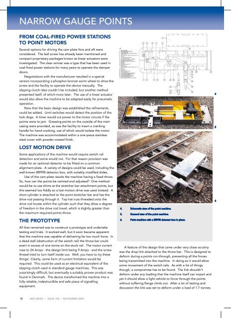
4. Schematic view of the point machine.<br />
5. General view of the point machine.<br />
6. Point machine with a BR998 detector box in place.<br />
A feature of the design that came under very close scrutiny<br />
was the drop link attached to the throw bar. This is designed to<br />
deform during a points run-through, preventing all the forces<br />
being transmitted into the machine. In doing so it would allow<br />
some movement of the switch rails. As with a lot of things<br />
though, a compromise has to be found. The link shouldn’t<br />
deform under any loading that the machine itself can impart and<br />
yet it should allow a light vehicle to force through the points<br />
without suffering flange climb out. After a lot of testing and<br />
discussion the link was set to deform under a load of 1.7 tonnes.<br />
4<br />
5<br />
6<br />
30<br />
<strong>IRSE</strong> NEWS | ISSUE <strong>150</strong> | NOVEMBER 2009