

4700 Refrigeration Module - 234 VAC - Isco
4700 Refrigeration Module - 234 VAC - Isco
4700 Refrigeration Module - 234 VAC - Isco

Create successful ePaper yourself
Turn your PDF publications into a flip-book with our unique Google optimized e-Paper software.
<strong>4700</strong> 117V <strong>Refrigeration</strong> <strong>Module</strong><br />
Removal and Replacement<br />
Instruction Sheet 60-4702-048<br />
Revision C, June 1, 2012<br />
Before attempting to remove and replace a module<br />
observe the following precautions:<br />
WARNING<br />
Removing a module exposes you to electrical and<br />
mechanical hazards. Always disconnect the AC<br />
power cord before attempting to remove any<br />
module. Only trained service personnel may<br />
remove or replace these modules.<br />
CAUTION<br />
Removing the sealed modules will expose the internal<br />
components. Wet or corrosive atmospheres may attack<br />
the exposed refrigerator components. Always service<br />
modules in a dry, corrosion-free environment.<br />
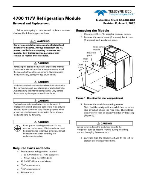
Removing the <strong>Module</strong><br />
1. Disconnect the <strong>4700</strong> sampler from AC power.<br />
2. Remove the cover brace (2 screws), back cover<br />
(5 screws), and insulation panel.<br />
<strong>Refrigeration</strong><br />
module<br />
Insulation<br />
panel<br />
Back<br />
cover<br />
Cover<br />
brace<br />
CAUTION<br />
<strong>Module</strong>s contain circuit boards and sensitive electronics<br />
that can be damaged by a discharge of static electricity.<br />
Avoid touching the internal components. Only handle<br />
the module by the edges or exterior surfaces.<br />
CAUTION<br />
Electrical connectors and wires can be damaged if<br />
improperly handled. Electrical connectors must only be<br />
handled by the connector body. Never grasp the wires<br />
or use tools to disconnect a connector. Never allow a<br />
module to hang by its wiring.<br />
CAUTION<br />
Earth ground bonding conductor. Do not<br />
remove or disconnect. If this conductor must<br />
be disconnected to remove a module, it must<br />
be reconnected when installing the<br />
replacement module.<br />
Figure 1: Opening the rear compartment<br />
3. Remove the module mounting screws.<br />
Note that the refrigeration module has an adhesive<br />
strip just above the rear coils. The bottom<br />
center screw may be slightly hidden by this strip<br />
(Figure 2).<br />
CAUTION<br />
During removal, keep the module as close to the<br />
refrigerator body as possible to avoid pulling the wiring<br />
taut and damaging the connectors.<br />
4. Carefully turn the module out and to the left to<br />
expose the wiring connectors.<br />
Required Parts and Tools<br />
●<br />
●<br />
●<br />
●<br />
●<br />
Replacement refrigeration module:<br />
❍ 60-4704-028 for 117 <strong>VAC</strong> samplers<br />
❍ Nylon cable tie 489-0110-00<br />
#2 & #3 Phillips screwdrivers<br />
15 /16" open wrench<br />
11 /32" open wrench<br />
Wire cutters
Instruction Sheet 60-4702-048 Revision C, June 1, 2012 Page 2<br />
Adhesive<br />
strip<br />
Figure 2: Removing the refrigeration module<br />
Figure 4: Accessing compressor overload and<br />
relay A screwdriver may be used to release the latch.<br />
6. While holding the overload and relay in place,<br />
disconnect solid brown wire. Disconnect the<br />
solid blue wire. With the 11 /32" wrench, remove<br />
the nut holding the green and yellow ground<br />
wire on the module chassis (Figure 5). (These<br />
connections are from the power supply on the<br />
rear of the cabinet and will vary according to the<br />
type of capacitor.)<br />
Figure 3: <strong>Module</strong> removed<br />
Disconnect<br />
wires<br />
(older units)<br />
Brown<br />
Blue<br />
Green/<br />
yellow<br />
Old<br />
capacitor<br />
5. Remove the terminal cover of the compressor<br />
(Figure 4).<br />
Disconnect<br />
wires<br />
(newer units)<br />
Brown<br />
Blue<br />
Green/<br />
yellow<br />
New<br />
capacitor<br />
and relay<br />
Figure 5: Disconnect line cord wires
Page 3 Instruction Sheet 60-4702-048 Revision C, June 1, 2012<br />
7. The evaporator sensor is mounted on the sixth<br />
coil up on the evaporator (see Figure 6). Note<br />
that some older models have a metal sensor,<br />
while current models have a black rubber<br />
molded housing. Cut the ties holding the evaporator<br />
sensor in place and move it out of the<br />
frame.<br />
Bushing<br />
Figure 8: Removing line cord from module<br />
<strong>Module</strong> Replacement<br />
Ensure that the control wiring runs through the<br />
channels in the refrigerator body. The refrigeration<br />
module and rear compartment have adhesive strips and<br />
Permagum 1 (caulking cord sealant) protecting the components.<br />
Ensure that all adhesive strips and<br />
Permagum are still in place before reassembly.<br />
Older<br />
Figure 6: Removing evaporator temp sensor Cut<br />
cable ties<br />
8. Cut the cable tie holding the power cord that<br />
runs through the refrigeration assembly.<br />
Cut cable<br />
tie<br />
Current<br />
CAUTION<br />
The adhesive strips and Permagum are required to<br />
prevent air flow between the condenser coil and the<br />
evaporator plate. Without this protection, condensation<br />
on the coil will cause ice build-up, resulting in poor<br />
refrigerator performance and inability to shut off.<br />
Note<br />
Two thick, black cables connect the power supply with<br />
the AC and compressor. Ensure that cables are side<br />
by side and not crossed during reassembly.<br />
Figure 7: Cut cable tie to free power cord<br />
9. Remove the power cord from the refrigeration<br />
assembly.<br />
a. Slide the bushing sideways away from the<br />
refrigeration module until it is free. Use care<br />
to avoid bending the refrigeration tubing.<br />
b. Pull the power cord through the module.<br />
Permagum<br />
sealant<br />
Power supply cables<br />
Figure 9: Rear view with module removed<br />
Adhesive strips<br />
1. Permagum is a registered trademark of the Presstite Engineering<br />
Company.
Instruction Sheet 60-4702-048 Revision C, June 1, 2012 Page 4<br />
Permagum<br />
sealant<br />
Adhesive<br />
strip<br />
Center<br />
screw<br />
c. With the 11 /32" wrench, connect the green and<br />
yellow ground wire with the nut to the<br />
threaded standoff on the frame.<br />
4. Reinstall the wiring cover that was removed in<br />
step 5 in the previous section.<br />
CAUTION<br />
Earth ground bonding conductor. Ensure that<br />
the green/yellow wire is reconnected to this<br />
terminal.<br />
Figure 10: Rear view of refrigeration module<br />
5. Move the refrigeration module up to the rear of<br />
the refrigerator and replace the drain tube in the<br />
drip pan on the module.<br />
1. Route the AC power cord through the refrigeration<br />
module and secure it in place with the bushing<br />
and cable tie 489-0110-00.<br />
Bushing<br />
Cable Tie<br />
Figure 12: Position drain tube in front half of drip pan.<br />
Figure 11: Secure AC Power Cord 1.with bushing and<br />
cable tie<br />
2. Install the evaporator temperature sensor at the<br />
top of the sixth coil (Figure 6), using the cable<br />
ties provided.<br />
To operate correctly the sensor must be<br />
mounted in the exact position illustrated in Figure<br />
6.<br />
Note<br />
If installing the black molded<br />
sensor, be careful not to<br />
overtighten the cable tie on the<br />
sensor body, as internal<br />
damage could occur.The sensor<br />
should be snug against the coil,<br />
but the rubber housing should<br />
not be visibly dented.<br />
CAUTION<br />
When reinstalling the refrigeration module, use caution<br />
not to pinch the sensor wiring.<br />
6. Install the module, tipping the top back while<br />
sliding the bottom forward. When the bottom of<br />
the system is in place, push the top into place.<br />
(2)<br />
3. Connect the compressor power wires (refer to<br />
Figure 5, lower image):<br />
a. Connect the brown wire to the overload (top).<br />
b. Connect the blue wire to the blue wire from<br />
the new capacitor and relay.<br />
(1)<br />
Figure 13: Slide module into place
Instruction Sheet 60-4702-048 Revision C, June 1, 2012<br />
CAUTION<br />
When reinstalling all self-tapping screws, avoid<br />
destroying the plastic threads. First seat each screw in<br />
its hole and, without pressing down, rotate the screw<br />
counter-clockwise until it falls into its thread groove with<br />
a “click.”Then tighten the screw.<br />
7. Reinstall the refrigeration module mounting<br />
screws (8), insulation panel/back cover screws<br />
(5), and cover brace screws (2).<br />
8. Restore AC power to the <strong>4700</strong> refrigerator.<br />
9. After 30 minutes, perform the refrigerator<br />
temperature diagnostic test, as described in<br />
the following section.<br />
RefrigeratorTemperature Diagnostic<br />
The REFRIG TEMPERATURE diagnostic displays the temperature<br />
of the refrigerated compartment.<br />
To start the diagnostics from the standby screen:<br />
1. Select the CONFIGURE option and press Enter.<br />
PROGRAM CONFIGURE<br />
VIEW LOG<br />
As the refrigerator cycles off and on, the reported<br />
temperature will rise above and below the set temperature.<br />
However, the average reported temperature should<br />
be the same as the configured temperature. The evaporator<br />
temperature may at times read as low as –20 °C;<br />
this is considered normal.<br />
If the screen displays an asterisk (*) or inaccurate<br />
temperature reading, the temperature sensor cable<br />
may be malfunctioning.<br />
2. Press the left arrow button until the RUN DIAG-<br />
NOSTICS option is displayed. Press Enter.<br />
SELECT OPTION: ()<br />
RUN DIAGNOSTICS<br />
SELECT DIAG: ()<br />
TEST 'RAM'<br />
3. Press the right arrow key 7 times to display<br />
REFRIG TEMPERATURE. Press Enter to start the test.<br />
Last modified May 18, 2012<br />
SELECT DIAG: ()<br />
REFRIG TEMPERATURE<br />
When this test is started, the sampler should display<br />
the temperature until you press the Stop or Enter<br />
button. There is no pass or fail. This test simply provides<br />
continuous temperature monitoring.<br />
REFRIG TEMPERATURE:<br />
AIR=__C EVAP=__C<br />
Teledyne <strong>Isco</strong><br />
P.O. Box 82531, Lincoln, Nebraska, 68501 USA<br />
Toll-free: (866) 298-6174 • Phone: (402) 464-0231 • Fax: (402) 465-3001<br />
E-mail: <strong>Isco</strong>Service@teledyne.com<br />
Teledyne <strong>Isco</strong> is continually improving its products and reserves the right to change product<br />
specifications, replacement parts, schematics, and instructions without notice.


