

6100CR Refrigerated Sampler - Isco
6100CR Refrigerated Sampler - Isco
6100CR Refrigerated Sampler - Isco

You also want an ePaper? Increase the reach of your titles
YUMPU automatically turns print PDFs into web optimized ePapers that Google loves.
<strong>6100CR</strong> <strong>Refrigerated</strong><br />
<strong>Sampler</strong><br />
Installation and Operation Guide<br />
Part #69-6103-028 of Assembly #60-6104-017<br />
Copyright © 2000. All rights reserved, Teledyne <strong>Isco</strong>, Inc.<br />
Revision H, July 20, 2005
Foreword<br />
This instruction manual is designed to help you gain a thorough understanding of the<br />
operation of the equipment. Teledyne <strong>Isco</strong> recommends that you read this manual<br />
completely before placing the equipment in service.<br />
Although Teledyne <strong>Isco</strong> designs reliability into all equipment, there is always the possibility<br />
of a malfunction. This manual may help in diagnosing and repairing the malfunction.<br />
If the problem persists, call or e-mail the Teledyne <strong>Isco</strong> Customer Service Department<br />
for assistance. Contact information is provided below. Simple difficulties can often be<br />
diagnosed over the phone. If it is necessary to return the equipment to the factory for<br />
service, please follow the shipping instructions provided by the Customer Service<br />
Department, including the use of the Return Authorization Number specified. Be<br />
sure to include a note describing the malfunction. This will aid in the prompt<br />
repair and return of the equipment.<br />
Teledyne <strong>Isco</strong> welcomes suggestions that would improve the information presented in<br />
this manual or enhance the operation of the equipment itself.<br />
Teledyne <strong>Isco</strong> is continually improving its products and reserves the right to<br />
change product specifications, replacement parts, schematics, and instructions<br />
without notice.<br />
Contact Information<br />
Phone: (800) 228-4373 (USA, Canada, Mexico)<br />
(402) 464-0231 (Outside North America)<br />
Repair Service: (800) 775-2965 (Analytical and Process<br />
Monitoring Instruments)<br />
(800) 228-4373 (<strong>Sampler</strong>s and Flow Meters)<br />
Fax: (402) 465-3022<br />
E-mail address: info@isco.com<br />
Web site: www.isco.com<br />
Return equipment to: 4700 Superior Street, Lincoln, NE 68504-1398<br />
Other correspondence: P.O. Box 82531, Lincoln, NE 68501-2531<br />
Revised June 24, 2004
<strong>6100CR</strong> <strong>Refrigerated</strong> <strong>Sampler</strong><br />
Site Requirements Checklist<br />
CAUTION<br />
All items on this checklist must be met before operating the<br />
<strong>6100CR</strong>, or it will not perform as designed. Operation of the<br />
sampler under improper conditions could result in collection of<br />
unrepresentative samples, failure to collect samples, and/or<br />
possible damage to the sampler.<br />
YES<br />
NO<br />
1. Is the source pressure between 2 psi and 100<br />
psi, measured at the sampler?<br />
2. Is the pressure steady, not varying more than<br />
±5 psi (not fluctuating)?<br />
3. If the pressure is less than 15 psi, has a booster<br />
pump been installed?<br />
4. Will the sampler’s ambient temperature during<br />
operation remain between 32°F and 120°F?<br />
5. If the ambient temperature can fall below 32°F,<br />
have you protected the sample lines from freezing?<br />
6. Is the sample source temperature 185°F or<br />
less?<br />
7. Has a shut off valve been installed where the<br />
sample line connects to the source to permit<br />
maintenance?<br />
8. Is the line between the sample source and the<br />
sampler a minimum of 25 ft., but no more than<br />
100 ft. in length?<br />
9. Has the main line filter been installed?<br />
10. Is the overflow drain line 20 ft long (as supplied<br />
by Teledyne <strong>Isco</strong>) and has it been installed on<br />
the restrictor and routed to an open discharge<br />
drain?<br />
11. Have the strainer bypass and overflow drain<br />
lines been routed to open discharge drain?<br />
Note<br />
Any of these criteria not met at the time of installation must be<br />
corrected before operating the sampler.
<strong>6100CR</strong> <strong>Refrigerated</strong> <strong>Sampler</strong><br />
Site Requirements Checklist
<strong>6100CR</strong> <strong>Refrigerated</strong> <strong>Sampler</strong><br />
Table of Contents<br />
Site Requirements Checklist<br />
Section 1 Introduction<br />
1.1 How the <strong>6100CR</strong> Works. . . . . . . . . . . . . . . . . . . . . . . . . . . . . . . . . . . . . . . . . . . . . . 1-1<br />
1.1.1 Connection to Pressurized Line . . . . . . . . . . . . . . . . . . . . . . . . . . . . . . . . . . 1-2<br />
1.1.2 Controller Operation . . . . . . . . . . . . . . . . . . . . . . . . . . . . . . . . . . . . . . . . . . . 1-2<br />
1.2 Quick-Start Operating Procedure . . . . . . . . . . . . . . . . . . . . . . . . . . . . . . . . . . . . . . 1-2<br />
1.3 <strong>Sampler</strong> Unpacking and Setup. . . . . . . . . . . . . . . . . . . . . . . . . . . . . . . . . . . . . . . . . 1-3<br />
1.3.1 Under the Controller Cover . . . . . . . . . . . . . . . . . . . . . . . . . . . . . . . . . . . . . . 1-4<br />
1.3.2 The Bottle Rack . . . . . . . . . . . . . . . . . . . . . . . . . . . . . . . . . . . . . . . . . . . . . . . 1-4<br />
1.3.3 Cleaning the Bottles (the First Time) . . . . . . . . . . . . . . . . . . . . . . . . . . . . . . 1-5<br />
1.3.4 Installing the Bottle Rack . . . . . . . . . . . . . . . . . . . . . . . . . . . . . . . . . . . . . . . 1-5<br />
1.3.5 Attaching the Sample Tubing . . . . . . . . . . . . . . . . . . . . . . . . . . . . . . . . . . . . 1-5<br />
1.3.6 Attaching the Drain Tube . . . . . . . . . . . . . . . . . . . . . . . . . . . . . . . . . . . . . . . 1-5<br />
1.4 Operation and Description of the Display and Keypad. . . . . . . . . . . . . . . . . . . . . . 1-6<br />
1.4.1 Power Up . . . . . . . . . . . . . . . . . . . . . . . . . . . . . . . . . . . . . . . . . . . . . . . . . . . . 1-6<br />
1.4.2 On/Off . . . . . . . . . . . . . . . . . . . . . . . . . . . . . . . . . . . . . . . . . . . . . . . . . . . . . . . 1-8<br />
1.4.3 Program and Setup Keys . . . . . . . . . . . . . . . . . . . . . . . . . . . . . . . . . . . . . . . . 1-8<br />
1.4.4 Program . . . . . . . . . . . . . . . . . . . . . . . . . . . . . . . . . . . . . . . . . . . . . . . . . . . . . 1-8<br />
1.4.5 Setup . . . . . . . . . . . . . . . . . . . . . . . . . . . . . . . . . . . . . . . . . . . . . . . . . . . . . . . . 1-8<br />
1.4.6 Run . . . . . . . . . . . . . . . . . . . . . . . . . . . . . . . . . . . . . . . . . . . . . . . . . . . . . . . . . 1-8<br />
1.4.7 Clear/Exit . . . . . . . . . . . . . . . . . . . . . . . . . . . . . . . . . . . . . . . . . . . . . . . . . . . . 1-8<br />
1.4.8 Enter . . . . . . . . . . . . . . . . . . . . . . . . . . . . . . . . . . . . . . . . . . . . . . . . . . . . . . . . 1-8<br />
1.4.9 Display Status . . . . . . . . . . . . . . . . . . . . . . . . . . . . . . . . . . . . . . . . . . . . . . . . 1-8<br />
1.4.10 Rack Reset . . . . . . . . . . . . . . . . . . . . . . . . . . . . . . . . . . . . . . . . . . . . . . . . . . 1-8<br />
1.4.11 Manual Purge . . . . . . . . . . . . . . . . . . . . . . . . . . . . . . . . . . . . . . . . . . . . . . . 1-9<br />
1.4.12 Manual Sample . . . . . . . . . . . . . . . . . . . . . . . . . . . . . . . . . . . . . . . . . . . . . . 1-9<br />
1.4.13 Operating Principles . . . . . . . . . . . . . . . . . . . . . . . . . . . . . . . . . . . . . . . . . 1-12<br />
Section 2 Programming<br />
2.1 Overview . . . . . . . . . . . . . . . . . . . . . . . . . . . . . . . . . . . . . . . . . . . . . . . . . . . . . . . . . . 2-1<br />
2.1.1 Setup Steps . . . . . . . . . . . . . . . . . . . . . . . . . . . . . . . . . . . . . . . . . . . . . . . . . . 2-1<br />
2.1.2 Program Steps . . . . . . . . . . . . . . . . . . . . . . . . . . . . . . . . . . . . . . . . . . . . . . . . 2-1<br />
2.1.3 Calibration Steps . . . . . . . . . . . . . . . . . . . . . . . . . . . . . . . . . . . . . . . . . . . . . . 2-1<br />
2.2 Program Displays . . . . . . . . . . . . . . . . . . . . . . . . . . . . . . . . . . . . . . . . . . . . . . . . . . . 2-2<br />
2.3 The SETUP Sequence . . . . . . . . . . . . . . . . . . . . . . . . . . . . . . . . . . . . . . . . . . . . . . . . 2-2<br />
2.4 The PROGRAM Sequence. . . . . . . . . . . . . . . . . . . . . . . . . . . . . . . . . . . . . . . . . . . . . 2-9<br />
2.5 The RUN Key . . . . . . . . . . . . . . . . . . . . . . . . . . . . . . . . . . . . . . . . . . . . . . . . . . . . . 2-11<br />
2.6 Active State Displays (Run Mode) . . . . . . . . . . . . . . . . . . . . . . . . . . . . . . . . . . . . . 2-13<br />
2.7 <strong>Sampler</strong> Response to Power Failures. . . . . . . . . . . . . . . . . . . . . . . . . . . . . . . . . . . 2-15<br />
2.8 Error Messages . . . . . . . . . . . . . . . . . . . . . . . . . . . . . . . . . . . . . . . . . . . . . . . . . . . . 2-16<br />
2.9 The Display Status Key and the History Log . . . . . . . . . . . . . . . . . . . . . . . . . . . . 2-16<br />
2.10 Quick View of Sampling Sequences Only . . . . . . . . . . . . . . . . . . . . . . . . . . . . . . 2-17<br />
2.11 The Display Status Screens . . . . . . . . . . . . . . . . . . . . . . . . . . . . . . . . . . . . . . . . . 2-17<br />
i
<strong>6100CR</strong> <strong>Refrigerated</strong> <strong>Sampler</strong><br />
Table of Contents<br />
Section 3 Installation of the <strong>Sampler</strong><br />
3.1 Installation Guidelines . . . . . . . . . . . . . . . . . . . . . . . . . . . . . . . . . . . . . . . . . . . . . . . 3-1<br />
3.1.1 Connection of the Sample Line . . . . . . . . . . . . . . . . . . . . . . . . . . . . . . . . . . . 3-1<br />
3.1.2 Preparation of Tubing and Connectors . . . . . . . . . . . . . . . . . . . . . . . . . . . . . 3-4<br />
3.1.3 Tubing Connection from Filter to Regulator . . . . . . . . . . . . . . . . . . . . . . . . 3-5<br />
3.2 Connection to a Flow Meter . . . . . . . . . . . . . . . . . . . . . . . . . . . . . . . . . . . . . . . . . . . 3-7<br />
3.2.1 Connection to a Non-<strong>Isco</strong> Flow Meter . . . . . . . . . . . . . . . . . . . . . . . . . . . . . . 3-8<br />
3.3 Event Mark and Bottle Number Timing . . . . . . . . . . . . . . . . . . . . . . . . . . . . . . . . . 3-9<br />
3.3.1 Sample Considerations . . . . . . . . . . . . . . . . . . . . . . . . . . . . . . . . . . . . . . . . . 3-9<br />
3.4 Handling the Samples. . . . . . . . . . . . . . . . . . . . . . . . . . . . . . . . . . . . . . . . . . . . . . . . 3-9<br />
3.4.1 Cooling the Samples . . . . . . . . . . . . . . . . . . . . . . . . . . . . . . . . . . . . . . . . . . . 3-9<br />
3.4.2 Shipping the Bottle Rack . . . . . . . . . . . . . . . . . . . . . . . . . . . . . . . . . . . . . . . . 3-9<br />
3.4.3 Cleaning the Bottles . . . . . . . . . . . . . . . . . . . . . . . . . . . . . . . . . . . . . . . . . . 3-10<br />
3.5 The Booster Pump. . . . . . . . . . . . . . . . . . . . . . . . . . . . . . . . . . . . . . . . . . . . . . . . . . 3-11<br />
Section 4 Maintenance and Special Features<br />
4.1 Replacing the<br />
Needle Assembly. . . . . . . . . . . . . . . . . . . . . . . . . . . . . . . . . . . . . . . . . . . . . . . . . . . . 4-1<br />
4.2 Needle Alignment . . . . . . . . . . . . . . . . . . . . . . . . . . . . . . . . . . . . . . . . . . . . . . . . . . . 4-3<br />
4.3 Hard Reset. . . . . . . . . . . . . . . . . . . . . . . . . . . . . . . . . . . . . . . . . . . . . . . . . . . . . . . . . 4-4<br />
4.4 Replacing the Desiccant Bags. . . . . . . . . . . . . . . . . . . . . . . . . . . . . . . . . . . . . . . . . . 4-4<br />
4.4.1 Regenerating the Desiccant Bags . . . . . . . . . . . . . . . . . . . . . . . . . . . . . . . . . 4-6<br />
4.5 FLASH Memory Updates . . . . . . . . . . . . . . . . . . . . . . . . . . . . . . . . . . . . . . . . . . . . . 4-6<br />
4.5.1 Running UPDATE . . . . . . . . . . . . . . . . . . . . . . . . . . . . . . . . . . . . . . . . . . . . . 4-7<br />
4.5.2 Setting Preferences . . . . . . . . . . . . . . . . . . . . . . . . . . . . . . . . . . . . . . . . . . . . 4-8<br />
Appendix A Replacement Parts List<br />
A.1 Replacement Parts . . . . . . . . . . . . . . . . . . . . . . . . . . . . . . . . . . . . . . . . . . . . . . . . . . A-1<br />
Appendix B Material Safety Data Sheets<br />
B.1 Material Safety Data Sheets . . . . . . . . . . . . . . . . . . . . . . . . . . . . . . . . . . . . . . . . . . B-1<br />
List of Figures<br />
1-1 <strong>6100CR</strong> <strong>Refrigerated</strong> <strong>Sampler</strong> . . . . . . . . . . . . . . . . . . . . . . . . . . . . . . . . . . . . . . . . . 1-1<br />
1-2 Proper Valve Orientation . . . . . . . . . . . . . . . . . . . . . . . . . . . . . . . . . . . . . . . . . . . . . 1-3<br />
1-3 Keypad of the <strong>6100CR</strong> . . . . . . . . . . . . . . . . . . . . . . . . . . . . . . . . . . . . . . . . . . . . . . . 1-6<br />
1-4 Interior View of <strong>6100CR</strong> <strong>Sampler</strong> . . . . . . . . . . . . . . . . . . . . . . . . . . . . . . . . . . . . 1-11<br />
1-5 Flow Diagram for the <strong>6100CR</strong> . . . . . . . . . . . . . . . . . . . . . . . . . . . . . . . . . . . . . . . . 1-12<br />
3-1 Location of Sample Line Filter on Refrigerator . . . . . . . . . . . . . . . . . . . . . . . . . . . 3-2<br />
3-2 Detail of Filter Installation . . . . . . . . . . . . . . . . . . . . . . . . . . . . . . . . . . . . . . . . . . . 3-3<br />
3-3 Filter, Disassembled . . . . . . . . . . . . . . . . . . . . . . . . . . . . . . . . . . . . . . . . . . . . . . . . 3-4<br />
3-4 Fitting, Disassembled . . . . . . . . . . . . . . . . . . . . . . . . . . . . . . . . . . . . . . . . . . . . . . . 3-4<br />
3-5 The Scoring Tool . . . . . . . . . . . . . . . . . . . . . . . . . . . . . . . . . . . . . . . . . . . . . . . . . . . . 3-5<br />
3-6 Pressure Regulator . . . . . . . . . . . . . . . . . . . . . . . . . . . . . . . . . . . . . . . . . . . . . . . . . . 3-6<br />
3-7 Sample Line from Sample Valve . . . . . . . . . . . . . . . . . . . . . . . . . . . . . . . . . . . . . . . 3-7<br />
3-8 <strong>6100CR</strong> with Booster Pump Installed . . . . . . . . . . . . . . . . . . . . . . . . . . . . . . . . . . 3-12<br />
3-9 Booster Pump Components . . . . . . . . . . . . . . . . . . . . . . . . . . . . . . . . . . . . . . . . . . 3-12<br />
4-1 Tower Mechanism Showing Location of the Needle Assembly . . . . . . . . . . . . . . . 4-1<br />
4-2 Needle Assembly Completed . . . . . . . . . . . . . . . . . . . . . . . . . . . . . . . . . . . . . . . . . . 4-3<br />
4-3 Needle Assembly Parts . . . . . . . . . . . . . . . . . . . . . . . . . . . . . . . . . . . . . . . . . . . . . . 4-3<br />
4-4 Preferences Screen . . . . . . . . . . . . . . . . . . . . . . . . . . . . . . . . . . . . . . . . . . . . . . . . . . 4-9<br />
ii
<strong>6100CR</strong> <strong>Refrigerated</strong> <strong>Sampler</strong><br />
Table of Contents<br />
List of Tables<br />
1-1 <strong>Isco</strong> <strong>6100CR</strong> Cluster Rule <strong>Sampler</strong> Specifications . . . . . . . . . . . . . . . . . . . . . . . . 1-13<br />
4-1 Minimum DOS and Computer Hardware Requirements for FLASH Update . . . 4-9<br />
iii
<strong>6100CR</strong> <strong>Refrigerated</strong> <strong>Sampler</strong><br />
Table of Contents<br />
iv
<strong>6100CR</strong> <strong>Refrigerated</strong> <strong>Sampler</strong><br />
Section 1 Introduction<br />
Note<br />
Never install the <strong>Refrigerated</strong> <strong>6100CR</strong> <strong>Sampler</strong> where there is<br />
any possibility of submersion. The electronic components are<br />
environmentally sealed, but the mechanical components cannot<br />
be. The linkages and moving parts inside the controller can<br />
be damaged by submersion. Parts of the refrigeration mechanism<br />
can also be damaged by submersion, particularly the<br />
condenser fan. Exposure of the mechanical parts to water will<br />
void the warranty.<br />
1.1 How the <strong>6100CR</strong><br />
Works<br />
The <strong>6100CR</strong> <strong>Refrigerated</strong> Volatile Organic <strong>Sampler</strong> consists of a<br />
6100VOC <strong>Sampler</strong> mechanism installed inside a refrigerator.<br />
The primary purpose of this sampler is to monitor VOC concentrations<br />
in waste discharge effluent from bleaching operations at<br />
paper pulp mills. Continuous sample fed from a pressurized<br />
effluent line is periodically injected by needle into sample bottles<br />
that are sealed before and after the sample is taken to prevent<br />
contamination. Location of the sample bottle rack inside the<br />
refrigerator ensures rapid cooling of the sample, which also<br />
retards its decomposition.<br />
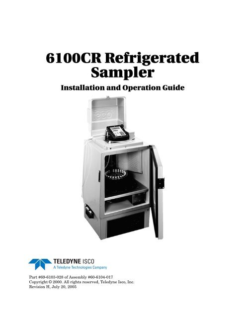
Figure 1-1 <strong>6100CR</strong> <strong>Refrigerated</strong> <strong>Sampler</strong><br />
1-1
<strong>6100CR</strong> <strong>Refrigerated</strong> <strong>Sampler</strong><br />
Section 1 Introduction<br />
1.1.1 Connection to<br />
Pressurized Line<br />
The <strong>Refrigerated</strong> <strong>Sampler</strong> is permanently connected to a pressurized<br />
discharge line from which the sample liquid is periodically<br />
drawn. A filter on this line prevents any solids present in<br />
the effluent from entering the sampler. A valve allows sample to<br />
flow only when the <strong>6100CR</strong> needs to take a sample. A pressure<br />
regulator reduces the line pressure to a safe fill value. Once<br />
inside the refrigerated sampler, the sample flows through a serpentine<br />
coil inside an aluminum container (the ballast) at the<br />
bottom of the refrigerator for cooling before injection into the<br />
sample vials. Waste sample is discharged from the drain line.<br />
1.1.2 Controller Operation The microprocessor in the controller governs the operation of the<br />
mechanism that selects, opens, fills, and closes the sample<br />
bottles. A motor rotates the bottle rack placing each bottle<br />
directly under the fill mechanism. The bottle rack is kept chilled<br />
by its location inside the refrigerator. When the filled rack is sent<br />
to a lab for analysis, it may be kept cold by filling the inside of<br />
the rack with ice and placing in the styrofoam mailer to keep<br />
samples cool during the transport to the lab for analysis.<br />
The fill operation consists of:<br />
• Purging the sample line<br />
• Rotating the bottle rack to place the bottle in position for<br />
filling<br />
• Opening the valve on the sample bottle cap<br />
• Lowering the fill needle into the sample bottle<br />
• Filling the sample bottle with the liquid sample<br />
• Withdrawing the fill needle from the sample bottle<br />
• Closing the valve on the sample bottle<br />
When filling the sample bottle, the <strong>6100CR</strong> actually overflows<br />
the bottle to comply with EPA protocol to fill and dump the<br />
sample bottle. This overfilling keeps residual air pockets from<br />
remaining between the bottle and the lid, thus providing a representative<br />
sample. The excess water drains out of the sampler<br />
through an overflow tube attached to a fitting on the back of the<br />
controller. The controller also determines, through programming,<br />
when and how the <strong>6100CR</strong> takes its samples.<br />
1.2 Quick-Start Operating<br />
Procedure<br />
Note that the quick-start procedure assumes you have some<br />
familiarity with the unit. If you do not, please do not try to<br />
operate the unit without first reading this entire document.<br />
1. Put a new bottle rack in the unit. Make sure the handles<br />
on the bottles are all closed (turned sideways 90° to the<br />
bottles). See Figure 1-2. Improperly oriented handles will<br />
jam the unit.<br />
2. Turn the unit on by pressing the On/Off key on the keypad.<br />
When the unit is off, the display will be blank. When<br />
the unit is on, there will always be something on the display.<br />
1-2
<strong>6100CR</strong> <strong>Refrigerated</strong> <strong>Sampler</strong><br />
Section 1 Introduction<br />
3. If you have not previously set up the sampler’s operation or<br />
if you want to change the setup, press the Setup key to<br />
access the setup menus.<br />
4. Press the Program key to select the type of sample pacing,<br />
number of sample events, start time, etc.<br />
5. Turn on the valve at source, calibrate the flow rate and<br />
route the drain lines from the sampler.<br />
6. Press the Run key to start the sampling sequence you<br />
have programmed into the sampler. The sampler cannot<br />
run its own program until you press Run.<br />
7. When the sampler completes the program you entered, the<br />
display will read:<br />
DONE... XX SAMPLES<br />
(time & date)<br />
8. Press the Rack Reset key to move the rack to the home<br />
position so you can remove the rack from the sampler.<br />
9. Remove the filled bottle rack from the sampler.<br />
10. Turn the unit off with the On/Off key.<br />
11. If you want to run another sampling routine, repeat the<br />
process from step 1.<br />
Right (closed)<br />
Wrong (open)<br />
Sample bottle cap,<br />
viewed from side<br />
Figure 1-2 Proper Valve Orientation<br />
1.3 <strong>Sampler</strong> Unpacking<br />
and Setup<br />
Teledyne <strong>Isco</strong> ships the <strong>6100CR</strong> in a box with special inserts,<br />
and we suggest keeping all packing materials in case returning<br />
the unit for service ever becomes necessary. The bottle rack and<br />
accessories are shipped separately.<br />
1. The rack and bottles come in a mailer. You will use these<br />
items to transport the bottle rack and also to ship the samples<br />
to the lab for analysis. The bottle rack is shipped with<br />
all the bottles installed and held in place under a stainless<br />
steel cover.<br />
1-3
<strong>6100CR</strong> <strong>Refrigerated</strong> <strong>Sampler</strong><br />
Section 1 Introduction<br />
2. Unpack the box carefully, checking for any possible shipping<br />
damage.<br />
3. Remove the tower shipping support. Reinstall the black<br />
knob taken off when removing the support.<br />
1.3.1 Under the Controller<br />
Cover<br />
When you have opened the cover over the controller, the most<br />
prominent features inside are the keypad and display. You<br />
program the sampler using the keypad and prompts from the<br />
display.<br />
Inside the refrigerator behind the sample bottle rack is a rectangular<br />
protrusion with a yellow warning label on it. This is the<br />
housing for the fill needle. When the sampler is in operation, the<br />
fill needle raises and lowers automatically to inject the liquid<br />
sample into the bottles in the rack.<br />
The warning label is to warn you against putting your hand<br />
between the tower and the bottle rack. You can be seriously<br />
injured by the needle coming down when the sampler is in operation.<br />
WARNING<br />
Never place your hand or any other body parts between the<br />
needle assembly and the bottle rack. If the sampler starts<br />
unexpectedly, it will lower the needle to fill a bottle. You<br />
could suffer serious personal injury if your hand is caught<br />
between the needle and the bottle rack. The needle comes<br />
down with enough force to cause serious injury. In order to<br />
avoid damage, always make sure bottle rack is in place,<br />
bottles are in all 24 positions, and the shut-off handles on<br />
all bottles are horizontal.<br />
1.3.2 The Bottle Rack Teledyne <strong>Isco</strong> ships the bottle rack separately from the sampler<br />
for protection. Because of the carrier’s insulating properties you<br />
can pack the bottle rack with ice (or gel packs if you are<br />
shipping) to keep the samples cool from when they are gathered<br />
to when they are analyzed at the laboratory. (Gel packs are a<br />
packaged cooling agent.)<br />
It is very important to keep the samples cool to keep them representative;<br />
heat drives volatile organic compounds out of solution.<br />
The metal plate holding the bottles inside the bottle rack keeps<br />
the bottles in place during shipment and use. It prolongs the<br />
melting time of the ice. The knurled knob with the threaded<br />
shaft attaches the bottle rack to the controller. Never operate the<br />
sampler without the stainless steel cover in place and the knob<br />
securely tightened. Before installing the bottle rack, look at the<br />
tops of the bottles. Make sure all the valve handles on the bottles<br />
are turned so they are perpendicular to the standing bottles, or<br />
facing 3 and 9 o’clock. (See Figure 1-2.)<br />
This is important, not only for proper alignment for sampling,<br />
but also to ensure thst all bottles are closed and free from contamination.<br />
During normal operation, the sampler may occasionally<br />
leak a small amount of sample around the O-ring on the<br />
1-4
<strong>6100CR</strong> <strong>Refrigerated</strong> <strong>Sampler</strong><br />
Section 1 Introduction<br />
tip of the needle. This is generally due to a misalignment<br />
between the needle and the bottle. The small leak does not affect<br />
sample integrity, as it occurs outside the bottle before the valve is<br />
closed. If the leak condition persists or sample is being sprayed<br />
out of this connection, consult Teledyne <strong>Isco</strong> Customer Service. A<br />
leak around the valve stem on the top of the bottle indicates a<br />
worn valve. When this occurs, the valve body must be replaced.<br />
One bottle does not have a valve on top. This is the blank, and<br />
you will also notice that the bottle rack looks different behind<br />
this bottle. There is no slot in the rack. This bottle marks the<br />
home position for the bottle rack. When you reload the bottles<br />
after sampling always put the blank bottle back in this position,<br />
or the sampler will not work properly.<br />
1.3.3 Cleaning the Bottles<br />
(the First Time)<br />
Teledyne <strong>Isco</strong> assembles the racks with new clean bottles, as<br />
shipped from the bottle manufacturer. Normally, no further<br />
cleaning is necessary before first use of the bottles. However,<br />
these bottles and valves are not certified clean. If you wish to<br />
clean the bottles before using them the first time (for example if<br />
you are sampling for extremely low concentration volatile<br />
organic compounds), you may want to clean them. Follow EPA<br />
guidelines for washing and drying the bottles. After you have<br />
used the bottles for samples, always wash and dry them<br />
according to EPA guidelines.<br />
CAUTION<br />
Always make sure the rack is in the "home" position before<br />
installing or removing the bottle rack. This places the blank bottle<br />
under the fill needle. If the rack is not in "home" position,<br />
press Rack Reset to return the rack before removing or installing<br />
the bottle rack. If you do this, the rack will always be in the<br />
right position when you reload it.<br />
1.3.4 Installing the Bottle<br />
Rack<br />
1.3.5 Attaching the Sample<br />
Tubing<br />
1.3.6 Attaching the Drain<br />
Tube<br />
Notice the D-shaped steel shaft in the center of the triangle<br />
formed by the three knobs. This is the bottle rack shaft. Place the<br />
bottle rack over this shaft, rotating it slowly until the D-shape of<br />
the shaft lines up with the same D-shape on the bottom of the<br />
bottle rack. The rack will easily settle into place. Secure the rack<br />
in place by tightening the knurled knob and threaded shaft into<br />
the threaded hole on the D-shaped shaft on the controller base.<br />
The rack is now ready to take samples.<br />
The <strong>6100CR</strong> uses Teflon 1 bonded polyethylene tubing to connect<br />
to the source and to the filter. Connection of the tubing is with<br />
1 /4" tubing fittings.<br />
Teledyne <strong>Isco</strong> supplies a 20 foot length of 1 /4" OD vinyl tubing to<br />
drain the sampler overfill and sample line bypass drain into any<br />
convenient place that gets the water out of the way, and cannot<br />
flow back toward the <strong>6100CR</strong>. There is a restrictor in the end of<br />
the drain line. This must remain in place.<br />
1. Teflon ® , registered trademark of du Pont de Nemours, Inc.<br />
1-5
<strong>6100CR</strong> <strong>Refrigerated</strong> <strong>Sampler</strong><br />
Section 1 Introduction<br />
Figure 1-3 Keypad of the <strong>6100CR</strong><br />
1.4 Operation and<br />
Description of the<br />
Display and Keypad<br />
After you have connected the sampler as described in the previous<br />
sections, you are ready to program the unit to run a sampling<br />
routine. But first you must familiarize yourself with the<br />
keypad and display. You program the <strong>6100CR</strong> by pressing the<br />
buttons on the keypad to make appropriate selections from the<br />
choices that appear on the display.<br />
The display is a two-line, 20 character-per-line liquid crystal. The<br />
display is alphanumeric, meaning it can show both letters and<br />
numbers. The display has a backlight feature that allows you to<br />
read it easily in conditions of low light.<br />
When you are programming, in most cases you will select a word<br />
choice from the menus appearing on the display. In some<br />
instances you will have to enter a number. The display will<br />
provide you with a range of appropriate values. The sampler will<br />
reject entry of any numbers outside this range. During programming,<br />
one option for each program step will always be<br />
flashing on and off. This flashing indicates the selection currently<br />
held in memory.<br />
1. Pressing either of the Arrow keys will cause the flashing<br />
to move to the left or right of the currently selected option.<br />
2. Pressing the Enter key on the keypad will cause this new<br />
choice to be entered into the sampler’s memory.<br />
Various keys also control specific sampler operations. Following<br />
is a description of the function for each key on the keypad.<br />
1.4.1 Power Up When you press the On/Off key to turn on the <strong>6100CR</strong>, the unit<br />
can respond in several different ways, depending on what was<br />
happening when the unit was last turned on. Following are the<br />
possible operations the unit can do when you press the On/Off<br />
key:<br />
1. The sampler may test the tower assembly. The sampler<br />
will move the fill head assembly a short distance up and<br />
down and then back up again, coming to rest near the top<br />
stop.<br />
1-6
<strong>6100CR</strong> <strong>Refrigerated</strong> <strong>Sampler</strong><br />
Section 1 Introduction<br />
2. The sampler may test the driver that turns the valve handles<br />
on the sample bottles to open and close them. This<br />
sequence consists of four movements clockwise and counterclockwise<br />
with short pauses between them. You can see<br />
the valve actuator if you look on the inside of the tower,<br />
about the height of the bottle rack. It is round and has two<br />
pins protruding from it.<br />
3. The sampler may move the bottle rack to the next bottle<br />
position. If the bottle rack is somehow stopped so a bottle is<br />
not directly under the fill head, the rack will rotate a few<br />
degrees to position a sample bottle directly under the fill<br />
head.<br />
4. The sampler may reset the bottle rack. This consists of<br />
rotating the bottle rack until the "home" position of the<br />
rack is under the fill head. If the home position of the rack<br />
is close to the fill head, the rack may make more than one<br />
complete rotation the first time power is applied before the<br />
rack stops on the home position.<br />
When you turn the sampler on with the On/Off key, it may do<br />
some of these things or none of them, and this is normal. When<br />
you turn the unit on for the very first time, or if you have done a<br />
hard reset, the sampler will move the bottle rack if necessary. It<br />
will then do a tower test and if that works correctly, it will do a<br />
valve driver test and if that passes, it will do a reset of the bottle<br />
rack, in that order.<br />
Otherwise, when you turn the sampler on, what happens will<br />
depend on the condition it was in when you turned it off. First, it<br />
will check the positioning of the bottle rack to see that there is a<br />
bottle directly under the fill head. If not, the unit will move the<br />
bottle rack.<br />
Then the sampler will check the condition of the tower drive (the<br />
up and down motion of the fill head). If the tower is not in the<br />
“home” position (fully up), or the sampler detected a tower jam on<br />
the last attempt to move the tower, it will do a tower test. If the<br />
tower was in the “home” position or successfully passes the tower<br />
test, the sampler will then look at the condition of the valve<br />
driver. If the valve driver is not in the “home” position or if the<br />
sampler detected a valve driver jam the last time it tried to<br />
rotate the driver, it will do a valve driver test. The unit will not<br />
reset the rack at this time.<br />
If the sampler was in the process of running a sampling program<br />
when it was shut down, a message will appear on the display<br />
saying that the program was aborted and cannot be resumed.<br />
You will have to restart a new program if sampling is to continue.<br />
After the sampler runs these tests, it will be in the standby state,<br />
and the standby message will display on the screen.<br />
At other times when the sampler moves the bottle rack, such as<br />
when you press the Rack Reset key, or the sampler is taking a<br />
sample and must advance the rack to a new bottle, it may do the<br />
tower test or the valve driver test if the associated mechanism is<br />
1-7
<strong>6100CR</strong> <strong>Refrigerated</strong> <strong>Sampler</strong><br />
Section 1 Introduction<br />
not in the home position as described above, or a jam in that<br />
mechanism was detected on the previous attempt to move that<br />
mechanism.<br />
1.4.2 On/Off This key is the master control for the entire system. When you<br />
turn the sampler off, no other key will have any effect, even if you<br />
are in the middle of a sampling routine. However, any program<br />
choices you have made and entered for the sampler setup and<br />
sampling routine will be retained by the unit in battery-backed<br />
memory. Turning on the sampler does not make it run a program.<br />
Turning the sampler on just puts it in the "Standby" state, where<br />
it is ready to receive programming and configuration commands<br />
from the keypad.<br />
1.4.3 Program and Setup<br />
Keys<br />
These keys both control programming of the sampler. Setup configures<br />
the sampler (defines how the sampler will work) while<br />
Program defines the specifics of the sampling routine.<br />
1.4.4 Program This key puts you into the programming mode for the sampler.<br />
For the <strong>6100CR</strong>, “program” refers specifically to the sampling<br />
routine the unit will run. You may change the Program without<br />
changing the Setup.<br />
1.4.5 Setup This key programs the sampler for functions that differ from the<br />
sampling routine controlled by Program. Setup performs the<br />
"housekeeping" functions of the sampler. In Setup you set the<br />
internal clock, establish a site identification number, etc. Note<br />
that you may change Setup without changing items selected in<br />
Program.<br />
1.4.6 Run After you have programmed the sampler with both the Program<br />
and Setup menus, you must press Run for the sampler to run its<br />
program, regardless of when you programmed the routine to<br />
begin. The Run key starts the program.<br />
1.4.7 Clear/Exit Pressing this key allows you a way to revert to a previous entry<br />
for a menu choice, or to exit the Setup or Program menus.<br />
1.4.8 Enter You must press the Enter key to step through the menu for<br />
either the Program or Setup functions. While programming,<br />
pressing Enter will store the choice or value displayed on the<br />
screen and move you to the next choice.<br />
1.4.9 Display Status The <strong>6100CR</strong> keeps a record in memory of programming and<br />
sampling activity called the History Log. It is possible to view<br />
this record screen by screen on the display. If you press this key<br />
when the sampler is turned on and in the Standby operating<br />
mode, it will allow you to view this log. More information on the<br />
History Log, with several representative screens can be found in<br />
this manual in Section 2.9.<br />
1.4.10 Rack Reset Pressing this key when the sampler is in the normal operating<br />
state will return the bottle rack to the "home" position. This is<br />
when the blank bottle is directly under the fill needle. If the<br />
1-8
<strong>6100CR</strong> <strong>Refrigerated</strong> <strong>Sampler</strong><br />
Section 1 Introduction<br />
sampler previously detected a fault in the tower, it will test the<br />
tower before it rotates the rack. The same will occur if the<br />
sampler previously detected a fault in the valve actuator, and the<br />
valve actuator must be returned to the normal position if it is<br />
not. Also, if the needle is not fully raised, the sampler will raise it<br />
before rotating the rack. The sampler raises the needle and<br />
returns the valve actuator to the normal position so they will not<br />
interfere with the rotation of the rack. Rack Reset will not have<br />
an effect when the sampler is in the running state.<br />
1.4.11 Manual Purge Pressing the Manual Purge key when the sampler is in the<br />
standby state will bring up the following screen:<br />
MANUAL PURGE<br />
STRAINER PRE-COOLER<br />
Selecting strainer will cause the sampler to open the flow valve<br />
so liquid will flow from the sample source through the strainer<br />
and valve. The liquid will be diverted by the valve and will not go<br />
through the sample pre-cooler or the actual bottle-filling mechanism,<br />
but will flow out through the bypass drain line. The flow<br />
can be stopped by pressing the ON/OFF key, or the Clear/Exit<br />
key. The Purge will also be stopped after a fifteen minute<br />
time-out. This function is useful for checking out the operation of<br />
the system, as well as purging air from the system after the<br />
strainer housing has been opened for cleaning.<br />
Similarly, selecting PRE-COOLER will cause the sampler to open<br />
the valve so the liquid will flow through the strainer, pre-cooler<br />
and the needle mechanism that fills the sample collection bottles.<br />
None will flow through the bypass. It exits the system through<br />
the sample overflow drain line. This selection does not cause the<br />
sampler to open a sample vial or put the sampling needle mechanism<br />
into a sample vial.<br />
Therefore, no liquid is introduced into a vial and no vials are contaminated<br />
by this operation. This operation is useful to verify<br />
that the system is functional, and that the valves open properly<br />
so the liquid can flow through the system. The operation is also<br />
useful to purge air from the pre-cooler upon initial installation<br />
and if it is drained during subsequent maintenance operations.<br />
The Manual Purge selections can also be useful if the sampler is<br />
not to be used for some period of time and it is desired to flush<br />
the system with clean water. If the inlet line is disconnected from<br />
the sample source and connected to clean water, these selections<br />
will make the sampler open the valves so clean water can flow<br />
through the system.<br />
1.4.12 Manual Sample This key allows you to take a sample any time the <strong>6100CR</strong> is in<br />
Standby, but it will not do manual sample within a running<br />
program. When you press this key, the unit will place a sample in<br />
the next bottle.<br />
1-9
<strong>6100CR</strong> <strong>Refrigerated</strong> <strong>Sampler</strong><br />
Section 1 Introduction<br />
Always make sure that a bottle rack is installed before starting a<br />
manual sample.<br />
CAUTION<br />
The sampler may be damaged if there is no bottle rack<br />
installed when you try to take a sample.<br />
After pressing the Manual Sample key, the following screen will<br />
appear:<br />
BOTTLE RACK LOADED?<br />
YES NO<br />
NO will always be flashing. To proceed with the manual sample,<br />
select YES with the Arrow key and then press Enter. This<br />
screen reminds you to make sure that a bottle rack is in place<br />
before you start to take a manual sample.<br />
Figure 1-4 shows the <strong>6100CR</strong> components inside the refrigerator.<br />
Shown are the needle assembly, the bottle rack and the ballast<br />
assembly. The needle assembly is normally covered with a protective<br />
plastic shield. This is to prevent injury and to protect the<br />
needle fill mechanism as well.<br />
Following are descriptions of the various items called out in<br />
Figure 1-4.<br />
A - Tower assembly with needle mechanism. The needle<br />
raises and lowers to deliver the liquid sample to the sample<br />
bottles.<br />
B - Evaporator (cold plate) of refrigerator. Provides cooling<br />
for inside of refrigerator.<br />
C - Sample Bottle Rack (carousel). Plastic ‘basket’ contains<br />
slots for 25 sample bottles. Plate on top of rack holds bottles<br />
securely. Center of ‘basket’ can be packed with ice or<br />
cold packs to maintain sample integrity en route to lab<br />
analysis.<br />
D - <strong>Sampler</strong> deck, showing location of sample tube and<br />
electrical connections.<br />
1-10
<strong>6100CR</strong> <strong>Refrigerated</strong> <strong>Sampler</strong><br />
Section 1 Introduction<br />
A<br />
B<br />
C<br />
D<br />
E<br />
F<br />
Figure 1-4 Interior View of <strong>6100CR</strong> <strong>Sampler</strong><br />
E - <strong>Sampler</strong> motor housing. Rotates (3), sample bottle rack<br />
to align sample bottle under needle assembly (1).<br />
F - Ballast box. This aluminum box contains a serpentine<br />
coil of sample tubing. Its purpose is to cool the incoming<br />
sample before the sample is injected into the sample bottles.<br />
1-11
<strong>6100CR</strong> <strong>Refrigerated</strong> <strong>Sampler</strong><br />
Section 1 Introduction<br />
C<br />
K<br />
D<br />
G<br />
B<br />
F<br />
E<br />
H<br />
A<br />
I<br />
J<br />
Figure 1-5 Flow Diagram for the <strong>6100CR</strong><br />
1.4.13 Operating Principles A 1 /4" O.D. sample line is connected to the bleach operation<br />
effluent pipe, either alkaline or acidic, (A). Customer-supplied<br />
valve (B) is used to shut down flow to allow maintenance and<br />
service of <strong>6100CR</strong> and associated system components. The<br />
primary filter (C) is in-line to remove any solid material from the<br />
liquid flow that could cause clogging in the sampler. This filter is<br />
of the type that can be disassembled and cleaned periodically.<br />
Regulator (D) is used to throttle down the pressure from the<br />
sample line, which can be as high as 120 psig, to a rate that<br />
allows the sampler to fill the vials at 2 ml/second. Sample valve<br />
(E) depending on its position either sends sample to the sampler<br />
or in the case of a purge, to the drain.<br />
This rate is set by adjusting the regulator in the sampler’s Calibrate<br />
step. The ballast coil (F) allows for cooling of the sample,<br />
which may leave the effluent pipe at temperatures as high as<br />
185°F (85°C). The ballast coil is installed inside the refrigerator,<br />
(G) which supplies the cooling for the sample line, as well as for<br />
the stored samples. Cooled sample is injected into bottles by the<br />
sample needle (H). The valve (I) is automatically opened and<br />
closed by the sampler mechanism for the filling process and to<br />
preclude contamination of the bottled sample once it is collected.<br />
The bottle (J) along with 24 others in the rack are then taken to a<br />
lab for analysis. There is a screen-filter (K) located at the inlet to<br />
regulator D to catch any material that might escape from the<br />
filter C.<br />
1-12
<strong>6100CR</strong> <strong>Refrigerated</strong> <strong>Sampler</strong><br />
Section 1 Introduction<br />
General<br />
Table 1-1 <strong>Isco</strong> <strong>6100CR</strong> Cluster Rule <strong>Sampler</strong> Specifications<br />
Height 47 in. 117 cm<br />
Width 26 in. 66 cm<br />
Depth 26 in. 66 cm<br />
Weight (Dry) 190 lb. 86 kg<br />
Refrigerator Body Material<br />
Power Requirements<br />
Fiberglass-reinforced plastic with UV-resistant gel coat.<br />
120 Volts, 60 Hz<br />
Operational Temperature Range 32° to 120° F 0° to 50° C<br />
Controller<br />
Enclosure Rating<br />
Interfacing<br />
Diagnostics<br />
Clock Accuracy<br />
Sample Collection<br />
Sample (Vial) Volume Vial Capacity<br />
Rinse Cycles<br />
Sample Frequency<br />
Time Mode<br />
Flow Pacing<br />
Sample Pacing<br />
Multiplexing<br />
Sample Line<br />
Self-certified NEMA 4X and IP67<br />
6-pin connector; data output at 2400 baud in ASCII RS-232 format allows<br />
transfer of Program Settings Report, Sampling Results Report, and history<br />
log. Compatible with <strong>Isco</strong> Samplink software.<br />
Tests RAM, ROM, all mechanical drives, display, flow meter interface, and<br />
printer interface.<br />
1 minute per month typical<br />
40 ml (fixed volume)<br />
24 vials with Teflon valves<br />
1 vial reserved as blank for procedural use.<br />
All wetted surfaces automatically rinsed prior to each sample collection<br />
15 minutes to 99 hours 59 minutes, in one minute increments.<br />
Selectable, 1-9,999 pulses in single pulse intervals.<br />
Time or flow. Flow mode paced by pulses from an external flow meter.<br />
Multiple vial per sample event only. As many as 24 vials can be filled by one<br />
sample initiation.<br />
TPE Teflon lined tubing<br />
Sample Source Pressure Minimum 15 psi Maximum 120 psi<br />
Sample Source Temp.<br />
Sample Filter<br />
Sample Pre-cooling<br />
85°C Maximum<br />
Stainless steel in-line cartridge style. 125 ml capacity<br />
Sample pre-cooled to 25°C (for 85° sample source, 40° ambient temperature,<br />
and 2-hour sampling interval ).<br />
1-13
<strong>6100CR</strong> <strong>Refrigerated</strong> <strong>Sampler</strong><br />
Section 1 Introduction<br />
1-14
<strong>6100CR</strong> <strong>Refrigerated</strong> <strong>Sampler</strong><br />
Section 2 Programming<br />
2.1 Overview For quick reference, following is a condensed list of the programming<br />
steps for the <strong>6100CR</strong> <strong>Sampler</strong>.<br />
2.1.1 Setup Steps 1. Calibrate Flow (Yes/No). Yes provides steps through calibration<br />
routine<br />
2. Filter Purge Time, 0-600 seconds. (Time spent purging<br />
liquid through the line and the filter.) This liquid is<br />
bypassed to the drain without passing into the pre-cooler<br />
(ballast) or the sampler, as that would generally overwhelm<br />
the capacity of the pre-cooler.<br />
3. Bottle Volume Flush, 1 /2, 1, 1 1 /2, 2, 2 1 /2. This is the additional<br />
sample that will be flushed through the sample vial<br />
after the vial has been filled.<br />
4. Site ID Number (User selected).<br />
5. Set Clock<br />
6. Run Diagnostics (see text).<br />
7. Select Enable Mode (Error, Skip, Delay)<br />
2.1.2 Program Steps 1. Time/Flow (sample collection mode)<br />
2. Time or Flow Interval (15 minutes to 99 hours, or 1 to<br />
9,999 flow pulses.<br />
3. Sample at Start - Yes/No (Only if flow-paced.)<br />
4. Bottles per Sample Event<br />
5. Number of Sample Events<br />
6. Enter Start Time - Yes/No<br />
2.1.3 Calibration Steps 1. Display Put discharge tube in drain alternates with<br />
Then press Manual Purge.<br />
2. Pressing the Manual Purge opens the flow valve so that<br />
liquid flows through the pre-cooler and sampler. The display<br />
will show: When no bubbles, press Clear/Exit.<br />
3. Pressing the Clear/Exit key stops the flow and displays:<br />
Put Discharge Tube in Grad Cylinder, alternated with:<br />
Then, Press Manual Sample.<br />
4. Pressing Manual Sample will again start the flow for 50<br />
seconds. After this, the user will be given the chance to run<br />
another calibration or continue. The user should measure<br />
the volume in the cylinder and adjust the pressure regulator<br />
to get the flow to within 5 ml of the target 100 ml. Turn-<br />
2-1
<strong>6100CR</strong> <strong>Refrigerated</strong> <strong>Sampler</strong><br />
Section 2 Programming<br />
ing the regulator handle clockwise will increase the flow,<br />
counterclockwise will decrease it.<br />
2.2 Program Displays In the following section, the words printed in capital letters represent<br />
messages the <strong>6100CR</strong> displays as you work through the<br />
Setup and Program routines. You do not have to go into Setup<br />
if all you want to change is something in Program. Likewise, it<br />
is not necessary to work all the way through Program to change<br />
something in Setup. Some lines have XXs or other capital letters<br />
in them. These letters represent variables, such as amounts,<br />
times, and dates. When the sampler is first turned on, the<br />
number and software revision will appear briefly on the display.<br />
ISCO <strong>6100CR</strong><br />
SOFTWARE VERSION X.XX<br />
When the sampler is in the standby state, not running a<br />
program, the following message will appear on the display:<br />
. . . STANDBY . . .<br />
HH:MM:SS<br />
DDMMMYY<br />
There are two programming sequences for the <strong>6100CR</strong>. One<br />
sequence controls the operation of the sampler and is called<br />
Setup. The other sequence is called Program; in Program you<br />
define the sampling program you want to run. The first time you<br />
use the sampler, you need to work through both sequences to correctly<br />
program the sampler to run a sampling routine. After that<br />
you may never need to reprogram the Setup section. As the<br />
various screens appear, the selected entry (the option currently<br />
held in memory) will flash. Use the Arrow keys to move from<br />
one entry to another. Where the display requests a numeric<br />
value, use the Number keys to enter the appropriate value. Use<br />
the Enter key to move to the next menu item. The unit must be<br />
turned on to function.<br />
2.3 The SETUP Sequence 1. If you press the Setup key, the following will appear:<br />
CALIBRATE FLOW RATE<br />
YES NO<br />
Calibration of the flow rate is critical for proper operation<br />
of the <strong>6100CR</strong>. The procedure consists of purging the discharge<br />
line and then adjusting the pressure regulator to<br />
achieve a discharge rate of 2 ml/sec, measured while filling<br />
a graduated cylinder. See the following menus. When calibrating<br />
the flow rate, the drain line and graduated cylinder<br />
should be on the same level as the it will be when in operation.<br />
Also observe that for proper operation, the drain line<br />
2-2
<strong>6100CR</strong> <strong>Refrigerated</strong> <strong>Sampler</strong><br />
Section 2 Programming<br />
should always discharge into a normal, non-pressurized<br />
open drain.<br />
2. If you select YES, the following will appear:<br />
PUT DISCHARGE TUBE IN DRAIN<br />
Alternating with:<br />
Make sure that the sampler drain line is in a suitable<br />
drain and press the Manual Purge key. This will start liquid<br />
flow through the sample cooler and discharge through<br />
the drain line.<br />
Followed by:<br />
THEN,<br />
PRESS MANUAL PURGE<br />
Observe the discharge line. After the air is purged from the<br />
sample cooler, you should only observe a few bubbles in the<br />
sample line. When the air is purged, push Clear/Exit, and<br />
the flow will stop.<br />
Followed by:<br />
WHEN NO BUBBLES<br />
PRESS CLEAR/EXIT<br />
PUT DISCHARGE TUBE<br />
IN GRAD CYLINDER<br />
Alternating with:<br />
THEN,<br />
PRESS MANUAL SAMPLE<br />
Place the discharge tube into a beaker or graduated cylinder.<br />
Place the beaker at the same level as the discharge<br />
tube will be in normal operation. Then press the Manual<br />
Sample key to start the 50 second flow for calibration. The<br />
display will show:<br />
COLLECTING 100 ML<br />
TEST VOLUME XX<br />
2-3
<strong>6100CR</strong> <strong>Refrigerated</strong> <strong>Sampler</strong><br />
Section 2 Programming<br />
After the 50 second interval has passed, the flow valve will<br />
shut off and the following display will appear:<br />
REPEAT CALIBRATION<br />
YES<br />
NO<br />
Followed by (if Yes is selected):<br />
PUT DISCHARGE TUBE<br />
IN GRAD CYLINDER<br />
Before repeating the calibration, measure the flow volume<br />
you have collected in the graduated cylinder. The collected<br />
volume should be between 90 and 110 ml. If it is low,<br />
increase the flow slightly by turning the handle on the<br />
pressure regulator clockwise. If the collected volume is<br />
high, turn the regulator handle counter-clockwise slightly<br />
to decrease the flow.<br />
Select “YES” for the repeat calibration until the collected<br />
volume is between 90 and 110 ml. Then select “NO” to continue<br />
the Setup sequence. Once calibration is successfully<br />
completed, lock the regulator adjustment knob in place by<br />
holding the knob still in your hand and tightening the locking<br />
ring against the bottom of the knob. If a considerable<br />
number of calibration routines have to be run to achieve<br />
proper calibration, the precooler will warm up and not provide<br />
the usual amount of cooling if the first sample is taken<br />
immediately.<br />
3. If you select NO for CALIBRATE FLOW RATE, the following<br />
will appear:<br />
STRAINER PURGE TIME<br />
(XX) SECONDS (0-600)<br />
The value entered for purge time is dependent on several<br />
factors. First is the amount of carryover from sample to<br />
sample that is acceptable. Second is the amount of time<br />
that can be allocated to purging. Third is the length of the<br />
sample line. Tests have indicated that a minimum of seven<br />
volumes are needed to reduce the carryover in the strainer<br />
to 1%. Based on the volume of the strainer, Teledyne <strong>Isco</strong><br />
recommends a setting of from 875 - 1250 ml to purge the<br />
strainer and 60 ml per 25 feet of line from the source to the<br />
sampler.<br />
The flow rate through the strainer “bypass” is somewhat<br />
variable, ranging from 400-500 ml/minute. It can be<br />
checked by pressing Manual Purge in the Standby state<br />
and then selecting “Strainer Purge” and measuring the<br />
amount of liquid collected.<br />
2-4
<strong>6100CR</strong> <strong>Refrigerated</strong> <strong>Sampler</strong><br />
Section 2 Programming<br />
For a minimal purge of 7 volumes with 25 feet of line, you<br />
would need 875 + 60 = 915 ml. At 500 ml/minute this<br />
would require 1.83 minutes or 110 seconds.<br />
For a ten-volume flush with 100 feet of line, a flush volume<br />
of 1250 + 240, or 1490 ml is needed. At 400 ml/sec, 3.725<br />
minutes or 223 seconds would be required.<br />
4. Then:<br />
BOTTLE VOLUME FLUSH<br />
1/2 1 1-1/2 2 2-1/2<br />
The display above selects the amount of additional flow<br />
through the sample vial once the bottle has been filled.<br />
Higher volume bottle flushes reduce the likelihood of air<br />
bubbles sticking to the inside of the vial and are more<br />
likely to flush any residual contaminants from the vial.<br />
Selection of a lower flush volume is better suited to situations<br />
where crystalline sample preservatives are used (as<br />
the lower volume will not cause them to be flushed out).<br />
5. Next:<br />
SITE ID NUMBER<br />
1234567890<br />
The SITE I.D. NUMBER screens allows you to assign a<br />
number to provide an identity for the sampling site for<br />
later reference in analyzing results. The number can be<br />
anything you select that gives meaning to the sampling<br />
site up to 10 digits. This number will be printed on all<br />
records.<br />
6. Next:<br />
SET CLOCK<br />
YES NO<br />
This step lets you set the internal clock. This clock runs all<br />
the time, even when the sampler is turned off, as it is powered<br />
by a lithium battery. To set the clock, selecting YES<br />
allows you to enter the correct time and date with the<br />
Number keys. The digit that is flashing is the one you can<br />
change. Enter the correct number from the keypad and<br />
press Enter. The flashing cursor will move one number to<br />
the right of the display with each press of Enter. To accept<br />
a current entry, press Enter. NO allows you to skip the<br />
clock option and work through other aspects of the Setup<br />
menu. You generally will not have to set the clock again<br />
(except for the change to and from daylight savings time).<br />
2-5
<strong>6100CR</strong> <strong>Refrigerated</strong> <strong>Sampler</strong><br />
Section 2 Programming<br />
7. If you select YES for setting the clock, the following screen<br />
will appear:<br />
HH:MM MM/DD/YY<br />
HH:MM<br />
8.<br />
RUN DIAGNOSTICS<br />
YES NO<br />
In normal operation, you would select NO. You would RUN<br />
DIAGNOSTICS only if you suspected a problem. NO will<br />
always be flashing. If you select NO, the sampler advances<br />
to Step 18.<br />
The ENABLE MANUAL DIAGS menu gives you the capability<br />
of manually controlling some of the mechanical functions<br />
of the sampler as a diagnostic aid. It provides special<br />
functions to some keys on the control panel for a limited<br />
period of time. Selecting YES will let you move the tower<br />
up and down with the arrow keys. It will also let you move<br />
the valve driver (opens and closes the valves on the sample<br />
bottles) through a sequence with the 0 key and it also<br />
enables you to move the bottle rack through a variable<br />
number of bottle positions (1-24) by entering the number of<br />
positions desired with the number keys on the keypad and<br />
then pressing Enter and Rack Reset. Selection of this<br />
option (YES) allows you access to these capabilities for<br />
only 15 minutes. You will have to reenter the selection if<br />
you wish to continue access to the manual diagnostics.<br />
9. If you need to access the manual diagnostics, select YES at<br />
the following menu. If you select YES from the ENABLE<br />
MANUAL DIAGS, the unit will ask for a pass number on<br />
the next screen.<br />
ENABLE MANUAL DIAGS<br />
YES NO<br />
10.<br />
However, if you have entered the pass number within<br />
approximately the last 20 minutes, ENTER PASSNUM-<br />
BER screen will not appear.<br />
ENTER PASSNUMBER<br />
0000<br />
The correct pass number (<strong>6100CR</strong>) should be entered with<br />
the number keys at this time. An incorrect pass number<br />
will cause the machine to again ask for the pass number<br />
unless you press the Clear/Exit key.<br />
2-6
<strong>6100CR</strong> <strong>Refrigerated</strong> <strong>Sampler</strong><br />
Section 2 Programming<br />
11.<br />
RUN ALL DIAGNOSTICS<br />
YES NO<br />
Selecting of YES will cause the sampler to run the following<br />
six diagnostic routines and return to the standby state.<br />
If you don’t want to run one of the routines, just select NO,<br />
the sample will then allow you to select each diagnostic<br />
individually.<br />
CAUTION<br />
Some of the manual tests can cause damage to the unit if not<br />
done properly, such as running the tower down without having<br />
a bottle rack in place, or running the tower down without first<br />
opening the valve on a bottle. Because of this danger, manual<br />
testing should only be done by qualified personnel.<br />
12. Selecting YES causes the machine to test the RAM (Random<br />
Access Memory) by loading and reading back various<br />
values.<br />
TEST RAM<br />
YES NO<br />
13. Selecting YES for TEST ROM causes the sampler to test<br />
the ROM (Read Only Memory) by adding all the locations<br />
and checking the result.<br />
TEST ROM<br />
YES NO<br />
14. This option causes the sampler to test the LCD readout,<br />
first blanking the display and then displaying various<br />
characters.<br />
TEST DISPLAY<br />
YES NO<br />
15. This option tests the sampler’s serial printer port by sending<br />
and receiving data.<br />
TEST PRINTER PORT<br />
YES NO<br />
2-7
<strong>6100CR</strong> <strong>Refrigerated</strong> <strong>Sampler</strong><br />
Section 2 Programming<br />
Note<br />
You must have a special plug that loops the transmit and<br />
receive signals together to run the “TEST PRINTER” and<br />
“FLOW METER” diagnostic.<br />
16. This option causes the sampler to test the flow meter serial<br />
port by sending and receiving data. As for the TEST<br />
PRINTER PORT diagnostic above, you must have a special<br />
plug to connect the appropriate pins.<br />
TEST FLOW METER PORT<br />
YES NO<br />
17. This option tests the mechanical operations of the sampler<br />
by moving the tower up and down, operating the valve<br />
driver, and rotating the bottle rack one full revolution.<br />
TEST OPERATION<br />
YES NO<br />
18. The SELECT DISABLE MODE menu refers to the treatment<br />
of sampling events that occur during the time the<br />
sampler is disabled, or shut down. If time-paced, the sampler<br />
will have three disable choices.<br />
SELECT DISABLE MODE<br />
ERROR SKIP DELAY<br />
Note<br />
The Select Disable Mode choice only applies if the <strong>6100CR</strong> is<br />
programmed for time-paced sampling. It determines operation<br />
if samples are missed either because of the unit being disabled,<br />
or because of power failure. It does not cover samples<br />
missed because the unit has been shut down. For units programmed<br />
to take flow-paced samples, the sampler will take a<br />
sample on enable and reset the flow pulse counter.<br />
• If you select SKIP, the sampler will maintain the time<br />
intervals as set up at start time. The log will show the<br />
event as an error, and the sampler will skip the bottle(s)<br />
allocated to that time and advance to the next bottle<br />
position so that following samples will be placed in the<br />
scheduled bottles.<br />
• Selecting ERROR means that the sampler will log an<br />
error. The time interval will reset. If it is programmed for<br />
sample intervals of one hour and the sampler is disabled<br />
2-8
<strong>6100CR</strong> <strong>Refrigerated</strong> <strong>Sampler</strong><br />
Section 2 Programming<br />
at one o’clock, it will skip the one o’clock sample and reset<br />
the timer with one hour and take the next sample at two<br />
(if the sampler is then enabled). The sample event will be<br />
logged as an error.<br />
• Selecting DELAY means that if the sampler enable is set<br />
to delay and is disabled when the time for taking a<br />
sample occurs, it will delay the collection of the sample<br />
until the sampler becomes enabled. At that time it will<br />
reset the counter so that the succeeding sample will be<br />
one sampler interval after the time the delayed sample<br />
was actually collected.<br />
2.4 The PROGRAM<br />
Sequence<br />
Note<br />
You must have a flow meter connected to the <strong>6100CR</strong> if you<br />
want to use flow pacing. The flow meter supplies the flow<br />
pulses, signals to the sampler that indicate volumes of flow.<br />
1. To begin the Program sequence, Press the Program key.<br />
Sample pacing refers to the way the sampler determines<br />
the interval between samples.<br />
SAMPLE PACING<br />
TIME FLOW<br />
· Selecting TIME means you will take a sample after a<br />
specific period of time has passed.<br />
· Selecting FLOW means you will take a sample only<br />
after a specific flow volume has passed. If the flow is<br />
variable, the time interval may vary considerably<br />
between samples.<br />
2. If you select TIME, the sampler will ask you to enter an<br />
interval of time. The smallest amount of time that can be<br />
entered is 15 minutes. The following screen will appear:<br />
SAMPLE EVERY<br />
XX HOURS XX MINUTES<br />
While it is possible to program a sample interval of 15 minutes,<br />
other program settings may prevent the sampler<br />
from completing the sample even within the 15 minute<br />
interval. For example, you could program a strainer purge<br />
cycle of 600 seconds, (ten minutes). Added to the one<br />
minute pre-cooler purge and the one to two minute bottle-fill<br />
time, the long purge could easily exceed the time<br />
available if more than one bottle per event is required by<br />
the program. In such a case, the sampler, once started, will<br />
sample continuously. Also, the performance of the sample<br />
2-9
<strong>6100CR</strong> <strong>Refrigerated</strong> <strong>Sampler</strong><br />
Section 2 Programming<br />
pre-cooler is degraded if samples are taken more frequently<br />
than once every sixty minutes.<br />
3. If you selected FLOW, the sampler will ask you to enter the<br />
number of flow pulses between samples.<br />
SAMPLE EVERY<br />
XX PULSES (1-9999)<br />
Note<br />
The following option, SAMPLE AT START TIME, will only<br />
appear if you have selected Flow Pacing in the Time/Flow Pacing<br />
menu.<br />
4.<br />
SAMPLE AT START TIME<br />
YES NO<br />
The choice you make here will determine whether or not<br />
the <strong>6100CR</strong> takes a sample at the time the sampling routine<br />
starts. If you select NO, the <strong>6100CR</strong> will not take the<br />
first sample until enough flow pulses are received. The<br />
sampler will begin counting flow pulses at start time. The<br />
sampler will take a sample at start only if flow pacing is<br />
selected.<br />
5. A sample event occurs each time the flow or time interval<br />
elapses. This is the number of bottles that will be filled for<br />
each sample event. The following display will appear:<br />
BOTTLES/SAMPLE EVENT<br />
XX (1-24)<br />
6. Enter the number of bottles per sample and press Enter.<br />
# OF SAMPLE EVENTS<br />
XX (1- YY)<br />
The number YY will be 24 if you are entered “1” in step 5.<br />
Otherwise, YY will be 24 divided by the number entered in<br />
Step 5 rounded down. For example, if you are filling two<br />
bottles each time, YY will be 12. If you fill four bottles YY<br />
will be 6. If you fill 5 bottles, YY will be 4, etc.<br />
7. If you select NO for ENTER START TIME, the sampling<br />
program will start immediately after you press the Run<br />
key. If you prefer to start the program at a specific time,<br />
2-10
<strong>6100CR</strong> <strong>Refrigerated</strong> <strong>Sampler</strong><br />
Section 2 Programming<br />
select YES. See Step 8.<br />
ENTER START TIME<br />
YES NO<br />
8. START TIME is the time the sampling routine starts.<br />
Enter a time later than the present time, or you will be<br />
asked to reenter the Start Time. In Time mode, The<br />
<strong>6100CR</strong> will take the first sample at Start Time. In Flow<br />
mode, the <strong>6100CR</strong> will only take a sample at Start Time if<br />
you enabled that option in the Programming sequence with<br />
Flow Pacing selected. If not, the <strong>6100CR</strong> will simply begin<br />
counting down the flow pulses before the first sample.<br />
START TIME<br />
HH:MM MMM/DD<br />
Note<br />
When you finish programming the <strong>6100CR</strong>, you must press<br />
RUN for the sampler to run its program. Otherwise, the program<br />
will never run, even after the start time passes.<br />
2.5 The RUN Key 1. If you want to start at the beginning of the rack (bottle 1),<br />
press Rack Reset before pressing Run. After you press<br />
Run, the following display will appear:<br />
START AT BOTTLE<br />
X<br />
The value of X will be the next available bottle. If the bottle<br />
rack is in the “home” position, this will be bottle 1. If the<br />
rack is on the last bottle (number 24), the sampler will<br />
reset the rack to the “home” position and the display will<br />
show the bottle “1.”<br />
Pressing On/Off will turn the sampler off. Pressing<br />
Clear/Exit will return the sampler to the standby state;<br />
the Run key must be pressed again to operate the sampler.<br />
You can press Enter to select the displayed bottle to start<br />
the sampling routine, or you may enter a higher bottle<br />
number. The highest number you can enter is 24. You cannot<br />
enter a smaller number than that displayed.<br />
The number entered is the maximum number of sample<br />
events that the sampler will perform. If the sampler starts<br />
at a bottle other than bottle #1, the sample program may<br />
2-11
<strong>6100CR</strong> <strong>Refrigerated</strong> <strong>Sampler</strong><br />
Section 2 Programming<br />
stop before the programmed number of sample events if<br />
there are not enough empty bottles remaining.<br />
If no entry is made, the sampler will time out and return to<br />
standby.<br />
If you chose not to enter a start time in the Program<br />
sequence, the sampling program will start immediately<br />
after you enter the bottle to start on. The sampler may or<br />
may not take a sample at this time, depending on how it is<br />
programmed.<br />
If you chose to enter a start time in the Program sequence<br />
and the time you entered has not passed when you press<br />
the Run key, the program will start at the time you<br />
entered.<br />
If you entered a start time in the Program sequence but the start<br />
time has passed by the time you pressed the Run key, the following<br />
screen will appear:<br />
*PAST START TIME*<br />
Followed by:<br />
CHANGE START TIME?<br />
YES NO<br />
2. If you select NO, the start time will become the present<br />
time and the program will start immediately. See Section<br />
2.6, Active State Displays. Again, whether or not a sample<br />
is actually taken at this time depends on other choices you<br />
made in programming.<br />
3. If you select YES, the sampler will ask you to enter a new<br />
start time.<br />
START TIME<br />
HH:MM DD MM<br />
4. The sampler will advance the hour to the next hour after<br />
the present time. The day and month will be the current<br />
day and month. You can accept this time by pressing the<br />
Enter key or enter the start time you choose. After a valid<br />
time has been entered, the sampler will start. See Section<br />
2.6, Active State Displays.<br />
5. If you enter a time that has passed, the MUST BE LATER<br />
THAN screen appears. Enter a valid start time. The sam-<br />
2-12
<strong>6100CR</strong> <strong>Refrigerated</strong> <strong>Sampler</strong><br />
Section 2 Programming<br />
pler then will return to Step 4 above to ask for the start<br />
time.<br />
MUST BE LATER THAN<br />
HH:MM DD MMM<br />
2.6 Active State Displays<br />
(Run Mode)<br />
After you have programmed the sampler and pressed Run to<br />
begin the sampling routine, any of the following messages,<br />
depending on how you programmed the sampler, can appear<br />
during the sampling routine.<br />
If no start time has been programmed, the sampler will start<br />
immediately, (Step 4 below will show the display that appears).<br />
If the sampler has been programmed with a start time and in the<br />
flow mode, the display that appears will depend on whether the<br />
start time is in the current day or not.<br />
1. If the start time is not in the current day, the following display<br />
will appear:<br />
START AT HH:MM DDMMM<br />
HH:MM:SS DDMMMYY<br />
2. When the day of the start time is reached, (or the start<br />
time is in the current day), the following display will<br />
appear:<br />
START AT HH:MM<br />
HH:MM:SS DDMMMYY<br />
3. When the sampler starts (or the start time is reached), the<br />
action depends on whether you programmed the sampler<br />
to take a sample at the start time or not. (This only occurs<br />
with flow pacing.)<br />
If the sampler was programmed for flow pacing and to take<br />
a sample at START TIME, it will proceed to take the first<br />
sample. Step 4 below shows the display that will appear. If<br />
the unit is programmed for flow pacing but not to take a<br />
sample immediately, the sampler will start its interval<br />
counter so that the first sample will occur one interval past<br />
the start time.<br />
One time interval refers to the number of flow pulses you<br />
programmed to elapse between sample events. When the<br />
start time is reached, the display will change to the following:<br />
SAMPLE X<br />
AFTER XX PULSES<br />
2-13
<strong>6100CR</strong> <strong>Refrigerated</strong> <strong>Sampler</strong><br />
Section 2 Programming<br />
4. While the <strong>6100CR</strong> is taking a sample, during the purging<br />
of the air and water lines, the display will show:<br />
TAKING SAMPLE<br />
PURGING LINES<br />
5. While the sampler is filling the bottle, if you entered a<br />
number greater than 1 for bottles/sample event, the display<br />
will show:<br />
TAKING SAMPLE 1<br />
BOTTLE 1 OF X<br />
6. While the sampler is filling the bottle, if you entered 1 for<br />
the number of bottles/sample event, the display will<br />
show:<br />
TAKING SAMPLE 1<br />
BOTTLE 1<br />
7. Between samples, if you selected time pacing, the display<br />
will show:<br />
SAMPLE X AT HH:MM<br />
HH:MM:SS DDMMMYY<br />
8. Between samples, if you selected flow pacing, the display<br />
will show: XX (the number of flow pulses) decreasing as the<br />
sampler receives each flow pulse from the flow meter.<br />
SAMPLE X<br />
AFTER XX PULSES<br />
When the sampler is done with its sampling routine, the<br />
rack may not be in the home position.<br />
9. If you want to remove the bottle rack, press Rack Reset to<br />
move the rack to the home position so you can remove it.<br />
10. If you are going to run another sampling program to fill<br />
more bottles in the rack, press the Clear/Exit key to<br />
return to the STANDBY display. The rack will stay where<br />
it stopped for the last sample of the program you just ran.<br />
When the sampler completes the routine you programmed,<br />
the display will show:<br />
DONE. . .XX SAMPLES (up to 24)<br />
HH:MM:SS DDMMMYY<br />
2-14
<strong>6100CR</strong> <strong>Refrigerated</strong> <strong>Sampler</strong><br />
Section 2 Programming<br />
If you press the On/Off key before a program has finished,<br />
the sampler will terminate that program. When you<br />
turn the sampler back on, a message will appear to remind<br />
you of this. The display PREVIOUS SAMPLING will show:<br />
PREVIOUS SAMPLING<br />
PROGRAM ABORTED<br />
It is not possible to halt a program and resume it later.<br />
However, the program is still in memory, just as you entered it,<br />
and you can run it again. The program will not change until you<br />
reprogram. While you cannot resume the program where you terminated<br />
it, you can press the Run key and the sampler will<br />
rerun the same program starting from the beginning, but placing<br />
the samples in the next available bottle as outlined in the<br />
beginning of this section.<br />
2.7 <strong>Sampler</strong> Response to<br />
Power Failures<br />
The <strong>6100CR</strong> will respond to power failures that occur after a<br />
sampling routine has been initiated. If the sampler is in the time<br />
mode and power fails, the sampler will terminate any sample<br />
cycle in progress. Any of the vial(s) allocated to the sample that<br />
was interrupted will be skipped. If the time interval expires<br />
during the time that power was lost, the sampler’s action upon<br />
power restoration will be dependent on the sampler’s delay<br />
setting.<br />
DELAY – In the delay mode, if the sample interval was passed<br />
either before power was lost, or during the time power was lost,<br />
the sampler will take a sample as soon as power is restored and<br />
Pin F is enabled. Subsequent samples will be taken at the preset<br />
interval after the sample is actually taken.<br />
SKIP – Any sample times missed will be logged, and the bottles<br />
“burned.”<br />
ERROR – Any missed sample times will be logged, but no<br />
bottles will be “burned” unless the sampler was actually in the<br />
process of taking a sample when power failed. (See first paragraph<br />
above.)<br />
If the <strong>6100CR</strong> is programmed for flow-paced sampling, the following<br />
will occur: Power loss before the start time does not affect<br />
the operation, assuming that power is restored before the start<br />
time is reached.<br />
If there is no power at the programmed start time, or the<br />
sampler is disabled, the sampler’s action upon power restoration<br />
or enable depends on the “Sample at Start Time” option. If the<br />
sampler is programmed to take a sample at start time, it will<br />
take a sample when power is restored. Otherwise, it will start<br />
counting flow pulses.<br />
Any time power is lost after the start time, the sampler will take<br />
a sample and reset the flow pulse count immediately upon power<br />
restore.<br />
If in standby, the unit will not turn off.<br />
2-15
<strong>6100CR</strong> <strong>Refrigerated</strong> <strong>Sampler</strong><br />
Section 2 Programming<br />
2.8 Error Messages The possible ERROR types are:<br />
• RACK JAM<br />
• TOWER JAM<br />
• RACK FULL<br />
• VALVE JAM<br />
• POWER FAILURE<br />
If the RACK JAM message appears, try to clear the problem by<br />
pressing the Rack Reset key. If TOWER JAM appears, call<br />
Teledyne <strong>Isco</strong> Customer Service. RACK FULL means the<br />
sampler has filled all 24 bottles, and you will need to replace the<br />
bottle rack with a new one. VALVE JAM indicates the sampler<br />
was unable to open the valve on the sample bottle. Check the<br />
bottle in question and make changes as necessary.<br />
POWER FAILURE means that the power was disconnected<br />
during the sampling routine.<br />
If there is some problem and the unit is unable to take a sample<br />
two times in a row because of the same error, an ERROR<br />
message will appear on the display:<br />
*SAMPLING ERROR*<br />
(error type)<br />
2.9 The Display Status Key<br />
and the History Log<br />
1. When you press the Display Status key, the sampler will<br />
show you a log of events it has recorded in memory. The<br />
first display will ask you to choose from the following:<br />
DISPLAY STARTING AT<br />
BEGINNING LAST SAMP<br />
2. If you select LAST SAMP, the display will only show you<br />
the record for the last program the <strong>6100CR</strong> has run.<br />
3. If you choose BEGINNING, the log will go as far back as<br />
the internal memory allows. It will either go to the first<br />
entry made or to the oldest entry in memory. (When memory<br />
allocated to the log is full, the log will begin overwriting<br />
the oldest entries with new ones.) If you choose BEGIN-<br />
NING and the entries are too long or not what you want,<br />
you can leave the log by pressing the Clear/Exit key.<br />
Note<br />
In general, LAST SAMP is the better choice for viewing the log.<br />
Do not select BEGINNING unless you need to look over the<br />
entire log. There may be a large number of entries. If the sampler<br />
has been running for some time, the log can have as<br />
many as 1,000 entries, going back several months. Trying to<br />
make sense of all this when you can only see two lines at a<br />
time could be difficult. You can use the Clear/Exit key to leave<br />
the log at any point.<br />
2-16
<strong>6100CR</strong> <strong>Refrigerated</strong> <strong>Sampler</strong><br />
Section 2 Programming<br />
You can move backward and forward through the log with the<br />
arrow keys. The Left Arrow key moves backward and the Right<br />
Arrow key moves forward. If you press the Left Arrow key to<br />
go backward and the display is in a sequence that has two different<br />
messages to display, the display will still advance to the<br />
second message before reversing and moving through previous<br />
displays.<br />
2.10 Quick View of<br />
Sampling Sequences<br />
Only<br />
2.11 The Display Status<br />
Screens<br />
If you are viewing the log and want to move to the next sampling<br />
sequence, press the Right Arrow key and then press Enter. The<br />
display will advance to the next sampling sequence. Continue<br />
pressing Enter to move the log forward through each successive<br />
sampling sequence. If you want to revert to the previous sampling<br />
sequence, press the Left Arrow key and then press Enter.<br />
The display will return to the first screen of the previous sampling<br />
sequence. Using this method, you can quickly move<br />
through the log, stopping only at the beginning of each sampling<br />
sequence.<br />
The log displays times in military format. One to eleven p.m. will<br />
appear as 13:00 to 23:00. Dates appear as day, month, and year.<br />
“Day” will be one or two digits. “Month” will appear as a<br />
three-letter abbreviation, as “JAN” for January. “Year” will be<br />
two digits as “03.”<br />
At the start of the log:<br />
START OF HISTORY LOG<br />
HH:MM DDMMMYY<br />
1. When you apply power to the unit, the following display<br />
will appear on the log:<br />
POWER RESTORE AT<br />
HH:MM DDMMMYY<br />
2. If you remove power from the unit, the following display<br />
will appear on the log:<br />
POWER FAIL AT<br />
HH:MM DDMMMYY<br />
3. When you use the On/Off key, the following will appear:<br />
UNIT ON AT<br />
HH:MM:SS<br />
DDMMMYY<br />
2-17
<strong>6100CR</strong> <strong>Refrigerated</strong> <strong>Sampler</strong><br />
Section 2 Programming<br />
Or:<br />
UNIT OFF AT<br />
HH:MM DDMMMYY<br />
4. When you activate a sampling program by pressing the<br />
Run key, the following display will appear on the log:<br />
PROGRAM ACTIVATED<br />
HH:MM DDMMMYY<br />
When the sampling sequence actually begins, the following<br />
display will appear on the log:<br />
PROGRAM STARTED AT<br />
HH:MM DDMMMYY<br />
The following log entry will display for a sampling event:<br />
SAMPLE: 1 HH:MM<br />
BOTTLE: 1 DD MMM<br />
5. If you press the Right Arrow key again, the following log<br />
entry will appear:<br />
SOURCE: FLOW<br />
The possible Sources are: TIME, FLOW, START, MULTI-<br />
PLE, and MANUAL.<br />
If there was a problem and the unit was unable to take a<br />
sample at that time, this message would appear instead:<br />
SOURCE: FLOW<br />
ERROR: RACK JAM (example)<br />
The possible errors are: RACK JAM, TOWER JAM, RACK<br />
FULL, UNIT OFF, VALVE JAM, DISABLED, and POWER<br />
FAIL.<br />
When the sampling sequence ends, the log will display:<br />
PROGRAM FINISHED AT<br />
HH:MM DDMMMYY<br />
When the sampling program has finished (or was stopped)<br />
and the <strong>6100CR</strong> has returned to the standby state, the log<br />
2-18
<strong>6100CR</strong> <strong>Refrigerated</strong> <strong>Sampler</strong><br />
Section 2 Programming<br />
will display:<br />
STANDBY STATE AT<br />
HH:MM DDMMMYY<br />
6. If you changed the SETUP section of the program at some<br />
point, the log will display the following:<br />
(First screen):<br />
SETUP CHANGED AT<br />
HH:MM DDMMMYY<br />
(Second screen):<br />
STRAINER PURGE<br />
XX SECONDS<br />
(Third screen):<br />
BOTTLE VOLUME FLUSH<br />
XX<br />
(Fourth screen):<br />
(Fifth screen):<br />
SAMPLE AT START TIME<br />
YES NO<br />
SITE ID NUMBER:<br />
12345678980<br />
(Sixth screen):<br />
SET CLOCK<br />
YES NO<br />
(Seventh screen, if clock was changed):<br />
NEW TIME<br />
HH:MM<br />
DDMMMYY<br />
2-19
<strong>6100CR</strong> <strong>Refrigerated</strong> <strong>Sampler</strong><br />
Section 2 Programming<br />
(Eighth screen):<br />
RUN DIAGNOSTICS<br />
YES NO<br />
(Ninth screen):<br />
SELECT DISABLE MODE<br />
ERROR SKIP DELAY<br />
7. If you changed the PROGRAM section of the program at<br />
some point, the log will display the following:<br />
(First screen):<br />
PROGRAM CHANGED AT<br />
HH:MM DDMMMYY<br />
(Second screen):<br />
SAMPLE PACING:<br />
(flow or time)<br />
(Third screen [flow pacing]):<br />
FLOW INTERVAL:<br />
XXXX PULSES<br />
(Third screen [time pacing]):<br />
TIME INTERVAL:<br />
XX HOURS XX MINUTES<br />
(Fourth screen):<br />
(Fifth screen):<br />
BOTTLES/SAMP EVENT:<br />
X<br />
# OF SAMPLE EVENTS<br />
X (number)<br />
2-20
<strong>6100CR</strong> <strong>Refrigerated</strong> <strong>Sampler</strong><br />
Section 2 Programming<br />
8. If a start time was entered:<br />
(First screen):<br />
START TIME:<br />
HH:MM DDMMMYY<br />
9. If no start time was entered:<br />
NO START TIME<br />
End of log:<br />
END OF HISTORY LOG<br />
HH:MM DDMMMYY<br />
2-21
<strong>6100CR</strong> <strong>Refrigerated</strong> <strong>Sampler</strong><br />
Section 2 Programming<br />
2-22
<strong>6100CR</strong> <strong>Refrigerated</strong> <strong>Sampler</strong><br />
Section 3 Installation of the <strong>Sampler</strong><br />
3.1 Installation Guidelines<br />
Note<br />
Never install the <strong>6100CR</strong> where there is any possibility of submersion.<br />
Water could seriously damage mechanical components<br />
inside the controller. Teledyne <strong>Isco</strong> will not honor the<br />
warranty for any <strong>6100CR</strong> <strong>Sampler</strong> that shows evidence of submersion.<br />
Other than this, there are no serious restrictions on the installation<br />
of the sampler. You must locate the controller no further<br />
than 100 feet from the effluent pipe that is being sampled. Mount<br />
the sampler upright, in a stable location so it will not be tipped<br />
over. Route the drain hose away from the sampler far enough so<br />
the area around the base will not get wet. Avoid placing the controller<br />
in very hot locations. Make installations in a secure place<br />
so they will not be at risk from vandals or damage from any other<br />
activity going on in the area.<br />
3.1.1 Connection of the<br />
Sample Line<br />
The sample line provided by Teledyne <strong>Isco</strong> is a 1 /4" OD polyethylene<br />
tube with an internally bonded Teflon liner to maintain<br />
sample integrity. The sample line is attached to the effluent lines<br />
by a customer-supplied valve, with appropriate coupling. The<br />
length is 25 ft. minimum to 100 ft. maximum.<br />
Note<br />
The tap into the effluent line must be a valve, rather than just a<br />
simple fitting. It is necessary to be able to turn off the flow<br />
through the sample line to service the filter periodically and for<br />
other maintenance concerns, in addition to safety concerns.<br />
CAUTION<br />
The sample tube (and its valve) are connected to an effluent<br />
pipe containing discharge that may be pressurized (as much<br />
as 120 psi); may be hot (as high as 180°F [85°C]), and will be<br />
chemically reactive, either caustic (high pH) or acidic (low pH),<br />
depending on which effluent line is being sampled. While the<br />
risk of chemical burns from either line may not be severe, the<br />
risk of heat burns from liquid this hot is very serious. Do NOT<br />
cut or shorten the sample line, even if the entire length is not<br />
needed. The 25 foot length helps remove heat from the sample.<br />
3-1
<strong>6100CR</strong> <strong>Refrigerated</strong> <strong>Sampler</strong><br />
Section 3 Installation of the <strong>Sampler</strong><br />
The sample line runs to the <strong>6100CR</strong> through a filter.<br />
Incoming Sample<br />
Filter Bypass<br />
To Drain<br />
Figure 3-1 Location of Sample Line Filter on Refrigerator<br />
Sample Overflow<br />
to Drain<br />
Incoming Line Filter To Pressure Regulator<br />
Figures 3-2 and 3-3 provide a close-up of the installed filter. Note<br />
that the filter must be installed in the proper direction. The<br />
knurled endcaps have flow direction arrows stamped on them,<br />
and this is how you can tell if the filter has been installed in the<br />
proper direction. Refer to section 3.1.2 for tubing preparation.<br />
3-2
<strong>6100CR</strong> <strong>Refrigerated</strong> <strong>Sampler</strong><br />
Section 3 Installation of the <strong>Sampler</strong><br />
CAUTION<br />
Proper orientation of the filter at installation and proper reassembly<br />
after cleaning are essential for correct operation. Correct<br />
assembly and orientation ensure that particulate material<br />
trapped inside the filter will remain outside the filter screen<br />
and be easily removable. Reverse assembly of the filter will<br />
cause this material to fill the inside of the screen and plug it<br />
completely. This material is very difficult to remove once it is<br />
firmly packed inside the screen element.<br />
Do not under any circumstances operate the filter without the<br />
screen element in place. If it becomes clogged and cannot be<br />
cleared, replace it, but always make sure there is a screen in<br />
place. Operation without the screen will cause clogging in the<br />
fill needle apparatus that cannot be removed, and will require<br />
replacement of the needle, and may cause further harm to the<br />
sampler’s mechanism.<br />
Note<br />
The recommended maintenance cycle for cleaning the primary<br />
(large) filter is once per filled bottle rack inside the sampler (24<br />
bottles.)<br />
Flow<br />
Arrow<br />
Arrow<br />
Figure 3-2 Detail of Filter Installation<br />
3-3
<strong>6100CR</strong> <strong>Refrigerated</strong> <strong>Sampler</strong><br />
Section 3 Installation of the <strong>Sampler</strong><br />
Flow<br />
Arrow<br />
Figure 3-3 Filter, Disassembled<br />
Filter Screen Element<br />
Arrow<br />
3.1.2 Preparation of Tubing<br />
and Connectors<br />
The tubing used for the sample delivery line is terminated with<br />
specially-designed connectors in an optimized system that is both<br />
leak-tight and easy to install.<br />
Figure 3-4 Fitting, Disassembled<br />
Note<br />
Normally there is no need to disassemble the tubing fittings. In<br />
fact, it is better to avoid disassembly, as it increases the risk of<br />
loss of small internal parts, or of incorrect reassembly. In actual<br />
practice, it is only necessary to groove the tubing with the scoring<br />
tool, insert the tubing into the fitting after loosening the blue<br />
end, and then re-tighten to secure the tubing. Make sure the<br />
tubing bottoms out in the fitting. Tighten the fitting nut only to<br />
the point where the nut just stops at the ridge of the fitting<br />
body. Do not overtighten; the fittings are Teflon ® and the<br />
threads will be destroyed!<br />
3-4
<strong>6100CR</strong> <strong>Refrigerated</strong> <strong>Sampler</strong><br />
Section 3 Installation of the <strong>Sampler</strong><br />
Pull handle away before inserting tubing.<br />
Figure 3-5 The Scoring Tool<br />
Insert tubing here until it bottoms out, push handle<br />
back in; then rotate tool to score tubing.<br />
The scoring tool cuts a precise groove in the surface of the tubing<br />
at the right distance from the end. This ensures that tubing will<br />
be properly seated and locked inside the connector when the blue<br />
fitting is tightened.<br />
The fittings in Figure 3-4 have two ferrules, a thick one and a<br />
thin one. The thin one locks the tubing by seating in the groove.<br />
The thick one seals the connection between fitting and tubing. If<br />
you must disassemble the fittings for any reason (and this should<br />
be avoided), note the orientation and position of the ferrules<br />
when reassembling them. See Figure 3-4.<br />
Note<br />
Where the tubing fittings are screwed into other threaded fittings,<br />
apply Teflon ® tape to the threads before assembly to<br />
prevent leaks. Proper tightening of the fittings is reached when<br />
the blue nut just touches the clear fitting.<br />
3.1.3 Tubing Connection<br />
from Filter to<br />
Regulator<br />
Because the <strong>6100CR</strong> cannot be shipped with the filter installed<br />
or the tubing connected, it will be necessary to connect a piece of<br />
tubing between the filter outlet (see Figure 3-1) and the pressure<br />
regulator.<br />
3-5
<strong>6100CR</strong> <strong>Refrigerated</strong> <strong>Sampler</strong><br />
Section 3 Installation of the <strong>Sampler</strong><br />
D<br />
F<br />
A<br />
B<br />
E<br />
C<br />
A<br />
Figure 3-6 Pressure Regulator<br />
A - Pressure regulator<br />
B - Incoming sample (Fitting contains screen filter)<br />
C - Sample Valve<br />
D - Bypass line (to drain)<br />
E - Sample line output to sampler<br />
F - Locking ring for regulator adjustment knob<br />
Connect the sample line from the filter to point B on the pressure<br />
regulator (A) as shown in Figure 3-6. Connect another piece of<br />
tubing from (D) for the bypass drain. This will go to the same discharge<br />
location as the drain line from inside the refrigerator.<br />
Line (E) is the sample line which goes to the sampler.<br />
After connecting the sample line, all that remains is to route the<br />
two drain lines, the strainer purge bypass from the sample valve<br />
on top of the sampler, and the sampler overflow from inside the<br />
sampler, to a drain area. This of course will depend on the<br />
arrangement of each specific installation.<br />
3-6
<strong>6100CR</strong> <strong>Refrigerated</strong> <strong>Sampler</strong><br />
Section 3 Installation of the <strong>Sampler</strong><br />
Figure 3-7 Sample Line from Sample Valve<br />
CAUTION<br />
Do not permit the sample line to contact the evaporator plate<br />
inside the refrigerator at any point along its run, or the line will<br />
freeze during operation.<br />
3.2 Connection to a Flow<br />
Meter<br />
If you want to run the sampler in the flow-paced mode (taking<br />
samples after a specific volume of flow has passed, rather than at<br />
timed intervals), you must use a flow meter to pace the sampler.<br />
The flow meter is designed to send signals to the sampler called<br />
flow pulses that indicate a specific volume of flow has passed<br />
through the flow stream. You program the flow meter to send one<br />
flow pulse to the sampler for whatever volume of flow you have<br />
selected. If you do not know how to do this, consult the flow<br />
meter instruction manual for information on programming the<br />
flow meter. When you have programmed the sampler to take a<br />
sample after the desired volume of flow has passed, the sampler<br />
will count the flow pulses from the flow meter and take the<br />
sample when the proper number of pulses has been received. (Of<br />
course, if you want, you can also take a sample after only one<br />
flow pulse.) When the sampler takes a sample, it will send a<br />
signal back to the flow meter, indicating a sample event has<br />
occurred and also the bottle number of the sample.<br />
The flow meter should be any <strong>Isco</strong> 3000, 4100, or 4200 series flow<br />
meter.<br />
A flow meter-to-sampler cable terminated with two, six-pin<br />
M/S connectors is available from Teledyne <strong>Isco</strong> for this purpose.<br />
Make sure you have the newer flow meter-to-sampler cable. The<br />
newer cables have the F pins on the two M/S connectors wired<br />
together. Do not use a cable you may have from an earlier application<br />
without first checking for continuity between the F pins.<br />
Connect either end of the cable to the male six-pin M/S connector<br />
on the base of the sampler controller section. This connector has<br />
3-7
<strong>6100CR</strong> <strong>Refrigerated</strong> <strong>Sampler</strong><br />
Section 3 Installation of the <strong>Sampler</strong><br />
an icon of a flow meter just beneath it. Connect the other end of<br />
the cable to the six-pin connector labeled SAMPLER on the flow<br />
meter.<br />
3.2.1 Connection to a<br />
Non-<strong>Isco</strong> Flow Meter<br />
You can connect certain non-<strong>Isco</strong> flow meters directly to a<br />
<strong>6100CR</strong> for flow-paced sampling. The flow meter must have an<br />
isolated contact closure of at least 25 milliseconds to provide<br />
acceptable flow pulses to the sampler. The frequency of the<br />
contact closure must be directly proportional to total flow.<br />
Connect the flow meter pulse output to the A and C pins of the<br />
Flow Meter connector on the <strong>6100CR</strong>. Teledyne <strong>Isco</strong> has an<br />
interface kit with a six-pin M/S connector that mates with the<br />
connector on the sampler. Wire connections from the non-<strong>Isco</strong><br />
flow meter to the six-pin connector and plug it into the sampler.<br />
Teledyne <strong>Isco</strong> also has a six-pin M/S connector wired to a 22 foot<br />
cable terminated in two wires. The black wire connects to pin A<br />
and the white wire connects to pin C. The following table shows<br />
the connections for the Flow Meter connector on the sampler.<br />
Pin Signal<br />
A<br />
+12 VDC<br />
B<br />
Common<br />
C<br />
Flow Pulses In<br />
D<br />
Bottle Number Out<br />
E<br />
Event Mark Out<br />
F<br />
Inhibit In<br />
Note that you will be unable to communicate anything other<br />
than the flow pulse contact closure with a non-<strong>Isco</strong> flow meter.<br />
The non-<strong>Isco</strong> flow meter will not be able to interpret event and<br />
bottle number information. If the flow pulse generated by the<br />
contact closure on the flow meter is not compatible with Teledyne<br />
<strong>Isco</strong>’s standard, contact Teledyne <strong>Isco</strong>’s Special Products<br />
Department for an appropriate interface device.<br />
Flow Meters with Non-Pulsed Flow Outputs - You can also<br />
use the <strong>6100CR</strong> with flow meters that have outputs other than a<br />
flow pulse. One common output type is the 4-20 mA current loop<br />
used for many types of industrial control equipment. To use the<br />
4-20 mA signal to pace the <strong>6100CR</strong>, you must use the 4-20 mA<br />
<strong>Sampler</strong> Input Interface. This device converts the constant<br />
4-20 mA current into flow pulses acceptable to the <strong>6100CR</strong>.<br />
If you use the <strong>6100CR</strong> with other manufacturers’ flow meters,<br />
please note that Teledyne <strong>Isco</strong> cannot assume any liability for<br />
operation or results obtained with the <strong>6100CR</strong> and other manufacturers’<br />
equipment.<br />
3-8
<strong>6100CR</strong> <strong>Refrigerated</strong> <strong>Sampler</strong><br />
Section 3 Installation of the <strong>Sampler</strong><br />
3.3 Event Mark and Bottle<br />
Number Timing<br />
The event mark and bottle number are digital signals the<br />
sampler generates to send to a Flow Meter. This digital information<br />
is converted by the flow meter to marks and text on the<br />
flow meter’s plotter chart. Thus, when you review the chart<br />
generated by the flow meter, you have a hard copy record not<br />
only of level and total flow, but of when the samples were<br />
taken (the event marks) and into which bottles the samples<br />
were placed (the bottle number).<br />
3.3.1 Sample Considerations There are certain conditions that can affect the quality of the<br />
samples gathered by the <strong>6100CR</strong>. Most of these are items of<br />
common sense, but they will be discussed here to help ensure<br />
that your installation takes accurate and representative<br />
samples.<br />
As much as possible, samples should be free of air other than<br />
what is normally dissolved in the stream. Avoid situations that<br />
cause the sample to be unrepresentative by either adding or<br />
removing air from the stream.<br />
The sample bottles have Teflon® caps. Teflon typically cannot be<br />
wetted by liquids with high surface tension. An example of this<br />
type of liquid would be laboratory-grade deionized water.<br />
If the sample cannot wet the Teflon caps, bubbles of air may<br />
remain on the surface.<br />
3.4 Handling the Samples When you have finished a sample routine and all 24 bottles are<br />
full, you will need to ship the rack to the laboratory for analysis.<br />
3.4.1 Cooling the Samples To preserve the integrity of the samples, you must keep them<br />
cold until they reach the lab. Heat readily drives volatile<br />
organics from solution. If you intend to transport the bottle rack<br />
to the lab yourself, remove the stainless steel cover and fill the<br />
cavity between the bottles with chipped ice; then replace the<br />
cover to hold the ice in place. Put the bottle rack in the styrofoam<br />
carrier and pack ice chips in the area between the bottle rack and<br />
the inside walls of the styrofoam carrier.<br />
3.4.2 Shipping the Bottle<br />
Rack<br />
To ship the bottle rack to the testing laboratory, follow the same<br />
procedure as described above, except for the use of ice. After the<br />
samples are collected, remove the stainless steel cover plate.<br />
Pack the inside of the bottle rack with gel-packs, a product that<br />
absorbs heat like ice, but is packaged in plastic bags, that remain<br />
flexible and leak-free. Place the bottle rack inside the styrofoam<br />
carrier and pack more gel-packs between the bottle rack and the<br />
walls of the styrofoam carrier. Replace the stainless steel bottle<br />
rack cover. Put the lid on the styrofoam carrier. Place the carrier,<br />
with the bottle rack inside, in the cardboard shipping carton<br />
Teledyne <strong>Isco</strong> originally shipped the carrier in.<br />
3-9
<strong>6100CR</strong> <strong>Refrigerated</strong> <strong>Sampler</strong><br />
Section 3 Installation of the <strong>Sampler</strong><br />
Note<br />
Do not pack the bottle rack with ice if you need to ship it to a<br />
laboratory. The styrofoam carrier cannot be adequately sealed,<br />
and the cardboard shipping carton is not waterproof. Use only<br />
gel-packs for cooling. Additional bottle racks, styrofoam carriers,<br />
and shipping cartons are available from Teledyne <strong>Isco</strong>.<br />
3.4.3 Cleaning the Bottles After the bottle rack has been returned from the testing laboratory,<br />
you will need to clean the bottles and reload the rack.<br />
Cleaning the bottles is an easy procedure, but you must disassemble<br />
them first.<br />
1. Remove the bottles from the bottle rack.<br />
2. Remove the stainless steel valve stem from each bottle.<br />
(Hold the bottle in one hand and pull the stem firmly<br />
toward you with the other hand. Turn the handle back and<br />
forth while you are pulling it toward you.<br />
3. Unscrew the cap from the bottle to free the valve body.<br />
4. Push the valve body out of the cap and remove the O-ring.<br />
Note<br />
The construction of the cap keeps the O-ring from ever contacting<br />
the sample. In this application the O-ring serves as a<br />
spring to help seal. It is not necessary to sterilize the O-ring.<br />
Also, some solvents and detergents could attack the O-ring.<br />
5. Clean all parts in an autoclave or with appropriate detergents.<br />
Note<br />
If you use detergent or solvent to clean the bottles, make sure<br />
the detergent or solvent is non-residual. Non-residual means<br />
that no trace of the detergent will remain on the glass after<br />
rinsing and air-drying. Cleaning agents that leave any residues<br />
could cause misleading results when you use the bottles to<br />
take future samples.<br />
6. After cleaning, allow the bottles, caps, valve bodies, and<br />
stems to air dry in a clean, dry environment.<br />
7. Reassemble the bottles, lids, and valves while you are<br />
wearing rubber gloves, to avoid contaminating them.<br />
8. Put the O-ring on the top of the valve body.<br />
9. Put the cap over the valve body.<br />
Note<br />
The O-ring must be between the cap and the valve body. Do<br />
not place the O-ring between the valve body and the bottle.<br />
10. Screw the cap down onto the bottle.<br />
3-10
<strong>6100CR</strong> <strong>Refrigerated</strong> <strong>Sampler</strong><br />
Section 3 Installation of the <strong>Sampler</strong><br />
11. Reinsert the valve stem into the valve body by pressing<br />
and twisting the valve stem into the valve body at the<br />
same time. Turn the valve stems so their final position is<br />
perpendicular (90°) to the bottle.<br />
12. Reassemble the bottle rack with the cleaned bottles. Make<br />
sure all valves are closed. It is very important to keep the<br />
valve stems closed to prevent contamination.<br />
CAUTION<br />
The bottles used in the <strong>6100CR</strong> are borosilicate (hard) glass,<br />
also known by the trade name of Pyrex ® . Their capacity is 40<br />
ml. Teledyne <strong>Isco</strong> does not recommend the use of bottles other<br />
than those supplied by <strong>Isco</strong> to ensure conformity with the original<br />
equipment dimensions. If you use bottles from a source<br />
other than <strong>Isco</strong>, the bottles must have identical length, diameter,<br />
and cap thread as those supplied with the sampler. For<br />
safety reasons they should also be made of hard glass. Failure<br />
to use identical bottles may result in crushed bottles or a damaged<br />
needle assembly, and will result in an inoperable sampler.<br />
3.5 The Booster Pump Teledyne <strong>Isco</strong> offers a booster pump accessory for <strong>6100CR</strong> samplers<br />
when the pressure from the incoming sample lines is found<br />
to be inadequate to properly supply the sampler. Minimum<br />
sample line incoming pressure must be at least 20 psig. The<br />
booster pump raises the pressure of the incoming line to 35 psig<br />
if it is below the 20 psig minimum. This is enough pressure to<br />
allow accurate calibration of the sampler at 2 ml/sec.<br />
The booster pump consists of a housing, controls, and a<br />
motor-driven gear pump. To maintain the integrity of the<br />
incoming sample fluid, the pump gears are made of Teflon. The<br />
housing containing the booster pump is mounted on the side of<br />
the <strong>6100CR</strong> (see Figure 3-8). The interior of the booster pump<br />
housing is shown in the Figure 3-9.<br />
Note<br />
The pump must never be run without liquid inside the lines.<br />
Operation of the pump without liquid will destroy the Teflon<br />
gears inside the pump head.<br />
3-11
<strong>6100CR</strong> <strong>Refrigerated</strong> <strong>Sampler</strong><br />
Section 3 Installation of the <strong>Sampler</strong><br />
Figure 3-8 <strong>6100CR</strong> with Booster Pump Installed<br />
D<br />
E<br />
A<br />
B<br />
C<br />
Figure 3-9 Booster Pump Components<br />
3-12
<strong>6100CR</strong> <strong>Refrigerated</strong> <strong>Sampler</strong><br />
Section 3 Installation of the <strong>Sampler</strong><br />
Components inside the booster pump enclosure:<br />
A - Pump motor<br />
B - Pump head (enclosing the Teflon gears)<br />
C - Liquid level detection switch (prevents “dry” operation<br />
of pump)<br />
D - Electronic control box (to interface the pump with the<br />
<strong>6100CR</strong> <strong>Sampler</strong>)<br />
E - Pressure relief assembly<br />
The pump has no lift capability, so the sample line source must<br />
have enough pressure to deliver liquid to the pump inlet. Pump<br />
output is controlled by the pressure relief assembly to ensure<br />
performance and long pump life. Power for the pump is supplied<br />
from a separate 120 VAC grounded outlet.<br />
The booster pump is shipped with instructions for its installation<br />
on the <strong>6100CR</strong>.<br />
Booster Pump Specifications:<br />
Supply Power<br />
Control Power<br />
Minimum Input Pressure<br />
Maximum Input Pressure<br />
120 VAC 60 Hz 1.48 A<br />
12 VDC (from sampler)<br />
1 PSIG<br />
20 PSIG<br />
Maximum Ambient Temp. 120°F<br />
Minimum Ambient Temp. 32°F<br />
3-13
<strong>6100CR</strong> <strong>Refrigerated</strong> <strong>Sampler</strong><br />
Section 3 Installation of the <strong>Sampler</strong><br />
3-14
<strong>6100CR</strong> <strong>Refrigerated</strong> <strong>Sampler</strong><br />
Section 4 Maintenance and Special Features<br />
4.1 Replacing the<br />
Needle Assembly<br />
It is possible to replace the needle assembly in the field, if that<br />
should become necessary. Before attempting this, please<br />
read the following warning:<br />
WARNING<br />
Disconnect power completely before attempting needle<br />
replacement. The needle drive mechanism will cause<br />
serious injury to your hand if the sampler starts while you<br />
are working on it.<br />
1. Note that the tower housing consists of two pieces that fit<br />
together like a clam shell. Remove the front half of the<br />
tower housing. The two sections of the tower housing fit<br />
together inside an H-shaped molding. There are four<br />
thumbscrews that hold the front on. You should be able to<br />
see the needle assembly clearly after removing the housing.<br />
Figure 4-1 Tower Mechanism Showing Location of the Needle Assembly<br />
4-1
<strong>6100CR</strong> <strong>Refrigerated</strong> <strong>Sampler</strong><br />
Section 4 Maintenance and Special Features<br />
2. The needle assembly consists of the needle, a heavy coil<br />
spring, three long slide rods, and four plastic rings. The<br />
plastic rings are knurled (lines on their surface). These<br />
rings are the needle mounts.<br />
3. To remove the needle assembly, loosen the guide nut, the<br />
top gray plastic nut in the middle of the assembly.<br />
4. Remove the drain hose from the bottom of the assembly.<br />
5. Push up on the ball on the lower end of the needle assembly<br />
to compress the ball and remove the top remaining nut.<br />
Note<br />
There is spring pressure on the assembly forcing it down. Hold<br />
the assembly up while removing the nut, then release slowly to<br />
prevent damage to the needle assembly.<br />
When pressure is released, disconnect the sample tube<br />
from the top of the needle and remove the assembly from<br />
the tower.<br />
6. Remove the needle from the assembly by removing the<br />
three screws holding the guide rods to the needle on the<br />
bottom. DO NOT loosen the retaining nuts on the top end<br />
of the slide rods. Pliers may be required to hold the slide<br />
rods while removing the screws. Remove the slide rods and<br />
unscrew the needle from the top needle mount, then<br />
remove the guide and spring.<br />
7. Reassemble in the reverse order. Make sure the needle<br />
assembly is seated against the top mount before tightening<br />
the nut. Align the drain tube fitting with the hose slot and<br />
make sure the slide rods are not twisted. Tighten the gray<br />
guide nut in the middle of the needle assembly until it contacts<br />
the mount. The assembly should still be able to move<br />
with light pressure applied to it.<br />
Note<br />
When reassembling the needle and tower, do not use tools to<br />
tighten the plastic mounting rings. You only need to finger-tighten<br />
them. You can use pliers to tighten the needle into<br />
the top mounting ring, but do not apply excessive force.<br />
4-2
<strong>6100CR</strong> <strong>Refrigerated</strong> <strong>Sampler</strong><br />
Section 4 Maintenance and Special Features<br />
4.2 Needle Alignment When replacing the needle it is necessary to make sure that the<br />
needle aligns with the bottle to guarantee proper sealing and<br />
operation of the mechanism. Use the following procedure to<br />
ensure alignment.<br />
Figure 4-2 Needle Assembly Completed<br />
Figure 4-3 Needle Assembly Parts<br />
1. With the front shell still removed and the sample supply<br />
turned off, visually align the needle over the bottle rack,<br />
both side-to-side and front-to-back, leaving the gray nut at<br />
the needle support loose. Set the sampler to run a single<br />
bottle manual sample with no strainer purge.<br />
4-3
<strong>6100CR</strong> <strong>Refrigerated</strong> <strong>Sampler</strong><br />
Section 4 Maintenance and Special Features<br />
WARNING<br />
In performing the needle alignment, be very careful to keep<br />
your fingers out from under the needle tip and away from<br />
any other moving parts. Do not put your fingers between<br />
the needle tip and top of the bottle.<br />
2. Initiate the sample. As the needle moves downward onto<br />
the bottle, manually guide it into the bottle.<br />
3. When the needle has seated on the top of the bottle, jiggle<br />
it slightly to make sure it is centered. The top of the bottle<br />
valve is conical. While the needle is still seated on the bottle,<br />
tighten the gray nut only enough to provide resistance<br />
to movement. Do not overtighten. Run one more sample<br />
and visually verify the alignment.<br />
4. Replace the front shell.<br />
4.3 Hard Reset The term Hard Reset refers to a feature that allows you to<br />
de-program the <strong>6100CR</strong> to the factory-installed default program.<br />
The usual reason for doing a hard reset is when the microprocessor<br />
locks up and you cannot access the program to make<br />
changes or run an existing program.<br />
CAUTION<br />
Hard reset will erase all programming selections you have<br />
made. It will also erase all entries made to the history log. Do<br />
not perform a hard reset casually or without good reason.<br />
To Hard Reset the <strong>6100CR</strong>:<br />
1. Turn the unit off with the On/Off key.<br />
2. Press and hold the 9 and Right Arrow keys at the same<br />
time.<br />
3. While still holding the 9 and Right Arrow keys down,<br />
press and hold the On/Off key until the sampler starts to<br />
beep.<br />
4. Release the On/Off key.<br />
5. Release the other keys.<br />
6. Turn the unit back on with the On/Off key.<br />
4.4 Replacing the<br />
Desiccant Bags<br />
The <strong>6100CR</strong> has two desiccant containers inside to protect the<br />
electronics from moisture damage. One is located inside the<br />
sampler motor housing. The other is located beneath the control<br />
panel assembly.<br />
Both units are deep inside the unit and will generally last a long<br />
time. There is an indicator on the base by the tower, with a<br />
window and numbers inside, that shows the condition of the desiccant.<br />
The numbers refer to the relative humidity inside the<br />
enclosure, with 20 standing for 20%, 30 standing for 30%, etc. As<br />
long as the window looks blue, the desiccant is still functioning.<br />
4-4
<strong>6100CR</strong> <strong>Refrigerated</strong> <strong>Sampler</strong><br />
Section 4 Maintenance and Special Features<br />
When the window turns pink around all three numbers, the desiccant<br />
needs to be replaced, as humidity inside the enclosure<br />
exceeds 40%. Replacement desiccant bags are available from<br />
Teledyne <strong>Isco</strong>.<br />
CAUTION<br />
You must disassemble the control panel to access the desiccant.<br />
Mechanical and electrical components will be exposed in<br />
the process. Do not disturb the wiring or change the mechanical<br />
linkages in any way or you may cause substantial damage<br />
to the sampler.<br />
Teledyne <strong>Isco</strong> suggests replacing both desiccants at the same<br />
time. To replace the desiccant in the control housing do the following:<br />
1. Disconnect the power source.<br />
2. Note the sampler motor housing under the unit. This<br />
enclosure houses the electronics.<br />
3. The desiccant cartridge is located on the left side of the<br />
sampler motor housing opposite the electrical connections.<br />
Remove the desiccant cartridge by unscrewing the large<br />
hex nut.<br />
4. The cartridge can be regenerated by removing the desiccant<br />
and replacing it with new or regenerated desiccant.<br />
Remove the desiccant by unscrewing the plastic tube from<br />
the hex nut. Never try to regenerate the desiccant while it<br />
is still inside the plastic cartridge.<br />
5. Reassemble the cartridge and the sampler in the reverse<br />
order.<br />
Teledyne <strong>Isco</strong> supplies two different chemicals in the cartridges.<br />
Before regenerating them, you must identify the chemical used<br />
with your unit. Both chemicals are blue when activated and pale<br />
pink to amber when saturated.<br />
• One chemical looks like irregular chips or flakes of<br />
tinted plaster. This is anhydrous calcium sulfate and<br />
you regenerate it by heating at 400° to 440°F<br />
(200°-225°C)<br />
• The other chemical looks like glassy beads or pellets.<br />
This is silica gel, and you also regenerate it by heating,<br />
but at a lower temperature, 212° to 350° (100° to 175°C)<br />
MSDS (Material Safety Data Sheets) for these chemicals can be<br />
found in Appendix B.<br />
To replace the desiccant bag under the keypad, do the following:<br />
1. Remove the ten screws attaching the plastic bezel to the<br />
keypad and remove the bezel.<br />
2. Lift the keypad assembly out of the tower housing. Do not<br />
disconnect any of the wiring.<br />
3. The desiccant bag is in the well beneath the keypad.<br />
Remove and replace the bag.<br />
4-5
<strong>6100CR</strong> <strong>Refrigerated</strong> <strong>Sampler</strong><br />
Section 4 Maintenance and Special Features<br />
4. Reassemble the unit in reverse order.<br />
4.4.1 Regenerating the<br />
Desiccant Bags<br />
4.5 FLASH Memory<br />
Updates<br />
You should recharge the desiccant bag when the area marked<br />
“30” on the paper humidity indicator on the base turns pink.<br />
1. Remove the bag from the <strong>6100CR</strong> as described in the previous<br />
section.<br />
2. Place a sheet of brown paper on a flat metal sheet. You can<br />
use a brown grocery sack and an ordinary cookie sheet.<br />
3. Place the bags on the brown paper. Do not stack the bags<br />
on top of each other, nor allow them to touch.<br />
4. Place the tray in a vented, circulating forced air, convection<br />
oven in a well-ventilated room. Allow two inches of air<br />
space between the top of the bags and the next metal tray<br />
above the bags.<br />
5. Keep the tray a minimum of 16 inches from the heating<br />
element. Heat the bags at a temperature of 240° to 250°F<br />
(116° to 121°C) for 12 to 16 hours.<br />
6. At the end of the time period, remove the bags and place<br />
them immediately in an airtight container for cooling.<br />
7. The desiccant will recharge to 80 – 90% of its previous<br />
capacity. After several recharges, the desiccant bag may<br />
have lost enough capacity to require replacement.<br />
8. Some bags can have the temperature and the recharging<br />
time for the desiccant printed on the bag. If the values<br />
printed on the bag differ from those given above, use the<br />
temperature and time printed on the bag.<br />
Many <strong>Isco</strong> instruments use a new type of memory called a Flash<br />
EPROM. Unlike earlier EPROMs that require UV erasure and<br />
were not easily field-replaced, the Flash EPROM lets you upgrade<br />
the software in the instrument without opening the unit or<br />
returning it to the factory. You can now update the software with<br />
a disk from Teledyne <strong>Isco</strong>, an IBM ® compatible personal computer<br />
and a connect cable.<br />
The disk contains UPDATE, a program specifically for Flash<br />
memory, and a set of software files to update the Flash EPROM.<br />
The disk is labeled with:<br />
• The instrument series number<br />
• The software revision number for each instrument in<br />
the series<br />
• The part number of the disk<br />
This instruction sheet assumes that:<br />
• You know how to run the computer and are familiar<br />
with Microsoft ® Windows ® . UPDATE uses standard<br />
Windows mouse and keyboard commands. If you are not<br />
familiar with Windows, please consult the Windows user<br />
manuals.<br />
4-6
<strong>6100CR</strong> <strong>Refrigerated</strong> <strong>Sampler</strong><br />
Section 4 Maintenance and Special Features<br />
• You have a cable to connect the computer to the<br />
instrument. If you do not, you can order one from your<br />
Teledyne <strong>Isco</strong> sales representative, or from the factory.<br />
The part number is is listed in Table 4-1.<br />
Before attempting to update a system please read the following:<br />
CAUTION<br />
Updating the instrument will erase the data stored in memory.<br />
This includes both programming selections and measurements<br />
recorded by FLOWLINK ® , <strong>Isco</strong>’s data storage and<br />
acquisition software. The program will revert to the default<br />
(factory) settings, and other stored data will be lost altogether.<br />
Before you run UPDATE, record your program selections.<br />
Then you can reprogram the machine easily after you have<br />
installed the update. If the instrument uses FLOWLINK, collect<br />
the stored data first.<br />
4.5.1 Running UPDATE 1. Plug the computer connect cable into the serial port on<br />
your computer and the Interrogator connector on the<br />
instrument. (The interrogator connector label shows the<br />
drawing of a lap-top computer.)<br />
2. Insert the UPDATE disk in the computer’s floppy disk<br />
drive, and change the DOS prompt to the floppy drive’s prefix,<br />
for example: C:\> B:<br />
3. At the DOS prompt, type: UPDATE. The windows in UPDATE<br />
contain the instructions for updating the instrument.<br />
These instructions for running UPDATE assume you are running<br />
UPDATE from the UPDATE disk. If you copy the disk’s contents to<br />
your hard drive, first create a directory for the files. The UPDATE<br />
program and the instrument software files must be in the same<br />
directory. Furthermore, the directory containing UPDATE and the<br />
update files must be the current directory when you run<br />
UPDATE.<br />
If you receive several update disks over time, always copy the<br />
update files and the UPDATE program to the directory you have<br />
created for this on your computer. That will ensure you always<br />
have the current version of the UPDATE program as well as the<br />
new instrument software files.<br />
Teledyne <strong>Isco</strong> ships UPDATE and the update software on<br />
3 1 /2-inch, high density disks. To obtain the disks or other assistance,<br />
contact the Customer Service Department. Contact information<br />
may be found in the Foreword at the front of this manual.<br />
4-7
<strong>6100CR</strong> <strong>Refrigerated</strong> <strong>Sampler</strong><br />
Section 4 Maintenance and Special Features<br />
This window appears only when the directory or disk contains<br />
more than one version of the update files and the Preferences<br />
option for Show Update File is All Update Files. It lists the update<br />
files in the directory. The first four numbers in the file name are<br />
the instrument’s model number. The numbers following the “v”<br />
are the software version. If several versions appear in the<br />
window, select the file with the highest version number.<br />
Options Menu<br />
4.5.2 Setting Preferences Update has preference-settings that appear in the window below.<br />
To change them:<br />
1. Click CANCEL in the Introduction window.<br />
2. Select Preferences from the OPTIONS menu. The notes<br />
below explain the selections in the window. Select OK when<br />
done.<br />
3. Select the UPDATE SOFTWARE from the OPTIONS menu,<br />
and follow the instructions in each window.<br />
4-8
<strong>6100CR</strong> <strong>Refrigerated</strong> <strong>Sampler</strong><br />
Section 4 Maintenance and Special Features<br />
Figure 4-4 Preferences Screen<br />
Note<br />
Select the COM PORT you are using for the Computer Connector<br />
Cable.<br />
Select NEWEST VERSION to see only the most recent update<br />
files in a directory: Select ALL UPDATE FILES to see all<br />
update files.<br />
Select the color scheme that best matches your monitor<br />
Table 4-1 Minimum DOS and Computer Hardware Requirements for FLASH Update<br />
DOS DOS 3.3 or later versions DOS 5.0 or later versions recommended.<br />
Microsoft Windows not required.<br />
80286, 80386, 80486<br />
IBM PC or compatible. 80386 or 80486 recommended.<br />
(Must operate at 19,200 baud when communicating through the<br />
serial port.)<br />
CPU 640 kilobytes RAM (Random Access<br />
Memory), minimum<br />
Serial port<br />
For connecting the computer to <strong>Isco</strong> flow meters, flow loggers,<br />
or samplers.<br />
Keyboard Any compatible keyboard<br />
Hard disk Not applicable Not required.<br />
3½-inch floppy drive<br />
At least one floppy disk drive.<br />
Floppy disk<br />
(1.44 megabytes)<br />
LCD, Gray Scale, Color, or Monochrome<br />
IBM CGA, EGA, or VGA compatible.<br />
Monitor<br />
Mouse Microsoft ® -compatible mouse Optional. Mouse recommended.<br />
Cabling<br />
<strong>Isco</strong> Computer Connect Cable<br />
(9-pin: part #60-2544-044)<br />
(25-pin: part #60-2544-040)<br />
For connecting the computer to flow meters, flow loggers, or<br />
samplers.<br />
4-9
<strong>6100CR</strong> <strong>Refrigerated</strong> <strong>Sampler</strong><br />
Section 4 Maintenance and Special Features<br />
4-10
<strong>6100CR</strong> <strong>Refrigerated</strong> <strong>Sampler</strong><br />
Appendix A Replacement Parts List<br />
A.1 Replacement Parts Replacement parts are called out in the following pages. Refer to<br />
the call-out in the adjacent table to determine the part number<br />
for the item.<br />
Replacement parts can be purchased by contacting Teledyne<br />
<strong>Isco</strong>’s Customer Service Department.<br />
Teledyne <strong>Isco</strong>, Inc.<br />
Customer Service Department<br />
P.O. Box 82531<br />
Lincoln, NE 68501 USA<br />
Phone: (800) 228-4373<br />
(402) 464-0231<br />
FAX:(402) 465-3022<br />
E-mail:info@isco.com<br />
A-1
<strong>6100CR</strong> <strong>Refrigerated</strong> <strong>Sampler</strong><br />
Appendix A Replacement Parts List<br />
A-2
<strong>6100CR</strong> <strong>Refrigerated</strong> <strong>Sampler</strong><br />
Replacement Parts List<br />
<strong>6100CR</strong> <strong>Refrigerated</strong> <strong>Sampler</strong><br />
Replacement Parts List<br />
A-3
<strong>6100CR</strong> <strong>Refrigerated</strong> <strong>Sampler</strong><br />
Replacement Parts List<br />
A-4
<strong>6100CR</strong> <strong>Refrigerated</strong> <strong>Sampler</strong><br />
Replacement Parts List<br />
A-5
<strong>6100CR</strong> <strong>Refrigerated</strong> <strong>Sampler</strong><br />
Replacement Parts List<br />
A-6
<strong>6100CR</strong> <strong>Refrigerated</strong> <strong>Sampler</strong><br />
Appendix B Material Safety Data Sheets<br />
B.1 Material Safety Data<br />
Sheets<br />
Material Safety Data Sheets are provided for reference. <strong>Isco</strong><br />
cannot guarantee the accuracy of the data. Specific questions<br />
regarding the use and handling of the products should be<br />
directed to the manufacturer listed on the MSDS.<br />
B-1
<strong>6100CR</strong> <strong>Refrigerated</strong> <strong>Sampler</strong><br />
Appendix B Material Safety Data Sheets<br />
B-2
<strong>6100CR</strong> <strong>Refrigerated</strong> <strong>Sampler</strong><br />
Appendix B Material Safety Data Sheets<br />
B-3
<strong>6100CR</strong> <strong>Refrigerated</strong> <strong>Sampler</strong><br />
Appendix B Material Safety Data Sheets<br />
H&S: 1,2-PROPANEDIOL 57-55-6 Page 1 of 7<br />
NTP CHEMICAL REPOSITORY<br />
1,2-PROPANEDIOL<br />
-IDENTIFIERS<br />
===========<br />
*CATALOG ID NUMBER: 000047<br />
*CAS NUMBER: 57-55-6<br />
*BASE CHEMICAL NAME: PROPANEDIOL,1,2-<br />
*PRIMARY NAME: 1,2-PROPANEDIOL<br />
*CHEMICAL FORMULA: C3H8O2<br />
*STRUCTURAL FORMULA: CH3CH(OH)CH2OH<br />
*WLN: QY1&1Q<br />
*SYNONYMS:<br />
1,2-DIHYDROXYPROPANE<br />
METHYLETHYLENE GLYCOL<br />
METHYL GLYCOL<br />
MONOPROPYLENE GLYCOL<br />
PROPANE-1,2-DIOL<br />
PROPYLENE GLYCOL<br />
ALPHA-PROPYLENEGLYCOL<br />
1,2-PROPYLENE GLYCOL<br />
TRIMETHYL GLYCOL<br />
DOWFROST<br />
PG 12<br />
PROPYLENE GLYCOL USP<br />
SIRLENE<br />
SOLAR WINTER BAN<br />
-PHYSICAL CHEMICAL DATA<br />
======================<br />
*PHYSICAL DESCRIPTION: LITERATURE: Clear, colorless, viscous liquid<br />
REPOSITORY: Clear, colorless, viscous liquid<br />
*MOLECULAR WEIGHT: 76.10<br />
*SPECIFIC GRAVITY: 1.0361 @ 20/4 C [017,047]<br />
*DENSITY: 1.04 g/mL @ 20 C [371]<br />
*MP (DEG C): -60 C [205,269,274]<br />
*BP (DEG C): 188.2 C [042,055,058]<br />
*SOLUBILITIES:<br />
WATER : >=100 mg/mL @ 21 C (RAD)<br />
DMSO : >=100 mg/mL @ 21 C (RAD)<br />
95% ETHANOL : >=100 mg/mL @ 21 C (RAD)<br />
METHANOL : Not available<br />
B-4
<strong>6100CR</strong> <strong>Refrigerated</strong> <strong>Sampler</strong><br />
Appendix B Material Safety Data Sheets<br />
H&S: 1,2-PROPANEDIOL 57-55-6 Page 2 of 7<br />
ACETONE : >=100 mg/mL @ 21 C (RAD)<br />
TOLUENE : Not available<br />
OTHER SOLVENTS:<br />
Benzene: Soluble [017,047]<br />
Ether: Soluble [017,047,052,058,205]<br />
Chloroform: Miscible [058,205]<br />
Fixed oils: Insoluble [052]<br />
Alcohols: Miscible [062]<br />
Many organic solvents: Miscible [062]<br />
*VOLATILITY:<br />
Vapor pressure: 0.08 mm Hg @ 20 C [042,058]; 0.13 mm Hg @ 25 C [430]<br />
Vapor density : 2.62<br />
*FLAMMABILITY(FLASH POINT):<br />
This chemical has a flash point of 99 C (210 F) [042,052,058,062,371]. It<br />
is combustible. Fires involving this material can be controlled with a dry<br />
chemical, carbon dioxide or Halon extinguisher. A water spray may also be<br />
used [058,371]. The autoignition temperature is 415 C (779 F) [058,062].<br />
*UEL: 12.6% [042,058] LEL: 2.6% [042,058,371]<br />
*REACTIVITY:<br />
This compound can react with oxidizing materials [042,058,269]. It is<br />
incompatible with acid chlorides, acid anhydrides, chloroformates, and<br />
reducing agents [269]. It dissolves many essential oils [052,406]. A<br />
mixture of this compound with hydrofluoric acid and silver nitrate was<br />
put in a glass bottle which burst 30 minutes later [066].<br />
*STABILITY:<br />
This compound is hygroscopic [042,062]. It is sensitive to excessive<br />
heat (tends to oxidize at high temperatures) [052,058]. It is stable<br />
when stored protected from light for 2 weeks at temperatures up to 60 C<br />
[052].<br />
*OTHER PHYSICAL DATA:<br />
Specific gravity: 1.0381 @ 20/20 C [062]; 1.033 @ 25/4 C [430]<br />
Specific gravity: 1.0362 @ 25/25 C [042]; 1.0331 @ 22/22 C [052]<br />
Boiling point: 186.1 C @ 740.9 mm Hg [052]; 96-98 C @ 21 mm Hg [017,047]<br />
Refractive index: 1.4320 @ 20 C<br />
Practically odorless<br />
Slightly acrid taste<br />
Viscosity: 0.581 poise @ 20 C<br />
Heat of combustion: -5728 cal/g<br />
Latent heat of vaporization: 170 cal/g<br />
Surface tension: 40.1 dynes/cm @ 25 C<br />
log P octanol: -1.41/-0.30 (calculated)<br />
Specific heat: 0.590 cal/g @ 20 C<br />
Burning rate: 1.5 mm/minute<br />
Evaporation rate: 0.005<br />
-TOXICITY<br />
========<br />
*NIOSH REGISTRY NUMBER: TY2000000<br />
*TOXICITY: (abbreviations)<br />
typ. dose mode specie amount units other<br />
LD50 ims rat 14 gm/kg<br />
LDLo ims rbt 6300 mg/kg<br />
LD50 ipr mus 9718 mg/kg<br />
B-5
<strong>6100CR</strong> <strong>Refrigerated</strong> <strong>Sampler</strong><br />
Appendix B Material Safety Data Sheets<br />
H&S: 1,2-PROPANEDIOL 57-55-6 Page 3 of 7<br />
LD50 ipr rat 6660 mg/kg<br />
LDLo ivn ckn 27 gm/kg<br />
LD50 ivn dog 26 gm/kg<br />
LD50 ivn mus 6630 mg/kg<br />
LD50 ivn rat 6423 mg/kg<br />
LDLo ivn rbt 4200 mg/kg<br />
TDLo orl chd 79 gm/kg/56W-I<br />
LD50 orl dog 22 gm/kg<br />
LD50 orl gpg 19 gm/kg<br />
LD50 orl mus 24 gm/kg<br />
LD50 orl rat 20 gm/kg<br />
LDLo orl rbt 14300 mg/kg<br />
LDLo scu gpg 15500 mg/kg<br />
LD50 scu mus 17370 mg/kg<br />
LD50 scu rat 22500 mg/kg<br />
LD50 skn rbt 20800 mg/kg<br />
*AQTX/TLM96: over 1000 ppm<br />
*SAX TOXICITY EVALUATION:<br />
THR: A skin and eye irritant. It affects the central nervous system in<br />
humans. LOW via oral, intraperitoneal, subcutaneous, intramuscular and<br />
skin routes. It is a substance which migrates to food from packaging<br />
materials.<br />
*CARCINOGENICITY: Not available<br />
*MUTATION DATA:<br />
test lowest dose | test lowest dose<br />
----------- ----------------- | ----------- -----------------<br />
cyt-ham:fbr 32 gm/L | cyt-mus-scu 8000 mg/kg<br />
dni-mus-scu 8000 mg/kg |<br />
*TERATOGENICITY:<br />
Reproductive Effects Data:<br />
TDLo: ipr-mus 100 mg/kg (11D preg)<br />
TDLo: ipr-mus 100 mg/kg (15D preg)<br />
*STANDARDS, REGULATIONS & RECOMMENDATIONS:<br />
OSHA: None<br />
ACGIH: None<br />
NIOSH Criteria Document: None<br />
NFPA Hazard Rating: Health (H): None<br />
Flammability (F): None<br />
Reactivity (R): None<br />
*OTHER TOXICITY DATA:<br />
Skin and Eye Irritation Data:<br />
skn-hmn 500 mg/7D MLD<br />
skn-hmn 104 mg/3D-I MOD<br />
skn-man 10%/2D<br />
eye-rbt 100 mg MLD<br />
eye-rbt 500 mg/24H MLD<br />
Review: Toxicology Review<br />
Status: EPA Genetox Program 1986, Negative: SHE-clonal assay<br />
EPA TSCA Chemical Inventory, 1986<br />
EPA TSCA Section 8(e) Status Report 8EHQ-0178-0041<br />
EPA TSCA Test Submission (TSCATS) Data Base, December 1986<br />
Meets criteria for proposed OSHA Medical Records Rule<br />
-OTHER DATA (Regulatory)<br />
=======================<br />
B-6
<strong>6100CR</strong> <strong>Refrigerated</strong> <strong>Sampler</strong><br />
Appendix B Material Safety Data Sheets<br />
H&S: 1,2-PROPANEDIOL 57-55-6 Page 4 of 7<br />
*PROPER SHIPPING NAME (IATA): Other regulated substances<br />
*UN/ID NUMBER: ID8027<br />
*HAZARD CLASS: 9 SUBSIDIARY RISK: None PACKING GROUP: None<br />
*LABELS REQUIRED: Miscellaneous<br />
*PACKAGING: PASSENGER: PKG. INSTR.: 906<br />
MAXIMUM QUANTITY: No limit<br />
CARGO : PKG. INSTR.: 906 MAXIMUM QUANTITY: No limit<br />
*SPECIAL PROVISIONS: None<br />
*USES:<br />
Organic synthesis, especially for polypropylene glycol and polyester<br />
resins; antifreeze solutions; solvent for fats, oils, waxes, resins,<br />
flavoring extracts, perfumes, colors, soft-drink syrups, and antioxidants;<br />
cellophane; hygroscopic agent; coolant in refrigeration systems;<br />
plasticizers, hydraulic fluids; bactericide; textile conditioners; in<br />
foods as a solvent, wetting agent and humectant; emulsifier; feed additive;<br />
anticaking agent; preservative (retards mold and fungi); cleansing<br />
creams; suntan lotions; pharmaceuticals; brake fluids; deicing fluids<br />
for airport runways; substitute for ethylene glycol and glycerol; fermentation<br />
inhibitor; as a mist to disinfect air; heat exchangers; as humectant<br />
in textiles, tobacco, and pet foods; and in veterinary medicine as<br />
a glucogenic (orally) in ruminants.<br />
*COMMENTS: Not available<br />
-HANDLING PROCEDURES<br />
===================<br />
*ACUTE/CHRONIC HAZARDS:<br />
This compound may be harmful by inhalation, ingestion or skin absorption<br />
[269]. It may cause irritation of the skin and eyes [042,058,269]. When<br />
heated to decomposition it emits toxic fumes of carbon monoxide and carbon<br />
dioxide [058,269]. It is a lacrimator [099,430].<br />
*MINIMUM PROTECTIVE CLOTHING: Not available<br />
*RECOMMENDED GLOVE MATERIALS:<br />
GlovES Expert System Recommended Gloves For Use With Neat (Undiluted) Chemical:<br />
This chemical has not been tested for permeation by Radian Corporation;<br />
however, the GlovES expert system was used to extrapolate permeation test<br />
information from compounds in the same chemical class and the following<br />
recommendation(s) are provided. The GlovES system uses permeation data from<br />
literature sources; therefore, extra safety margins should be used with the<br />
recommended exposure times. If this chemical comes into contact with your<br />
glove, or if a tear, puncture or hole develops, remove them at once.<br />
Suggested Glove Type Model Number Thickness Estimated Breakthrough<br />
PE/EVOH/PE Broste 4H Glove 0.07 mm 240 min.<br />
Natural rubber Pioneer 4-118 0.46 mm 480 min.<br />
Neoprene Edmont 29-840 0.38 mm 360 min.<br />
Nitrile Edmont 37-165 0.60 mm 360 min.<br />
*RECOMMENDED RESPIRATOR:<br />
When working with this chemical, wear a NIOSH-approved full face<br />
chemical cartride respirator equipped with the appropriate organic vapor<br />
cartridges. If that is not available, a half face respirator similarly<br />
equipped plus airtight goggles can be substituted. However, please note<br />
that half face respirators provide a substantially lower level of protection<br />
than do full face respirators.<br />
B-7
<strong>6100CR</strong> <strong>Refrigerated</strong> <strong>Sampler</strong><br />
Appendix B Material Safety Data Sheets<br />
H&S: 1,2-PROPANEDIOL 57-55-6 Page 5 of 7<br />
*OTHER: Not available<br />
*STORAGE PRECAUTIONS:<br />
You should protect this material from exposure to light and moisture.<br />
Keep it away from oxidizing materials and store it under refrigerated temperatures.<br />
*SPILLS AND LEAKAGE:<br />
If you should spill this chemical, use absorbent paper to pick up<br />
all liquid spill material. Seal the absorbent paper, as well as any<br />
of your clothing which may be contaminated, in a vapor-tight plastic<br />
bag for eventual disposal. Wash any surfaces you may have contaminated<br />
with a soap and water solution. Do not reenter the contaminated<br />
area until the Safety Officer (or other responsible person) has verified<br />
that the area has been properly cleaned.<br />
*DISPOSAL AND WASTE TREATMENT: Not available<br />
-EMERGENCY PROCEDURES<br />
====================<br />
*SKIN CONTACT:<br />
IMMEDIATELY flood affected skin with water while removing and isolating<br />
all contaminated clothing. Gently wash all affected skin areas thoroughly<br />
with soap and water.<br />
If symptoms such as redness or irritation develop, IMMEDIATELY call a<br />
physician and be prepared to transport the victim to a hospital for treatment.<br />
*INHALATION:<br />
IMMEDIATELY leave the contaminated area; take deep breaths of fresh air.<br />
If symptoms (such as wheezing, coughing, shortness of breath, or burning in<br />
the mouth, throat, or chest) develop, call a physician and be prepared to<br />
transport the victim to a hospital.<br />
Provide proper respiratory protection to rescuers entering an unknown<br />
atmosphere. Whenever possible, Self-Contained Breathing Apparatus (SCBA)<br />
should be used; if not available, use a level of protection greater than or<br />
equal to that advised under Respirator Recommendation.<br />
*EYE CONTACT:<br />
First check the victim for contact lenses and remove if present. Flush<br />
victim's eyes with water or normal saline solution for 20 to 30 minutes while<br />
simultaneously calling a hospital or poison control center.<br />
Do not put any ointments, oils, or medication in the victim's eyes without<br />
specific instructions from a physician.<br />
IMMEDIATELY transport the victim after flushing eyes to a hospital even if<br />
no symptoms (such as redness or irritation) develop.<br />
*INGESTION:<br />
DO NOT INDUCE VOMITING. If the victim is conscious and not convulsing,<br />
give 1 or 2 glasses of water to dilute the chemical and IMMEDIATELY call a<br />
hospital or poison control center. Be prepared to transport the victim to a<br />
hospital if advised by a physician.<br />
If the victim is convulsing or unconscious, do not give anything by mouth,<br />
ensure that the victim's airway is open and lay the victim on his/her side with<br />
the head lower than the body. DO NOT INDUCE VOMITING. IMMEDIATELY transport<br />
the victim to a hospital.<br />
*SYMPTOMS:<br />
Symptoms of exposure to this compound may include central nervous system<br />
depression [058,151,406,430]. Other symptoms may include convulsions [301].<br />
It may cause irritation of the skin and eyes [042,058,269]. It may cause<br />
primary skin irritation in some people, possibly due to dehydration [430].<br />
B-8
<strong>6100CR</strong> <strong>Refrigerated</strong> <strong>Sampler</strong><br />
Appendix B Material Safety Data Sheets<br />
H&S: 1,2-PROPANEDIOL 57-55-6 Page 6 of 7<br />
Prolonged contact may result in defatting of the skin [058]. It can cause<br />
skin sensitization [151,159]. Ingestion of large amounts can cause gastrointestinal<br />
upset and diarrhea [058]. A single drop in human eyes has caused<br />
immediate stinging, blepharospasm, and lacrimation followed by mild transient<br />
conjunctival hyperemia [099,430]. Severe inhalation of the mist may cause<br />
mild irritation of the upper respiratory tract [058]. In children, exposure<br />
can cause stupor, tachypnea, tachycardia, diaphoresis and seizures [151]. It<br />
can also cause hypoglycemia in children [430]. Very high doses in experimental<br />
animals have produced central nervous system depression, hemolysis, and<br />
minimal kidney changes [151].<br />
-SOURCES<br />
=======<br />
*SOURCES:<br />
[015] Lewis, R.J., Sr. and R.L. Tatken, Eds. Registry of Toxic Effects<br />
of Chemical Substances. Microfiche Ed. National Institute for<br />
Occupational Safety and Health. Cincinnati, OH. Quarterly<br />
Updates. TY2000000.<br />
[017] Weast, R.C., M.J. Astle, and W.H. Beyer, Eds. CRC Handbook of<br />
Chemistry and Physics. 67th Ed. CRC Press, Inc. Boca Raton,<br />
FL. 1986. p. C-457, #12287.<br />
[025] Buckingham, J., Ed. Dictionary of Organic Compounds. 5th Ed.<br />
Chapman and Hall. New York. 1982. Vol. 5, p. 4779, #P-02351.<br />
[031] Windholz, M., Ed. The Merck Index. 10th Ed. Merck and Co.<br />
Rahway, NJ. 1983. pp. 1130-1131, #7756.<br />
[038] Stull, D.R. Vapor pressure of pure substances: Organic Compounds.<br />
Industrial and Engineering Chem. 39(4):517-550. 1947. p. 520.<br />
[042] Sax, N.I. Dangerous Properties of Industrial Materials. 6th Ed.<br />
Van Nostrand Reinhold. New York. 1984. pp. 2293-2294.<br />
[047] Weast, R.C. and M.J. Astle, Eds. CRC Handbook of Data on<br />
Organic Compounds. CRC Press, Inc. Boca Raton, FL.<br />
1985. Vol. II, p. 184, #P03298.<br />
[052] Midwest Research Institute. MRI Report for Propylene glycol.<br />
Kansas City, MO. May 7, 1984.<br />
[055] Verschueren, K. Handbook of Environmental Data on Organic<br />
Chemicals. 2nd Ed. Van Nostrand Reinhold. New York. 1983.<br />
p. 1029.<br />
[058] Information Handling Services. Material Safety Data Sheets Service.<br />
Microfiche Ed. Bimonthly Updates. August/September 1987; #2606-<br />
487 D-05, #3800-394 D-09, #5035-018 C-01, #5846-045 F-07, #5833-825<br />
C-12.<br />
[062] Sax, N.I. and R.J. Lewis Sr., Eds. Hawley's Condensed Chemical<br />
Dictionary. 11th Ed. Van Nostrand Reinhold. New York. 1987.<br />
p. 973.<br />
[066] Bretherick, L. Handbook of Reactive Chemical Hazards. 3rd Ed.<br />
Butterworths. London. 1985. pp. 381, 1118.<br />
[082] U.S. Environmental Protection Agency, Office of Toxic Substances.<br />
Toxic Substances Control Act Chemical Substance Inventory: 1985<br />
Edition. 5 Vols. U.S. Environmental Protection Agency.<br />
Washington, D.C. January 1986. Listed.<br />
B-9
<strong>6100CR</strong> <strong>Refrigerated</strong> <strong>Sampler</strong><br />
Appendix B Material Safety Data Sheets<br />
H&S: 1,2-PROPANEDIOL 57-55-6 Page 7 of 7<br />
[099] Grant, W. Morton, M.D. Toxicology of the Eye. 3rd Ed. Charles<br />
C. Thomas, Publisher. Springfield, IL. 1986. pp. 768-769.<br />
[107] Occupational Health Services, Inc. Hazardline. Occupational<br />
Health Services, Inc. New York. Listed.<br />
[110] Oak Ridge National Laboratory. Environmental Mutagen Information<br />
Center (EMIC), Bibliographic Data Base. Oak Ridge National<br />
Laboratory. Oak Ridge, TN. Listed.<br />
[120] Oak Ridge National Laboratory. Environmental Teratogen Information<br />
Center (ETIC), Bibliographic Data Base. Oak Ridge National<br />
Laboratory. Oak Ridge, TN. Listed.<br />
[151] Gosselin, R.E., H.C. Hodge, and R.P. Smith. Clinical Toxicology<br />
of Commercial Products. 5th Ed. Williams and Wilkins, Co.<br />
Baltimore. 1984. p. II-179, #442.<br />
[159] Huff, B.B., Ed. Physicians' Desk Reference. 41st Ed. Medical<br />
Economics Co. Oradell, NJ. 1987. pp. 694, 1451, 2029.<br />
[164] Huff, B.B., Ed. Physicians' Desk Reference for Nonprescription Drugs.<br />
8th Ed. Medical Economics Co. Oradell, NJ. 1987. pp. 550, 555.<br />
[205] Dean, John A., Ed. Lange's Handbook of Chemistry. 13th Ed.<br />
McGraw-Hill Book Company. New York. 1985. p. 7-600, #p380.<br />
[269] Lenga, Robert E. The Sigma-Aldrich Library of Chemical Safety Data.<br />
Edition 1. Sigma-Aldrich Corporation. Milwaukee, WI. 1985.<br />
p. 1539, #C.<br />
[274] Aldrich Chemical Company. Aldrich Catalog/Handbook of Fine<br />
Chemical. Aldrich Chemical Co., Inc. Milwaukee, WI.<br />
1986. p. 1130, #24,122-9.<br />
[301] Dreisbach, R.H. Handbook of Poisoning: Prevention, Diagnosis<br />
and Treatment. 11th Ed. Lange Medical Publications. Los<br />
Altos, CA. 1983. p. 195.<br />
[371] U.S. Coast Guard, Department of Transportation. CHRIS<br />
Hazardous Chemical Data. U.S. Coast Guard. Washington,<br />
D.C. 1985. Volume II.<br />
[406] Goodman, L.S., A. Gilman, F. Murad and T.W. Rall, Eds. The<br />
Pharmacological Basis of Therapeutics. 7th Ed. Macmillan<br />
Publishing Co. New York. 1985. pp. 947, 1637.<br />
[430] Clayton, G.D. and F.E. Clayton, Eds. Patty's Industrial Hygiene<br />
and Toxicology. Vol. 2. Third Revised Edition. John Wiley<br />
and Sons. New York. 1981. Vol. IIC, pp. 3852-3861, 3818-3819.<br />
[610] Clansky, Kenneth B., Ed. Suspect Chemicals Sourcebook: A Guide to<br />
Industrial Chemicals Covered Under Major Federal Regulatory and<br />
Advisory Programs. Roytech Publications, Inc. Burlingame, CA.<br />
1990. Section 3, p.<br />
[620] United States National Toxicology Program. Chemical Status Report.<br />
NTP Chemtrack System. Research Triangle Park, NC. November 6, 1990.<br />
-------------------------------------------------------------<br />
B-10
Compliance Statements<br />
Teledyne <strong>Isco</strong> One Year Limited Warranty *<br />
for the following products:<br />
Teledyne <strong>Isco</strong> On-line Wastewater Process Analyzers<br />
Teledyne <strong>Isco</strong> SFX 3560 Extractor<br />
Teledyne <strong>Isco</strong> <strong>6100CR</strong> VOC <strong>Sampler</strong><br />
Teledyne <strong>Isco</strong> provides a limited one year<br />
(365 day) warranty against failure due to<br />
faulty parts or workmanship, beginning on<br />
their shipping date or from the date of<br />
installation by an authorized Teledyne <strong>Isco</strong><br />
Service Engineer, as may be appropriate.<br />
Repairs, replacements, and labor will be<br />
provided at no charge to the customer<br />
throughout the warranty period. Teledyne<br />
<strong>Isco</strong>’s liability is strictly limited to repair or<br />
replacement, at Teledyne <strong>Isco</strong>’s sole<br />
discretion.<br />
After 90 days, expenses for Service Engineer<br />
travel and accomodation are the customer’s<br />
responsibility.<br />
Failure of expendable items (e.g., seals,<br />
filters, tubing, glassware), or from normal<br />
wear, accident, misuse, corrosion, or lack of<br />
proper maintenance, is not covered.<br />
Teledyne <strong>Isco</strong> assumes no liability for any<br />
consequential damages.<br />
Teledyne <strong>Isco</strong> specifically disclaims any<br />
warranty of merchantability or fitness for a<br />
particular purpose.<br />
The warrantor is Teledyne <strong>Isco</strong>, Inc. 4700<br />
Superior, Lincoln, NE 68504, U.S.A.<br />
* This warranty applies to USA customers. Customers in other countries should contact their Teledyne <strong>Isco</strong> dealer for warranty service.<br />
Note: Travel Extension Contracts are available separately, to cover travel and accommodation costs during the<br />
final nine months of the warranty period. On-site Service Contracts are also available to cover repairs, parts<br />
replacement, and service and/or product updates after the original warranty period has passed.<br />
In the event of instrument problems, always contact the Teledyne <strong>Isco</strong> Service Department, as problems can<br />
often be diagnosed and corrected without requiring an on-site visit. In the U.S.A., contact Teledyne <strong>Isco</strong> Service<br />
at the numbers listed below. International customers should contact their local Teledyne <strong>Isco</strong> agent or Teledyne<br />
<strong>Isco</strong> International Customer Service.<br />
Shipping Address:<br />
Mailing address:<br />
Teledyne <strong>Isco</strong>, Inc. - Attention Repair Service<br />
4700 Superior Street<br />
Lincoln NE 68504 USA<br />
Teledyne <strong>Isco</strong>, Inc.<br />
PO Box 82531<br />
Lincoln NE 68501 USA<br />
Phone: Repair service: (800)775-2965 (lab instruments)<br />
(800)228-4373 (samplers & flow meters)<br />
Sales & General Information (800)228-4373 (USA & Canada)<br />
Fax: (402) 465-3001<br />
Email: service@isco.com<br />
June 2004 P/N 60-3502-031 Rev A


