isel - PSPCI - Bedienungsanleitungen / Manuals isel
isel - PSPCI - Bedienungsanleitungen / Manuals isel
isel - PSPCI - Bedienungsanleitungen / Manuals isel

You also want an ePaper? Increase the reach of your titles
YUMPU automatically turns print PDFs into web optimized ePapers that Google loves.
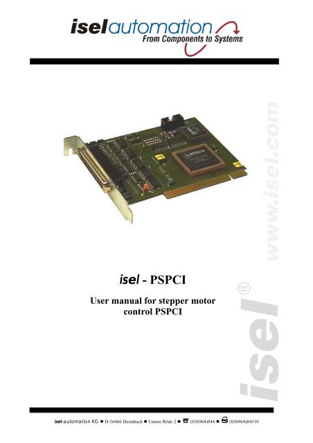
<strong>isel</strong> - <strong>PSPCI</strong><br />
User manual for stepper motor<br />
control <strong>PSPCI</strong><br />
<strong>isel</strong>-automation KG • D-36466 Dermbach • Untere Röde 2 • (036964)844 • (036964)84510
About this manual:<br />
The information, technical data and dimensions contained in this print have been up-to-date when<br />
published. Any eventually existing misprints and mistakes cannot be excluded however. We are<br />
thankful for any suggestion for improvement and indication of mistakes.<br />
Please note that the used software- and hardware descriptions of each individual company are<br />
generally subject to protection of trademarks and patent law.<br />
All rights reserved. It is not permitted to reproduce or electronically process, duplicate or spread<br />
any part of our prints in any way (print, copy etc.) without written permission of <strong>isel</strong>-automation.<br />
Producer:<br />
<strong>isel</strong>automation KG<br />
Bürgermeister-Ebert-Straße 40<br />
D-36124 Eichenzell<br />
Tel.: (06659) 981-0<br />
Fax: (06659) 981-776<br />
email: automation@<strong>isel</strong>.com<br />
http://www.<strong>isel</strong>.com<br />
In cooperation with TRIMETA Software GmbH.<br />
Art.-Nr. 970326 BE852 10/2005
Contents<br />
1 Introduction ....................................................................................................................... 1<br />
1.1 Preamble..................................................................................................................... 1<br />
2 Description of stepper motor PCI-card <strong>PSPCI</strong>............................................................... 2<br />
2.1 System requirements .................................................................................................. 2<br />
2.2 Assembly of control board in personal computer ...................................................... 2<br />
3 Installation of drivers ........................................................................................................ 2<br />
3.1 Technical Data............................................................................................................ 3<br />
3.2 Connecting control board to power electronics.......................................................... 3<br />
3 Initiation of machines with the adjusting software MtConfig....................................... 4<br />
3.1 Introduction ................................................................................................................4<br />
3.2 Starting the adjusting program ................................................................................... 4<br />
3.3 The windows of MtConfig ......................................................................................... 5<br />
3.3.1 The Main Window 5<br />
3.3.2 The Toolbar 5<br />
3.3.3 Select Parameters 6<br />
3.3.4 Save and Close 6<br />
3.3.5 The Coordinate Window 6<br />
3.3.6 Inputs/Outputs 7<br />
3.3.7 The Editor 7<br />
3.3.8 Error-Status 7<br />
3.4 Notes........................................................................................................................... 8<br />
3.4.1 Referencing 8<br />
3.4.2 Manual Jogging 8<br />
3.5 Adjusting Parameters ................................................................................................. 9<br />
3.5.1 Driver Parameters 9<br />
3.5.1.1 Addresses ....................................................................................................... 9<br />
3.5.1.2 Timer .............................................................................................................. 9<br />
3.5.1.3 Current settings ............................................................................................ 10<br />
3.5.1.4 Units ............................................................................................................. 11<br />
3.5.1.5 Axes.............................................................................................................. 11<br />
3.5.1.6 Range Limits ................................................................................................ 13<br />
3.5.1.7 Manual Moving............................................................................................ 13<br />
3.5.2 Mtasc-Parameters 14<br />
3.5.2.1 Feed Rate / Ramps........................................................................................ 14
3.5.2.2 Referencing .................................................................................................. 14<br />
3.5.2.3 Inputs and Outputs ....................................................................................... 15<br />
3.5.2.4 Extended Inputs / Outputs............................................................................ 19<br />
3.5.2.5 I/O- Actions.................................................................................................. 23<br />
3.6 Configuration of axis direction ................................................................................ 24<br />
3.6.1 Starting point 25<br />
3.6.2 Adjusting the axis- and reference directions of gantry units 26<br />
3.6.2.1 X-Axis .......................................................................................................... 26<br />
3.6.2.2 Y-Axis .......................................................................................................... 28<br />
3.6.2.3 Z-Axis........................................................................................................... 30<br />
3.6.3 Adjusting the axis- and reference direction of flatbed units 32<br />
3.6.3.1 X-Axis .......................................................................................................... 32<br />
3.6.3.2 Y-Axis .......................................................................................................... 32<br />
3.6.3.3 Z-Axis........................................................................................................... 33<br />
3.7 Optimising................................................................................................................ 34<br />
3.7.1 Procedure 34<br />
3.7.2 Further details for the optimisation 35<br />
3.7.3 The monitor window 36
<strong>isel</strong>-<strong>PSPCI</strong> User Manual<br />
1 Introduction<br />
1.1 Preamble<br />
<strong>isel</strong>automation has been known for many years for its driving systems and CNC controls with<br />
stepper motors. Stepper motors have become globally accepted in the small and medium<br />
performance range.<br />
They have practically become irreplaceable for driving systems with medium precision and<br />
dynamic requirements. Stepper motor controls usually do not work with closed loops, so<br />
expensive sensor- and evaluation units become dispensable. The result is a favourable costperformance<br />
ratio among an easy assembly and initiation.<br />
For many years we have been offering systems basing on stepper motor controls, which have<br />
been applied in many areas of production, automation, research and training.<br />
The control <strong>PSPCI</strong> has been developed to continue this product line. It is a stepper motor<br />
control, which was implemented as PCI plug-in card for PCs. It is possible to control up to 5<br />
axes with the help of clock and direction signals.<br />
This manual is to serve as support for initiating the control or machine and explain the most<br />
important parameters and adjustments.<br />
page - 1
<strong>isel</strong>-<strong>PSPCI</strong> User Manual<br />
2 Description of stepper motor PCI-card <strong>PSPCI</strong><br />
2.1 System requirements<br />
Supported System Software<br />
- Microsoft Win 2000 Pro, WinXP Home/Pro SP2<br />
Minimum hardware- requirements of control computer<br />
CPU<br />
Pentium 4 or AMD at least 1GHz<br />
RAM<br />
128MB RAM<br />
Graphic/Monitor Graphics card with resolution 800 x 600 Pixel<br />
Recommended hardware- requirements of control computer<br />
CPU<br />
Pentium 4 or AMD ≥ 1,5GHz<br />
RAM<br />
≥ 256 MB RAM<br />
Graphic/Monitor 3D Graphics card with resolution 1024 x 768 Pixel or more<br />
2.2 Assembly of control board in personal computer<br />
For the assembly of the PCI-card <strong>PSPCI</strong> please follow the following steps:<br />
1 Make sure there is one PCI slot unoccupied on your main board.<br />
2 Remove the PC Casing to be able to reach the fixing screws for the PCI slot plates.<br />
3 Now look for an unoccupied PCI bus slot.<br />
4 Remove the according slot plate of the PCI slot.<br />
5 Now plug the <strong>PSPCI</strong> stepper motor control into the slot. Make sure the card was plugged<br />
in correctly!<br />
6 Fix the card with screws.<br />
7 Close the casing of your PC.<br />
3 Installation of drivers<br />
The PCI card <strong>PSPCI</strong> will automatically be identified when booting Windows for the first time<br />
after the successful assembly of the card. The hardware installation assistant opens up. You<br />
will be asked to name the data carrier or the path, where the driver can be found. You will<br />
find the necessary driver on the ProNC/Remote installation- CD-Rom. Put a check mark to<br />
the option CD-Rom. Click on Next. The assistant will now automatically search for the driver<br />
on the CD-Rom and install it. Should the according driver not be found, you can search it<br />
yourself with the help of Windows hardware manager on the CD-Rom.<br />
page - 2
<strong>isel</strong>-<strong>PSPCI</strong> User Manual<br />
3.1 Technical Data<br />
Control specific data<br />
Number of axes 5<br />
Inputs 5<br />
Outputs 5<br />
Spindle Relais 230V Yes<br />
Analog output 0...V Yes<br />
I/O-extension Yes, 8 more inputs and 8 more outputs through I 2 C-Bus<br />
3.2 Connecting control board to power electronics<br />
A 37pole 1:1 cable is used as connecting cable between stepper motor control card <strong>PSPCI</strong> and<br />
performance electronics. Connect the SubD37 plug with the SubD37 socket of the PCI card.<br />
Connect the other end of this cable with the SubD37 socket to the designated plug on the<br />
circuit board for the output stages.<br />
Pin Signal Pin Signal<br />
1 Pulse X 20 Pulse Y<br />
2 Pulse Z 21 Pulse A<br />
3 Pulse B 22 Direction X<br />
4 Direction Y 23 Direction Z<br />
5 Direction A 24 Direction B<br />
6 +24VDC 25 +12VDC<br />
7 User output 1 26 User output 2<br />
8 User output 3 27 Output Spindle Start<br />
9 Output Enable output stages 28 --------------------------------<br />
10 GND 24V 29 positive limit switch A<br />
11 Reference switch /negative limit switch A 30 positive limit switch Z<br />
12 Reference switch /negative limit switch Z 31 positive limit switch Y<br />
13 Reference switch /negative limit switch Y 32 positive limit switch X<br />
14 Reference switch /negative limit switch X 33 positive limit switch B<br />
15 Reference switch B 34 Analogue output 0...10V<br />
16 Analogue GND 35 Input Stop button<br />
17 Input Power_ok 36 User input 1<br />
18 User input 2 37 GND 24V<br />
19 Input Start button<br />
page - 3
<strong>isel</strong>-<strong>PSPCI</strong> User Manual<br />
3 Initiation of machines with the adjusting software MtConfig<br />
3.1 Introduction<br />
MtConfig is a program to configure CNC-machines, which are navigated through Mtasc. The<br />
program does not depend on any buttons or objects visible on the screen. It configures the<br />
setting of machine and start parameters, especially for EdiTasc, ProNc and Remoteapplications.<br />
From the main-window of MtConfig you have the following options<br />
• Configure your driver settings of the Mtdrv.ini file<br />
• Configure the startup-variables for Mtasc.dll files stored in the Mtasc.ini file.<br />
• Optimize and check the parameters of a running machine.<br />
While working with MtConfig you can<br />
• display the current coordinates.<br />
• reference the axes.<br />
• display Inputs and Outputs.<br />
• issue motion commands from the editor and display values.<br />
perform manual jogging with your keyboard.<br />
Notice when using MtConfig:<br />
• Start MtConfig only out of a folder which contains the configuration-files and<br />
MTasc.dll.<br />
• MtConfig uses MTasc. Never start MtConfig if any running program uses Mtasc.<br />
3.2 Starting the adjusting program<br />
To start the adjusting program MtConfig.exe, you have to click on the shortcut in the<br />
startmenu after successfully installing and rebooting the computer.<br />
Start Programs MtConfig <strong>PSPCI</strong> MtConfig <strong>PSPCI</strong><br />
You can also start the adjusting program with the shortcut MtConfig <strong>PSPCI</strong> on your desktop.<br />
Seite - 4
<strong>isel</strong>-<strong>PSPCI</strong> User Manual<br />
3.3 The windows of MtConfig<br />
3.3.1 The Main Window<br />
The main window shows on the left<br />
• at the top the toolbar along with driver information<br />
• in the middle the list for choosing parameters and the Input pane for parameters<br />
• at the bottom buttons for referencing and for saving your settings and closing the<br />
program<br />
On the right side you will find helpful information related to the parameter or button selected.<br />
3.3.2 The Toolbar<br />
The toolbar shows the following buttons (from left to right):<br />
• referencing of the axis<br />
• enable/disable watching of the range limits<br />
• Stop motion (F9)<br />
• display coordinates<br />
• display inputs and outputs<br />
• open the editor<br />
The text field to the right contains driver information, the version of both the driver and the<br />
MTasc.dll file.<br />
Seite - 5
<strong>isel</strong>-<strong>PSPCI</strong> User Manual<br />
3.3.3 Select Parameters<br />
You can choose between parameters of the<br />
driver (Mtdrv.ini) and the MTasc-parameter<br />
(MTasc.ini).<br />
3.3.4 Save and Close<br />
If you press "Save" all changes will overwrite the original settings. It is not possible to get the<br />
original settings back after the new settings have been saved.<br />
By pressing the "Close"-button MtConfig will be closed. You will be prompted for saving the<br />
changes if there are any.<br />
3.3.5 The Coordinate Window<br />
The coordinate window shows the current coordinates of the machine. Mtasc is able to<br />
manage several coordinate systems ("object coordinates"), which are based on a fixed system<br />
of machine coordinates.<br />
If you press Shift+F1 to Shift+F7 you can change between the following displays:<br />
Shift+F1: Display Off<br />
Shift+F2: Object Coordinates<br />
Shift+F3: Machine Coordinates<br />
Shift+F4: Speed<br />
Shift+F5: Increments (Target)<br />
Shift+F6: Increments (Actual)<br />
Shift+F7: Trailing Offset (Incr.)<br />
The shown speed is a digital size.<br />
Seite - 6
<strong>isel</strong>-<strong>PSPCI</strong> User Manual<br />
3.3.6 Inputs/Outputs<br />
This window shows the state of all Inputs and<br />
Outputs defined by the descriptors _InpDsc (inputs)<br />
and _OutDsc (outputs).<br />
The number of Input/Output lines may be changed<br />
with the "+" and "-" buttons respectively. More lines<br />
can be shown using the scrollbar.<br />
The button "Refresh continuously" switches the<br />
continuous updating of the values on or off.<br />
3.3.7 The Editor<br />
The editor is used to send commands to the MTascinterpreter.<br />
This makes it possible to test moving<br />
instructions and to display or change the parameter<br />
settings of the machine.<br />
If you press Strg+Enter the following part of the<br />
input will be executed:<br />
• the highlighted text, if there is any.<br />
• the line where the keyboard cursor is located<br />
if there is no highlighted text.<br />
The example on the right shows the input "? AxisLetters;" which is not highlighted.<br />
Strg+Enter will therefore execute the whole line and show the result - XYZ - on the bottom of<br />
the Editor.<br />
3.3.8 Error-Status<br />
If an errors occurs which is related to one axis the error<br />
status will be displayed in a separate window.<br />
The error-type will be shown along with the axis on<br />
which the error occurred.<br />
In the example the machine moved too far in negative x-<br />
direction. In this case the machine will have to be moved<br />
manually in positive x-direction. It might be necessary to<br />
reset the machine by pressing F9.<br />
Seite - 7
<strong>isel</strong>-<strong>PSPCI</strong> User Manual<br />
Error<br />
Range limit<br />
Limit switch<br />
Following error<br />
TimeOut<br />
Description<br />
The machine has moved beyond the range limit. More details<br />
see MTASC-Function MLIMIT in MTasc help file).<br />
The machine has moved into a hardware limit switch in one<br />
or more axis. The corrosponding hardware limit switch (+,-)<br />
will be shown in the list.<br />
The difference between desired and current position of at least<br />
one axis has exceeded some internal limit.<br />
Depends on the type of the controller. Only when<br />
communicating with intelligent circuit boards.<br />
In these cases the machine will stop immediately.<br />
Error while using Programs (for Ex. Syntax error) will be shown in a separate window<br />
along with name and path of the file and the line in which the error occurred.<br />
3.4 Notes<br />
3.4.1 Referencing<br />
When referencing the axes (in order Z, X, Y, A, B ) will be moved towards one end to find<br />
the appropriate zero position.<br />
Before referencing the following values have to be assigned:<br />
• The output addresses for the axes<br />
• The moving direction of the axes (axes)<br />
• The direction used to reference (reference run)<br />
• The functionality of the reference switch<br />
To check if the settings are correct use manual jogging.<br />
3.4.2 Manual Jogging<br />
To move the machine manually use the keyboard combinations Strg+Alt+Arrow or<br />
AltGr+Arrow:<br />
Alt + Ctrl + right arrow:<br />
Alt + Ctrl + left arrow:<br />
Alt + Ctrl + up arrow:<br />
Alt + Ctrl + down arrow:<br />
Alt + Ctrl + page up:<br />
Alt + Ctrl + page down:<br />
Alt + Ctrl + Pos1:<br />
Alt + Ctrl + End:<br />
Alt + Ctrl + Ins:<br />
Alt + Ctrl + Del:<br />
X- axis right<br />
X- axis left<br />
Y- axis backward<br />
Y- axis forward<br />
Z- axis up<br />
Z- axis down<br />
A- axis plus<br />
A- axis minus<br />
B- axis plus<br />
B- axis minus<br />
Seite - 8
<strong>isel</strong>-<strong>PSPCI</strong> User Manual<br />
3.5 Adjusting Parameters<br />
For the adjustment of parameters, there is a destinction between driver-parameters and<br />
Mtasc parameters. These parameters will be explained in the following subchapters.<br />
3.5.1 Driver Parameters<br />
3.5.1.1 Addresses<br />
The address-pane offers for each axis a field to insert a<br />
"Data-output" address and to get a "Data-feedback". Not<br />
each PC-card supports data feedback.<br />
There should be “0000“ in every field.<br />
3.5.1.2 Timer<br />
The control cycle frequency indicates how<br />
often the real-time loop is called per second. At<br />
the same rate the position of the machine is<br />
calculated.<br />
The background frequency is used for example<br />
to configure the cycle speed of the stepper<br />
motors. The frequency must be much higher<br />
than the control cycle frequency. If a driver is in use which does not need a background<br />
frequency, enter 0.<br />
"Delay" inserts extreme short delays into the background loop. The number entered in this<br />
field is a loop counter, the generated delay depends on the hardware.<br />
The pre-adjusted value for the cycle frequency is 1000 Hz, the value for the base<br />
frequency is 100000 Hz using a step precision of a tenth step. These values should<br />
not be changed.<br />
Seite - 9
<strong>isel</strong>-<strong>PSPCI</strong> User Manual<br />
Speed limits<br />
Speed limits limit the<br />
requests which are sent to<br />
the driver by MTasc.<br />
When a request exceeds<br />
the limit, the request will<br />
be decreased accordingly.<br />
If watching of following<br />
errors is enabled all axes<br />
will be stopped when the<br />
should/is-difference is<br />
reached by at least one axis. If an axis is blocked, the other axes only move with disabled<br />
should/is-difference supervision.<br />
The first input (X-axis) of maximum acceleration takes affect on all further axis. Other<br />
inputs for residual axis will be ignored!<br />
The values in the figure can be used for machines with ball screw spindles (pitch 4, 5, 10<br />
mm).<br />
For belt drive slides (e. g. perimeter of belt pulley is 70mm and gear 2:1) speed values of<br />
800 mm/sec and accelerations of 2000-3000 mm/sec 2 can be put in here.<br />
The pre-adjusted value for “Actuate Trailing Error “ is 12100. The value for “Speed“ is<br />
12000. The value for “Speed Jump“ is 4000.<br />
These values should not be changed in any case!<br />
3.5.1.3 Current settings<br />
These adjustments are not of interest for this control board. They are only mentioned for the<br />
sake of completeness.<br />
Seite - 10
<strong>isel</strong>-<strong>PSPCI</strong> User Manual<br />
3.5.1.4 Units<br />
Here you can configure the units in which the<br />
speed and acceleration will be measured in.<br />
There are predefined unit pairs such as "mm and<br />
seconds", "cm and seconds" and "m and minutes".<br />
You can also define your own unit by pressing<br />
"user defined".<br />
The figure on the right shows the standard<br />
adjustment of area boundaries after the installation<br />
of the driver software.<br />
Enter the travel areas of the according axis into the according fields. You can either<br />
experimentally ascertain the values by manual operation or use the traverse paths of the<br />
data sheet, enclosed to the machine.<br />
3.5.1.5 Axes<br />
Here you can select the number of axes you want to use.<br />
For each axis you indicate<br />
• The axis letter<br />
• Whether the axis is enabled or not.<br />
• Alignment. The leading sign of "Move" indicates, in which direction the axis is to move<br />
with increasing increments. These leading signs should be adjusted thusly that each axis<br />
moves in manual jogging in the direction, you expect due to the keyboard-input<br />
• The type of the axis; L/R: linear- or rotary axis<br />
• Calibration. Indicate the distance one axis moves per increment. You can put in this value<br />
directly or click on "Formula". You will then see an input window, in which you have the<br />
opportunity to put in axis parameters.<br />
• The reversal clearance correction is the number of increments, that has to be added to the<br />
calculated reference value so the axis is on the expected position. To ascertain the reversal<br />
clearance correction put in the value 0 and let the axis alternately go in both directions for<br />
x increments. The value, at which the axis does not yet move, is the double reversal<br />
clearance correction<br />
• The number of axes.<br />
By clicking on the button „Calc“ of the individual axis, you see a window in which you can<br />
configure the axis. There is a distinction between linear- and rotary axes.<br />
Seite - 11
<strong>isel</strong>-<strong>PSPCI</strong> User Manual<br />
Linear axes<br />
You have to indicate the following parameters:<br />
• pitch. You can find it on the enclosed data sheet or the label plate of the machine.<br />
• steps per revolution. This value indicates the number of steps per revolution of the stepper<br />
motor. The most common stepper motors make 200 full steps per revolution and have a<br />
step angle of 1,8°.<br />
• The factor for the resolution in increments/ full steps complies with the adjustment of the<br />
step resolution of the used output stage. This factor can be changed by using the pulldown<br />
menu. The standard adjustment is tenth step. Keep this adjustment!<br />
• Transmission or reduction ratio. These values have to be indicated if a gear is used. The<br />
transmission/ reduction ratio is indicated through:<br />
revolutions / output end (roe) : revolutions / motor end (rme)<br />
Confirm the adjustments with “OK“.<br />
Rotary-/Tilting axes<br />
You have to indicate the following parameters:<br />
• pitch. For tilting axes the adjustment value has to be 360°.<br />
• steps per revolution. This value indicates the number of steps per revolution of the stepper<br />
motor. The most common stepper motors make 200 full steps per revolution and have a<br />
step angle of 1,8°.<br />
• The factor for the resolution in increments/ full steps complies with the adjustment of the<br />
step resolution of the used output stage. This factor can be changed by using the pulldown<br />
menu. The standard adjustment is tenth step. Keep this adjustment!<br />
• Transmission or reduction ratio. These values have to be indicated if a gear is used. The<br />
transmission/ reduction ratio is indicated through:<br />
revolutions / output end (roe) : revolutions / motor end (rme)<br />
Confirm the adjustments with “OK“.<br />
Seite - 12
<strong>isel</strong>-<strong>PSPCI</strong> User Manual<br />
3.5.1.6 Range Limits<br />
The range limits define the space in which<br />
the machine is allowed to move. All values<br />
have to be machine coordinates.<br />
By pressing "Set" the current position of the<br />
machine will be used as range limit.<br />
The supervision of the range limit will be<br />
deactivated while referencing. It is possible to activate/ deactivate it for each individual axis<br />
by mark the check boxes on the right.<br />
If the range limit watching is activated and the machine crosses the border it will stop moving<br />
immediately and report the error in the error-status window. The machine has to be moved in<br />
a permitted area to continue.<br />
3.5.1.7 Manual Moving<br />
On this pane you can set up all needed<br />
values for manual moving.<br />
"minimum distance" describes the distance<br />
the axis will move by pressing a key once.<br />
"V max" sets the maximum speed the axis<br />
should be able to reach.<br />
If you press a key more than once in a short time, the speed will increase in 20 steps until it<br />
reaches V max.<br />
Seite - 13
<strong>isel</strong>-<strong>PSPCI</strong> User Manual<br />
3.5.2 Mtasc-Parameters<br />
3.5.2.1 Feed Rate / Ramps<br />
On this pane you can set the speed and<br />
acceleration which will be loaded when the<br />
program starts.<br />
The values can be changed, if needed, while<br />
MTasc is running through programs or<br />
MTasc-commands.<br />
The "Angle tolerance" indicates until which angle the machine should work as if it were a<br />
straight line. That means that until this angle no ramps will be calculated.<br />
3.5.2.2 Referencing<br />
On this pane you indicate the number of axes.<br />
For each axis you have to indicate:<br />
• The axis label.<br />
• The direction of referencing.<br />
• The distance between the referencing point and the „zero point“ of the axis.<br />
• Whether referencing takes place or not.<br />
• The number of the input for the reference switch.<br />
• The referencing speed. “fast” is the speed to approach the reference switch. With<br />
“slow” the axis is moved off the switch while referencing takes place.<br />
For all axes you can select<br />
• The sequence of the axes in which referencing takes place. To change this sequence,<br />
highlight one of the axis letters and move it with the arrow keys to the right or to the<br />
left.<br />
The „Test“-button start the referencing for one axis.<br />
Seite - 14
<strong>isel</strong>-<strong>PSPCI</strong> User Manual<br />
3.5.2.3 Inputs and Outputs<br />
Fixed predefined inputs and outputs can be configured in this frame. In each case one byte<br />
will be addressed. Please enter the hexadecimal offset of the basis-address in the addressfield.<br />
The mask allows the selection of the bits which should be used for input and if they should be<br />
inverted (-) or not (+). Click on the space above the diode to change the bits.<br />
The inputs will only be read if ">" is selected. Each change of the output state will be written<br />
immediately to the corresponding address. The gained values can be re-imported through<br />
appropriate outputs by selecting ">".<br />
The LED shows the status of the bits read:<br />
• Deselected: grey<br />
• Input bit "1": red<br />
• Input bit "0": blue<br />
• Non inverted bits ("+") are shown normally.<br />
• Inverted bits ("-") are shown in an inverted mode.<br />
• Deselected bits (" ") are shown with shadowed colours.<br />
Inputs<br />
The PCI card inputs are already<br />
pre-adjusted. The inputs no. 1 –<br />
10 serve the evaluation of the<br />
hardware limit switches.<br />
The classification of the<br />
limit switches must not<br />
be changed!<br />
Seite - 15
<strong>isel</strong>-<strong>PSPCI</strong> User Manual<br />
The inputs no. 11-14 are user<br />
inputs. Using these inputs it is<br />
possible to connect peripheral<br />
devices, e. g. length callipers,<br />
pressure monitors etc. to the<br />
circuit board.<br />
These user inputs have already<br />
been pre-configured for certain<br />
peripheral devices. Depending<br />
on the machine type the<br />
according inputs are either<br />
assigned or not.<br />
Standard Assignment:<br />
No. 11 ... Start button of operating unit<br />
No. 12 ... Stop button of operating unit.<br />
No. 13 ... Length calliper (LMT) for tool monitor<br />
No. 14 ... Port 2 – free user input<br />
Before connecting new peripheral devices, please check whether the according input isn’t<br />
already assigned.<br />
Input No. 15 serves as Power_ok signal of the safety circuit module. It should not be changed<br />
under any circumstances because it is being scanned periodically by the control to evaluate a<br />
case of Emergency Stop. If there is no safety circuit module used, this input has to be<br />
connected with +24VDC.<br />
The indicated mode MMAP of inputs no. 1-15 is the so-called Memory-MAP mode. This<br />
means that the inputs are not read directly through the hardware but through the two MAP<br />
ports. Within these MAP ports the accordingly set “-“ above the LED affects the bit which is<br />
to be switched.<br />
Ports no. 17 and 18 are the so-called Memory- MAP ports. They each define an 8-bit port<br />
with the physical addresses 0x30h and 0x40h.<br />
The indicated mode PTI1 is the device type for the <strong>PSPCI</strong> card. You can find the description<br />
of the assignment of the inputs with MMAP mode to the Memory-Map ports on tab I/O –<br />
activities.<br />
Seite - 16
<strong>isel</strong>-<strong>PSPCI</strong> User Manual<br />
The following chart shows the standard configuration of the inputs with information about<br />
port numbers, addresses and bit numbers.<br />
Map-<br />
Port<br />
Input- Type Address Bit-Mask Bit-No. Function<br />
no.<br />
1 MMAP Virtual 0x01 0 Limit switch X -<br />
2 MMAP Virtual 0x02 1 Limit switch X +<br />
3 MMAP Virtual 0x04 2 Limit switch Y -<br />
4 MMAP Virtual 0x08 3 Limit switch Y+<br />
0<br />
5 MMAP Virtual 0x10 4 Limit switch Z -<br />
6 MMAP Virtual 0x20 5 Limit switch Z +<br />
7 MMAP Virtual 0x40 6 Limit switch A -<br />
8 MMAP Virtual 0x80 7 Limit switch A +<br />
9 MMAP Virtual 0x40 8 Limit switch B -<br />
10 MMAP Virtual 0x80 9 Limit switch B +<br />
11 MMAP Virtual 0x02 10 Input Start button<br />
12 MMAP Virtual 0x04 11 Input Stop button<br />
1<br />
13 MMAP Virtual 0x08 12 Length caliper<br />
14 MMAP Virtual 0x10 13 User input 2<br />
15 MMAP Virtual 0x02 14 Input Power_ok<br />
16 MMAP Virtual 0x01 15 Unemployable !<br />
17 PTI1 0x0030 0xFF 0 - 7 Map-Port 0<br />
18 PTI1 0x0040 0xFF 8 - 16 Map-Port 1<br />
Changes should only be made regarding the description of the user inputs.<br />
Changes of addresses and bits can result a faultily behaviour of the control.<br />
Seite - 17
<strong>isel</strong>-<strong>PSPCI</strong> User Manual<br />
Outputs<br />
The outputs of the PCI card are<br />
already pre-adjusted. Outputs<br />
no. 1 – 3 are user outputs.<br />
Using these outputs it is<br />
possible to connect peripheral<br />
devices, e. g. tool changers,<br />
cooling / spraying systems,<br />
magnetic switches etc. to the<br />
circuit board.<br />
Output no. 4 operates a 230V<br />
relay on the circuit board for<br />
the drive spindle.<br />
Standard assignment of user outputs:<br />
No. 1 ... Collet – operating output to open/close the collet of the working spindle.<br />
No. 2 ... Tool changer hood – open/close hood of tool changer.<br />
No. 3 ... Cooling – operating output for cooling/ spraying or cooling system.<br />
No. 4 ... Spindle – operating output for turning on/ off a working spindle.<br />
Output no. 5 and 6 are automatically set by the PCI- card. They serve to release the brake of<br />
the axes (if existing) and to “Enable” the power of the amplifiers.<br />
Output no. 9 is a virtual output, which used by the Mtasc driver. It serves the controlled<br />
operation of the physical outputs Nor. 5, 6.<br />
The following chart shows the standard configuration of the outputs with information about<br />
port numbers, addresses and bit numbers.<br />
No. Type Address Bit-Mask Inv. Bit-Mask Function<br />
1 PTI1 0020h 0x01 0x00 Collet open/close<br />
2 PTI1 0020h 0x02 0x00 Workpiece clamp. dev. open/close<br />
3 PTI1 0020h 0x04 0x00 Cooling on/off<br />
4 PTI1 0020h 0x08 0x00 Output Spindle Start<br />
5 PTI1 0020h 0x10 0x00 Output Enable output stages<br />
6 PTI1 0020h 0x20 0x00 Output Brakes<br />
7 PTI1 0060h 0xFF 0x00 Analogue output 0..10V (Port)<br />
8 PTI1 0020h ------------------- ---- Unemployable<br />
9 PTI1 0020h ------------------- ---- _MotOn/Off (virtual output)<br />
Changes should only be made regarding the description of the user ouputs.<br />
Changes of addresses and bits can result faultily behaviour of the control.<br />
Seite - 18
<strong>isel</strong>-<strong>PSPCI</strong> User Manual<br />
3.5.2.4 Extended Inputs / Outputs<br />
Extended Inputs<br />
The expanded inputs serve the transfer of the inputs<br />
(no. 1 – 16), adjusted in MtConfig to ProNC/<br />
Remote. Eight inputs comply here with an extended<br />
input (input port). The following information has to<br />
be indicated:<br />
• Type. Here has to be indicated PTI1 as type of control. This can be chosen by clicking<br />
on the input field.<br />
• Address of ports. The address is the same as the one of the complying Map port. (see<br />
chart in chapter inputs.).<br />
• With the mask you can indicate which bits will be used for the input and whether the<br />
bits should be inverted (-) or not (+). The inputs will only be read if ">" is activated.<br />
Each change of the initial state is immediately written to the complying address.<br />
• The number of expanded inputs can be chosen between 0 and 6 and is saved in the file<br />
Mtasc.ini under the key "n=". If "n=-1" is written in the according section of<br />
Mtasc.ini, the expanded inputs are not displayed.<br />
The light emitting diodes indicate the condition of the imported bit string.<br />
• Not imported: grey<br />
• Input "1": red<br />
• Input "0": blue<br />
• Directly imported bits ("+") are displayed normally.<br />
• Inverted bits ("-") are displayed inverted.<br />
• Faded out bits (" ") are displayed as un-logged.<br />
The following chart shows the pre-adjusted configuration of the expanded inputs.<br />
Port No. 1 with address 0030h, Map-Port 0 (Map0) with device type PTI<br />
Bit / Addr. Application Logical Port Plug SubD-37-Pin<br />
1 / 0x01h Limit switch X -<br />
I1.1<br />
14<br />
2 / 0x02h Limit switch X +<br />
I1.2<br />
32<br />
3 / 0x04h Limit switch Y -<br />
I1.3<br />
13<br />
4 / 0x08h Limit switch Y +<br />
I1.4<br />
31<br />
5 / 0x10h Limit switch Z -<br />
I1.5<br />
12<br />
6 / 0x20h Limit switch Z +<br />
I1.6<br />
30<br />
7 / 0x40h Limit switch A -<br />
I1.7<br />
11<br />
8 / 0x80h Limit switch A +<br />
I1.8<br />
29<br />
Seite - 19
<strong>isel</strong>-<strong>PSPCI</strong> User Manual<br />
Port No. 2 with address 0040h, Map-Port 1 (Map1) with device type PTI1<br />
Bit/Addr. Application Logical Port Plug SubD-37<br />
Pin<br />
1 / 0x01h Unemployable! --------------------------- --- --<br />
2 / 0x02h Input Start button<br />
3 / 0x04h Input Stop button<br />
4 / 0x08h Length measureing caliper<br />
5 / 0x10h User input 2 – unoccupied<br />
6 / 0x20h Input Power_ok<br />
7 / 0x40h Limit switch B -<br />
8 / 0x80h Limit switch B +<br />
I2.2<br />
I2.3<br />
I2.4<br />
I2.5<br />
I2.6<br />
I2.7<br />
I2.8<br />
X34 19<br />
X21 35<br />
X27 36<br />
X28 18<br />
X29 17<br />
--- 15<br />
--- 33<br />
Mask of both ports<br />
Port No. Type Address Bit-Mask Map-Port<br />
1 PTI1 0030h 0xFF 0 (Map0)<br />
2 PTI1 0040h 0xFE 1 (Map1)<br />
The masks of these two expanded inputs serve the signalling of the conditions in ProNC/<br />
Remote. These two extended inputs are displayed as two super-imposed bit strings within the<br />
I/O direct access window. Only those inputs are displayed correctly which have been marked<br />
(provided with + or -) with the mask of the extended input.<br />
Changes should not be made here!<br />
Seite - 20
<strong>isel</strong>-<strong>PSPCI</strong> User Manual<br />
Extended Output<br />
The extended outputs serve the transfer of the outputs, adjusted in MtConfig, to ProNC/<br />
Remote. Eight outputs comply here with an extended output (output port).<br />
The following information has to be<br />
indicated:<br />
• Type. Here has to be indicated PTI1<br />
as type of control. This can be<br />
chosen by clicking on the input field.<br />
• Address of ports. The address is the same as the one of the complying Map port. (see<br />
chart in chapter inputs.).<br />
• With the mask you can indicate which bits will be used for the input and whether the<br />
bits should be inverted (-) or not (+). The inputs will only be read if ">" is activated.<br />
Each change of the initial state is immediately written to the complying address.<br />
• The number of extended inputs can be chosen between 0 and 6 and is saved in the file<br />
Mtasc.ini under the key "n=". If "n=-1" is written in the according section of<br />
Mtasc.ini, the extended inputs are not displayed.<br />
The light emitting diodes indicate the condition of the imported bit string.<br />
• Not imported: grey<br />
• Input "1": red<br />
• Input "0": blue<br />
• Directly imported bits ("+") are displayed normally.<br />
• Inverted bits ("-") are displayed inverted.<br />
• Faded out bits (" ") are displayed as un-logged.<br />
Seite - 21
<strong>isel</strong>-<strong>PSPCI</strong> User Manual<br />
The following chart shows the pre-adjusted configuration of the extended outputs.<br />
Port no. 1 with address 0020h, device type PTI1<br />
Bit /<br />
Addr.<br />
Application Logical Port Plug SubD-<br />
37-Pin<br />
1 / 0x01h Collet open/close<br />
O1.1<br />
Tool clamping device open/<br />
2 / 0x02h<br />
close O1.2<br />
X30 7<br />
X31 26<br />
3 / 0x04h Cooling on/off<br />
O1.3<br />
X32 8<br />
4 / 0x08h Output Spindle Start<br />
O1.4<br />
X19 27<br />
5 / 0x10h Output Enable output stage Not switchable by user! --- 9<br />
6 / 0x20h Output brake<br />
Not switchable by user!<br />
--- 28<br />
7 / 0x40h Analogue output 0..10V X20 16<br />
8 / 0x80h unemployable ---- --- --<br />
Port No. Type Address Bit-Mask Inv. Bit-Mask<br />
1 PTI1 0020h 0x0F 0x00<br />
The mask of this extended output serve the signalling of the conditions in ProNC/ Remote.<br />
The output is displayed as a bit string within the I/O direct access window. Only those binary<br />
output are displayed correctly which have been marked (provided with + or -) with the mask<br />
of the extended output.<br />
Changes should not be made here!<br />
Seite - 22
<strong>isel</strong>-<strong>PSPCI</strong> User Manual<br />
3.5.2.5 I/O- Actions<br />
Please read the following descriptions thoroughly. A change of the parameters<br />
can result in a dysfunction of the <strong>PSPCI</strong> card and thus your machine.<br />
You should not change the pre-adjusted values!!!!<br />
In I/O-activities you can define and adjust the monitoring of hardware limit switches.<br />
In other words, the assignment of the physical input addresses of the card to the „virtual”<br />
inputs, which signal the<br />
condition of the limit<br />
switch if taking place<br />
here.<br />
To every MAP-Port<br />
there is a fixed index, a<br />
start bit and a number<br />
of bits assigned. In this<br />
case the MAP ports<br />
with the physical<br />
addresses 0x30h and<br />
0x40h (no.1 Adr30,<br />
no.2 Adr.40) are defined with the input descriptors no. 17 and 18. The inputs defined on these<br />
MAP ports reflect the current condition of the physical inputs of the <strong>PSPCI</strong> card. The six<br />
check boxes serve the configuration of the cache, writing and reading direction. Only the first<br />
check box on the left is of interest. By checking the box the MAP port is activated.<br />
The entries from no. 3 to no. 12 define the actual assignment of the physical inputs to the<br />
MAP-Ports. For each limit switch (limit switch -, limit switch +) the input descriptor no.,<br />
descriptor bit no., map index, map bit no. and the number of bits to be operated have to be<br />
indicated here. The configuration has already been adjusted for five axes. You should not<br />
change the values. Only the first check box on the left with the complying entry is of interest.<br />
By deactivating the check boxes of no. 3 – 12 you can deactivate the monitoring of the<br />
hardware limit switches.<br />
In this configuration<br />
the two hardware limit<br />
switches of the y-axis<br />
are deactivated for<br />
example.<br />
Seite - 23
<strong>isel</strong>-<strong>PSPCI</strong> User Manual<br />
3.6 Configuration of axis direction<br />
In this chapter the configuration of the X-, Y- and Z axis direction will be explained. Due to<br />
the different constructions and arrangements of the axis on machines and systems, the<br />
standard adjustments for the axis direction have to be changed.<br />
As a basic principle two different types of machines have to be distinguished:<br />
‣ Gantry units ( e. g. EuroMod P Series)<br />
The machine table (Y axis) carries the clamping plate for<br />
the work piece. It moves in positive Y direction from the<br />
tool tip when moving towards the operator.<br />
‣ Flatbed units (e.g. EuroMod F Series, FlatCom<br />
Series, OverHead Series)<br />
The clamping area for the work piece is solidly fixed on the<br />
machine frame. A Y-movement of the tool in positive<br />
direction (+Y) goes away from the operator.<br />
For both types the axis direction has to be considered regarding the tool tip, so<br />
the coordinate system adds up to a „right-system“. (right-hand-rule).<br />
Seite - 24
<strong>isel</strong>-<strong>PSPCI</strong> User Manual<br />
Assignment of axis directions<br />
The assignment of the moving axes regarding the operating position is:<br />
‣ For flatbed units<br />
• X-axis = transverse axis (+X to the right; -X to the left)<br />
• Y-axis = longitudinal axis (+Y away from operator; -Y towards operator)<br />
• Z-axis = lifting axis (+Z upward; -Z downward)<br />
‣ For gantry units<br />
• X-axis = transverse axis (+X to the right; -X to the left)<br />
• Y-axis = longitudinal axis (-Y away from operator; +Y towards operator)<br />
• Z-axis = lifting axis (+Z upward; -Z downward)<br />
The procedure to initiate the axis is explained in the subchapters of each machine type.<br />
3.6.1 Starting point<br />
• Please check all adjustments of drivers and Mtasc parameters of the previous<br />
chapters.<br />
• Check if the ports on the circuit board are correctly:<br />
Are the motor cables plugged in correctly?<br />
Are the signal cables for limit switches and brake plugged in correctly?<br />
Are the signal cables of the SK module plugged in correctly?<br />
Are the inputs and outputs connected according to the standard assignment?<br />
• Check the power supply of limit switches and circuit boards:<br />
Do the LED of the output stages glow?<br />
Is the power button pushed?<br />
Please use the delivered documentation of your machine to do the inspection. (circuit<br />
diagram, manual etc.)<br />
Seite - 25
<strong>isel</strong>-<strong>PSPCI</strong> User Manual<br />
3.6.2 Adjusting the axis- and reference directions of gantry units<br />
Follow the instructions for the initiation of the individual axes.<br />
3.6.2.1 X-Axis<br />
1) Click on the button „I/O – Actions“ in MtConfig. Deactivate the hardware limit switch of<br />
the X axis by removing the check in the first check box of the left. (also see chapter:<br />
3.5.2.5 I/O- Actions)<br />
2) Now move to the field „Axes“ within the driver parameters. Check the alignment by<br />
manually moving the X axis. Therefore use the short cut Alt + Ctrl + left arrow and Alt<br />
+ Ctrl + right arrow<br />
The following picture shows the correct axis alignment.<br />
In case the X axis does not move as shown in the picture, please change the direction of<br />
the axis by pushing the button for the direction of the axis.<br />
Click the button “Save“ in the main window of MtConfig to save the new adjustments.<br />
Check the alignment again.<br />
Seite - 26
<strong>isel</strong>-<strong>PSPCI</strong> User Manual<br />
Now the referencing direction of the axis has to be adjusted. Make sure the axis is not in<br />
a limit switch position. To do this you have to go to the adjusting field “referencing”.<br />
The hardware limit switches of each axis are fixed and should not be changed by means of<br />
the configuration program.<br />
Please take a look at the window for the inputs and outputs. The first two entries are:<br />
Both limit switches are plugged in correctly if the left LED next to the entry is blue<br />
in inactive condition.<br />
3) Move the X-axis by pushing Alt + Ctrl + left arrow slowly to the left in the direction of<br />
the limit switch. -. While moving, watch the display of the inputs, in particular input no.<br />
1 limit switch X -.Now move until the blue LED for limit switch X- goes out.<br />
Should this not be the case and the LED for limit switch X+ goes out instead, you have to<br />
exchange the wiring of the signal cables for the limit switches on the circuit board. This<br />
means you have to exchange limit switch X- and X+ for the X axis.<br />
As soon as the LED for limit switch X- is out, please move to the opposite direction away<br />
from the limit switch. Now the LED has to be blue again.<br />
Repeat this step again for the other limit switch. Move the axis by pushing Alt + Ctrl +<br />
right arrow. Also check the functioning of the limit switch.<br />
4) After you have checked both hardware limit switches, you have to adjust the referencing<br />
direction. For this purpose you have to move the axis to the middle of the traverse range.<br />
Click on “Test“ all the way on the right within the entry field of the according axis. Watch<br />
the movement of the axis. If the axis moves to the left in direction of limit switch X-, the<br />
referencing direction is adjusted correctly. Now you have to check the reference input,<br />
that is to be used for referencing. In this case input no. 1 limit switch X- serves as<br />
reference switch. (see picture above)<br />
If the axis does not move in the right direction, please cancel the referencing of axis by<br />
pushing F9 or the button . Now invert the referencing direction by pushing the<br />
button . Save the adjustments.<br />
Repeat the referencing to check the adjustments again.<br />
1) If the referencing was successfully completed, save all adjustments. Activate the hardware<br />
limit switch monitoring for the axis within the entry field I/O-activities by checking the<br />
first check box. (see also chapter: 3.5.2.5 I/O- Actions). Save the adjustments again.<br />
You can now configure the next axis.<br />
Seite - 27
<strong>isel</strong>-<strong>PSPCI</strong> User Manual<br />
3.6.2.2 Y-Axis<br />
1) Click on the button „I/O – Actions“ in MtConfig. Deactivate the hardware limit switch of<br />
the Y axis by removing the check in the first check box of the left. (also see chapter:<br />
3.5.2.5 I/O- Actions)<br />
2) Now move to the field „Axes“ within the driver parameters. Check the alignment by<br />
manually moving the Y axis. For this use the short cut Alt + Ctrl + up arrow and Alt +<br />
Ctrl + down arrow.<br />
The following picture shows the correct axis alignment.<br />
In case the Y axis does not move as shown in the picture, please change the direction of<br />
the axis by pushing the button for the direction of the axis.<br />
Click the button “Save“ in the main window of MtConfig to save the new adjustments.<br />
Check the alignment again.<br />
Seite - 28
<strong>isel</strong>-<strong>PSPCI</strong> User Manual<br />
Now the referencing direction of the axis has to be adjusted. Make sure the axis is not in<br />
a limit switch position. To do this you have to go to the adjusting field “referencing”.<br />
The hardware limit switches of each axis are fixed and should not be changed by means of<br />
the configuration program.<br />
Please take a look at the window for the inputs and outputs. Entry no. 3 and 4 is:<br />
Both limit switches are plugged in correctly if the left LED next to the entry is blue<br />
in inactive condition.<br />
3) Move the Y-axis by pushing Alt + Ctrl + up arrow slowly forwardly towards you in the<br />
direction of the limit switch. -. While moving, watch the display of the inputs, in<br />
particular input no. 4 limit switch Y +.Now move until the blue LED for limit switch<br />
Y+ goes out.<br />
Should this not be the case and the LED for limit switch Y- goes out instead, you have to<br />
exchange the wiring of the signal cables for the limit switches on the circuit board. This<br />
means you have to exchange limit switch Y+ and Y- for the Y axis.<br />
As soon as the LED for limit switch Y+ is out, please move to the opposite direction away<br />
from the limit switch. Now the LED has to be blue again.<br />
Repeat this step again for the other limit switch. Move the axis by pushing Alt + Ctrl +<br />
+ down arrow. Also check the functioning of the limit switch.<br />
After you have checked both hardware limit switches, you have to adjust the referencing<br />
direction. For this purpose you have to move the axis to the middle of the traverse range.<br />
Click on “Test“ all the way on the right within the entry field of the according axis. Watch<br />
the movement of the axis. If the axis moves forwardly towards you in direction of limit<br />
switch Y+, the referencing direction is adjusted correctly. Now you have to check the<br />
reference input, that is to be used for referencing. In this case input no. 4 limit switch<br />
Y+ serves as reference switch. (see picture above)<br />
If the axis does not move in the right direction, please cancel the referencing of axis by<br />
pushing F9 or the button . Now invert the referencing direction by pushing the<br />
button . Save the adjustments.<br />
Repeat the referencing to check the adjustments again.<br />
4) If the referencing was successfully completed, save all adjustments. Activate the hardware<br />
limit switch monitoring for the axis within the entry field I/O-activities by checking the<br />
first check box. (see also chapter: 3.5.2.5 I/O- Actions). Save the adjustments again.<br />
You can now configure the next axis.<br />
Seite - 29
<strong>isel</strong>-<strong>PSPCI</strong> User Manual<br />
3.6.2.3 Z-Axis<br />
1) Click on the button „I/O – Activities“ in MtConfig. Deactivate the hardware limit switch<br />
of the Z axis by removing the check in the first check box of the left. (also see chapter:<br />
3.5.2.5 I/O- Acti)<br />
2) Now move to the field „Axes“ within the driver parameters. Check the alignment by<br />
manually moving the Z axis. For this use the short cut Alt + Ctrl + page up and Alt +<br />
Ctrl + page down<br />
The following picture shows the correct axis alignment.<br />
In case the Z axis does not move as shown in the picture, please change the direction of<br />
the axis by pushing the button for the direction of the axis.<br />
Click the button “Save“ in the main window of MtConfig to save the new adjustments.<br />
Check the alignment again.<br />
Seite - 30
<strong>isel</strong>-<strong>PSPCI</strong> User Manual<br />
Now the referencing direction of the axis has to be adjusted. Make sure the axis is not in<br />
a limit switch position. To do this you have to go to the adjusting field “referencing”.<br />
The hardware limit switches of each axis are fixed and should not be changed by means of<br />
the configuration program. Please take a look at the window for the inputs and outputs.<br />
Entry no. 5 and 6 is:<br />
Both limit switches are plugged in correctly if the left LED next to the entry is blue<br />
in inactive condition.<br />
3) Move the Z-axis by pushing Alt + Ctrl + page up slowly up in the direction of the limit<br />
switch. +. While moving, watch the display of the inputs, in particular input no. 6 limit<br />
switch Z+. Now move until the blue LED for limit switch Z+ goes out.<br />
Should this not be the case and the LED for limit switch Z- goes out instead, you have to<br />
exchange the wiring of the signal cables for the limit switches on the circuit board. This<br />
means you have to exchange limit switch Z- and Z+ for the Z axis.<br />
As soon as the LED for limit switch Z+ is out, please move to the opposite direction away<br />
from the limit switch. Now the LED has to be blue again.<br />
Repeat this step again for the other limit switch. Move the axis by pushing Alt + Ctrl +<br />
page down. Also check the functioning of the limit switch.<br />
4) After you have checked both hardware limit switches, you have to adjust the referencing<br />
direction. For this purpose you have to move the axis to the middle of the traverse range.<br />
Click on “Test“ all the way on the right within the entry field of the according axis. Watch<br />
the movement of the axis. If the axis moves up in direction of limit switch Z+, the<br />
referencing direction is adjusted correctly. Now you have to check the reference input,<br />
that is to be used for referencing. In this case input no. 6 limit switch Z+ serves as<br />
reference switch. (see picture above)<br />
If the axis does not move in the right direction, please cancel the referencing of axis by<br />
pushing F9 or the button . Now invert the referencing direction by pushing the<br />
button . Save the adjustments.<br />
Repeat the referencing to check the adjustments again.<br />
5) If the referencing was successfully completed, save all adjustments. Activate the hardware<br />
limit switch monitoring for the axis within the entry field I/O-activities by checking the<br />
first check box. (see also chapter: 3.5.2.5 I/O- Actions). Save the adjustments again.<br />
Seite - 31
<strong>isel</strong>-<strong>PSPCI</strong> User Manual<br />
3.6.3 Adjusting the axis- and reference direction of flatbed units<br />
Follow the instructions for the initiation of the individual axes.<br />
3.6.3.1 X-Axis<br />
Please read the initiating instruction of the X-axis for gantry units and follow the steps. (see<br />
chapter 3.6.2.1 X-Axis)<br />
3.6.3.2 Y-Axis<br />
1) Click on the button „I/O – Activities“ in MtConfig. Deactivate the hardware limit switch<br />
of the Y axis by removing the check in the first check box of the left. (also see chapter:<br />
3.5.2.5 I/O- Actions)<br />
2) Now move to the field „Axes“ within the driver parameters. Check the alignment by<br />
manually moving the Y axis. For this use the short cut Alt + Ctrl + up arrow and Alt +<br />
Ctrl + down arrow.<br />
The following picture shows the correct axis alignment.<br />
In case the Y axis does not move as shown in the picture, please change the direction of<br />
the axis by pushing the button for the direction of the axis. Click the button “Save“ in<br />
the main window of MtConfig to save the new adjustments. Check the alignment again.<br />
Seite - 32
<strong>isel</strong>-<strong>PSPCI</strong> User Manual<br />
Now the referencing direction of the axis has to be adjusted. Make sure the axis is not in<br />
a limit switch position. To do this you have to go to the adjusting field “referencing”.<br />
The hardware limit switches of each axis are fixed and should not be changed by means of<br />
the configuration program.<br />
Please take a look at the window for the inputs and outputs. Entry no. 3 and 4 is:<br />
Both limit switches are plugged in correctly if the left LED next to the entry is blue<br />
in inactive condition.<br />
6) Move the Y-axis by pushing Alt + Ctrl + up arrow slowly forwardly towards you in the<br />
direction of the limit switch. -. While moving, watch the display of the inputs, in<br />
particular input no. 4 limit switch Y +.Now move until the blue LED for limit switch<br />
Y+ goes out.<br />
Should this not be the case and the LED for limit switch Y- goes out instead, you have to<br />
exchange the wiring of the signal cables for the limit switches on the circuit board. This<br />
means you have to exchange limit switch Y+ and Y- for the Y axis.<br />
As soon as the LED for limit switch Y+ is out, please move to the opposite direction away<br />
from the limit switch. Now the LED has to be blue again.<br />
Repeat this step again for the other limit switch. Move the axis by pushing Alt + Ctrl +<br />
down arrow. Also check the functioning of the limit switch.<br />
After you have checked both hardware limit switches, you have to adjust the referencing<br />
direction. For this purpose you have to move the axis to the middle of the traverse range.<br />
Click on “Test“ all the way on the right within the entry field of the according axis. Watch<br />
the movement of the axis. If the axis moves forwardly towards you in direction of limit<br />
switch Y+, the referencing direction is adjusted correctly. Now you have to check the<br />
reference input, that is to be used for referencing. In this case input no. 4 limit switch<br />
Y+ serves as reference switch. (see picture above)<br />
If the axis does not move in the right direction, please cancel the referencing of axis by<br />
pushing F9 or the button . Now invert the referencing direction by pushing the<br />
button . Save the adjustments.<br />
Repeat the referencing to check the adjustments again.<br />
7) If the referencing was successfully completed, save all adjustments. Activate the hardware<br />
limit switch monitoring for the axis within the entry field I/O-activities by checking the<br />
first check box. (see also chapter: 3.5.2.5 I/O- Actions). Save the adjustments again.<br />
You can now configure the next axis.<br />
3.6.3.3 Z-Axis<br />
Please read the initiating instruction of the Z-axis for gantry units and follow the steps. (see<br />
chapter 3.6.2.1 Z-Axis)<br />
Seite - 33
<strong>isel</strong>-<strong>PSPCI</strong> User Manual<br />
3.7 Optimising<br />
Within the optimising window the parameters for the motor control are indicated and<br />
optimised.<br />
The axes can be moved separately or coupled within a given travel distance, while the<br />
parameters are being adjusted. The monitoring window always opens together with the<br />
optimising window. Within the monitoring window the track data of the moving axes are<br />
graphically displayed.<br />
3.7.1 Procedure<br />
1 Choose the axis which is to be optimised (1).<br />
2 Adjust the travel range (2).<br />
3 Move to the position which is to be the 0 position, if necessary do so by manual jogging.<br />
4 If necessary reset the current position of the machine with "=0" (3).<br />
5 Adjust the speed with the slide control. (4). The speed can also be changed while moving.<br />
6 If necessary, adjust the acceleration. (5)<br />
7 Start the movement by clicking on "MOVE" (6).<br />
8 You can change the parameters during the moving process. To do so, click into the field,<br />
whose value you want to change and enter a new value or use the slide control. (8).<br />
9 If necessary, adapt the multipliers accordingly (7).<br />
10 By clicking on "Circle" (9) (not available in automatic mode) the machine is forced to<br />
make a circle for two of the three axes X, Y and Z. You chose the axes within the column<br />
"Move".<br />
Seite - 34
<strong>isel</strong>-<strong>PSPCI</strong> User Manual<br />
11 A change of the travel range during the moving process affects later because the moving<br />
command cache (10) can still contain moving commands. Empty this cache by clicking<br />
on "RESET", this way the cache is emptied and the motor control reset.<br />
12 You save the newly adjusted values with "Save". If values have been changed, you will<br />
be asked whether the new values are to be saved when leaving the optimising window.<br />
3.7.2 Further details for the optimisation<br />
If the parameters have to be completely recalibrated, it is useful to reset the D- and I values (if<br />
available) and increase the P values until the machine runs with a „fixed“ noise without<br />
becoming loud.<br />
After that the D-controller will be raised until the target/actual deviation displayed in the<br />
monitoring window are minimal. This process can be automatically supported by clicking on<br />
„AUTO“<br />
If both values are adjusted, the I-controller (if available) can be used for fine tuning. The I<br />
value is only sensible if using a closed loop. It is usually used for axes with high mechanical<br />
friction.<br />
Seite - 35
<strong>isel</strong>-<strong>PSPCI</strong> User Manual<br />
3.7.3 The monitor window<br />
Within the monitoring window either the target/actual deviations or optionally the speeds of<br />
up to two axes are graphically displayed at the same time.<br />
The display is two coloured: Green is for movement in positive direction and red for<br />
movement in negative direction of the individual axis. If the shown values are above the<br />
horizontal line the current machine velocity is lower than the target velocity.<br />
Adaptations:<br />
1) Select the axes with the Axis selection (1).<br />
2) Change the maximum value of the scale with the scale factor (2).<br />
3) Select between bar and point display with the display selection (3).<br />
4) If you stop the display, (4), another button "Details" appears (not visible here), and a<br />
block of the upper line is marked by a case.<br />
5) The contents of this case is displayed with a tenfold resolution in the lower line. The detail<br />
block can be adapted by moving the case with the mouse.<br />
Seite - 36