ISRxx Serie Bedienungsanleitung - Bedienungsanleitungen ...
ISRxx Serie Bedienungsanleitung - Bedienungsanleitungen ...
ISRxx Serie Bedienungsanleitung - Bedienungsanleitungen ...

You also want an ePaper? Increase the reach of your titles
YUMPU automatically turns print PDFs into web optimized ePapers that Google loves.
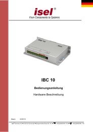
iSR series<br />
iSR 10, iSR 11, iSR 20<br />
User Manual<br />
isel Germany AG, D-36124 Eichenzell, Bürgermeister-Ebert-Str. 40 (06659)981-0 (06659)981-776
The information, technical data and dimensions contained in this print have been up-to-date<br />
when published. Any eventually existing misprints and mistakes cannot be excluded however.<br />
We are thankful for any suggestion for improvement and indication of mistakes.<br />
Please note that the used software- and hardware descriptions of each individual company are<br />
generally subject to protection of trademarks and patent law.<br />
All rights reserved. It is not permitted to reproduce or electronically process, duplicate or spread<br />
any part of our prints in any way (print, copy etc.) without written permission of isel Germany<br />
AG.<br />
Manufacturer:<br />
isel Germany AG<br />
Bürgermeister-Ebert-Straße 40<br />
D-36124 Eichenzell<br />
Tel.: (06659) 981-0<br />
Fax: (06659) 981-776<br />
Email: automation@isel.com<br />
http://www.isel.com<br />
Status:<br />
09/2009 CB
Table of contents<br />
1 Introduction ......................................................................................................................... 1<br />
1.1 Safety symbols ............................................................................................................... 1<br />
1.2 Safety instructions .......................................................................................................... 1<br />
2 Types ..................................................................................................................................... 2<br />
3 Product description ............................................................................................................. 3<br />
3.1 Technical data ................................................................................................................ 3<br />
3.2 Dimension drawings ....................................................................................................... 5<br />
3.3 Power supply and control connectors ............................................................................. 7<br />
3.3.1 Power supply and control connectors - iSR10 ...................................................................... 7<br />
3.3.2 Power supply and control connectors - iSR10 ...................................................................... 8<br />
3.3.3 Power supply and control connectors – iSR20 ..................................................................... 9<br />
4 Interfaces ............................................................................................................................ 10<br />
4.1.1 PC interfaces iSR10 ............................................................................................................ 10<br />
4.1.2 Schnittstellen - iSR11 ......................................................................................................... 11<br />
4.1.3 PC interfaces iSR20 ............................................................................................................ 14<br />
5 Mounting ............................................................................................................................ 15<br />
6 Switch on the control PC .................................................................................................. 15<br />
7 Maintenance and Cleaning ............................................................................................... 16<br />
8 EC Declaration of Conformity ......................................................................................... 17<br />
9 Bibliography ...................................................................................................................... 18
iSR series User Manual<br />
1 Introduction<br />
1.1 Safety symbols<br />
Attention<br />
This symbol signalizes that there is danger for peoples life und health.<br />
Danger<br />
This symbol signalizes that there is danger for material, machine and<br />
environment.<br />
Information<br />
This symbol signalizes important information.<br />
1.2 Safety instructions<br />
• The Control PC series iSRxx are designed to current technical and<br />
recognized rules.<br />
• The device may only be used if it is in correct condition. Any faults have to<br />
be eliminated immediately. Neither children nor non-authorized persons are<br />
allowed to put the device into operation.<br />
• The device may only be used for the intended use.<br />
• All work on the module must be executed from authorized personal<br />
regarding electrical industry rules and accident prevention regulations.<br />
• Assembly and use of operating material has to be according to the standards<br />
of conformity declaration. In case of in proper use even the observation the<br />
respective rules and standards does not protect against physical damages and<br />
damage to property.<br />
• Do not expose the device to high humidity or high vibrations.<br />
• Please take care of the instruction manual. Be sure that all users know the<br />
instructions.<br />
• Ignoring the instruction manual can lead to damage, heavy physical damage<br />
or to death.<br />
Page - 1
iSR series User Manual<br />
2 Types<br />
The CAN-PC´s iSR 10/11 are PC-based control computers on a favorable price-performanceratio.<br />
The housings are optimized for control box installation.<br />
They vary in different configuration features:<br />
Typ Form-Faktor CAN-Interface<br />
iSR10<br />
1 x PCI CAN Interface – 1 x RJ45 CAN Out<br />
Part.-No.: 371060 MiniITX<br />
iSR11<br />
Part.-No.: 371062<br />
iSR20<br />
Part.-No.: 371057<br />
MiniITX<br />
µATX<br />
1 x PCI CAN Interface – 1 x RJ45 CAN Out<br />
1 x CAN IO (16x In, 8xOut, 1x Analog Out)<br />
1 x PCI CAN Interface – 1x RJ45 CAN Out<br />
option:<br />
2 x RJ45 CAN Out, 2 Kanal CAN Out Interface<br />
Page - 2
iSR series User Manual<br />
3 Product description<br />
3.1 Technical data<br />
iSR10 iSR11 iSR20<br />
dimensions (L x H x W): 210 x 75 x 200 mm 210 x 75 x 200 mm 280 x 70 x 180 mm<br />
weight: 1,2 kg 1,4 kg 2,6 kg<br />
admissible ambient: 0°C bis 55°C<br />
humidity:<br />
max. 90% non condensable<br />
safety class:<br />
IP20<br />
power supply voltage: 12 V DC 12 V DC AC 115/230 V 60/50Hz<br />
use:<br />
desk controller / control box desk controller / control box<br />
mounting<br />
mounting<br />
control box mounting<br />
form-factor: Mini-ITX Mini-ITX µATX<br />
CPU: Intel ® ATOM 230, 1,6 GHz Intel ® ATOM 230, 1,6 GHz Intel ® ATOM 230, 1,6 GHz<br />
RAM:<br />
1 x DDR2-RAM socket 1 x DDR2-RAM socket 1 x DDR2-RAM socket<br />
DDR2-RAM ≥ 1 GB<br />
DDR2-RAM ≥ 1 GB<br />
DDR2-RAM 512 MB<br />
expansion slots: 1 x PCI 1 x PCI 1x PCI<br />
HDD: 2,5“ HDD ≥ 160GB,SATA 2,5“ HDD ≥ 160GB,SATA 2,5“ HDD ≥ 160GB,SATA<br />
power supply unit:<br />
external power supply, DC-DC - external power supply, DC-DC - PC power supply unit<br />
12V/ min. 80W<br />
12V/ min. 80W<br />
max. 180 Watt<br />
operating system(optional):<br />
Windows ® Embedded<br />
Windows ® Embedded<br />
Windows ® Embedded<br />
POSReady 2009<br />
POSReady 2009<br />
POSReady 2009<br />
Page - 3
iSR series User Manual<br />
power supply connector:<br />
connectors: iSR10 iSR11 iSR20<br />
case front:<br />
1 x VGA (On Board)<br />
2 x PS2 (mouse, keyboard)<br />
4 x USB 2.0<br />
1 x LAN 10/100MBit<br />
1 x COM , RS232<br />
1 x RCA, Audio<br />
1 x LPT (parallel-port)<br />
1 x VGA (On Board)<br />
2 x PS2 (mouse, keyboard)<br />
4 x USB 2.0<br />
1 x LAN 10/100MBit<br />
1 x COM , RS232<br />
1 x RCA, Audio<br />
1 x LPT (parallel-port)<br />
1 x VGA (On Board)<br />
2 x PS2 (mouse, keyboard)<br />
4 x USB 2.0<br />
1 x LAN 10/100MBit<br />
1 x COM , RS232<br />
1 x RCA, Audio<br />
1 x LPT (parallel-port)<br />
1 x 9-pin Sub-D connector for<br />
PC power supply and external<br />
PC-start switch<br />
1 x 9-pin Sub-D connector for<br />
PC power supply, CAN-IO<br />
power supply and external PCstart<br />
switch<br />
230/115V AC main power<br />
supply connector<br />
1 x socket 8-pin for external PC-<br />
Start switch, HDD-LED, PWR-<br />
LED, power supply TFT<br />
CAN interface cards:<br />
front side:<br />
1 x CAN PCI interface, RJ45 -<br />
CAN Out, 1-channel<br />
1 x RJ45 CAN-Out, 1- channel<br />
CAN-I/O board with<br />
16 x digital inputs<br />
8 x digital outputs<br />
1 x 8-bit analog output<br />
1 x CAN PCI interface, RJ45 -<br />
CAN Out, 1-channel<br />
1 x RJ45 CAN-Out 1- channel<br />
1 x CAN PCI interface, RJ45 -<br />
CAN Out, 1(2)-channel<br />
bottom side:<br />
1 x RJ45 CAN-In 1- channel<br />
(connector not used)<br />
1 x RJ45 CAN-In 1- channel<br />
for CAN-IO module<br />
Page - 4
iSR series User Manual<br />
3.2 Dimension drawings<br />
dimension drawing iSR10<br />
dimension drawing iSR11<br />
Page - 5
iSR series User Manual<br />
dimension drawing iSR20<br />
Page - 6
iSR series User Manual<br />
3.3 Power supply and control connectors<br />
3.3.1 Power supply and control connectors - iSR10<br />
9-Pin Sub-D connector<br />
Pin function<br />
description<br />
1 PC-start + PC-start make contact +<br />
2 PC-start - PC-start make contact -<br />
3 not used<br />
4 not used<br />
5 not used<br />
6 +12 V DC Power supply voltage +12V DC for PC<br />
7 GND 12 V – GND<br />
8 not used<br />
9 not used<br />
The pins 1 and 2 will be used if the iSR is mounted in a control box<br />
or a machine. In this case you cannot use the PC start button on the<br />
front side of the case. Please connect functionally the same button<br />
with a make contact to the pins.<br />
Page - 7
iSR series User Manual<br />
3.3.2 Power supply and control connectors - iSR10<br />
RJ45 connector, CAN-output for<br />
CAN devices (iMD10, iMD20)<br />
RJ45 connector, CAN-input for<br />
mounted CAN-IO-16/16<br />
Baugruppe<br />
Anschlussstecker SubD9<br />
Pin function description<br />
1 PC-start + PC-start make contact +<br />
2 PC-start - PC-start make contact -<br />
3 not used<br />
4 not used<br />
5 not used<br />
6 +12 V DC Power supply voltage +12V DC for PC<br />
7 GND 12 V – GND<br />
8 GND 24 V – GND<br />
9 + 24 V DC Power supply voltage +24V DC for CAN-IO module<br />
The pins 1 and 2 will be used if the iSR is mounted in a control box<br />
or a machine. In this case you cannot use the PC start button on the<br />
front side of the case. Please connect functionally the same button<br />
with a make contact to the pins.<br />
Page - 8
iSR series User Manual<br />
3.3.3 Power supply and control connectors – iSR20<br />
CAN PCI – interface card, 1 x RJ45 CAN-Out line<br />
optional:<br />
CAN PCI – interface card, 2 x RJ45 CAN-Out lines<br />
Phoenix contact 8-pin Socket<br />
Pin Function<br />
1 PWR BTN +<br />
2 PWR BTN GND<br />
3 PWR LED GND<br />
4 PWR LED +5VDC<br />
5 HDD LED GND<br />
6 HDD LED +5VDC<br />
7 +12VDC<br />
8 GND<br />
Description<br />
Connector for<br />
Power button +<br />
Connector for<br />
Power button GND<br />
Connector for<br />
PWR status LED GND<br />
Connector for<br />
RUN status LED +<br />
Connector for<br />
HDD activity LED GND<br />
Connector for<br />
HDD activity LED +<br />
Power supply for<br />
LCD monitor +12V<br />
Power supply for<br />
LCD monitor GND<br />
main power supply line 115/230V AC, 60/50 Hz<br />
Page - 9
iSR series User Manual<br />
4 Interfaces<br />
4.1.1 PC interfaces iSR10<br />
Nr. Schnittstelle<br />
1 PS/2 Mouse<br />
Connector for PS/2 Mouse<br />
2 PS/2 keyboard<br />
Connector for PS/2 keyboard<br />
3 Serial Interface COM1<br />
Connector for a serial interface, type RS232<br />
4 VGA<br />
Connector 15-pin VGA monitor<br />
5 LAN<br />
2x RJ45 connector for network<br />
6 USB-Slots<br />
4 x USB 2.0 Interface slots to connect peripheral USB devices<br />
7 Sound-On-Board<br />
Line In, Line Out and Micro Input<br />
8 isel-CAN-Interface<br />
Integrated CAN-PCI interface card with RJ45 CAN Out connector to communicate<br />
with isel CAN-bus components (e.g. IMDxx, CAN-IO-xx/xx)<br />
9 LPT connector<br />
SubD25-pin socket printer port<br />
The ProNC/Remote installation CD contains the hardware<br />
driver for the CAN-PCI card. Normally the drivers will be<br />
installed during the initial operation of the control PC.<br />
.<br />
10 PC-Start button<br />
Switch on iSR10, green lighting of the button signalizes “computer is on“<br />
Page - 10
iSR series User Manual<br />
4.1.2 Schnittstellen - iSR11<br />
Nr. Schnittstelle<br />
1 PS/2 Mouse<br />
Connector for PS/2 Mouse<br />
2 PS/2 keyboard<br />
Connector for PS/2 keyboard<br />
3 Serial Interface COM1<br />
Connector for a serial interface, type RS232<br />
4 VGA<br />
Connector 15-pin VGA monitor<br />
5 LAN<br />
2x RJ45 connector for network<br />
6 USB-Slots<br />
4 x USB 2.0 Interface slots to connect peripheral USB devices<br />
7 Sound-On-Board<br />
Line In, Line Out and Micro Input<br />
8 isel-CAN-Interface<br />
Integrated CAN-PCI interface card with RJ45 CAN Out connector to communicate<br />
with isel CAN-bus components (e.g. IMDxx, CAN-IO-xx/xx)<br />
9 LPT connector<br />
SubD25-pin socket printer port<br />
The ProNC/Remote installation CD contains the hardware<br />
driver for the CAN-PCI card. Normally the drivers will be<br />
installed during the initial operation of the control PC.<br />
.<br />
10 PC-Start button<br />
Switch on iSR10, green lighting of the button signalizes “computer is on“<br />
Page - 11
iSR series User Manual<br />
CAN-IO-module<br />
No. description No. description<br />
1 CAN-Out RJ45 – connector for 5 GND<br />
additional isel CAN bus components<br />
pin (left to right)<br />
1 GND<br />
2 GND<br />
2 digital input port 1<br />
pin (left to right)<br />
1 In1<br />
2 In2<br />
3 In3<br />
4 In4<br />
5 In5<br />
6 In6<br />
7 In7 (für Start-Taste)<br />
8 In8 (für Stop-Taste)<br />
3 +24VDC<br />
pin (left to right)<br />
1 +24V<br />
2 +24V<br />
3 +24V<br />
4 +24V<br />
6 digital output port<br />
Pin (left to right)<br />
1 Out1<br />
2 Out2<br />
3 Out3<br />
4 Out4<br />
5 Out5<br />
6 Out6 (Spindel Start)<br />
7 Out7 (Lampe Start)<br />
8 Out8 (Lampe Stop)<br />
7 analog output 8-Bit<br />
pin (left to right)<br />
1 +Analog<br />
2 GND<br />
4 digital input port 2<br />
pin (left to right)<br />
1 In9<br />
2 In10<br />
3 In11<br />
4 In12<br />
5 In13<br />
6 In14<br />
7 In15<br />
8 In16<br />
Page - 12
iSR series User Manual<br />
Digital input wiring<br />
The binary user inputs are realized using 24V-DC process voltage.<br />
Do not short 24V DC reference potential of the PC with GND or case<br />
ground.<br />
The binary user inputs must be wired as<br />
shown opposite.<br />
(InX means Input 1 to 8).<br />
The current load amounts 8mA per<br />
Input.<br />
Digital output wiring<br />
The binary user inputs are realized using 24V-DC process voltage. Integrate outputs in your<br />
application as follows:<br />
The maximum load of the relay outputs is 5A.<br />
Analog output wiring<br />
Use this 0 … 10V output to drive a frequency inverter for a working spindle.<br />
Maximum current load is about 15mA!<br />
Page - 13
iSR series User Manual<br />
4.1.3 PC interfaces iSR20<br />
No. Interface<br />
1 PS/2 Mouse<br />
Connector for PS/2 Mouse<br />
2 PS/2 keyboard<br />
Connector for PS/2 keyboard<br />
3 Serial Interface COM1<br />
Connector for a serial interface, type RS232<br />
4 VGA<br />
Connector 15-pin VGA monitor<br />
5 LAN<br />
2x RJ45 connector for network<br />
6 USB-Slots<br />
4 x USB 2.0 Interface slots to connect peripheral USB devices<br />
7 Sound-On-Board<br />
Line In, Line Out and Micro Input<br />
8 isel-CAN-Interface<br />
Integrated CAN-PCI interface card with RJ45 CAN Out connector to communicate<br />
with isel CAN-bus components (e.g. IMDxx, CAN-IO-xx/xx)<br />
9 LPT connetcor<br />
SubD25-pin socket printer port<br />
The ProNC/Remote installation CD contains the hardware<br />
driver for the CAN-PCI card. Normally the drivers will be<br />
installed during the initial operation of the control PC.<br />
Page - 14
iSR series User Manual<br />
5 Mounting<br />
Please use the mounting holes on the iSRxx cover plates and fixate it on the control box base<br />
plate.<br />
Pay attention that there is enough free zone on the louvers for air circulation.<br />
Ignoring this fact causes overheat and potential defect of the iSRxx.<br />
Please avoid extreme environment conditions. Protect the control PC for dust,<br />
humidity and heat. Do not cover the louvers!!<br />
6 Switch on the control PC<br />
Depending on type power up of the control PCs is realized over the 8-pin connector (iSR20),<br />
the integrated PC-start button on case front side or the 9-pin Sub-D connector on the case<br />
bottom side.<br />
If the operating system is installed you can switch on the iSR and run the operating system. If<br />
not you have to buy an operating system license and install the operating system yourself.<br />
Switch on iSR10, iSR11<br />
Press the green button on the front side of the case shortly to switch on iSR10 / iSR11. If the<br />
computer runs the button is green lighted (chapter Fehler! Verweisquelle konnte nicht<br />
gefunden werden. and 4.1.2).<br />
In case of mounting the iSR10 / iSR11 into a control box or a machine you have to connect an<br />
external PC-start button (make contact) as described in chapters 3.3.1 and Fehler!<br />
Verweisquelle konnte nicht gefunden werden..<br />
If the iSR cannot be switched on please check the power supply<br />
lines and power supply units.<br />
Therefore have a look at chapters 3.3.1 and Fehler! Verweisquelle<br />
konnte nicht gefunden werden..<br />
Switch on iSR20 via 8-pin connector<br />
Connect a button (make contact) to the pins 1 and 2. Furthermore you can connect your own<br />
LEDs (+5VDC) to show run status and HDD activity. Pay attention to the pin allocation.<br />
Pay attention to the pin allocation described in chapter Fehler!<br />
Verweisquelle konnte nicht gefunden werden..<br />
Using the iSR20 with a isel Control-Panel<br />
To use the iSR20 with an isel CNC-Control Panel connect the 8-pin plug of the Control-Panel<br />
with the 8-pin Socket of the iSR20 (see also /1/ CNC-control panel - user manual). This<br />
connection is necessary for the Power-button, the status LEDs and the power supply of the<br />
TFT. To switch the iSR20 on/off use the button on the right side of the control panels case.<br />
Page - 15
iSR series User Manual<br />
The power LED (green) on the front side of the control panel should be on if the iSR20 is<br />
running.<br />
7 Maintenance and Cleaning<br />
Maintenance<br />
The control computers iSRxx series are maintenance free.<br />
Cleaning<br />
Switch off the connected computer and remove the power supply.<br />
Use a wet, soft cloth to clean the display. Don’t use cleaning agents or<br />
abrasives. This causes scratches on the LCD monitor.<br />
Be sure that no dampness comes into the case.<br />
Page - 16
iSR series User Manual<br />
8 EC Declaration of Conformity<br />
EC - Declaration of Conformity<br />
Der Hersteller<br />
The manufacturer<br />
isel Germany AG<br />
Bürgermeister-Ebert-Str. 40<br />
D-36124 Eichenzell<br />
erklärt hiermit, dass folgendes Produkt<br />
hereby declares that the following product<br />
Geräteart:<br />
Device:<br />
Typ:<br />
Type:<br />
Steuerrechner iSR<br />
control PC iSR<br />
iSR10, iSR11, iSR20<br />
Art.-Nr.: iSR10: 371060<br />
iSR11: 371062<br />
iSR20: 371057<br />
Product - No.:<br />
mit den Vorschriften folgender Europäischer Richtlinien übereinstimmt:<br />
complies with the requirements of the European Directives:<br />
EG-Richtlinie 2004/108/EG<br />
EC-Directive 2004/108/EC<br />
EG-Richtlinie 73/23/EWG<br />
EC-Directive 73/23/ECC<br />
EMV Richtlinie<br />
EMC directive<br />
Niederspannungsrichtlinie<br />
low voltage directive<br />
Folgende harmonisierte Normen wurden angewandt:<br />
Following harmonized standards have been applied:<br />
EN 61000-6-2:2005<br />
EN 61000-4-2:2007<br />
EN 61000-4-4:2004<br />
EN 61000-4-5:2006<br />
EMV - Fachgrundnorm - Störfestigkeit für Industriebereich<br />
EMC - Generic standards - Immunity for industrial environments<br />
EMV - Prüf- und Messverfahren - Prüfung der Störfestigkeit gegen Entladung<br />
statischer Elektrizität (ESD)<br />
EMC - Testing and measurement techniques; Electrostatic discharge immunity test<br />
EMV - Prüf- und Messverfahren - Prüfung der Störfestigkeit gegen schnelle<br />
transiente elektrische Störgrößen (Burst)<br />
EMC - Testing and measurement techniques - Electrical fast transient/burst immunity test<br />
EMV - Prüf- und Messverfahren - Prüfung der Störfestigkeit gegen energiereiche<br />
Impulse (Surge)<br />
EMC - Testing and measurement techniques - Surge immunity test<br />
EN 61000-4-11:2004<br />
EN 61000-6-4:2007<br />
EMV - Prüf- und Messverfahren - Prüfung der Störfestigkeit gegen Spannungseinbrüche<br />
/ Spannungsunterbrechungen<br />
EMC - Testing and measurement techniques - Voltage dips, short interruptions and voltage<br />
variations immunity tests<br />
EMV - Fachgrundnorm - Störaussendung Industriebereich<br />
EMC - Generic standards - Emission standard for industrial environments<br />
DIN EN 55011:2007 Industrielle, wissenschaftliche und medizinische Hochfrequenzgeräte (ISM-Geräte) -<br />
Funkstörungen - Grenzwerte und Messverfahren<br />
Industrial scientific and medical (ISM) radio-frequency equipment - Electromagnetic<br />
disturbance characteristics - Limits and methods of measurement<br />
Dermbach, 13.01.2009<br />
__________________________________<br />
Hugo Isert, Vorstandsvorsitzender / chairman<br />
Page - 17
iSR series User Manual<br />
9 Bibliography<br />
/1/ CNC-Control panel – user manual, status 09/2009<br />
User manuals and operating instructions for download you can find on:<br />
www.isel-data.de/manuals<br />
Page - 18