
You also want an ePaper? Increase the reach of your titles
YUMPU automatically turns print PDFs into web optimized ePapers that Google loves.
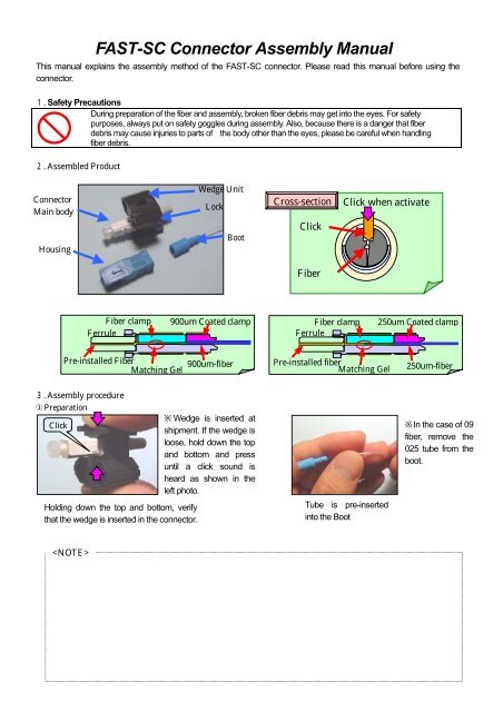
<strong>FAST</strong>-<strong>SC</strong> <strong>Connector</strong> <strong>Assembly</strong> <strong>Manual</strong><br />
This manual explains the assembly method of the <strong>FAST</strong>-<strong>SC</strong> connector. Please read this manual before using the<br />
connector.<br />
Safety Precautions<br />
During preparation of the fiber and assembly, broken fiber debris may get into the eyes. For safety<br />
purposes, always put on safety goggles during assembly. Also, because there is a danger that fiber<br />
debris may cause injuries to parts of the body other than the eyes, please be careful when handling<br />
fiber debris.<br />
Assembled Product<br />
<strong>Connector</strong><br />
Main body<br />
Housing<br />
Wedge Unit<br />
Lock<br />
Boot<br />
Cross-section<br />
Click<br />
Click when activate<br />
Fiber<br />
Fiber clamp<br />
Ferrule<br />
900um Coated clamp<br />
Fiber clamp<br />
Ferrule<br />
250um Coated clamp<br />
Pre-installed Fiber<br />
900um-fiber<br />
Matching Gel<br />
Pre-installed fiber<br />
Matching Gel<br />
250um-fiber<br />
<strong>Assembly</strong> procedure<br />
Preparation<br />
Click<br />
Holding down the top and bottom, verify<br />
that the wedge is inserted in the connector.<br />
Wedge is inserted at<br />
shipment. If the wedge is<br />
loose, hold down the top<br />
and bottom and press<br />
until a click sound is<br />
heard as shown in the<br />
left photo.<br />
Tube is pre-inserted<br />
into the Boot<br />
In the case of 09<br />
fiber, remove the<br />
025 tube from the<br />
boot.<br />
Fiber tip processing (Using the stripper and fiber cutter, fiber tip measurements on the right picture is achieved.)<br />
No gap<br />
Stripped<br />
Stripping Fiber cleaning Marking Screening Cut fiber with reference to the procedure<br />
0.25mm-fiber<br />
Coating part<br />
Marking<br />
Fiber<br />
10mm 10mm<br />
0.9mm-fiber<br />
Marking Coating part Fiber<br />
7mm 13mm<br />
Fiber Insertion and Hold<br />
Insert fiber slowly into the opening from back of<br />
connector main body. Insert fiber until marking is<br />
hidden and connection is made. Maintain the fiber<br />
connection while the fiber is bent.<br />
Marking Position<br />
Marking<br />
Connecting fiber<br />
Wedge Removal<br />
Press side of wedge when fiber is bent to remove<br />
wedge.<br />
Pre-installed fiber<br />
Wedge Removal Press side of wedge when fiber is bent to remove wedge<br />
0.25mm-fiber<br />
0.9mm-fiber<br />
Grip at about 10mm position.<br />
Approx.10mm<br />
Approx.10mm<br />
Press<br />
Grip at about 10mm position<br />
Fiber is not bent (Maintain<br />
connection force on fiber<br />
Press side of holder when fiber is<br />
connected.<br />
Press<br />
Press<br />
Press<br />
When fiber is bent<br />
Press side of wedge<br />
Wedge Structure<br />
Wedge<br />
Housing assembly Remove the lock and wedge, insert the housing and boot to complete<br />
Complete<br />
025mm-fiber<br />
Remove<br />
0.9mm-fiber<br />
Failure Checkpoint<br />
Condition Possible Cause Check point Picture<br />
Do not know where Marking is not done Marking is done following picture<br />
to insert fiber until therefore insertion 3..<br />
Marking<br />
depth is unclear.<br />
It is possible to insert fiber until<br />
Marking<br />
the marking is hidden.<br />
Connecting fiber<br />
Marking can reach up to 2mm<br />
into the opening at the rear of<br />
<br />
the connector<br />
Pre-Installed fiber<br />
Correct fiber insertion state<br />
Fiber cannot be<br />
inserted to the<br />
position of the<br />
marking.<br />
Wedge unit is<br />
removed but not reinstall<br />
back properly<br />
Wedge is not<br />
inserted<br />
Direction of wedge<br />
unit is wrong.<br />
The wedge is inserted into the<br />
connector following .<br />
The wedge unit and connector<br />
are direction-orientated refer to<br />
picture on right<br />
<br />
-<br />
<br />
Direction of lock is<br />
wrong<br />
The wedge unit and lock are<br />
direction-orientated refer to<br />
picture on right<br />