Bio-mimetic Sound Source Localization - Institute for Systems ...
Bio-mimetic Sound Source Localization - Institute for Systems ...
Bio-mimetic Sound Source Localization - Institute for Systems ...

You also want an ePaper? Increase the reach of your titles
YUMPU automatically turns print PDFs into web optimized ePapers that Google loves.
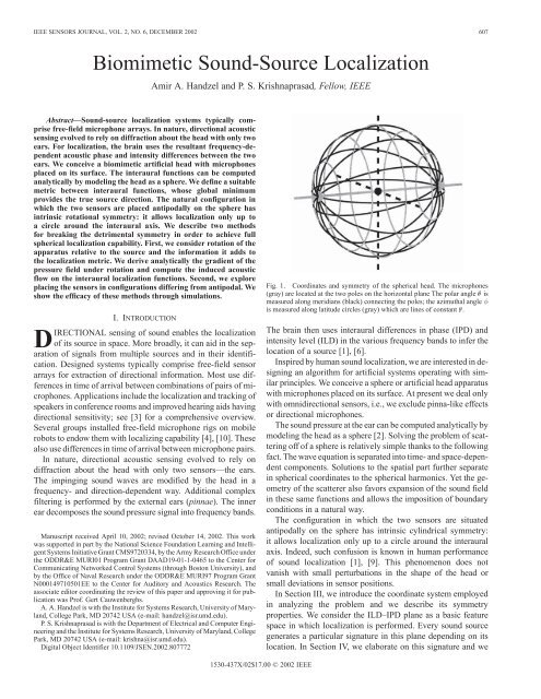
IEEE SENSORS JOURNAL, VOL. 2, NO. 6, DECEMBER 2002 607<br />
<strong>Bio</strong><strong>mimetic</strong> <strong>Sound</strong>-<strong>Source</strong> <strong>Localization</strong><br />
Amir A. Handzel and P. S. Krishnaprasad, Fellow, IEEE<br />
Abstract—<strong>Sound</strong>-source localization systems typically comprise<br />
free-field microphone arrays. In nature, directional acoustic<br />
sensing evolved to rely on diffraction about the head with only two<br />
ears. For localization, the brain uses the resultant frequency-dependent<br />
acoustic phase and intensity differences between the two<br />
ears. We conceive a bio<strong>mimetic</strong> artificial head with microphones<br />
placed on its surface. The interaural functions can be computed<br />
analytically by modeling the head as a sphere. We define a suitable<br />
metric between interaural functions, whose global minimum<br />
provides the true source direction. The natural configuration in<br />
which the two sensors are placed antipodally on the sphere has<br />
intrinsic rotational symmetry: it allows localization only up to<br />
a circle around the interaural axis. We describe two methods<br />
<strong>for</strong> breaking the detrimental symmetry in order to achieve full<br />
spherical localization capability. First, we consider rotation of the<br />
apparatus relative to the source and the in<strong>for</strong>mation it adds to<br />
the localization metric. We derive analytically the gradient of the<br />
pressure field under rotation and compute the induced acoustic<br />
flow on the interaural localization functions. Second, we explore<br />
placing the sensors in configurations differing from antipodal. We<br />
show the efficacy of these methods through simulations.<br />
I. INTRODUCTION<br />
DIRECTIONAL sensing of sound enables the localization<br />
of its source in space. More broadly, it can aid in the separation<br />
of signals from multiple sources and in their identification.<br />
Designed systems typically comprise free-field sensor<br />
arrays <strong>for</strong> extraction of directional in<strong>for</strong>mation. Most use differences<br />
in time of arrival between combinations of pairs of microphones.<br />
Applications include the localization and tracking of<br />
speakers in conference rooms and improved hearing aids having<br />
directional sensitivity; see [3] <strong>for</strong> a comprehensive overview.<br />
Several groups installed free-field microphone rigs on mobile<br />
robots to endow them with localizing capability [4], [10]. These<br />
also use differences in time of arrival between microphone pairs.<br />
In nature, directional acoustic sensing evolved to rely on<br />
diffraction about the head with only two sensors—the ears.<br />
The impinging sound waves are modified by the head in a<br />
frequency- and direction-dependent way. Additional complex<br />
filtering is per<strong>for</strong>med by the external ears (pinnae). The inner<br />
ear decomposes the sound pressure signal into frequency bands.<br />
Manuscript received April 10, 2002; revised October 14, 2002. This work<br />
was supported in part by the National Science Foundation Learning and Intelligent<br />
<strong>Systems</strong> Initiative Grant CMS9720334, by the Army Research Office under<br />
the ODDR&E MURI01 Program Grant DAAD19-01-1-0465 to the Center <strong>for</strong><br />
Communicating Networked Control <strong>Systems</strong> (through Boston University), and<br />
by the Office of Naval Research under the ODDR&E MURI97 Program Grant<br />
N000149710501EE to the Center <strong>for</strong> Auditory and Acoustics Research. The<br />
associate editor coordinating the review of this paper and approving it <strong>for</strong> publication<br />
was Prof. Gert Cauwenberghs.<br />
A. A. Handzel is with the <strong>Institute</strong> <strong>for</strong> <strong>Systems</strong> Research, University of Maryland,<br />
College Park, MD 20742 USA (e-mail: handzel@isr.umd.edu).<br />
P. S. Krishnaprasad is with the Department of Electrical and Computer Engineering<br />
and the <strong>Institute</strong> <strong>for</strong> <strong>Systems</strong> Research, University of Maryland, College<br />
Park, MD 20742 USA (e-mail: krishna@isr.umd.edu).<br />
Digital Object Identifier 10.1109/JSEN.2002.807772<br />
Fig. 1. Coordinates and symmetry of the spherical head. The microphones<br />
(gray) are located at the two poles on the horizontal plane The polar angle is<br />
measured along meridians (black) connecting the poles; the azimuthal angle <br />
is measured along latitude circles (gray) which are lines of constant .<br />
The brain then uses interaural differences in phase (IPD) and<br />
intensity level (ILD) in the various frequency bands to infer the<br />
location of a source [1], [6].<br />
Inspired by human sound localization, we are interested in designing<br />
an algorithm <strong>for</strong> artificial systems operating with similar<br />
principles. We conceive a sphere or artificial head apparatus<br />
with microphones placed on its surface. At present we deal only<br />
with omnidirectional sensors, i.e., we exclude pinna-like effects<br />
or directional microphones.<br />
The sound pressure at the ear can be computed analytically by<br />
modeling the head as a sphere [2]. Solving the problem of scattering<br />
off of a sphere is relatively simple thanks to the following<br />
fact. The wave equation is separated into time- and space-dependent<br />
components. Solutions to the spatial part further separate<br />
in spherical coordinates to the spherical harmonics. Yet the geometry<br />
of the scatterer also favors expansion of the sound field<br />
in these same functions and allows the imposition of boundary<br />
conditions in a natural way.<br />
The configuration in which the two sensors are situated<br />
antipodally on the sphere has intrinsic cylindrical symmetry:<br />
it allows localization only up to a circle around the interaural<br />
axis. Indeed, such confusion is known in human per<strong>for</strong>mance<br />
of sound localization [1], [9]. This phenomenon does not<br />
vanish with small perturbations in the shape of the head or<br />
small deviations in sensor positions.<br />
In Section III, we introduce the coordinate system employed<br />
in analyzing the problem and we describe its symmetry<br />
properties. We consider the ILD–IPD plane as a basic feature<br />
space in which localization is per<strong>for</strong>med. Every sound source<br />
generates a particular signature in this plane depending on its<br />
location. In Section IV, we elaborate on this signature and we<br />
1530-437X/02$17.00 © 2002 IEEE
608 IEEE SENSORS JOURNAL, VOL. 2, NO. 6, DECEMBER 2002<br />
Fig. 2.<br />
Signatures of two sources at different directions.<br />
introduce a suitable metric between interaural functions. Its<br />
global minimum should give the true source direction. Due<br />
to the inherent symmetry, however, a whole symmetric set<br />
of minima exist, which prevent unique localization. We then<br />
describe two methods <strong>for</strong> breaking the detrimental symmetry<br />
in order to achieve full spherical localization capability. In<br />
Section V, we derive an analytical expression <strong>for</strong> the change<br />
in the measured sound field due to rotation of the apparatus<br />
relative to the source. This derivative induces a “flow” of the<br />
interaural functions and the signature of a source. By adding<br />
this in<strong>for</strong>mation to the metric, we obtain a unique global<br />
minimum. This approach is motivated by psychophysical<br />
experiments which show that head rotation can improve human<br />
localization per<strong>for</strong>mance compared to static conditions [8],<br />
[11]. In Section VI, we explore an alternative method where we<br />
place the sensors in configurations that differ from antipodal.<br />
In order to establish notation, we start by briefly reviewing the<br />
known solution of acoustic scattering off of a sphere under<br />
static conditions [7].<br />
II. STATIC SPHERICAL SCATTERING<br />
The acoustic field can be described by small fluctuations in<br />
air pressure and local velocity , where is time<br />
and is a point in space. Thanks to the fact that the acoustic wave<br />
is irrotational, a velocity potential can be defined, such that<br />
. is a scalar function that serves as a dynamic variable<br />
from which all relevant fluctuating quantities are derived,<br />
including pressure: , where is the mass density of<br />
air. The velocity potential is governed by the wave equation<br />
where is the Laplacian.<br />
A solution to the wave equation is assumed to separate in time<br />
and space, i.e.,<br />
, giving time harmonic behavior<br />
while the spatial variables satisfy the Helmholtz<br />
equation<br />
A general solution of (2) is expressed through separation of variables<br />
in spherical coordinates, such that each variable is governed<br />
by an ODE: .<br />
The azimuthal function is harmonic<br />
and periodic on ,so are integers. The polar variable<br />
satisfies the associated Legendre equation whose solutions<br />
are the associated Legendre functions<br />
, where<br />
, is an integer, and . The associated<br />
functions reduce to the regular Legendre functions <strong>for</strong> :<br />
.<br />
The azimuthal functions are orthogonal, and the associated<br />
Legendre functions are orthogonal <strong>for</strong> different ’s with<br />
(1)<br />
(2)
HANDZEL AND KRISHNAPRASAD: BIOMIMETIC SOUND-SOURCE LOCALIZATION 609<br />
Fig. 3. The combined metric of the interaural functions exhibits the detrimental cylindrical symmetry: two global minima exist <strong>for</strong> any source direction in the<br />
horizontal plane.<br />
the same value of . The normalized product functions of these<br />
two families constitute the spherical harmonics<br />
The real functions<br />
may be used instead of the<br />
complex exponentials. Zonal harmonics are a subset of spherical<br />
harmonics which do not depend on azimuth ( ). They<br />
have nodal latitudinal circles that divide the sphere into zones<br />
(see Fig. 1). The spherical harmonics completely specify the angular<br />
dependence of solutions to the Helmholtz equation.<br />
A change of variable in the radial function to gives<br />
the Bessel equation. Its solutions are Bessel functions of order<br />
(<strong>for</strong> integer ). With suitable prefactors, the spherical<br />
Hänkel functions of the first kind are then defined as combinations<br />
of spherical Bessel functions of first ( ) and second ( )<br />
kinds<br />
The impinging wave and scattered wave are expanded<br />
in spherical harmonics and the position of the source and measurement<br />
points. Thanks to the orthonormality of spherical harmonics,<br />
the boundary conditions can be imposed independently<br />
(3)<br />
(4)<br />
<strong>for</strong> each component [2]. For an acoustically hard sphere, the<br />
normal velocity of the total wave vanishes on its surface (Neumann<br />
conditions)<br />
where is the radius of the sphere. Taking the sum of impinging<br />
and scattered waves as an expansion series, the total<br />
velocity potential is obtained <strong>for</strong> a general measurement point<br />
in space. When the measurement is per<strong>for</strong>med on<br />
the surface of the sphere , the spatial part of the potential<br />
is<br />
The field does not depend on the separate absolute angular positions<br />
of the source and sensor but on the angle between them.<br />
Then, if the source lies at position<br />
, the potential<br />
reduces to<br />
which we refer to hence<strong>for</strong>th.<br />
III. COORDINATES AND SYMMETRY OF THE PROBLEM<br />
We refer to the coordinate system that is determined naturally<br />
by the geometry of the apparatus. We designate a “north” pole as<br />
(5)<br />
(6)<br />
(7)
610 IEEE SENSORS JOURNAL, VOL. 2, NO. 6, DECEMBER 2002<br />
Fig. 4. The combined metric of the interaural functions exhibits the detrimental cylindrical symmetry. The skew diagonals are zeros of the metric in addition to<br />
the diagonal.<br />
the position of the sensor. When two sensors are placed in the<br />
antipodal configuration, we assign the left sensor as the north<br />
pole; see Fig. 1. The polar angle is measured along meridians<br />
between the north and south poles and is constant along<br />
circles of latitude relative to the two poles. The azimuthal angle<br />
marks the position on latitude circles; in other words, it marks<br />
the meridian between the poles relative to the horizontal. For the<br />
present problem, we set the latitude of the equator to ,so<br />
antipodal sensors are located at .<br />
Symmetry properties of the problem govern its solution and<br />
characteristics. The scattering configuration has cylindrical<br />
symmetry, because the total pressure (7) depends only on the<br />
polar angle. The same pressure will be measured on the circles<br />
of latitude. In other words, rotations about the interaural axis<br />
(gray), i.e., by the azimuthal angle , leave the measured<br />
pressure invariant. The sound source, the sensor, and the center<br />
of the sphere all lie on a plane at all times, even though this<br />
plane may rotate as the source rotates relative to the sphere. The<br />
collection of these symmetry rotations constitutes the Lie group<br />
SO(2). This symmetry still holds and the geometry remains the<br />
same when a second sensor is added antipodally to the first.<br />
Due to the topology of the sphere, the cylindrical symmetry<br />
gives rise to additional discrete ambiguity within the sensorsource<br />
plane. For any given polar angle , the circle of<br />
azimuthal symmetry intersects the plane at a mirror point<br />
with ( ). In psychophysics, this is referred<br />
to as front–back symmetry.<br />
IV. LOCALIZATION SIGNATURES AND METRIC<br />
The measured sound pressure (7) is a complex response to<br />
the excitation by a source<br />
where is the part of the phase containing spatial in<strong>for</strong>mation.<br />
With pressure measured at the right (R) and left (L) sensors, we<br />
define the ILD and ILP as<br />
The solution of the wave equation involved separation into frequency<br />
components. Consequently, both ILD( ) and IPD( )<br />
are functions of frequency . We consider the ILD–IPD plane<br />
as a basic feature space in which localization is per<strong>for</strong>med.<br />
For every source direction and frequency there is a point in<br />
the ILD–IPD plane. Since ILD and IPD depend smoothly<br />
on frequency, every broad-band sound source generates a<br />
whole curve in this plane which is its specific signature,<br />
depending on the source location in space. Fig. 2 shows the<br />
signatures of two broad-band sources located at different<br />
directions. For each source, frequency is sampled at equal<br />
intervals in the range in which diffraction is relevant. It roughly<br />
corresponds to the human audible range <strong>for</strong> a sphere of human<br />
head size. In Fig. 2 the plane should be viewed as the unwrapping<br />
of a cylinder since the IPD values of 360 and 0 are to<br />
be identified. Thus, there are exactly two continuous curves<br />
(8)<br />
(9)
HANDZEL AND KRISHNAPRASAD: BIOMIMETIC SOUND-SOURCE LOCALIZATION 611<br />
Fig. 5. Vector field of pressure in the plane of phase versus log-intensity <strong>for</strong> a distant source at a 90 angle of incidence from the sensor.<br />
Fig. 6.<br />
Derivative of sound field under rotation separates identical signatures of sources at different yet symmetric directions.<br />
in the figure corresponding to 30 and 60 source locations,<br />
with a branch hitting the IPD line joining an appropriate<br />
branch hitting the IPD .<br />
We want to quantify how close are the localization functions<br />
(ILD, IPD) or signature curves of different directions. The goal<br />
is to identify the direction of a source by the following proce-
612 IEEE SENSORS JOURNAL, VOL. 2, NO. 6, DECEMBER 2002<br />
Fig. 7.<br />
Unique localization with derivative in<strong>for</strong>mation. The total metric has a single global minimum <strong>for</strong> each source direction.<br />
dure: compare the measured ILD and IPD to their values <strong>for</strong> all<br />
possible directions, and pick the direction <strong>for</strong> which the calculated<br />
functions are the closest to those measured. Given a source<br />
direction , we define the distance-measuring functions based<br />
on the norm squared<br />
(10)<br />
and similarly <strong>for</strong> ILD. We normalize each metric with respect<br />
to its maximal value on the torus domain<br />
(11)<br />
We then combine the normalized metrics <strong>for</strong> ILD and IPD to<br />
yield<br />
(12)<br />
which takes into account all static binaural in<strong>for</strong>mation.<br />
The structural symmetry of the problem is carried over to the<br />
combined metric. It prevents unique localization, as can be seen<br />
in Figs. 3 and 4. In Fig. 3, the metric <strong>for</strong> sources at direction<br />
45 has typical double minima. Only in the special case where<br />
a source lies exactly at on the interaural axis, i.e., at 90 or<br />
270 , does a single minimum exist. The general picture is seen<br />
in Fig. 4 which shows the distance metric between all combinations<br />
of source and test directions. Double global minima corresponding<br />
to the front–back symmetric points appear as zeros<br />
of the metric on the skew diagonal.<br />
V. ACOUSTIC FLOW UNDER ROTATION<br />
As described in Section III, azimuthal rotations leave the configuration<br />
of source and sensor invariant while polar rotations<br />
modify the field. Rotations in the polar angle are a representation<br />
of the rotation group SO(2) over zonal spherical harmonics.<br />
Infinitesimal rotations are a representation of the corresponding<br />
one-dimensional (1-D) Lie algebra which acts<br />
by differentiation of functions with respect to (w.r.t.) the polar<br />
angle. For the measured sound pressure (8), the derivative is<br />
. With normalization by the response<br />
itself, properties of the complex give<br />
(13)<br />
The real part is the normalized infinitesimal change in amplitude<br />
and the imaginary part is the derivative of the phase.<br />
Pressure is expressed as an expansion in the regular Legendre<br />
functions which are the zonal spherical harmonics, with the coefficients<br />
being functions of distance<br />
(14)
HANDZEL AND KRISHNAPRASAD: BIOMIMETIC SOUND-SOURCE LOCALIZATION 613<br />
Fig. 8.<br />
Unique localization with derivative in<strong>for</strong>mation. The zeros of the total metric are on the diagonal.<br />
The derivative is there<strong>for</strong>e also an expansion in zonal harmonics<br />
(15)<br />
Since the coefficients in the expansion are radial functions, all<br />
we need are the derivatives of the Legendre functions with respect<br />
to the polar angle . A recurrence relation gives<br />
(16)<br />
For computational purposes, it is more convenient to retain<br />
the original coefficients in the expansion, instead of<br />
reordering according to the Legendre functions<br />
(17)<br />
Equations (13) and (17) now enable us to compute the derivative<br />
of measured acoustic pressure <strong>for</strong> a time-harmonic point source.<br />
An example of the infinitesimal change in pressure is shown in<br />
Fig. 5. The static response relative to the free-field sound pressure<br />
is plotted in the plane of phase versus log-intensity <strong>for</strong> a<br />
distant source at 90 angle from a sensor. The points are samples<br />
of log-frequency at 0.01 intervals. At each frequency point<br />
, the derivative of the response can be considered a vector<br />
in the plane. At the low frequencies, very little change is induced<br />
by rotation, because the sphere causes little interference<br />
in the propagation of the sound wave. It increases dramatically<br />
both <strong>for</strong> phase and intensity with increasing frequency. At the<br />
high-frequency end, the picture becomes more complicated due<br />
to intricate diffraction patterns.<br />
Having computed the derivative of sound pressure <strong>for</strong> each<br />
sensor, the derivatives of the interaural functions are given by<br />
(18)<br />
Just as <strong>for</strong> a single sensor, the derivatives of the interaural functions<br />
give a vector attached to the signature curve at each frequency<br />
.<br />
Whereas the interaural functions have cylindrical symmetry<br />
in each lateral hemisphere, the derivative functions have a<br />
right–left symmetry about the mid-sagittal plane (i.e., the plane<br />
perpendicular to the interaural axis intersecting its mid-point).<br />
Fig. 6 shows how these vectors separate overlapping signatures<br />
of sources in two different locations. <strong>Source</strong>s at directions 45<br />
and 135 have the same signature due to the azimuthal SO(2)<br />
symmetry. However, the vector fields induced by rotation are<br />
the mirror of each other, thus removing the symmetry.<br />
If the rotation is not purely polar, then only the polar component<br />
induces flow of the signature. The derivatives of pressure<br />
are multiplied by cosine the angle between the plane of rotation<br />
and the plane determined by the source and sensors. When,<br />
<strong>for</strong> example, rotation is in the horizontal plane, i.e., around the<br />
vertical axis, and the source has azimuthal angle —which is
614 IEEE SENSORS JOURNAL, VOL. 2, NO. 6, DECEMBER 2002<br />
Fig. 9. Near-optimal sensor placement at 50 with 100 angle between the pair. The metric has a single global minimum <strong>for</strong> each source direction.<br />
identical to elevation in this case—then the derivative is multiplied<br />
by . Hence, <strong>for</strong> horizontal rotations, the resultant<br />
derivatives are modulated by the elevation angle of the source.<br />
In Fig. 6, the two vectors which emanate from each frequency<br />
point belong to the two mirror directions having pure<br />
polar rotation. For any other azimuthal angle, the induced vector<br />
will have length multiplied by .<br />
In order to take advantage of this symmetry breaking, we define<br />
metrics <strong>for</strong> the dynamic cues as<br />
(19)<br />
and similarly <strong>for</strong> ILD. Finally, the total metric comprises four<br />
terms<br />
(20)<br />
The inclusion of the derivative functions in the metric provides<br />
a unique global minimium <strong>for</strong> a given source direction. Figs. 7<br />
and 8 show the removal of the front–back symmetry. In Fig. 7,<br />
the metric <strong>for</strong> sources at directions 45 and 135 are distinct and<br />
have unique minima. The composite metric between all combinations<br />
of source and test directions is given in Fig. 8. The<br />
unique minimum appears as zero on the diagonal. This procedure<br />
can be generalized <strong>for</strong> all azimuthal angles .<br />
VI. OPTIMAL SENSOR PLACEMENT FOR LOCALIZATION<br />
We explore another method <strong>for</strong> achieving unique localization.<br />
Instead of breaking the symmetry inherent in the antipodal<br />
configuration, we ask whether different sensor placement can<br />
provide good overall localization per<strong>for</strong>mance over all source<br />
directions . This could be determined either by least worst<br />
case (min–max) or on average over all angles. Preliminary simulations<br />
reveal an important structural feature that seems dominant.<br />
Although the antipodal placement may have the advantage<br />
of best total acoustic signal reception intensity, it is detrimental<br />
to localization. By shifting the sensor position from the 90<br />
position, the distance functions change in a regular manner in<br />
the shift parameter<br />
. Moving the sensors to a<br />
more <strong>for</strong>ward position gradually removes the unwanted symmetry<br />
until it vanishes at – . Around 50 , other “topological”<br />
structures appear, in particular, a flat basin emerges in<br />
around the diagonal at 110 . Figs. 9 and 10 show the<br />
localization metric <strong>for</strong> near-optimal sensor placement at 50<br />
with the corresponding angle between the sensors being 100 .<br />
A unique global minimum exists <strong>for</strong> every source direction, although<br />
the depth of the troughs in the metric around the minima<br />
is shallower than that of the composite metric with flow (compare<br />
to Fig. 7). Vestiges of the fictitious minima appear as a<br />
shifted shallow skew diagonal in Fig. 10. This approach seems<br />
promising but additional work is needed to elaborate on the<br />
results.
HANDZEL AND KRISHNAPRASAD: BIOMIMETIC SOUND-SOURCE LOCALIZATION 615<br />
Fig. 10. Near-optimal sensor placement at 50 : the zeros of the metric are on the diagonal. Vestiges of the fictitious symmetric minima appear as a shifted shallow<br />
skew diagonal.<br />
VII. CONCLUDING REMARKS<br />
We have analyzed sound-source localization with a<br />
bio<strong>mimetic</strong> apparatus comprising a pair of sensors on the<br />
surface of a spherical artificial head. In contrast to free-field arrays,<br />
diffraction about the head provides additional directional<br />
in<strong>for</strong>mation. With a pair of sensors—whether free-field or in an<br />
antipodal arrangement on the sphere—localization is possible<br />
only up to a circle of directions due to the inherent symmetry<br />
of the problem. If enough microphones are included in an<br />
array, unique localization is possible by using intermicrophone<br />
in<strong>for</strong>mation of several pair combinations. We showed here<br />
that unique loclization can be achieved with only two sensors<br />
by combining implicit in<strong>for</strong>mation from diffraction with the<br />
derivative of the sound field under rotation. An alternative<br />
method would be to place the sensors in an asymmetric configuration<br />
such that the angle subtended between the two is<br />
around 100 .<br />
Compared with one sensor, IPD and ILD provide substantial<br />
in<strong>for</strong>mation which is not available monaurally. Binaural<br />
functions have another important advantage: the comparison<br />
between two sensors obviates the need to know or assume<br />
much about the character of the source signal. Mathematically<br />
this can be expressed as the difference in log-intensity or<br />
phases. As can be seen from (13), the normalized flow has<br />
the same beneficial feature. It is reminiscent of the similarity<br />
between recovery of visual depth in stereovision and scene<br />
reconstruction from a sequence of monocular moving images<br />
[5].<br />
REFERENCES<br />
[1] J. Blauert, Spatial Hearing, revised ed. Cambridge, MA: MIT Press,<br />
1997.<br />
[2] J. Bowman, T. Senior, and P. Uslenghi, Electromagnetic and Acoustic<br />
Scattering by Simple Shapes. Amsterdam, The Netherlands: North-<br />
Holland, 1969.<br />
[3] M. Brandstein and D. Ward, Eds., “Microphone arrays,” in Digital<br />
Signal Processing. Berlin, Germany: Springer-Verlag, 2002.<br />
[4] J. Huang et al., “A model-based sound localization system and its application<br />
to robot navigation,” Robot. Auton. Syst., vol. 27, no. 4, pp.<br />
199–209, 1999.<br />
[5] R. Hartley and A. Zisserman, Multiple View Geometry in Computer Vision.<br />
Cambridge, U.K.: Cambridge Univ. Press, 2000.<br />
[6] W. M. Hartmann, “How we localize sound,” Phys. Today, pp. 24–29,<br />
Nov. 1999.<br />
[7] P. M. Morse and K. U. Ingard, Theoretical Acoustics, ser. International<br />
Series in Pure and Applied Physics. New York: McGraw-Hill, 1968.<br />
[8] S. Perret and W. Noble, “The effect of head rotations on vertical<br />
plane sound localization,” J. Acoust. Soc. Amer., vol. 102, no. 4, pp.<br />
2325–2332, 1997.<br />
[9] B. G. Shinn-Cunningham, S. Santarelli, and N. Kopco, “Tori of confusion:<br />
Binaural localization cues <strong>for</strong> sources within reach of a listener,”<br />
J. Acoust. Soc. Amer., vol. 107, no. 3, pp. 1627–1636, Mar. 2000.<br />
[10] J. Weng and K. Y. Guentchev, “Three-dimensional sound localization<br />
from a compact noncoplanar array of microphones using tree-based<br />
learning,” J. Acoust. Soc. Amer., vol. 110, no. 1, pp. 310–323, Jul. 2001.<br />
[11] F. L. Wightman and D. J. Kistler, “Resolution of front–back ambiguity in<br />
spatial hearing by listener and source movement,” J. Acoust. Soc. Amer.,<br />
vol. 105, no. 5, pp. 2841–2853, May 1999.
616 IEEE SENSORS JOURNAL, VOL. 2, NO. 6, DECEMBER 2002<br />
Amir A. Handzel received the B.Sc. degree in physics from the Hebrew University,<br />
Jerusalem, Israel, in 1991, the M.Sc. degree in physics from the Weizmann<br />
<strong>Institute</strong> of Science, Rehovot, Israel, in 1993, and the Ph.D. degree in applied<br />
mathematics from the Weizmann <strong>Institute</strong> in 2000.<br />
He is currently a Research Associate at the <strong>Institute</strong> <strong>for</strong> <strong>Systems</strong> Research at<br />
the University of Maryland, College Park. His research interests are in the mathematical<br />
analysis and modeling of sensory-motor systems, neural processing,<br />
bio<strong>mimetic</strong> engineering, and acoustic signal processing.<br />
P. S. Krishnaprasad (S’73–M’77–SM’89–F’90)<br />
received the Ph.D. degree from Harvard University,<br />
Cambridge, MA, in 1977.<br />
He was on the faculty of the <strong>Systems</strong> Engineering<br />
Department at Case Western Reserve University,<br />
Cleveland, OH, from 1977 to 1980. He has been<br />
with the University of Maryland, College Park, since<br />
August 1980, where he has held the position of<br />
Professor of Electrical Engineering since 1987 and<br />
a joint appointment with the <strong>Institute</strong> <strong>for</strong> <strong>Systems</strong><br />
Research since 1988. He is also a member of the<br />
Applied Mathematics Faculty. He has held visiting positions with Erasmus<br />
University, Rotterdam, Germany; the Department of Mathematics, University<br />
of Cali<strong>for</strong>nia, Berkeley; the University of Groningen, The Netherlands; the<br />
Mathematical Sciences <strong>Institute</strong> at Cornell University, Ithaca, NY; and the<br />
Mechanical and Aerospace Engineering Department at Princeton University,<br />
Princeton, NJ. Guided by a central interest in geometric control theory,<br />
geometric mechanics, Lie groups, and distributed parameter systems, he has<br />
made contributions to the study of the geometry of parameterization of linear<br />
systems, the Lie algebraic foundations of some nonlinear filtering problems<br />
arising in system identification, the Lie theory and stability of interconnected<br />
mechanical systems (e.g., spacecraft with elastic attachments, spinning rotors,<br />
and fluid-filled cavities), and symmetry principles in nonlinear control theory.<br />
In recent years, he has worked on problems of modeling, design, motion<br />
planning, and control arising in mobile robotics (legged and wheeled vehicles,<br />
autonomous underwater vehicles and autonomous aircraft), geometric methods<br />
in nonlinear dynamics, time–frequency analysis of acoustic signals and systems,<br />
intelligent control architectures, in part inspired by biological paradigms<br />
such as central patterns generators and neuronal networks, the technology and<br />
theory of smart materials such as piezo-electric and magnetostrictive materials<br />
<strong>for</strong> use in actuation and sensing, problems of high-resolution optical wave<br />
front control, and problems of integration of actuators and sensors in control<br />
networks.<br />
Dr. Krishnaprasad was elected a Fellow of the IEEE in 1990 <strong>for</strong> his<br />
contributions to geometric and nonlinear control and engineering education.<br />
He was appointed a 1998–2000 Distinguished Faculty Research Fellow of the<br />
University of Maryland.