effects of the multiple internal reflection and sample thickness ...
effects of the multiple internal reflection and sample thickness ...
effects of the multiple internal reflection and sample thickness ...

Create successful ePaper yourself
Turn your PDF publications into a flip-book with our unique Google optimized e-Paper software.
E. Nitiss et al. / Lith. J. Phys. 52, 30–38 (2012) 31<br />
spite <strong>of</strong> high sensitivity to acoustic <strong>and</strong> mechanical<br />
vibrations, <strong>the</strong> Mach–Zehnder interferometric<br />
(MZI) techniques in <strong>the</strong> transmission or in <strong>the</strong> <strong>reflection</strong><br />
mode are being applied more <strong>and</strong> more<br />
<strong>of</strong>ten [7, 8]. Researchers using <strong>the</strong> MZI technique<br />
in <strong>the</strong> transmission mode have mostly excluded<br />
<strong>multiple</strong> <strong>internal</strong> <strong>reflection</strong>s <strong>and</strong> <strong>thickness</strong> change<br />
<strong>of</strong> <strong>the</strong> <strong>sample</strong> by electrostriction <strong>and</strong> piezoelectric<br />
<strong>effects</strong> from <strong>the</strong>ir considerations. To our knowledge,<br />
a limited number <strong>of</strong> investigators pay attention<br />
to <strong>the</strong>se <strong>effects</strong> [9–11]; however, according<br />
to our observations, <strong>the</strong> <strong>effects</strong> can contribute<br />
greatly to <strong>the</strong> measured modulated signal amplitude<br />
<strong>and</strong> phase <strong>and</strong> <strong>the</strong>refore must be taken into<br />
account. For correct determination <strong>of</strong> both EO<br />
coefficients <strong>the</strong> light intensity <strong>and</strong> phase transmitted<br />
by <strong>the</strong> multilayer EO <strong>sample</strong> must be known.<br />
It can be described by <strong>the</strong> Abelès matrix formalism<br />
[12, 13]. In this contribution we would like<br />
to present <strong>the</strong> influence <strong>of</strong> <strong>the</strong> <strong>multiple</strong> <strong>internal</strong><br />
<strong>reflection</strong> <strong>and</strong> <strong>sample</strong> <strong>thickness</strong> change <strong>effects</strong> on<br />
<strong>the</strong> determination <strong>of</strong> polymer film EO coefficients<br />
using <strong>the</strong> MZI technique.<br />
2. Experimental set-up<br />
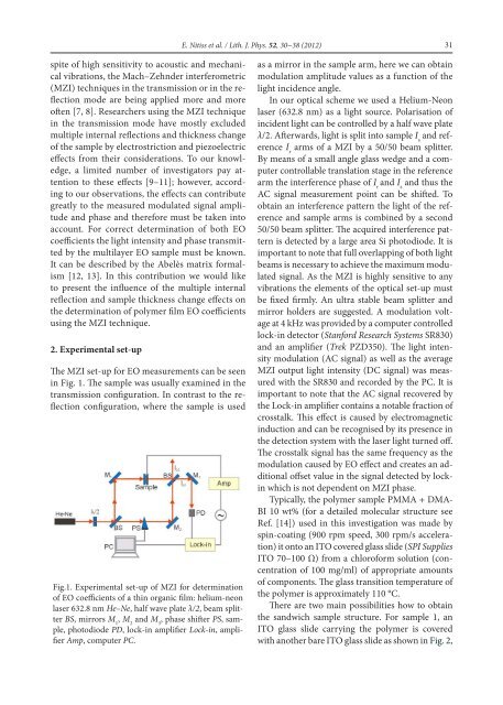
The MZI set-up for EO measurements can be seen<br />
in Fig. 1. The <strong>sample</strong> was usually examined in <strong>the</strong><br />
transmission configuration. In contrast to <strong>the</strong> <strong>reflection</strong><br />
configuration, where <strong>the</strong> <strong>sample</strong> is used<br />
Fig.1. Experimental set-up <strong>of</strong> MZI for determination<br />
<strong>of</strong> EO coefficients <strong>of</strong> a thin organic film: helium-neon<br />
laser 632.8 nm He–Ne, half wave plate λ/2, beam splitter<br />
BS, mirrors M 1<br />
, M 2<br />
<strong>and</strong> M 3<br />
, phase shifter PS, <strong>sample</strong>,<br />
photodiode PD, lock-in amplifier Lock-in, amplifier<br />
Amp, computer PC.<br />
as a mirror in <strong>the</strong> <strong>sample</strong> arm, here we can obtain<br />
modulation amplitude values as a function <strong>of</strong> <strong>the</strong><br />
light incidence angle.<br />
In our optical scheme we used a Helium-Neon<br />
laser (632.8 nm) as a light source. Polarisation <strong>of</strong><br />
incident light can be controlled by a half wave plate<br />
λ/2. Afterwards, light is split into <strong>sample</strong> I s<br />
<strong>and</strong> reference<br />
I r<br />
arms <strong>of</strong> a MZI by a 50/50 beam splitter.<br />
By means <strong>of</strong> a small angle glass wedge <strong>and</strong> a computer<br />
controllable translation stage in <strong>the</strong> reference<br />
arm <strong>the</strong> interference phase <strong>of</strong> I r<br />
<strong>and</strong> I s<br />
<strong>and</strong> thus <strong>the</strong><br />
AC signal measurement point can be shifted. To<br />
obtain an interference pattern <strong>the</strong> light <strong>of</strong> <strong>the</strong> reference<br />
<strong>and</strong> <strong>sample</strong> arms is combined by a second<br />
50/50 beam splitter. The acquired interference pattern<br />
is detected by a large area Si photodiode. It is<br />
important to note that full overlapping <strong>of</strong> both light<br />
beams is necessary to achieve <strong>the</strong> maximum modulated<br />
signal. As <strong>the</strong> MZI is highly sensitive to any<br />
vibrations <strong>the</strong> elements <strong>of</strong> <strong>the</strong> optical set-up must<br />
be fixed firmly. An ultra stable beam splitter <strong>and</strong><br />
mirror holders are suggested. A modulation voltage<br />
at 4 kHz was provided by a computer controlled<br />
lock-in detector (Stanford Research Systems SR830)<br />
<strong>and</strong> an amplifier (Trek PZD350). The light intensity<br />
modulation (AC signal) as well as <strong>the</strong> average<br />
MZI output light intensity (DC signal) was measured<br />
with <strong>the</strong> SR830 <strong>and</strong> recorded by <strong>the</strong> PC. It is<br />
important to note that <strong>the</strong> AC signal recovered by<br />
<strong>the</strong> Lock-in amplifier contains a notable fraction <strong>of</strong><br />
crosstalk. This effect is caused by electromagnetic<br />
induction <strong>and</strong> can be recognised by its presence in<br />
<strong>the</strong> detection system with <strong>the</strong> laser light turned <strong>of</strong>f.<br />
The crosstalk signal has <strong>the</strong> same frequency as <strong>the</strong><br />
modulation caused by EO effect <strong>and</strong> creates an additional<br />
<strong>of</strong>fset value in <strong>the</strong> signal detected by lockin<br />
which is not dependent on MZI phase.<br />
Typically, <strong>the</strong> polymer <strong>sample</strong> PMMA + DMA-<br />
BI 10 wt% (for a detailed molecular structure see<br />
Ref. [14]) used in this investigation was made by<br />
spin-coating (900 rpm speed, 300 rpm/s acceleration)<br />
it onto an ITO covered glass slide (SPI Supplies<br />
ITO 70–100 Ω) from a chlor<strong>of</strong>orm solution (concentration<br />
<strong>of</strong> 100 mg/ml) <strong>of</strong> appropriate amounts<br />
<strong>of</strong> components. The glass transition temperature <strong>of</strong><br />
<strong>the</strong> polymer is approximately 110 °C.<br />
There are two main possibilities how to obtain<br />
<strong>the</strong> s<strong>and</strong>wich <strong>sample</strong> structure. For <strong>sample</strong> 1, an<br />
ITO glass slide carrying <strong>the</strong> polymer is covered<br />
with ano<strong>the</strong>r bare ITO glass slide as shown in Fig. 2,