AUO - M240HW02 V6
AUO - M240HW02 V6
AUO - M240HW02 V6

Create successful ePaper yourself
Turn your PDF publications into a flip-book with our unique Google optimized e-Paper software.
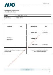
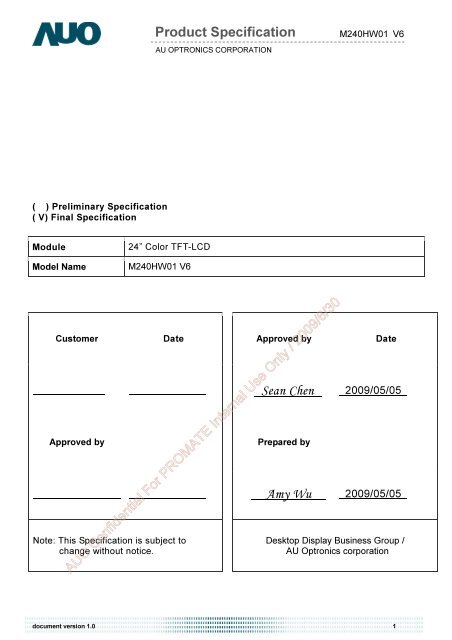
( ) Preliminary Specification<br />
( V) Final Specification<br />
Module 24” Color TFT-LCD<br />
Model Name M240HW01 <strong>V6</strong><br />
Customer Date<br />
Approved by<br />
Note: This Specification is subject to<br />
change without notice.<br />
Product Specification M240HW01 <strong>V6</strong><br />
AU OPTRONICS CORPORATION<br />
Approved by Date<br />
Sean Chen 2009/05/05<br />
Prepared by<br />
Amy Wu 2009/05/05<br />
Desktop Display Business Group /<br />
AU Optronics corporation<br />
<strong>AUO</strong> Confidential For PROMATE Internal Use Only / 2009/6/30<br />
document version 1.0 1
Product Specification M240HW01 <strong>V6</strong><br />
AU OPTRONICS CORPORATION<br />
Contents<br />
1.0 Handling Precautions .....................................................................................4<br />
2.0 General Description ........................................................................................5<br />
2.1 Display Characteristics....................................................................................................... 5<br />
2.2 Optical Characteristics ....................................................................................................... 6<br />
3.0 Functional Block Diagram ............................................................................10<br />
4.0 Absolute Maximum Ratings .........................................................................11<br />
4.1 TFT LCD Module.............................................................................................................. 11<br />
4.2 Backlight Unit ................................................................................................................... 11<br />
4.3 Absolute Ratings of Environment..................................................................................... 11<br />
5.0 Electrical characteristics..............................................................................12<br />
5.1 TFT LCD Module.............................................................................................................. 12<br />
5.1.1 Power Specification ...................................................................................................................................... 12<br />
5.1.2 Signal Electrical Characteristics ................................................................................................................... 13<br />
5.2 Backlight Unit ................................................................................................................... 14<br />
6.0 Signal Characteristic.....................................................................................15<br />
6.1 Pixel Format Image.......................................................................................................... 15<br />
6.2 The input data format....................................................................................................... 15<br />
6.3 Signal Description ............................................................................................................ 16<br />
6.4 Timing Characteristics...................................................................................................... 18<br />
6.5 Timing diagram ................................................................................................................ 19<br />
6.6 Power ON/OFF Sequence ............................................................................................... 19<br />
7.0 Connector & Pin Assignment.......................................................................21<br />
7.1 TFT LCD Module.............................................................................................................. 21<br />
7.1.1 Pin Assignment............................................................................................................................................. 21<br />
7.2 Recommend connector for Backlight Unit........................................................................ 22<br />
7.2.1 Pin assignment ............................................................................................................................................. 22<br />
8.0 Reliability Test...............................................................................................23<br />
9.0 Shipping Label ..............................................................................................24<br />
10.0 Mechanical Characteristics ........................................................................25<br />
<strong>AUO</strong> Confidential For PROMATE Internal Use Only / 2009/6/30<br />
document version 1.0 2
Version and<br />
Date<br />
0.1<br />
2009/03/24<br />
1.0<br />
2009/05/05<br />
Product Specification M240HW01 <strong>V6</strong><br />
AU OPTRONICS CORPORATION<br />
Record of Revision<br />
Page Old description New Description Remark<br />
First Version<br />
Final Version<br />
<strong>AUO</strong> Confidential For PROMATE Internal Use Only / 2009/6/30<br />
document version 1.0 3
1.0 Handling Precautions<br />
Product Specification M240HW01 <strong>V6</strong><br />
AU OPTRONICS CORPORATION<br />
1) Since front polarizer is easily damaged, pay attention not to scratch it.<br />
2) Be sure to turn off power supply when inserting or disconnecting from input connector.<br />
3) Wipe off water drop immediately. Long contact with water may cause discoloration or spots.<br />
4) When the panel surface is soiled, wipe it with absorbent cotton or other soft cloth.<br />
5) Since the panel is made of glass, it may break or crack if dropped or bumped on hard<br />
surface.<br />
6) Since CMOS LSI is used in this module, take care of static electricity and insure human earth<br />
when handling.<br />
7) Do not open or modify the Module Assembly.<br />
8) Do not press the reflector sheet at the back of the module to any directions.<br />
9) In case if a Module has to be put back into the packing container slot after once it was taken<br />
out from the container, do not press the center of the LED lightbar edge. Instead, press at the<br />
far ends of the LED light bar edge softly. Otherwise the TFT Module may be damaged.<br />
10) At the insertion or removal of the Signal Interface Connector, be sure not to rotate nor tilt the<br />
Interface Connector of the TFT Module.<br />
11) After installation of the TFT Module into an enclosure, do not twist nor bend the TFT Module<br />
even momentary. At designing the enclosure, it should be taken into consideration that no<br />
bending/twisting forces are applied to the TFT Module from outside. Otherwise the TFT<br />
Module may be damaged.<br />
12) Small amount of materials having no flammability grade is used in the LCD module. The LCD<br />
module should be supplied by power complied with requirements of Limited Power Source<br />
(IEC60950 or UL1950), or be applied exemption.<br />
<strong>AUO</strong> Confidential For PROMATE Internal Use Only / 2009/6/30<br />
document version 1.0 4
2.0 General Description<br />
Product Specification<br />
AU OPTRONICS CORPORATION<br />
M240HW01 <strong>V6</strong><br />
This specification applies to the 24 inch-FHD Color a-Si TFT-LCD Module M240HW01. The<br />
display supports the FHD - 1920(H) x 1080(V) screen format and 16.7M colors (RGB 6-bits +<br />
Hi-FRC data). The light source of this TFT-LCD module is W-LED. All input signals are 2-channel<br />
LVDS interface and this module doesn’t contain a driver for backlight.<br />
2.1 Display Characteristics<br />
The following items are characteristics summary on the table under 25℃ condition:<br />
ITEMS Unit SPECIFICATIONS<br />
Screen Diagonal [mm] 609.7(24.0”)<br />
Active Area [mm] 531.36 (H) x 298.89 (V)<br />
Pixels H x V 1920(x3) x 1080<br />
Pixel Pitch [um] 276.75 (per one triad) ×276.75<br />
Pixel Arrangement R.G.B. Vertical Stripe<br />
Display Mode TN Mode, Normally White<br />
White Luminance ( Center ) [cd/m 2 ] 250 cd/m 2 (Typ.)<br />
Contrast Ratio 1000(Typ.)<br />
Optical Response Time [msec] 5ms (Typ., on/off)<br />
Nominal Input Voltage VDD [Volt] +5.0 V (Typ)<br />
Power Consumption<br />
(VDD line + LED line)<br />
[Watt] 21W<br />
Weight [Grams] 2190 Typ.<br />
Physical Size [mm] 556.0(H)x323.2(V)x9.90(D)<br />
Electrical Interface Dual channel LVDS<br />
Support Color 16.7M colors (RGB 6-bit + Hi_FRC )<br />
Surface Treatment<br />
Temperature Range<br />
Anti-Glare, 3H<br />
Operating<br />
[<br />
Storage (Shipping)<br />
o C]<br />
[ o 0 to +50<br />
C] -20 to +60<br />
RoHS Compliance RoHS Compliance<br />
<strong>AUO</strong> Confidential For PROMATE Internal Use Only / 2009/6/30<br />
document version 1.0 5
2.2 Optical Characteristics<br />
Product Specification<br />
AU OPTRONICS CORPORATION<br />
The optical characteristics are measured under stable conditions at 25℃:<br />
M240HW01 <strong>V6</strong><br />
Item Unit Conditions Min. Typ. Max. Note<br />
Viewing Angle [degree]<br />
Horizontal (Right)<br />
CR = 10 (Left)<br />
Vertical (Up)<br />
CR = 10 (Down)<br />
Contrast ratio Normal Direction<br />
Response Time [msec]<br />
Color / Chromaticity<br />
Coordinates (CIE)<br />
Color Coordinates (CIE) White<br />
Raising Time (TrR)<br />
Falling Time (TrF)<br />
Raising + Falling<br />
document version 1.0 6<br />
150<br />
140<br />
600<br />
-<br />
-<br />
-<br />
170<br />
160<br />
-<br />
-<br />
-<br />
-<br />
2<br />
1000 - 3<br />
3.5 7.4<br />
1.5 2.6<br />
5 10<br />
Red x 0.608 0.638 0.668<br />
Red y 0.318 0.348 0.378<br />
Green x 0.304 0.334 0.364<br />
Green y 0.578 0.608 0.638<br />
Blue x 0.120 0.150 0.180<br />
Blue y 0.027 0.057 0.087<br />
White x 0.283 0.313 0.343<br />
White y 0.299 0.329 0.359<br />
Central Luminance [cd/m 2 ] 200 250 - 6<br />
Luminance Uniformity [%] 70 75 - 7<br />
Crosstalk (in 60Hz) [%] 1.5 8<br />
Flicker dB -20 9<br />
<strong>AUO</strong> Confidential For PROMATE Internal Use Only / 2009/6/30<br />
4<br />
5
Note 1: Measurement method<br />
Product Specification<br />
AU OPTRONICS CORPORATION<br />
M240HW01 <strong>V6</strong><br />
The LCD module should be stabilized at given temperature for 30 minutes to avoid abrupt<br />
temperature change during measuring (at surface 35 ). In order to stabilize the luminance, the<br />
measurement should be executed after lighting Backlight for 30 minutes in a stable, windless and<br />
dark room.<br />
LCD Panel<br />
Center of the screen<br />
Photo detector<br />
Measured distance<br />
TFT-LCD Module<br />
Note 2: Definition of viewing angle measured by ELDIM (EZContrast 88)<br />
Viewing angle is the measurement of contrast ratio ≧10, at the screen center, over a 180°<br />
horizontal and 180° vertical range (off-normal viewing angles). The 180° viewing angle range is<br />
broken down as follows; 90° (θ) horizontal left and right and 90° (Φ) vertical, high (up) and low<br />
(down). The measurement direction is typically perpendicular to the display surface with the<br />
screen rotated about its center to develop the desired measurement viewing angle.<br />
<strong>AUO</strong> Confidential For PROMATE Internal Use Only / 2009/6/30<br />
document version 1.0 7
Product Specification<br />
AU OPTRONICS CORPORATION<br />
Note 3: Contrast ratio is measured by TOPCON SR-3<br />
Note 4: Definition of Response time measured by Westar TRD-100A<br />
M240HW01 <strong>V6</strong><br />
The output signals of photo detector are measured when the input signals are changed from “Full<br />
Black” to “Full White” (rising time, TrR), and from “Full White” to “Full Black” (falling time, TfF),<br />
respectively. The response time is interval between the 10% and 90% (1 frame at 60 Hz) of<br />
amplitudes.<br />
Optical<br />
response<br />
TrR + TfF = 5 msec (typ.).<br />
Note 5: Color chromaticity and coordinates (CIE) is measured by TOPCON SR-3<br />
Note 6: Central luminance is measured by TOPCON SR-3<br />
Note 7: Luminance uniformity of these 9 points is defined as below and measured by<br />
TOPCON SR-3<br />
100<br />
90<br />
10<br />
0<br />
%<br />
Uniformity=<br />
Tr<br />
F<br />
White Black Black<br />
Tr<br />
R<br />
1 Frame 1 Frame<br />
Minimum Luminance in 9 points (1-<br />
9)<br />
Maximum Luminance in 9 Points (1-<br />
9)<br />
White<br />
<strong>AUO</strong> Confidential For PROMATE Internal Use Only / 2009/6/30<br />
document version 1.0 8
Product Specification<br />
AU OPTRONICS CORPORATION<br />
Note 8: Crosstalk is defined as below and measured by TOPCON SR-3<br />
CT = | YB – YA | / YA × 100 (%)<br />
Where<br />
YA = Luminance of measured location without gray level 0 pattern (cd/m2)<br />
YB = Luminance of measured location with gray level 0 pattern (cd/m2)<br />
Note 9: Test Patern: Subchecker Pattern measured by TOPCON SR-3<br />
G B R G B<br />
R<br />
R G B R G B<br />
R G B R G B<br />
Method: Record dBV & DC value with TRD-100<br />
Amplitude<br />
DC<br />
Gray Level = L127<br />
Gray Level = L0<br />
Time<br />
AC Level(at 30 Hz)<br />
Flicker (dB) = 20log<br />
DC Level<br />
<strong>AUO</strong> Confidential For PROMATE Internal Use Only / 2009/6/30<br />
M240HW01 <strong>V6</strong><br />
document version 1.0 9<br />
AC
3.0 Functional Block Diagram<br />
Product Specification<br />
AU OPTRONICS CORPORATION<br />
M240HW01 <strong>V6</strong><br />
The following diagram shows the functional block of the 24.0 inch Color TFT-LCD Module:<br />
LVDS<br />
Connector<br />
I/F PCB Interface:<br />
FI-XB30SRL-HF11<br />
093F30-B0T01A<br />
Mating Type:<br />
FI-X30HL(Locked Type)<br />
LVDS<br />
Receiver<br />
DC/DC<br />
Converter<br />
<strong>AUO</strong><br />
ASIC<br />
I/F + X-PCB<br />
Timing<br />
Controller<br />
miniLVDS<br />
Transmitter<br />
TFT-LCD<br />
1920(x3) x 1080<br />
Pixels<br />
+5V X-Driver IC<br />
Gamma<br />
Correction<br />
document version 1.0 10<br />
DC<br />
G1<br />
D1<br />
LED Driver on system<br />
<strong>AUO</strong> Confidential For PROMATE Internal Use Only / 2009/6/30<br />
Y-Driver IC<br />
LED<br />
Backlight
4.0 Absolute Maximum Ratings<br />
Product Specification<br />
AU OPTRONICS CORPORATION<br />
Absolute maximum ratings of the module are as following:<br />
4.1 TFT LCD Module<br />
Item Symbol Min Max Unit Conditions<br />
Logic/LCD Drive<br />
Voltage<br />
4.2 Backlight Unit<br />
Item Symbol Min Max Unit Conditions<br />
LED Current ILED NA 20 [mA] Note 1,2<br />
4.3 Absolute Ratings of Environment<br />
VDD 0 6.0 [Volt] Note 1,2<br />
M240HW01 <strong>V6</strong><br />
Item Symbol Min. Max. Unit Conditions<br />
Operating Temperature TOP 0 +50 [ o C]<br />
Operation Humidity HOP 5 90 [%RH]<br />
Storage Temperature TST -20 +60 [ o C]<br />
Storage Humidity HST 5 90 [%RH]<br />
Note 1: With in Ta (25℃)<br />
Note 2: Permanent damage to the device may occur if exceeding maximum values<br />
Note 3: For quality perfermance, please refer to <strong>AUO</strong> IIS(Incoming Inspection Standard).<br />
<strong>AUO</strong> Confidential For PROMATE Internal Use Only / 2009/6/30<br />
Operating Range Storage Range<br />
document version 1.0 11<br />
Note 3
5.0 Electrical characteristics<br />
5.1 TFT LCD Module<br />
5.1.1 Power Specification<br />
Input power specifications are as following:<br />
Note 1: Measurement conditions:<br />
Product Specification<br />
AU OPTRONICS CORPORATION<br />
The duration of rising time of power input is 470us.<br />
1 2<br />
SW1<br />
SW MAG-SPST<br />
+12.0V<br />
+5.0V<br />
R1<br />
47K<br />
R2<br />
1K<br />
VR1<br />
47K<br />
Q3<br />
AO6402<br />
D6<br />
D5<br />
D2 S<br />
D1<br />
G<br />
D1<br />
D2<br />
D5<br />
D6<br />
S<br />
G<br />
M240HW01 <strong>V6</strong><br />
Symbol Parameter Min Typ Max Unit Conditions<br />
VDD<br />
Logic/LCD Drive<br />
Voltage<br />
(High to Low)<br />
Control<br />
Signal<br />
C2<br />
1uF/25V<br />
4.5<br />
C3<br />
0.01uF/25V<br />
5.0<br />
IDD Input Current - 0.6<br />
PDD<br />
document version 1.0 12<br />
Q3<br />
AO6402<br />
5.5<br />
1.2<br />
VDD Power - 3 6 [Watt]<br />
F1<br />
[Volt] +/-10%<br />
IRush Inrush Current - - 3 [A] Note 1<br />
VDDrp<br />
Allowable Logic/LCD<br />
Drive Ripple Voltage - - 300 [mV] p-p<br />
[A]<br />
C1<br />
1uF/16V<br />
<strong>AUO</strong> Confidential For PROMATE Internal Use Only / 2009/6/30<br />
VDD= 5.0V,All black Pattern,<br />
At 60Hz<br />
VDD= 5.0V,All black Pattern,<br />
At 60Hz<br />
VDD= 5.0V, All Black Pattern<br />
At 75Hz<br />
VCC<br />
(LCD Module Input)
5.1.2 Signal Electrical Characteristics<br />
Product Specification<br />
AU OPTRONICS CORPORATION<br />
M240HW01 <strong>V6</strong><br />
Input signals shall be low or Hi-Z state when VDD is off. Please refer to specifications of<br />
SN75LVDS82DGG (Texas Instruments) in detail.<br />
Characteristics of each signal are as following:<br />
Symbol Parameter Min Typ Max Units Condition<br />
VTH<br />
VTL<br />
Differential Input High<br />
Threshold<br />
Differential Input Low<br />
Threshold<br />
- +50 +100 [mV]<br />
-100 -50 - [mV]<br />
VICM = 1.2V<br />
Note 1<br />
VICM = 1.2V<br />
Note 1<br />
│VID│ Input Differential Voltage 100 - 600 [mV] Note 1<br />
VICM<br />
Differential Input Common<br />
Mode Voltage<br />
Note 1: LVDS Signal Waveform<br />
V<br />
VSS<br />
VICM<br />
+1.0 +1.2 +1.5 [V]<br />
VTH-VTL = 200MV (max)<br />
Note 1<br />
<strong>AUO</strong> Confidential For PROMATE Internal Use Only / 2009/6/30<br />
│VID│<br />
document version 1.0 13
5.2 Backlight Unit<br />
Product Specification<br />
AU OPTRONICS CORPORATION<br />
M240HW01 <strong>V6</strong><br />
Parameter guideline for LED driving is under stable conditions at 25℃ (Room Temperature):<br />
Symbol Parameter Min.¢ Typ. Max. Unit Note<br />
IRLED LED Operation Current - 20<br />
VLB<br />
Light Bar Operation Voltage<br />
(for reference)<br />
document version 1.0 14<br />
20<br />
[mA]<br />
- 42.9 44.2 [Volt]<br />
PBLU BLU Power consumption (for reference) - 13.73 14.14 [Watt]<br />
LTLED LED life Time - 15,000 - [Hour]<br />
<strong>AUO</strong> Confidential For PROMATE Internal Use Only / 2009/6/30<br />
Operating with fixed<br />
driving current
6.0 Signal Characteristic<br />
6.1 Pixel Format Image<br />
Product Specification<br />
AU OPTRONICS CORPORATION<br />
Following figure shows the relationship of the input signals and LCD pixel format.<br />
1st Line<br />
1080 Line<br />
6.2 The input data format<br />
1 2 1919 1920<br />
R G B R G B<br />
R G B R G B<br />
R G B R G B<br />
R G B R G B<br />
M240HW01 <strong>V6</strong><br />
Note 1: R/G/B data 7:MSB, R/G/B data 0:LSB O = “Odd Pixel Data” E = “Even Pixel Data”<br />
<strong>AUO</strong> Confidential For PROMATE Internal Use Only / 2009/6/30<br />
document version 1.0 15
6.3 Signal Description<br />
Product Specification<br />
AU OPTRONICS CORPORATION<br />
M240HW01 <strong>V6</strong><br />
The module using one LVDS receiver SN75LVDS82(Texas Instruments). LVDS is a<br />
differential signal technology for LCD interface and high speed data transfer device. LVDS<br />
transmitters shall be SN75LVDS83(negative edge sampling). The first LVDS port(RxOxxx)<br />
transmits odd pixels while the second LVDS port(RxExxx) transmits even pixels.<br />
PIN # SIGNAL NAME DESCRIPTION<br />
1 RxOIN0- Negative LVDS differential data input (Odd data)<br />
2 RxOIN0+ Positive LVDS differential data input (Odd data)<br />
3 RxOIN1- Negative LVDS differential data input (Odd data)<br />
4 RxOIN1+ Positive LVDS differential data input (Odd data)<br />
5 RxOIN2- Negative LVDS differential data input (Odd data, DSPTMG)<br />
6 RxOIN2+ Positive LVDS differential data input (Odd data, DSPTMG)<br />
7 GND Power Ground<br />
8 RxOCLK- Negative LVDS differential clock input (Odd clock)<br />
9 RxOCLK+ Positive LVDS differential clock input (Odd clock)<br />
10 RxOIN3- Negative LVDS differential data input (Odd data)<br />
11 RxOIN3+ Positive LVDS differential data input (Odd data)<br />
12 RxEIN0- Negative LVDS differential data input (Even data)<br />
13 RxEIN0+ Positive LVDS differential data input (Even data)<br />
14 GND Power Ground<br />
15 RxEIN1- Positive LVDS differential data input (Even data)<br />
16 RxEIN1+ Negative LVDS differential data input (Even data)<br />
17 GND Power Ground<br />
18 RxEIN2- Negative LVDS differential data input (Even data)<br />
19 RxEIN2+ Positive LVDS differential data input (Even data)<br />
20 RxECLK- Negative LVDS differential clock input (Even clock)<br />
21 RxECLK+ Positive LVDS differential clock input (Even clock)<br />
22 RxEIN3- Negative LVDS differential data input (Even data)<br />
23 RxEIN3+ Positive LVDS differential data input (Even data)<br />
24 GND Power Ground<br />
25 NC No connection (for <strong>AUO</strong> test only. Do not connect)<br />
26 NC No connection (for <strong>AUO</strong> test only. Do not connect)<br />
27 VDD Power +5V<br />
28 VDD Power +5V<br />
29 VDD Power +5V<br />
30 VDD Power +5V<br />
<strong>AUO</strong> Confidential For PROMATE Internal Use Only / 2009/6/30<br />
Note1: Start from left side<br />
document version 1.0 16
Product Specification<br />
AU OPTRONICS CORPORATION<br />
Note2: Input signals of odd and even clock shall be the same timing.<br />
<strong>AUO</strong> Confidential For PROMATE Internal Use Only / 2009/6/30<br />
M240HW01 <strong>V6</strong><br />
document version 1.0 17
6.4 Timing Characteristics<br />
Product Specification<br />
AU OPTRONICS CORPORATION<br />
M240HW01 <strong>V6</strong><br />
Basically, interface timing described here is not actual input timing of LCD module but close to<br />
output timing of SN75LVDS82DGG (Texas Instruments) or equivalent.<br />
H-section<br />
V-section<br />
Item Symbol Min Typ Max Unit<br />
Data CLK<br />
Note : DE mode only<br />
Tclk<br />
40<br />
document version 1.0 18<br />
75<br />
90<br />
[MHz]<br />
Period Th 1034 1060 2047 [Tclk]<br />
Display Area Tdisp(h) 960 960 960 [Tclk]<br />
Blanking Tblk(h) 74 100 1087 [Tclk]<br />
Period Tv 1088 1120 2047 [Th]<br />
Display Area Tdisp(v) 1080 1080 1080 [Th]<br />
Blanking Tblk(v) 8 40 967 [Th]<br />
Frame Rate F 50 60 75 [Hz]<br />
<strong>AUO</strong> Confidential For PROMATE Internal Use Only / 2009/6/30
6.5 Timing diagram<br />
DE<br />
RGB Data<br />
CLK<br />
DE<br />
RGB Data<br />
(Odd)<br />
RGB Data<br />
(Even)<br />
N<br />
Line<br />
Tclk<br />
Pixel Pixel Pixel Pixel<br />
M-7<br />
Invalid Data<br />
M-1<br />
Pixel Pixel Pixel Pixel<br />
M-6<br />
M-5<br />
M-4<br />
M-3<br />
M-2<br />
M<br />
Tblk(v)<br />
Invalid Data<br />
Invalid Data<br />
Product Specification<br />
AU OPTRONICS CORPORATION<br />
Tv<br />
Line<br />
M240HW01 <strong>V6</strong><br />
document version 1.0 19<br />
Line<br />
Pixel Pixel Pixel Pixel Pixel Pixel<br />
1<br />
Pixel Pixel Pixel Pixel Pixel Pixel<br />
2<br />
1<br />
3<br />
4<br />
Th<br />
5<br />
2<br />
Line<br />
7<br />
Tdisp(v)<br />
3<br />
4<br />
Line<br />
Tdisp(h)<br />
9<br />
11<br />
Pixel Pixel Pixel<br />
M-3<br />
Pixel Pixel<br />
M-1<br />
Pixel<br />
6 8 10 12 M-4 M-2 M<br />
<strong>AUO</strong> Confidential For PROMATE Internal Use Only / 2009/6/30<br />
Th<br />
N<br />
Line<br />
M-5<br />
N Line<br />
Invalid Data<br />
Tblk(h)<br />
Invalid Data<br />
Invalid Data<br />
M pixel<br />
Y<br />
X<br />
Pixel Pixel<br />
1<br />
3<br />
Pixel Pixel<br />
2<br />
4
6.6 Power ON/OFF Sequence<br />
Product Specification<br />
AU OPTRONICS CORPORATION<br />
M240HW01 <strong>V6</strong><br />
VDD power and lamp on/off sequence are as follows. Interface signals are also shown in the<br />
chart. Signals from any system shall be Hi-Z state or low level when VDD is off.<br />
Parameter<br />
Value<br />
Min. Typ. Max.<br />
T1 0.5 - 10 [msec]<br />
T2 0 - 15 [msec]<br />
T3 300 - - [msec]<br />
T4 200 - - [msec]<br />
T5 0 16 50 [msec]<br />
T6 - - 100 [msec]<br />
T7 1000 - - [msec]<br />
<strong>AUO</strong> Confidential For PROMATE Internal Use Only / 2009/6/30<br />
document version 1.0 20<br />
Unit
7.0 Connector & Pin Assignment<br />
Product Specification<br />
AU OPTRONICS CORPORATION<br />
M240HW01 <strong>V6</strong><br />
Physical interface is described as for the connector on module. These connectors are capable of<br />
accommodating the following signals and will be following components.<br />
7.1 TFT LCD Module<br />
Connector Name / Designation Interface Connector / Interface card<br />
Manufacturer<br />
Type Part Number<br />
JAE<br />
Starconn<br />
FI-XB30SRL-HF11<br />
093F30-B0T01A<br />
Mating Housing Part Number FI-X30HL (Locked Type)<br />
7.1.1 Pin Assignment<br />
Pin# Signal Name Pin# Signal Name<br />
1 RxOIN0- 2 RxOIN0+<br />
3 RxOIN1- 4 RxOIN1+<br />
5 RxOIN2- 6 RxOIN2+<br />
7 GND 8 RxOCLKIN-<br />
9 RxOCLKIN+ 10 RxOIN3-<br />
11 RxOIN3+ 12 RxEIN0-<br />
13 RxEIN0+ 14 GND<br />
15 RxEIN1- 16 RxEIN1+<br />
17 GND 18 RxEIN2-<br />
19 RxEIN2+ 20 RxECLKIN-<br />
21 RxECLKIN+ 22 RxEIN3-<br />
23 RxEIN3+ 24 GND<br />
25<br />
NC (for <strong>AUO</strong> test only. Do not<br />
connect)<br />
26<br />
NC (for <strong>AUO</strong> test only. Do not<br />
connect)<br />
27 VDD 28 VDD<br />
29 VDD 30 VDD<br />
<strong>AUO</strong> Confidential For PROMATE Internal Use Only / 2009/6/30<br />
document version 1.0 21
Product Specification<br />
AU OPTRONICS CORPORATION<br />
7.2 Recommend connector for Backlight Unit<br />
M240HW01 <strong>V6</strong><br />
This connector is mounted on the monitor system board for LED light-bar FFC mating.<br />
Connector Name / Designation Driver Board Connector<br />
Manufacturer ENTERY INDUSTRIAL CO., LTD<br />
Mating Type Part Number 6712K-F10N-02R<br />
7.2.1 Pin assignment<br />
Pin no. Signal name<br />
1 IRLED (current out)<br />
2 IRLED (current out)<br />
3 IRLED (current out)<br />
4 IRLED (current out)<br />
5 VLED (voltage in)<br />
6 VLED (voltage in)<br />
7 IRLED (current out)<br />
8 IRLED (current out)<br />
9 IRLED (current out)<br />
10 IRLED (current out)<br />
<strong>AUO</strong> Confidential For PROMATE Internal Use Only / 2009/6/30<br />
document version 1.0 22
8.0 Reliability Test<br />
Product Specification<br />
AU OPTRONICS CORPORATION<br />
Environment test conditions are listed as following table.<br />
M240HW01 <strong>V6</strong><br />
Items Required Condition Note<br />
Temperature Humidity Bias (THB) Ta= 50℃, 80%RH, 300hours<br />
High Temperature Operation (HTO) Ta= 50℃, 50%RH, 300hours<br />
Low Temperature Operation (LTO) Ta= 0℃, 300hours<br />
High Temperature Storage (HTS) Ta= 60℃, 300hours<br />
Low Temperature Storage (LTS) Ta= -20℃, 300hours<br />
Vibration Test<br />
(Non-operation)<br />
Shock Test<br />
(Non-operation)<br />
Acceleration: 1.5 Grms<br />
Wave: Random<br />
Frequency: 10 - 200 Hz<br />
Duration: 30 Minutes each Axis (X, Y, Z)<br />
Acceleration: 50 G<br />
Wave: Half-sine<br />
Active Time: 20 ms<br />
Direction: ±X, ±Y, ±Z (one time for each Axis)<br />
Drop Test Height: 46 cm, package test<br />
Thermal Shock Test (TST) -20℃/30min, 60℃/30min, 100 cycles 1<br />
On/Off Test On/10sec, Off/10sec, 30,000 cycles<br />
ESD (Electro Static Discharge)<br />
Altitude Test<br />
Contact Discharge: ± 8KV, 150pF(330Ω ) 1sec,<br />
15 points, 25 times/ point.<br />
Air Discharge: ± 15KV, 150pF(330Ω ) 1sec<br />
15 points, 25 times/ point.<br />
Operation:10,000 ft<br />
Non-Operation:30,000 ft<br />
Note 1: The TFT-LCD module will not sustain damage after being subjected to 100 cycles of rapid<br />
temperature change. A cycle of rapid temperature change consists of varying the temperature from<br />
-20℃ to 60℃, and back again. Power is not applied during the test. After temperature cycling, the<br />
unit is placed in normal room ambient for at least 4 hours before power on.<br />
Note 2: EN61000-4-2, ESD class B: Certain performance degradation allowed<br />
No data lost<br />
Self-recoverable<br />
No hardware failures.<br />
<strong>AUO</strong> Confidential For PROMATE Internal Use Only / 2009/6/30<br />
document version 1.0 23<br />
2
9.0 Shipping Label<br />
The label is on the panel as shown below:<br />
Product Specification<br />
AU OPTRONICS CORPORATION<br />
Note 1: For Pb Free products, <strong>AUO</strong> will add for identification.<br />
Note 2: For RoHS compatible products, <strong>AUO</strong> will add for identification.<br />
Note 3: For China RoHS compatible products, <strong>AUO</strong> will add for identification.<br />
M240HW01 <strong>V6</strong><br />
Note 4: The Green Mark will be presented only when the green documents have been ready by<br />
<strong>AUO</strong> Internal Green Team.<br />
Manufactured: XX/XX<br />
Model No: M240HW01 <strong>V6</strong><br />
AU Optronics<br />
Made in XXXXX<br />
<strong>AUO</strong> Confidential For PROMATE Internal Use Only / 2009/6/30<br />
document version 1.0 24
10.0 Mechanical Characteristics<br />
<strong>AUO</strong> Confidential For PROMATE Internal Use Only / 2009/6/30<br />
Ver 1.0
<strong>AUO</strong> Confidential For PROMATE Internal Use Only / 2009/6/30<br />
Ver 1.0