

Air Lift 59106BT Leveling Kit Installation Instructions - Jegs
Air Lift 59106BT Leveling Kit Installation Instructions - Jegs
Air Lift 59106BT Leveling Kit Installation Instructions - Jegs

Create successful ePaper yourself
Turn your PDF publications into a flip-book with our unique Google optimized e-Paper software.
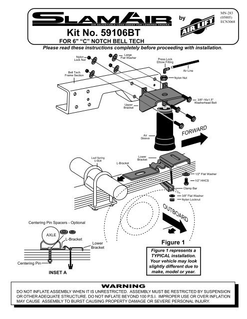
<strong>Kit</strong> No. <strong>59106BT</strong><br />
FOR 6" “C” NOTCH BELL TECH<br />
Please read these instructions completely before proceeding with installation.<br />
by<br />
MN-283<br />
(05005)<br />
ECN3068<br />
Nylon<br />
Lock Nut<br />
Large<br />
Flat Washer<br />
Press Lock<br />
Elbow Fitting<br />
Bell Tech<br />
Frame Section<br />
Nylon Nut<br />
<strong>Air</strong> Line<br />
Upper<br />
Bracket<br />
3/8"-16x1.5"<br />
Washerhead Bolt<br />
<strong>Air</strong><br />
Sleeve<br />
FORWARD<br />
Leaf Spring<br />
U-Bolt<br />
L-Bracket<br />
Lower<br />
Bracket<br />
Clamp Bar<br />
1/2" Flat Washer<br />
1/2" HHCS<br />
3/8" Flat Washer<br />
Nylon Locknut<br />
OUTBOARD<br />
Centering Pin Spacers - Optional<br />
Centering Pin<br />
AXLE<br />
INSET A<br />
L-Bracket<br />
Lower<br />
Bracket<br />
Figure 1<br />
Figure 1 represents a<br />
TYPICAL installation.<br />
Your vehicle may look<br />
slightly different due to<br />
make, model or year.<br />
WARNING<br />
DO NOT INFLATE ASSEMBLY WHEN IT IS UNRESTRICTED. ASSEMBLY MUST BE RESTRICTED BY SUSPENSION<br />
OR OTHER ADEQUATE STRUCTURE. DO NOT INFLATE BEYOND 100 P.S.I. IMPROPER USE OR OVER INFLATION<br />
MAY CAUSE ASSEMBLY TO BURST CAUSING PROPERTY DAMAGE OR SEVERE PERSONAL INJURY.
Please read these instructions completely before attempting the installation.<br />
This kit is designed to bolt onto the Bell Tech notched frame section through<br />
existing holes forward of the axle.<br />
RIDE HEIGHT:<br />
Ride height (no load)- This is the distance between the bottom of the bumper and a<br />
flat road surface with the vehicle in its “lowered” condition without anything in<br />
the bed of the truck. Take a measurement before installation and note it.<br />
This kit is designed to fit where the leaf springs are offset outboard of the frame<br />
rail. <strong>59106BT</strong> is a side mount kit– between the frame and tire. Due to the wide<br />
variety of lowering kits on the market, <strong>Air</strong> <strong>Lift</strong> cannot guarantee that this kit will<br />
fit every vehicle. You may need to modify the upper bracket, or even weld it,<br />
depending on the type of kit the vehicle was lowered with or optional equipment<br />
present. This will not void the warranty.<br />
Failure to maintain minimum air pressure of 10 p.s.i. in the air sleeve,<br />
bottoming out or over extension will void the warranty.<br />
Minimum<br />
of 5.0"<br />
Figure 2<br />
Before starting this installation, carefully<br />
measure the distance between the frame<br />
and inner part of the tire when vehicle is<br />
at normal height.<br />
IMPORTANT:<br />
Your vehicle may be equipped with a rear brake proportioning valve. Any type of<br />
load assist suspension product could affect brake performance. We recommend<br />
that you check with your dealer before installing this type of product. If your<br />
vehicle does not have a proportioning valve or is equipped with an anti-lock brake<br />
system, no adjustment or modification is required.<br />
REQUIRES MINIMUM CLEARANCE OF 5.0" BETWEEN TIRE AND<br />
FRAME (Figure 2).<br />
1. Jack up rear of vehicle or raise on hoist and remove rear wheels.<br />
2. Loosely attach the lower bracket to the sleeve using the 1/2" flat washer and<br />
1/2" HHCS bolt (Figure 1).<br />
3. Support frame and drop rear axle all the way until axle is hanging. If the<br />
shocks stop the axle from hanging remover lower shock bolts. Remove leaf<br />
spring retaining U-bolts on one side and, with a floor jack, raise axle to clear<br />
leaf spring centering pin leaf stack. A spacer is provided to accommodate the<br />
increased thickness caused by the lower bracket. Clamp the leaf spring<br />
together with a C-clamp so leaf center pin can be removed. Remove centering<br />
pin and install one spacer per pin. (NOTE: There are two different sizes, use<br />
the one that fits pin, discard other size.) Reinstall pin. If nut does not have full<br />
thread contact, replace centering pin. Set lower L-bracket on leaf, make sure<br />
centering pin goes through slot on L-bracket, drop axle down, and reinstall<br />
U-bolts. Slightly tighten U-bolts so that lower bracket can be adjusted later.<br />
Install L-bracket on other side in same manner. See Inset A and Figure 1 on<br />
front page.<br />
4. Simulate RIDE HEIGHT (see definition above) by raising the axle or lowering<br />
the frame (Figure1).<br />
IMPORTANT– In no case should the air sleeve be the suspension limiter<br />
in either extension or compression. Most vehicles will have a hard rubber<br />
compression stop on the rear suspension. The shock absorber is usually<br />
the limiter in full extension. The maximum extended length of the sleeve is<br />
11.5" and the minimum compressed height is 3.00".<br />
Sleeve diameter grows to 4.6" maximum at high pressure. Take this diameter into<br />
consideration when checking for possible interference in the mounting area.<br />
Failure to maintain minimum air pressure of 10 p.s.i. in the air sleeve,<br />
bottoming out or over extension will void the warranty.<br />
2
5. Install the air fitting finger tight plus two turns. Use a 7/16" open end<br />
wrench being careful to tighten on the metal hex nut only. DO NOT<br />
OVER TIGHTEN. This fitting is pre-coated with thread sealant.<br />
6. Assemble upper bracket onto the sleeve and tighten the mounting nut to<br />
4 ft-lbs.<br />
7. Attach lower bracket to the sleeve using 1/2" bolt and washer (Figure 1).<br />
Option 1<br />
Option 2<br />
Figure 3<br />
8. Set assembly on leaf spring with the “finger” of the lower bracket over the<br />
post of the “L” bracket mounted in step 3 (Figure 1). Insert U-bolt over<br />
bracket, slide lower clamp bar on U-bolt, attach with 3/8" nylon nut and flat<br />
washer. Leave loose for final adjustment (Figure 1).<br />
9. Install the upper bracket onto the notched section with the provided bolts,<br />
washers and locknuts, and tighten 20 ft-lbs. (Figure 1).<br />
10. Select a location for the inflation valves in the rear bumper area or rocker<br />
panel flange insuring that each valve will be protected and accessible with an<br />
air hose (Figure 3).<br />
11. Use a standard tube cutter, a razor blade, or a very sharp knife to cut the air<br />
line in two equal lengths. A clean square cut will ensure against leaks. Drill<br />
5/16" hole for inflation valve and mount as illustrated. Rubber washer on<br />
outside is for weather seal (Figure 4).<br />
CAUTION: LEAVE SUFFICIENT AIR LINE SLACK TO PREVENT ANY<br />
STRAIN ON VALVE STEM DURING NORMAL AXLE MOTIONS.<br />
12. Route air line along frame to desired inflation valve location (Figure 3).<br />
Attach air line to chassis with the provided plastic straps.<br />
TO PREVENT AIR LINE FROM MELTING, KEEP IT AT LEAST<br />
TWELVE INCHES FROM EXHAUST SYSTEM.<br />
13. Cut off excess air line squarely. Install the air line into the fitting. This is a self<br />
locking fitting. Push and slightly turn the cut end of the air line into the fitting<br />
as far as it will go. You will hear/feel a definite “click” when the air line is<br />
seated. The air line is now installed. <strong>Air</strong> line should go in approximately 3/4".<br />
14. Repeat process for right side.<br />
15. VERY IMPORTANT– With the bottom still loose, inflate the sleeve to<br />
approximately 10 p.s.i. By using the slotted adjustments in both brackets,<br />
align the sleeve so that there is a symmetrical cushion of air around the lower<br />
base of the sleeve to prevent side load wear. (Figure 6) Tighten the axle U-<br />
bolts to 45 ft-lbs. Tighten lower bracket U-bolt to 16 ft-lbs. Tighten the lower<br />
sleeve mounting bolt to 10 ft-lbs. (Figure 1)<br />
VEHICLE BODY<br />
OR BUMPER<br />
FLAT WASHER<br />
Figure 4<br />
AIR LINE<br />
TO BELLOWS<br />
STAR<br />
WASHER<br />
RUBBER WASHER<br />
16. Inflate to 30 p.s.i. Check all fittings and valve core with a soapy water<br />
solution for leaks. Check once again to be sure you have proper clearance<br />
around the sleeve. When the sleeve is inflated there must be sufficient<br />
clearance all around the sleeve.<br />
17. Recheck air pressure after 24 hours. A 2-4 p.s.i. loss after initial installation is<br />
normal. If pressure has dropped more than 5 lbs. re-test for leaks with soapy<br />
water solution. Please read and follow the Maintenance and Operation Tips.<br />
Check to see that the sleeve rolls back down over the bottom piston after the<br />
vehicle is lowered.<br />
3
FINISHED INSTALLATION<br />
NOT CORRECT<br />
MISALIGNED OR UNDER INFLATED<br />
(ok during assembly)<br />
FIGURE 6<br />
FAILURE TO MAINTAIN MINIMUM PRESSURE, BOTTOMING OUT, OR OVER<br />
EXTENSION WILL VOID THE WARRANTY.<br />
MINIMUM AIR PRESSURE<br />
10 P.S.I.<br />
MAINTENANCE/OPERATION<br />
4<br />
CORRECT FINISHED<br />
INSTALLATION<br />
(inflated)<br />
MAXIMUM AIR PRESSURE<br />
100 P.S.I.<br />
MAINTENANCE<br />
1. Check pressure weekly.<br />
2. Always maintain at least 10 p.s.i. air pressure to prevent chafing.<br />
3. If you develop an air leak in the system, use a soapy water solution to check all air line connections and the<br />
inflation valve core before removing sleeve.<br />
OPERATING TIPS<br />
1. Inflate your air springs to 60 p.s.i. before adding the payload. After vehicle is loaded, adjust your air pressure to<br />
level the vehicle and for ride comfort.<br />
2. When you are carrying a payload it will be helpful to increase the tire inflation pressure in proportion to any<br />
overload condition. We recommend a 2 p.s.i. increase above normal (not to exceed tire manufacturer maximum)<br />
for each 100 lbs. total overload on the axle.<br />
NOTE<br />
1. IMPORTANT: For your safety and to prevent possible damage to your vehicle, do not exceed maximum load<br />
recommended by the vehicle manufacturer. Although your air springs are rated at maximum inflation pressure of<br />
100 p.s.i., the air pressure actually needed is dependent on your load and GVWR, which may be less than 100<br />
p.s.i. Check your vehicle owner’s manual and do not exceed maximum load listed for your vehicle.<br />
When inflating your <strong>Air</strong> <strong>Lift</strong> sleeves, add pressure in small quantities, checking pressure frequently during<br />
inflation. The sleeves require much less air volume than a tire and therefore inflate much quicker.<br />
2. Should it become necessary to raise the vehicle by the frame, make sure the system is at minimum pressure<br />
(10 p.s.i.) to reduce the tension on suspension/brake components. Check to see that the sleeve rolls back<br />
down over the bottom piston after the vehicle is lowered (Figure 6). If sleeve fails to roll back down over the<br />
piston, add air pressure until sleeve “pops” back over piston (do not exceed 100 p.s.i.).<br />
Thank you for purchasing <strong>Air</strong> <strong>Lift</strong> Products<br />
AIR LIFT COMPANY<br />
P.O. BOX 80167<br />
LANSING MI 48908-0167<br />
FOR TECHNICAL ASSISTANCE CALL 1-800-248-0892<br />
Caution: DO NOT EXCEED THE VEHICLE MANUFACTURERS MAXIMUM GROSS VEHICLE WEIGHT RATING.


