

MSD 85821 Distributor Installation Instructions - Jegs
MSD 85821 Distributor Installation Instructions - Jegs
MSD 85821 Distributor Installation Instructions - Jegs

You also want an ePaper? Increase the reach of your titles
YUMPU automatically turns print PDFs into web optimized ePapers that Google loves.
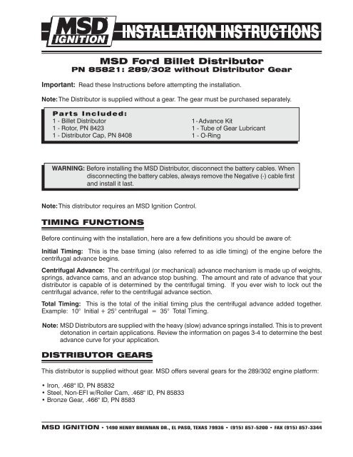
<strong>MSD</strong> Ford Billet <strong>Distributor</strong><br />
PN <strong>85821</strong>: 289/302 without <strong>Distributor</strong> Gear<br />
Important: Read these <strong>Instructions</strong> before attempting the installation.<br />
Note: The <strong>Distributor</strong> is supplied without a gear. The gear must be purchased separately.<br />
Parts Included:<br />
1 - Billet <strong>Distributor</strong><br />
1 - Rotor, PN 8423<br />
1 - <strong>Distributor</strong> Cap, PN 8408<br />
1 - Advance Kit<br />
1 - Tube of Gear Lubricant<br />
1 - O-Ring<br />
WARNING: Before installing the <strong>MSD</strong> <strong>Distributor</strong>, disconnect the battery cables. When<br />
disconnecting the battery cables, always remove the Negative (-) cable first<br />
and install it last.<br />
Note: This distributor requires an <strong>MSD</strong> Ignition Control.<br />
TIMING FUNCTIONS<br />
Before continuing with the installation, here are a few definitions you should be aware of:<br />
Initial Timing: This is the base timing (also referred to as idle timing) of the engine before the<br />
centrifugal advance begins.<br />
Centrifugal Advance: The centrifugal (or mechanical) advance mechanism is made up of weights,<br />
springs, advance cams, and an advance stop bushing. The amount and rate of advance that your<br />
distributor is capable of is determined by the centrifugal timing. If you ever wish to lock out the<br />
centrifugal advance, refer to the centrifugal advance section.<br />
Total Timing: This is the total of the initial timing plus the centrifugal advance added together.<br />
Example: 10° Initial + 25° centrifugal = 35° Total Timing.<br />
Note: <strong>MSD</strong> <strong>Distributor</strong>s are supplied with the heavy (slow) advance springs installed. This is to prevent<br />
detonation in certain applications. Review the information on pages 3-4 to determine the best<br />
advance curve for your application.<br />
DISTRIBUTOR GEARS<br />
This distributor is supplied without gear. <strong>MSD</strong> offers several gears for the 289/302 engine platform:<br />
• Iron, .468" ID, PN 85832<br />
• Steel, Non-EFI w/Roller Cam, .468" ID, PN 85833<br />
• Bronze Gear, .466" ID, PN 8583<br />
<strong>MSD</strong> IGNITION • 1490 HENRY BRENNAN DR., EL PASO, TEXAS 79936 • (915) 857-5200 • FAX (915) 857-3344
INSTALLATION INSTRUCTIONS<br />
GEAR INSTALLATION<br />
It is recommended to have a reputable machine shop install the gear. The installation process requires<br />
a press fit and the need for special tools to achieve proper installation without damaging the shaft,<br />
gear or housing.<br />
CAUTION: If the gear is installed improperly, severe damage to the distributor and/or engine block<br />
will occur!<br />
1. With the endplay of the distributor shaft removed, measure the distance from the bottom of the gear<br />
to the bottom of the mounting flange (Figure 1). It should be within the specifications shown.<br />
2. Press the new gear into position on the shaft. Measure the distance as shown in Figure 1 before<br />
drilling the new roll pin hole.<br />
3. Carefully drill a 0.125” hole through the shaft using the gear as a guide.<br />
4. Install the new 1/8” spiral roll pin.<br />
Thrust Collar<br />
Press firmly<br />
to take out<br />
all end play<br />
before measuring.<br />
4.005" Max.<br />
3.996" Min.<br />
Figure 1 Gear <strong>Installation</strong> Specifications.<br />
<strong>MSD</strong> IGNITION • 1490 HENRY BRENNAN DR., EL PASO, TEXAS 79936 • (915) 857-5200 • FAX (915) 857-3344
INSTALLATION INSTRUCTIONS<br />
<br />
CHOOSING AN ADVANCE CURVE<br />
The function of the advance curve is to match the ignition timing to the burning rate of the fuel and<br />
speed (rpm) of the engine. Any factor that changes the burning rate of the fuel or the engine speed<br />
can cause a need for an ignition timing change. Figure 2 shows some of the factors that will affect<br />
engine timing.<br />
FACTOR Advance Timing Retard Timing<br />
For<br />
For<br />
Cylinder Pressure Low High<br />
Vacuum High Low<br />
Energy of Ignition Low High<br />
Fuel Octane High Low<br />
Mixture (Air/Fuel) Rich Lean<br />
Temperature Cool Hot<br />
Combustion Chamber Shape Open Compact<br />
Spark Plug Location Offset Center<br />
Combustion Turbulence Low High<br />
Load Light Heavy<br />
Figure 2 Ignition Timing Factors.<br />
As you can see from the chart, most factors will change throughout the range of the engine operation.<br />
The timing mechanism of the distributor must make timing changes based on these factors.<br />
Example: An engine has 11:1 compression with a high energy ignition. With the specifications given,<br />
you will have to retard the timing for the high compression and high energy ignition. By comparing<br />
the engine’s specifications against the chart, a usable timing guideline can be found. Engines with<br />
a combination of items from both columns will require a timing that is set in the mid range.<br />
Obviously a full technical explanation of correct ignition timing would be very complicated. The best<br />
way to arrive at a suitable ignition curve for your engine is to use the Ignition Timing Factors Chart<br />
as a guide and compare it to the Advance Graphs in Figure 5 until a suitable curve is found. When<br />
selecting your advance curve, use detonation (engine ping) as an indicator of too much advance,<br />
and a decrease in power as an indicator of too little advance.<br />
Tips on Selecting an Advance Curve<br />
• Use as much initial advance as possible without encountering excessive starter load.<br />
• Start the centrifugal advance just above the idle rpm.<br />
• The starting point of the centrifugal advance curve is controlled by the installed length and<br />
tension of the spring.<br />
• How quickly the centrifugal advance (slope) comes in is controlled by the spring stiffness.<br />
The stiffer the spring, the slower the advance curve.<br />
• The amount of advance is controlled by the advance bushing. The bigger the bushing, the<br />
smaller the amount of advance.<br />
<strong>MSD</strong> IGNITION • 1490 HENRY BRENNAN DR., EL PASO, TEXAS 79936 • (915) 857-5200 • FAX (915) 857-3344
INSTALLATION INSTRUCTIONS<br />
CENTRIFUGAL ADVANCE CURVE<br />
Selecting the Advance<br />
Springs<br />
The rate, or how quick the advance comes<br />
in is determined by the type of springs which<br />
are installed on the distributor. The <strong>MSD</strong><br />
distributors are equipped with two Heavy<br />
Silver springs installed. These will give you<br />
the slowest advance curve possible (Figure<br />
3). The parts kit contains two additional sets<br />
of springs which can be used to match the<br />
advance curve to your particular application.<br />
Refer to the Spring Combination Chart<br />
(Figure 4) for combinations that can be<br />
achieved.<br />
To change the springs, remove the cap and<br />
rotor and use needlenose pliers to remove<br />
the springs. Be sure the new springs seat<br />
in the groove on the pin.<br />
Timing Curve From Factory<br />
Figure 3 The Factory Equipped Curve.<br />
SPRING COMBINATION RATE OF ADVANCE FIGURE 4<br />
2- Heavy Silver SLOWEST A<br />
1- Heavy Silver B<br />
1- Light Blue<br />
1-Heavy Silver<br />
C<br />
1-Light Silver<br />
2- Light Blue D<br />
1- Light Silver E<br />
1- Light Blue<br />
2- Light Silver FASTEST F<br />
Figure 4 Spring Combination Chart.<br />
Figure 5 Advance Curves.<br />
<strong>MSD</strong> IGNITION • 1490 HENRY BRENNAN DR., EL PASO, TEXAS 79936 • (915) 857-5200 • FAX (915) 857-3344
INSTALLATION INSTRUCTIONS<br />
<br />
Selecting the Advance Stop<br />
Bushing<br />
Three different advance stop bushings are supplied<br />
in the distributor kit. The distributor comes with a<br />
Blue (21°) bushing already installed. If a different<br />
amount of centrifugal advance is desired, follow the<br />
next procedure to change the bushings. The chart<br />
in Figure 6 gives the size and approximate degrees<br />
for the corresponding bushings.<br />
BUSHING SIZE APPROXIMATE<br />
CRANKSHAFT<br />
DEGREES<br />
Red-Smallest 28<br />
Silver 25<br />
Blue 21<br />
Black-Largest 18<br />
Figure 6 Advance Stop Bushing Chart.<br />
Changing the Advance Stop<br />
Bushings<br />
1. Remove the distributor cap and rotor.<br />
2. Remove the locknut and washer on the bottom<br />
of the advance assembly (Figure 7).<br />
3. Remove the bushing and install the new one.<br />
Install the washer and locknut.<br />
Locking Out the Centrifugal<br />
Advance<br />
1. Remove the advance components including the<br />
springs, weights and the advance stop bushing<br />
from the advance assembly.<br />
2. Remove the roll-pin from the shaft retaining<br />
sleeve and slide the shaft up.<br />
3. Rotate the shaft 180° and insert the advance stop<br />
bushing pin into the small hole on the advance<br />
plate (Figure 8).<br />
4. Install the locknut and washer to the advance<br />
stop bushing pin. This locks the advance in<br />
place.<br />
5. Install the retaining sleeve and its roll-pin.<br />
Figure 7 Changing the Advance Stop Bushing.<br />
Figure 6 Locking Out the Centrifugal Advance.<br />
Figure 8 Locking Out the Advance.<br />
<strong>MSD</strong> IGNITION • 1490 HENRY BRENNAN DR., EL PASO, TEXAS 79936 • (915) 857-5200 • FAX (915) 857-3344
INSTALLATION INSTRUCTIONS<br />
INSTALLING THE DISTRIBUTOR<br />
1. Remove the existing distributor cap without<br />
disconnecting any of the spark plug wires.<br />
2. With the cap off, crank the engine until the rotor is<br />
aimed at a fixed point on the engine or firewall. Note<br />
this position by making a mark (Figure 9).<br />
3. Place the distributor cap back on and note which<br />
plug wire the rotor is pointing to. MARK THE<br />
SPARK PLUG WIRES and remove the distributor<br />
cap.<br />
4. Disconnect the wiring from the distributor.<br />
5. Loosen the distributor hold down clamp and slide<br />
the clamp out of the way.<br />
6. Lift the distributor out of the engine. Note that the<br />
rotor rotates as you lift the distributor out. This is<br />
due to the helical cut gear and should be taken into<br />
consideration when installing the new distributor.<br />
Figure 9 Marking the Rotor Location.<br />
7. Install the new O-ring and apply a liberal amount<br />
of the supplied lubricant to the distributor gear.<br />
8. Install the distributor making sure that the rotor comes to rest pointing at the fixed mark. If the distributor<br />
will not fully seat with the rotor pointing to the marked position, you may need to rotate the oil pump<br />
shaft until the rotor lines up and the distributor fully seats.<br />
9. Position and tighten the hold down clamp onto the distributor.<br />
10. Install the distributor cap and spark plug wires one at a time to ensure correct location.<br />
WARNING: High voltage is present on the coil terminals. Do not touch the terminals or<br />
coil tower when the engine is cranking or running.<br />
TO 12V<br />
IGNITION KEY<br />
FROM<br />
IGNITION KEY<br />
(ORIGINAL COIL WIRE)<br />
+<br />
TO BATTERY<br />
TO BATTERY<br />
+<br />
HEAVY RED<br />
HEAVY BLACK<br />
RED<br />
WHITE (NOT USED)<br />
ORANGE<br />
BLACK<br />
+<br />
®<br />
TACH<br />
OUTPUT<br />
IGNITION<br />
Multiple<br />
Spark<br />
Discharge<br />
AUTOTRONIC CONTROLS CORPORATION<br />
PART NO.<br />
SERIAL NO..<br />
GREEN<br />
PN 8860 HARNESS<br />
VIOLET<br />
Figure 10 Wiring to an <strong>MSD</strong> 6-Series Ignition Control.<br />
<strong>MSD</strong> IGNITION • 1490 HENRY BRENNAN DR., EL PASO, TEXAS 79936 • (915) 857-5200 • FAX (915) 857-3344
7200<br />
INSTALLATION INSTRUCTIONS<br />
<br />
PRO POWER COIL<br />
+<br />
TO 12V<br />
HEAVY BLACK<br />
TO BATTERY<br />
ORANGE<br />
BLACK<br />
IGNITION<br />
KEY<br />
FROM<br />
IGNITION KEY<br />
(ORIGINAL COIL WIRE)<br />
+<br />
HEAVY RED<br />
TO BATTERY +<br />
C+<br />
C-<br />
RED<br />
GROUND<br />
RPM<br />
T<br />
A<br />
C<br />
H<br />
IGN<br />
PTS<br />
M+<br />
M-<br />
WHITE (NOT USED)<br />
VIOLET<br />
GREEN PN 8860<br />
HARNESS<br />
VIOLET<br />
GREEN<br />
Figure 11 Wiring to an <strong>MSD</strong> 7-Series Ignition Control.<br />
HEAVY RED<br />
TO BATTERY<br />
HEAVY BLACK +<br />
TO BATTERY<br />
+<br />
ORANGE<br />
T<br />
A<br />
C<br />
H<br />
C+<br />
C-<br />
IGN<br />
PTS<br />
M+<br />
M-<br />
NOT<br />
USED<br />
RED<br />
BLACK<br />
SWITCHED 12 VOLTS<br />
FROM IGNITION KEY<br />
NOT USED<br />
WHITE<br />
GREEN<br />
TIMING<br />
CONTROL<br />
WHITE<br />
YELLOW<br />
RED<br />
VIOLET<br />
TO GROUND<br />
Note: <strong>MSD</strong> 6 and 7 Series Ignitions<br />
share the same color wiring.<br />
Figure 12 Wiring with an <strong>MSD</strong> 7-Series Ignition and Timing Control.<br />
<strong>MSD</strong> IGNITION • 1490 HENRY BRENNAN DR., EL PASO, TEXAS 79936 • (915) 857-5200 • FAX (915) 857-3344
NOTES<br />
Service<br />
In case of malfunction, this <strong>MSD</strong> component will be repaired free of charge according to the terms<br />
of the warranty. When returning <strong>MSD</strong> components for service, Proof of Purchase must be supplied for<br />
warranty verification. After the warranty period has expired, repair service is charged based on a minimum<br />
and maximum charge.<br />
All returns must have a Return Material Authorization (RMA) number issued to them before being<br />
returned. To obtain an RMA number please contact <strong>MSD</strong> Customer Service at (915) 855-7123 or fax a<br />
request to (915) 857-3344. Send the unit prepaid with proof of purchase to the attention of: <strong>MSD</strong> Ignition,<br />
Customer Service - RMA #, 12120 Esther Lama, Dock 5, El Paso, Texas 79936.<br />
When returning the unit for repair, leave all wires at the length in which you have them installed. Be<br />
sure to include a detailed account of any problems experienced, and what components and accessories<br />
are installed on the vehicle.<br />
The repaired unit will be returned as soon as possible after receipt, COD for any charges. (Ground<br />
shipping is covered by warranty). All units are returned regular UPS unless otherwise noted. For more<br />
information, call the <strong>MSD</strong> Customer Service Line (915) 855-7123. <strong>MSD</strong> technicians are available from<br />
7:00 a.m. to 6:00 p.m. Monday - Friday (mountain time).<br />
Limited Warranty<br />
<strong>MSD</strong> IGNITION warrants <strong>MSD</strong> Ignition products to be free from defects in material and workmanship<br />
under normal use and if properly installed for a period of one year from date of purchase. If found to be<br />
defective as mentioned above, it will be replaced or repaired if returned prepaid along with proof of date of<br />
purchase. This shall constitute the sole remedy of the purchaser and the sole liability of <strong>MSD</strong> Ignition. To<br />
the extent permitted by law, the foregoing is exclusive and in lieu of all other warranties or representations<br />
whether expressed or implied, including any implied warranty of merchantability or fitness. In no event<br />
shall <strong>MSD</strong> Ignition be liable for special or consequential damages.<br />
<strong>MSD</strong> IGNITION • 1490 HENRY BRENNAN DR., EL PASO, TEXAS 79936 • (915) 857-5200 • FAX (915) 857-3344<br />
© 2006 Autotronic Controls Corporation<br />
FRM27618 Created 04/06 Printed in U.S.A.


