

MSD 7AL-3, Ignition Control
MSD 7AL-3, Ignition Control
MSD 7AL-3, Ignition Control

Create successful ePaper yourself
Turn your PDF publications into a flip-book with our unique Google optimized e-Paper software.
<strong>MSD</strong> <strong>7AL</strong>-3, <strong>Ignition</strong> <strong>Control</strong><br />
PN 7330<br />
ONLINE PRODUCT REGISTRATION: Register your <strong>MSD</strong> product online. Registering your<br />
product will help if there is ever a warranty issue with your product and helps the <strong>MSD</strong> R&D<br />
team create new products that you ask for! Go to www.msdperformance.com/registration.<br />
Important: Read the instructions before attempting the installation.<br />
Parts Included:<br />
1 - <strong>7AL</strong>-3, PN 7330<br />
1 - Parts Bag (wires and connectors)<br />
4 - RPM Modules 3000, 7000, 8000, 9000<br />
4 - Retard Modules 2°, 3°, 4°, 5°, 10°, 15° and 20°<br />
4 - Zero Degree Modules<br />
4 - Vibration Mounts<br />
WARNING: During installation, disconnect the battery cables. When disconnecting the battery,<br />
always remove the Negative cable first and install it last.<br />
Note: The <strong>MSD</strong> <strong>7AL</strong>-3 will retard the ignition timing approximately 4° compared to other <strong>MSD</strong> <strong>Ignition</strong>s.<br />
After installation, the timing should always be checked and adjusted at idle and total timing.<br />
COIL RECOMMENDATIONS<br />
The <strong>MSD</strong> <strong>7AL</strong>-3 can be used with a variety of coils, but to receive the best performance, it is<br />
recommended to use an <strong>MSD</strong> Coil. For drag racing and “short duration” applications, the Pro Power<br />
Coil, PN 8201. For street applications or long duration racing events, the HVC Pro Power Coil, PN<br />
8251 or PN 8261 are recommended. The <strong>7AL</strong>-3 may be used with a GM HEI Distributor with an internal<br />
coil, however the Rotor Bushing must be replaced with an <strong>MSD</strong> Low Resistance Bushing, PN 8412.<br />
MOUNTING<br />
The <strong>7AL</strong>-3 can be mounted under the hood, but should be mounted in a position away from direct<br />
engine heat sources. Use the ignition as a template and mark the location of the mounting holes.<br />
Remove the unit and drill the holes using a 1/4" bit. Install the vibration mounts to the <strong>7AL</strong>-3 then<br />
mount the ignition using the supplied lock washers<br />
and nuts.<br />
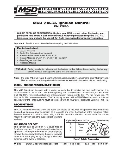
Cylinders Loops to Cut Remove cap<br />
CYLINDER SELECT<br />
This ignition can be used on 4, 6 (even-fire) or<br />
8-cylinder engines. The ignition is set for 8-cylinder<br />
operation. To program the unit for other engines,<br />
remove the one screw that holds the cover to reveal<br />
three wire loops (Figure 1). Cutting a wire loop<br />
determines the cylinder selection.<br />
8 None<br />
6 One<br />
4 Two<br />
Cut loops<br />
Figure 1 Cylinder Programming.<br />
M S D • W W W . M S D P E R F O R M A N C E . C O M • ( 9 1 5 ) 8 5 7 - 5 2 0 0 • F A X ( 9 1 5 ) 8 5 7 - 3 3 4 4
2 INSTALLATION INSTRUCTIONS<br />
WIRING<br />
Wiring the <strong>7AL</strong>-3 will be simple by following the instructions. There are several color coded wires<br />
supplied with the <strong>7AL</strong>-3 and should be used as noted to avoid confusion or wrong connections. This<br />
section is also broken down into two sections; Primary Wiring and Optional Wiring.<br />
• The Primary section designates the wires that must be connected to run the engine.<br />
• The Optional Wiring section explains the wiring of optional built-in features such as the Rev <strong>Control</strong>s,<br />
RPM Activated Switch and Retard <strong>Control</strong>s. This information starts on page 6.<br />
WARNING: The <strong>7AL</strong>-3 produces very high voltages. Never short the battery or coil terminals. Use<br />
caution during installation and while working near the ignition.<br />
PRIMARY WIRING<br />
1. Begin wiring the <strong>MSD</strong> by connecting the wires responsible to run the engine. The terminal strip on<br />
the left side of the box is responsible for the Power Leads and the Coil Wires. Connect the supplied<br />
wires as follows:<br />
Heavy Red: Connect from the “Batt +” terminal directly to the battery positive (+) terminal.<br />
Heavy Black: Connect from the “Batt -” terminal directly to the battery negative (-) terminal.<br />
Orange: Connect from the “Coil +” terminal to the positive terminal (+) of the coil (570V).<br />
Black: Connect from the “Coil -” terminal to the negative terminal (-) of the coil (Ground).<br />
2. Move to the middle terminal strip and locate the terminal marked “<strong>Ignition</strong>”. Use the supplied RED<br />
wire and connect it to a switched 12 volt source (ignition switch).<br />
3. If a retard function is not going to be used the supplied "zero" degree module must be installed.<br />
See the Multi-Step Retard Section.<br />
4. The three terminals on the bottom of the middle terminal strip receive the trigger signal from the<br />
distributor. One terminal is for points style applications and the other two are for use with a magnetic<br />
pickup trigger, such as an <strong>MSD</strong> Billet Distributor or Crank Trigger.<br />
Note: The Points and Mag Pickup terminals will never be connected at the same time.<br />
Points: If you are using a Points style distributor or electronic amplifier, only the “Points” terminal<br />
will be used. Connect the supplied WHITE wire from the points output in the distributor to the “Pnts”<br />
terminal (Figure 1).<br />
Magnetic Pickup: If you are using an <strong>MSD</strong> Distributor or Crank Trigger, only the Magnetic Pickup<br />
terminals will be used. Locate the supplied harness with a VIOLET and GREEN wire with a 2-pin<br />
connector on one end. Connect the VIOLET wire to the<br />
“Mag +” terminal and the GREEN wire to the “Mag -”<br />
terminal then connect the 2-pin connector to the Distributor<br />
(Figure 1).<br />
Magnetic Pickup Polarity<br />
The <strong>MSD</strong> <strong>7AL</strong>-3 can be used with other magnetic pick-up<br />
distributors as long as the wires are connected correctly.<br />
The chart on the right shows the polarity of some common<br />
magnetic pickups.<br />
Common Mag Pickup Wires<br />
Distributor<br />
Colors<br />
Mag+ Mag-<br />
<strong>MSD</strong> Org/Blk Vio/Blk<br />
<strong>MSD</strong> Crank Trigger Violet Green<br />
Ford Orange Purple<br />
Accel 46/48000 Series Org/Blk Vio/Blk<br />
Accel 51/61000 Series Red Black<br />
Chrysler Org/Wht Black<br />
Mallory Org/Blk Vio/Blk<br />
Figure 1<br />
M S D • W W W . M S D P E R F O R M A N C E . C O M • ( 9 1 5 ) 8 5 7 - 5 2 0 0 • F A X ( 9 1 5 ) 8 5 7 - 3 3 4 4
INSTALLATION INSTRUCTIONS 3<br />
NOTE: THE POINTS AND MAG PICKUP<br />
WIRES WILL NEED TO BE CONNECT-<br />
ED AT THE SAME TIME.<br />
Figure 2 Wiring the Primary Side of the <strong>Ignition</strong> to Points or Magnetic Pickup.<br />
ORANGE (+)<br />
BLACK (-)<br />
OUTPUT<br />
RAS<br />
IGN<br />
RAS<br />
ON/OFF<br />
RET #1<br />
RED<br />
RED<br />
COIL<br />
NOTE: THIS DIAGRAM<br />
ILLUSTRATES HOW TO<br />
INSTALL AN <strong>MSD</strong><br />
TIMING CONTROL.<br />
COIL +<br />
TACH<br />
RET #2<br />
COIL -<br />
START<br />
RETARD<br />
RET #3<br />
YELLOW<br />
PNTS<br />
RET #4<br />
BATT -<br />
M+<br />
BURNOUT<br />
BATT +<br />
M-<br />
LAUNCH<br />
TO BATTERY<br />
POSITIVE<br />
TO BATTERY<br />
NEGATIVE<br />
RETARD<br />
1 2<br />
0 3<br />
WHITE<br />
NOT USED<br />
DISTRIBUTOR<br />
WITH<br />
MAGNETIC PICKUP<br />
<strong>MSD</strong><br />
DISTRIBUTOR<br />
GREEN<br />
VIOLET<br />
OR<br />
<strong>MSD</strong> CRANK<br />
TRIGGER WHEEL<br />
MAGNETIC PICKUP<br />
CONNECTOR<br />
Figure 3 Primary Wiring to an <strong>MSD</strong> Timing or Boost <strong>Control</strong> and a Magnetic Pickup.<br />
M S D • W W W . M S D P E R F O R M A N C E . C O M • ( 9 1 5 ) 8 5 7 - 5 2 0 0 • F A X ( 9 1 5 ) 8 5 7 - 3 3 4 4
4 INSTALLATION INSTRUCTIONS<br />
RAS<br />
ON/OFF<br />
<strong>MSD</strong><br />
READY-TO-RUN<br />
DISTRIBUTOR<br />
Figure 4 Primary Wiring to an <strong>MSD</strong> Ready-to-Run Distributor.<br />
RAS<br />
ON/OFF<br />
NOTE: ALL 3-WIRE MALLORY DISTRIBUTORS CONNECT THIS WAY.<br />
Figure 5 Primary Wiring to a Mallory Unilite Distributor.<br />
Note: The <strong>MSD</strong> <strong>7AL</strong>-3 will retard the ignition timing approximately 4° compared to other <strong>MSD</strong> <strong>Ignition</strong>s.<br />
After installation, the timing should always be checked and adjusted at idle and total timing.<br />
M S D • W W W . M S D P E R F O R M A N C E . C O M • ( 9 1 5 ) 8 5 7 - 5 2 0 0 • F A X ( 9 1 5 ) 8 5 7 - 3 3 4 4
RED<br />
INSTALLATION INSTRUCTIONS 5<br />
GM HEI DISTRIBUTOR<br />
The <strong>7AL</strong>-3 can be wired to the GM HEI Distributor. You must identify which module your distributor<br />
has to determine which wiring diagram to use. Count the number of pins or terminals on the module<br />
and follow the diagram for a 4-pin or 7-pin module.<br />
NOTE:MODULE AND WIRING<br />
NEEDS TO BE REMOVED.<br />
NOTE: A LOW RESISTANCE HEI ROTOR<br />
BUSHING, PN 8412, MUST BE USED<br />
WITH AN <strong>MSD</strong> <strong>7AL</strong>-3 IGNITION.<br />
TO ENGINE OR<br />
CHASSIS GROUND<br />
WHITE<br />
JUMPER<br />
4-PIN MODULE<br />
ORANGE<br />
BLACK<br />
KEY<br />
CONNECTOR<br />
COIL +<br />
COIL -<br />
BATT -<br />
BATT +<br />
OUTPUT<br />
RAS<br />
IGN<br />
TACH<br />
START<br />
RETARD<br />
PNTS<br />
M+<br />
M-<br />
RAS<br />
ON/OFF<br />
RET #1<br />
RET #2<br />
RET #3<br />
RET #4<br />
BURNOUT<br />
LAUNCH<br />
RED<br />
VIOLET M+<br />
GREEN M-<br />
ORANGE<br />
BLACK<br />
18" BLK<br />
HEAVY RED<br />
OR PINK WIRE<br />
FROM CAR<br />
WIRING HARNESS<br />
PN 8861 HARNESS<br />
(THIS HARNESS IS AVAILABLE FROM <strong>MSD</strong>)<br />
TO BATTERY<br />
POSITIVE<br />
TO BATTERY<br />
NEGATIVE<br />
Figure 6 Primary Wiring to a GM HEI with a 4-Pin Module (Magnetic Pickup Trigger).<br />
RAS<br />
ON/OFF<br />
Figure 7 Primary Wiring to a GM HEI with a 5 or 7-Pin Module (Points Trigger).<br />
M S D • W W W . M S D P E R F O R M A N C E . C O M • ( 9 1 5 ) 8 5 7 - 5 2 0 0 • F A X ( 9 1 5 ) 8 5 7 - 3 3 4 4
6 INSTALLATION INSTRUCTIONS<br />
OPTIONAL WIRING<br />
This Wiring Section details the optional features of the <strong>MSD</strong> <strong>7AL</strong>-3 and<br />
how to wire each system.<br />
START RETARD<br />
The Start Retard of the <strong>7AL</strong>-3 is designed to ease cranking on engines<br />
with locked timing, high compression and a lot of advance. The amount<br />
of retard is determined by a plug-in degree module (Figure 8). There<br />
are two different ways to activate this function (Figure 9):<br />
A. Switched 12 Volts<br />
In this set up, the timing is retarded only while the engine is cranking.<br />
Connect the supplied Violet wire from the “Start-Retard” terminal on<br />
the <strong>7AL</strong>-3 to the starter solenoid. This way, 12 volts is only applied<br />
when the key or switch is in the cranking position. When the switch<br />
is released, 12 volts is removed and the timing returns to run timing.<br />
B. Constant 12 Volts<br />
In this setup, whenever the ignition is turned On, 12 volts is applied<br />
and the retard function is activated. The retard will be removed when<br />
the engine reaches about 600 rpm<br />
and will not occur again until the<br />
ignition is turned Off. Connect the<br />
RAS<br />
supplied jumper from the Start-<br />
ON/OFF<br />
Retard terminal to the IGN terminal<br />
of the terminal strip (two terminals<br />
up).<br />
RPM ACTIVATED<br />
SWITCH<br />
HIGH SPEED TIMING RETARD<br />
4500<br />
8°<br />
Zero Zero Zero<br />
Zero<br />
START<br />
#1 #2 #3 #4<br />
REV LIMITER<br />
<strong>7AL</strong>-3 SIDE VIEW<br />
START RETARD PLUG-IN<br />
DEGREE MODULE<br />
RAS<br />
ON/OFF<br />
7600 5800 4000<br />
RACE<br />
BURNOUT LAUNCH<br />
Figure 8 Side View of 7 AL-3<br />
THREE STEP RPM LIMITS<br />
The <strong>7AL</strong>-3 has a built-in Three Step<br />
Module Selector which allows you<br />
to select up to three different rpm<br />
limits. The activation terminals<br />
are located on the bottom of the<br />
third terminal strip and are listed<br />
as Launch and Burnout. The third<br />
rpm limit is the high rpm, which is<br />
always active when there is an rpm<br />
module installed in the "Race" holder<br />
(except when the other rpm limits are<br />
activated).<br />
These modules can be used in a variety<br />
of functions and are not limited to<br />
launches and burnouts. Each of the two<br />
optional rpm limits are activated when 12<br />
volts is applied to their corresponding<br />
terminals (Figure 10). The 12 volts can<br />
come from switches, solenoids or relays<br />
giving you a variety of ways to activate<br />
the different rpm limits. The following<br />
steps illustrate a general drag race<br />
installation for use with a Burnout limit,<br />
Launch limit and Race limit.<br />
Figure 9 Wiring the Start Retard Function.<br />
M S D • W W W . M S D P E R F O R M A N C E . C O M • ( 9 1 5 ) 8 5 7 - 5 2 0 0 • F A X ( 9 1 5 ) 8 5 7 - 3 3 4 4<br />
RAS<br />
ON/OFF<br />
Figure 10 Connecting the Three Step Module Selector.
INSTALLATION INSTRUCTIONS 7<br />
Burnout Rev Limit:<br />
Connect the supplied Blue wire from the Burnout terminal of the <strong>MSD</strong> to the 12 volt activation wire of<br />
the line lock solenoid. With this setup, when the line lock is activated, 12 volts will be supplied to the<br />
Burnout terminal which limits the rpm to your specified burnout rpm module.<br />
Launch Rev Limit:<br />
Connect the supplied Light Green wire to the Launch terminal of the <strong>MSD</strong> then splice it into the clutch<br />
or trans brake 12 volt activation wire. This way, when the clutch pedal is depressed, 12 volts is applied<br />
to the Launch terminal which limits the rpm to your specified launch rpm module.<br />
Note: The Launch rpm limit is designed to override the Burnout limit. This way, if you activate the<br />
line-lock on the starting line, when the Launch terminal is activated through the trans brake or<br />
clutch switch, the Launch rpm (not the Burnout limit) will be in effect. After the car launchs the<br />
Race rpm limit is activated to protect the engine from over revving.<br />
RPM ACTIVATED SWITCH<br />
The RPM Activated Switch (RAS) Output will turn on<br />
a component such as a shift light or nitrous solenoid<br />
at an adjustable rpm point by supplying a ground<br />
path (Figure 11). The RPM Switch is capable of<br />
handling a 10 amp load. If 12 volts is required to<br />
activate the component, use an <strong>MSD</strong> Relay, PN<br />
8960 or PN 8961.<br />
The <strong>7AL</strong>-3 also features an "RAS On/Off" for the RPM<br />
Activated Switch. To use the RPM Switch, 12 volts<br />
must be connected to the “RAS-On/Off” terminal<br />
located at the top of the third terminal strip. Whenever<br />
the 12 volts is removed from this terminal, the<br />
RPM Activated Switch will not operate. This is a<br />
useful feature for only turning on a nitrous solenoid<br />
in high gear<br />
by incorporating<br />
a switch<br />
on the shifter<br />
(Figure 12).<br />
RAS<br />
ON/OFF<br />
Figure 11 Connecting the RPM Activated Switch.<br />
NITROUS<br />
SOLENOID(S)<br />
WIRE (+)<br />
TWO STEP WIRE<br />
TRANS<br />
BRAKE<br />
12V<br />
GROUND<br />
RPM ACTIVATED<br />
SWITCH<br />
HIGH SPEED TIMING RETARD<br />
4500<br />
8°<br />
Zero Zero Zero<br />
Zero<br />
START<br />
#1 #2 #3 #4<br />
REV LIMITER<br />
7600 5800 4000<br />
RACE<br />
BURNOUT LAUNCH<br />
SWITCH<br />
INDICATES CONNECTION<br />
BATTERY<br />
12 V<br />
GROUND<br />
PUSH BUTTON<br />
<strong>7AL</strong>-3 SIDE VIEW<br />
Figure 12 Turning on Nitrous with R.A.S. after Transbrake is released.<br />
M S D • W W W . M S D P E R F O R M A N C E . C O M • ( 9 1 5 ) 8 5 7 - 5 2 0 0 • F A X ( 9 1 5 ) 8 5 7 - 3 3 4 4
8 INSTALLATION INSTRUCTIONS<br />
GROUND<br />
GROUND<br />
Figure 13 Wiring the RAS to activate a Plunger Style Shifter (12V input).<br />
GROUND<br />
GROUND<br />
Figure 14 Using the RAS to Activate a Shift Solenoid (takes away 12V power).<br />
M S D • W W W . M S D P E R F O R M A N C E . C O M • ( 9 1 5 ) 8 5 7 - 5 2 0 0 • F A X ( 9 1 5 ) 8 5 7 - 3 3 4 4
INSTALLATION INSTRUCTIONS 9<br />
MULTI-STEP RETARD<br />
There are four retard modules available with the <strong>7AL</strong>-3. Each module is activated independently by<br />
supplying 12 volts on the terminal from the corresponding module. The controlling terminals are listed<br />
as RET-1 through RET-4 and are located on the third terminal strip. The modules can be activated in<br />
any order and are cumulative unless deactivated. The maximum amount of retard allowed is a total<br />
of 20° even if the modules add up to more than 20°.<br />
Note: If a Retard function is not going to be used it is recommended to install a "zero" degree module.<br />
See page 12 for more module part numbers.<br />
RETARD WITH THE RPM ACTIVATED SWITCH<br />
The <strong>MSD</strong> <strong>7AL</strong>-3 has both an RPM Activated Switch (RAS) and a Multi-Step Retard. The stages of<br />
retard are activated when the corresponding activation wire isconnected to 12 volts. The RAS can<br />
only activate a circuit by providing a ground path.<br />
If you want to use the RAS to activate a retard stage of the <strong>7AL</strong>-3, an external relay must be used. The<br />
<strong>MSD</strong> Relay, PN 8961, is supplied in the parts bag with the <strong>7AL</strong>-3. Figure 14 shows how to connect<br />
the relay for this application.<br />
Note: Make sure 12 volts is applied to the RAS On/Off terminal.<br />
Figure 15 Activating the RAS in High Gear Only.<br />
For more custom drawings, go to www.msdperformance.com.<br />
M S D • W W W . M S D P E R F O R M A N C E . C O M • ( 9 1 5 ) 8 5 7 - 5 2 0 0 • F A X ( 9 1 5 ) 8 5 7 - 3 3 4 4
10 INSTALLATION INSTRUCTIONS<br />
TACHOMETER<br />
This terminal provides a square wave 12 volt, 20% duty<br />
cycle signal for your tachometer. Use the supplied Brown<br />
wire and connect it to the Tach terminal strip (Figure 16). If<br />
your tachometer reads erratic or does not operate properly,<br />
a Tach Adaptor may be required. If you are using the white<br />
wire to trigger (points input) you will need Adapter PN 8910.<br />
If you are using the magnetic pickup, PN 8920 will be the<br />
right Adapter. Contact your <strong>MSD</strong> dealer.<br />
RAS<br />
ON/OFF<br />
Figure 16 Connecting a Tachometer.<br />
KILL SWITCH<br />
If your racing application requires an ignition kill switch it is easy to incorporate into the ignition's<br />
trigger input wire. When the trigger input terminal is grounded, the ignition is killed. A Single-Pole,<br />
Single Throw Switch is required (<strong>MSD</strong> PN 8806).<br />
Points: Connect one side of the switch to ground and the other side to the Points terminal of <strong>7AL</strong>-3<br />
(Figure 17).<br />
Mag Pickup: Connect one side of the switch to ground and the other side to the Mag+ terminal of<br />
<strong>7AL</strong>-3 (Figure 18).<br />
RAS<br />
ON/OFF<br />
RAS<br />
ON/OFF<br />
Figure 17 Connecting a Kill Switch to Points.<br />
Figure 18 Connecting the Kill Switch to the Mag+.<br />
TROUBLESHOOTING<br />
If for some reason you suspect that the ignition system is not functioning properly, follow the proceeding<br />
procedures to determine if the <strong>MSD</strong> is functioning properly.<br />
TRIGGER LED<br />
The <strong>MSD</strong> <strong>7AL</strong>-3 is equipped with a Green LED..<br />
Green: The Green LED indicates that the ignition is receiving a trigger signal. If it is not operating, the<br />
trigger mechanism, either crank trigger or distributor, is not delivering a trigger signal. If the engine<br />
will not run though the Green LED shows a trigger signal, follow the "Checking for Spark" procedure<br />
on page 11.<br />
<strong>MSD</strong> offers an <strong>Ignition</strong> Tester, PN 8998, that will check the <strong>Ignition</strong> and Coil's operation.(The obsoleted<br />
Tester PN 8995, can only be used on the points input.)<br />
M S D • W W W . M S D P E R F O R M A N C E . C O M • ( 9 1 5 ) 8 5 7 - 5 2 0 0 • F A X ( 9 1 5 ) 8 5 7 - 3 3 4 4
INSTALLATION INSTRUCTIONS 11<br />
WIRING CHECK<br />
WARNING: The <strong>7AL</strong>-3 produces very high voltages. Never short the battery or coil terminals. Use<br />
caution during installation and while working near the ignition.<br />
• Check all of the wire connections making sure they are clean and tight. If connectors have been<br />
crimped on make sure they are tight and sealed.<br />
• Make sure the battery is fully charged and properly connected. Also confirm that the <strong>MSD</strong> power<br />
leads are connected properly and are tight.<br />
• With a test light check that there is voltage on the RED “<strong>Ignition</strong>” terminal of the <strong>MSD</strong> when the<br />
ignition is in both the On and START position.<br />
• Check that the only wires connected to the coil are from the <strong>MSD</strong>. ORANGE should connect to<br />
the positive terminal (570V), BLACK to the negative terminal (Ground).<br />
Note: DO NOT connect any test equipment to the coil terminals.<br />
After checking the wiring for loose or faulty connections, follow the next steps to confirm that the unit<br />
is “sparking” properly.<br />
CHECKING FOR SPARK<br />
The following procedures will determine if the ignition is producing a spark. Before proceeding, inspect<br />
all of the wiring and ensure that the Green LED is flashing when the engine is cranked. This ensures<br />
that the ignition is receiving a trigger signal .<br />
Magnectic Pickup (Green and Violet):<br />
1. Make sure the ignition is turned OFF and remove the coil wire from the distributor cap. Pull the<br />
boot back so the terminal is easy to see and position the wire 1/2" from ground.<br />
2. Disconnect the magnetic pickup connector from the distributor.<br />
3. Turn the ignition switch to the ON position. DO NOT CRANK THE ENGINE.<br />
4. Take a small lengh of wire and short the Green and Violet wires together 3 or 4 times. A spark<br />
should jump from the coil wire to ground every time the connection is broken.<br />
5. If there is no spark, substitute another coil and test again. If there is still no spark and all of the<br />
wiring connections have been confirmed, contact the <strong>MSD</strong> Customer Service Line and send the<br />
unit in for repair.<br />
White Wire Trigger:<br />
1. Make sure the ignition is turned OFF and remove the coil wire from the distributor cap. Pull the<br />
boot back so the terminal is easy to see and position the wire 1/2" from ground.<br />
2. Disconnect the White wire from the distributor.<br />
3. Turn the ignition switch to the ON position. DO NOT CRANK THE ENGINE.<br />
4. Tap the White wire to ground 3 or 4 times. A spark should jump from the coil wire to ground when<br />
the white wire is removed from ground.<br />
5. If there is no spark, substitute another coil and test again. If there is still no spark and all of the<br />
wiring connections have been confirmed, contact the <strong>MSD</strong> Customer Service Line and send the<br />
unit in for repair.<br />
M S D • W W W . M S D P E R F O R M A N C E . C O M • ( 9 1 5 ) 8 5 7 - 5 2 0 0 • F A X ( 9 1 5 ) 8 5 7 - 3 3 4 4
RETARD MODULE SELECTORS<br />
The Retard Module Selector allows you to select between 12 retard amounts with the turn of a dial.<br />
The Selectors plug into the retard mdule receptacle of any <strong>MSD</strong> Timing <strong>Control</strong>.<br />
Retard Module Selector, 0° - 11°, PN 8676<br />
Retard Module Selector, 0°/10°-20°, PN 8678<br />
RETARD MODULES<br />
<strong>MSD</strong> Retard Module Kits give you a full selection of retard modules to be used with any timing controls.<br />
11°, 12°, 13°, 14°, 15° - PN 8774<br />
16°, 17°, 18°, 19°, 20° - PN 8775<br />
5°, 6°, 7°, 8°, 9°, 10° - PN 8776<br />
1°, 2°, 3°, 4°, 5° - PN 8777<br />
Service<br />
In case of malfunction, this <strong>MSD</strong> component will be repaired free of charge according to the terms of the warranty.<br />
When returning <strong>MSD</strong> components for warranty service, Proof of Purchase must be supplied for verification. After<br />
the warranty period has expired, repair service is based on a minimum and maximum fee.<br />
All returns must have a Return Material Authorization (RMA) number issued to them before<br />
being returned. To obtain an RMA number please contact <strong>MSD</strong> Customer Service at 1 (888) <strong>MSD</strong>-7859 or visit<br />
our website at www.msdperformance.com/rma to automatically obtain a number and shipping information.<br />
When returning the unit for repair, leave all wires at the length in which you have them installed. Be sure to include<br />
a detailed account of any problems experienced, and what components and accessories are installed on the vehicle.<br />
The repaired unit will be returned as soon as possible using Ground shipping methods (ground shipping is covered<br />
by warranty). For more information, call <strong>MSD</strong> at (915) 855-7123. <strong>MSD</strong> technicians are available from 7:00 a.m. to<br />
5:00 p.m. Monday - Friday (mountain time).<br />
Limited Warranty<br />
<strong>MSD</strong> warrants this product to be free from defects in material and workmanship under its intended normal use*,<br />
when properly installed and purchased from an authorized <strong>MSD</strong> dealer, for a period of one year from the date of<br />
the original purchase. This warranty is void for any products purchased through auction websites. If found to be<br />
defective as mentioned above, it will be repaired or replaced at the option of <strong>MSD</strong>. Any item that is covered under<br />
this warranty will be returned free of charge using Ground shipping methods.<br />
This shall constitute the sole remedy of the purchaser and the sole liability of <strong>MSD</strong>. To the extent permitted by<br />
law, the foregoing is exclusive and in lieu of all other warranties or representation whether expressed or implied,<br />
including any implied warranty of merchantability or fitness. In no event shall <strong>MSD</strong> or its suppliers be liable for special<br />
or consequential damages.<br />
*Intended normal use means that this item is being used as was originally intended and for the original application<br />
as sold by <strong>MSD</strong>. Any modifications to this item or if it is used on an application other than what <strong>MSD</strong> markets the<br />
product, the warranty will be void. It is the sole responsibility of the customer to determine that this item will work for<br />
the application they are intending. <strong>MSD</strong> will accept no liability for custom applications.<br />
M S D • W W W . M S D P E R F O R M A N C E . C O M • ( 9 1 5 ) 8 5 7 - 5 2 0 0 • F A X ( 9 1 5 ) 8 5 7 - 3 3 4 4<br />
© 2012 Autotronic <strong>Control</strong>s Corporation<br />
FRM31387 Created 11/12 Printed in U.S.A.


