

2011 - 2012 Ford F250 Super Duty 8.5â Suspension Lift ... - Skyjacker
2011 - 2012 Ford F250 Super Duty 8.5â Suspension Lift ... - Skyjacker
2011 - 2012 Ford F250 Super Duty 8.5â Suspension Lift ... - Skyjacker

Create successful ePaper yourself
Turn your PDF publications into a flip-book with our unique Google optimized e-Paper software.
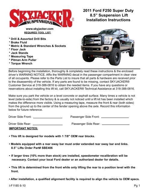
<strong>2011</strong> <strong>Ford</strong> <strong>F250</strong> <strong>Super</strong> <strong>Duty</strong><br />
8.5” <strong>Suspension</strong> <strong>Lift</strong><br />
Installation Instructions<br />
www.skyjacker.com<br />
Required Tool List:<br />
* Drill & Assorted Drill Bits<br />
* Brake Fluid<br />
* Metric & Standard Wrenches & Sockets<br />
* Floor Jack<br />
* Jack Stands<br />
* Measuring Tape<br />
* Pitman Arm Puller<br />
* Torque Wrench<br />
Before beginning the installation, thoroughly & completely read these instructions & the enclosed<br />
driver’s WARNING NOTICE. Affix the WARNING decal in the passenger compartment in clear view<br />
of all occupants. Please refer to the Parts List to insure that all parts & hardware are received prior<br />
to the disassembly of the vehicle. If any parts are found to be missing, contact SKYJACKER®<br />
Customer Service at 318-388-0816 to obtain the needed items. If you have any questions or<br />
reservations about installing this lift kit, call SKYJACKER® Technical Assistance at 318-388-0816.<br />
Make sure you park the vehicle on a level concrete or asphalt surface. Many times a vehicle is not<br />
level (side-to-side) from the factory & is usually not noticed until a lift kit has been installed which<br />
makes the difference more visible. Using a measuring tape, measure the front & rear (both sides)<br />
from the ground up to the center of the fender opening above the axle. Record this information<br />
below for future reference.<br />
Driver Side Front:<br />
Driver Side Rear:<br />
IMPORTANT NOTES:<br />
Passenger Side Front:<br />
Passenger Side Rear:<br />
• This lift is designed for models with 1 7/8" OEM rear blocks.<br />
• Models equipped with a rear sway bar must order extended rear sway bar end links.<br />
8.5” <strong>Lift</strong>s Order Part# SBE406<br />
• If larger tires (10% more than stock) are installed, speedometer recalibration will be<br />
necessary. Contact your local <strong>Ford</strong> dealer or an authorized dealer for details.<br />
• This lift is determined from the front while only lifting the rear to a position level with the<br />
front.<br />
• After installation, a qualified alignment facility is required to align the vehicle to OEM specs.<br />
I-F1185 6-10 Pg 1
Kit Box Breakdown:<br />
Part #: F11852 / F11852S<br />
ITEM# DESCRIPTION QTY<br />
7011-B STAB BRKT,<strong>2011</strong> <strong>F250</strong> 1<br />
TB1180-B TRACK BAR DROP BRACKET, 8.5" 1<br />
RAB545-S RADIUS ARM DROP BRKTS 2<br />
BSB70-DB BUMP STOP BRKT,7"TALL-DRIVR 1<br />
BSB70-PB BUMP STOP BRKT,7"TALL-PASS 1<br />
CBL206-B CARRIER BEARING LOWERING KIT,2” DROP 1<br />
DSS112-1 (F11852S Box) REAR D/S SPCR 6-8" 11 <strong>F250</strong> 1<br />
F118BE-D FRONT BRAKE LINE EXT, DRIVER 1<br />
F118BE-P FRONT BRAKE LINE EXT, PASSENGER 1<br />
HLF1104S HARD LINE,FRONT "S" 2<br />
RB55 5.5" REAR BLOCK 2<br />
(NOT INCLUDED IN F11852S Box)<br />
RBL11S REAR BRAKE LINE W/FITTINGS 2<br />
SBL40-L 4" SWAY BAR LWG BRKT-LEFT 1<br />
SBL40-R 4" SWAY BAR LWG BRKT-RIGHT 1<br />
SP348-B (F11852S Box) REAR SPRING PLATE 11 <strong>F250</strong> 2<br />
VT53229 VACUUM TUBING-5/32"X29" 2<br />
58X325X18SPU U-BOLT (58X325X1212U IN F11852S Box) 4<br />
HB-11250TBS HDWR BAG:TRK BAR,B-STOPS,SWAY BAR 1<br />
HB-DSS112 (F11852S Box) HDWR BAG:D-SHFT SPCR 11<strong>F250</strong> 1<br />
HB-EXH11852S (F11852S Box) HDWR BAG: EXH BRKT 11 <strong>F250</strong> 1<br />
HB-F118BE HDWR BAG:F118BE BRKLINE EXT 1<br />
HB-RABF1146 HDWR BAG:RADIUS DROP BRKTS, 1<br />
I-BL INSTRUCTIONS: BRAKE LINES 1<br />
I-F1185 INSTRUCTION SHEET 1<br />
Hardware Bag Breakdown:<br />
HB-11250TBS<br />
HARDWARE BAG<br />
ITEM# DESCRIPTION QTY<br />
BTIE-K BLACK BOOT TIE 10<br />
D260PSS-S DODGE 02,PIN SUPPORT SLEEVE 3<br />
12MMN 12 MM NUT 1<br />
38X1FTB 3/8 X 1 FINE THREAD BOLT 2<br />
38X112FTB 3/8 X 1 1/2 FINE THRD BOLT 2<br />
38FTN 3/8-24 FINE N/I LOCK NUT 4<br />
38SAEW 3/8 SAE WASHER 4<br />
38X114FW 3/8 X 1 1/4 FENDER WASHER 2<br />
716X112FTB 7/16 X 1 1/2 FINE THRD BLT,GRADE 8 4<br />
716FTN 7/16 FINE THRD NUT 4<br />
716SAEW 7/16 SAE WASHER 8<br />
916X3FTB 9/16 X 3 FINE THREAD BOLT 3<br />
916FTN 9/16-18 NYLON INSERT LOCKNU 3<br />
916SAEW 9/16 SAE WASHERS 6<br />
I-F1185<br />
Pg 2
Hardware Bag Breakdown:<br />
HB-DSS112<br />
HARDWARE BAG<br />
ITEM# DESCRIPTION QTY<br />
12X65SHB 12 X 65MM SOCKET HEAD BOLT 4<br />
LT100 NUTS N' BOLTS 427 1 ML TUBE 1<br />
Hardware Bag Breakdown:<br />
HB-EXH11852S<br />
HARDWARE BAG<br />
ITEM# DESCRIPTION QTY<br />
SSGMOEM SPRING SLEEVE GM OEM FRT 1<br />
8X110MMB 8MM X 110MM BOLT / 10.9 1<br />
516SAEW 5/16 SAE WASHER 1<br />
Hardware Bag Breakdown:<br />
HB-F118BE<br />
HARDWARE BAG<br />
ITEM# DESCRIPTION QTY<br />
38X1TCFB 3/8 X 1 THRD-CUTTER FLG BLT 4<br />
716FTN 7/16-20 FINE N/I LOCK NUT 1<br />
Hardware Bag Breakdown:<br />
HB-RABF1146<br />
HARDWARE BAG<br />
ITEM# DESCRIPTION QTY<br />
ABS55-S ABS RELOCATION BRACKET 2<br />
14X1FTB 1/4 X 1 FINE THREAD BOLT 2<br />
14FTN 1/4" FINE THREAD LOCKNUT 2<br />
14SAEW 1/4 SAE WASHER 4<br />
516X34TCFB 5/16 X 3/4 THD CUT FLG BOLT 2<br />
716X2CTB 7/16 X 2 COARSE BLT,GRADE 8 2<br />
716SAEW 7/16 SAE WASHER 2<br />
58FSFTN 5/8-18 FLANGE STOVER NUT 8<br />
34X2CTB 3/4 X 2 COARSE THREAD BOLT 8<br />
34CTN 3/4" COARSE THREAD LOCKNUT 8<br />
34SAEW 3/4 SAE WASHER 16<br />
I-F1185<br />
Pg 3
Front Installation:<br />
1. With the vehicle on flat level ground, set the emergency brake, &<br />
block the rear tires. Raise the front of the vehicle & support securely<br />
using jack stands.<br />
2. While supporting the front axle with a floor jack, remove the front tires<br />
/ wheels.<br />
3. Disconnect the front sway bar from the frame & install the new<br />
<strong>Skyjacker</strong> sway bar lowering brackets using the 7/16" x 1 1/2" fine<br />
thread bolts, washers, nuts, & OEM hardware. (See Photo # 1)<br />
Photo # 1<br />
4. Remove the retaining clip from the upper brake line bracket & remove<br />
the bracket from the frame. Disconnect the 4WD actuator line from<br />
the upper frame.<br />
5. Disconnect the steering stabilizer from the frame bracket & remove<br />
the bracket from the frame. Disconnect the drag link from the pitman<br />
arm & disconnect the track bar from the track bar bracket using a<br />
1 3/16” socket. (See Photo # 2)<br />
Photo # 2<br />
6. Remove the front shocks & lower the axle so the coil springs can be<br />
removed. (See Photo # 3) Note: Be sure to retain the upper rubber<br />
isolator pads, they will be used with the new <strong>Skyjacker</strong> coil springs.<br />
7. Disconnect the radius arms from the frame brackets using a 15/16”<br />
socket. Note: Remove one side at a time so the axle does not move.<br />
8. Install the new <strong>Skyjacker</strong> radius arm drop brackets, into the OEM<br />
brackets on the frame, using the 3/4" x 2” coarse thread bolts,<br />
washers, & nuts. The outer bolts will install from the outside in & the<br />
inner bolts will install from the inside of the radius arm brackets,<br />
pointing out. (SeePhoto # 4)<br />
9. Attach the new <strong>Skyjacker</strong> radius arms to the new <strong>Skyjacker</strong> radius<br />
arm brackets using the supplied instruction # I-F58484LU.<br />
10. Remove the OEM track bar bracket from the frame & front cross<br />
member using a 21mm & 18mm socket. Loosen & remove the pitman<br />
arm nut from the steering sector shaft using a 1 13/16” socket. Using<br />
a pitman arm puller, remove the pitman arm from the sector. (See<br />
Photo # 5)<br />
Photo # 3<br />
Photo # 4<br />
Photo # 5<br />
I-F1185 Pg 4
11. Before installing the new <strong>Skyjacker</strong> pitman arm, it is EXREMELY<br />
IMPORTANT that the following steps be followed. The thread locking<br />
compound on the threads of the OEM pitman arm nut & the threads<br />
on the steering sector shaft must be thoroughly cleaned & dried<br />
before applying new thread locking compound.<br />
12. Apply a heavy bead of the supplied thread locking compound all<br />
the way around the entire threads of the OEM pitman arm nut.<br />
(See Photo # 6) Once the thread locking compound has been applied,<br />
install the new <strong>Skyjacker</strong> pitman arm & OEM pitman arm nut. Torque<br />
nut to 350 Ft. Lbs!<br />
13. Locate the new <strong>Skyjacker</strong> track bar bracket & bolt the track bar<br />
bracket to the OEM location on the cross member using the 9/16"<br />
x 3” fine thread bolts, washers, & nuts. Note: Be sure to use the<br />
three .938” long anti-crush spacers between the front of the track<br />
bar bracket & the cross member. Note: Do not tighten at this time.<br />
(See Photo # 7)<br />
14. Attach the new <strong>Skyjacker</strong> track bar bracket to the frame using the<br />
OEM hardware.<br />
Photo # 6<br />
Photo # 7<br />
15. Remove the OEM bump stops & bump stop cups from the frame.<br />
The mounting locations on the frame & the bump stop cups must<br />
be drilled to 3/8”. (See Photo # 8) Once drilled, the locator tab on<br />
top of the OEM bump stop cups must be tapped flat so the cups<br />
will sit flush against the new <strong>Skyjacker</strong> bump stop brackets. (See<br />
Photo # 9)<br />
16. Locate the new <strong>Skyjacker</strong> bump stop brackets & attach the wide<br />
end of the new brackets to the OEM positions on the frame. Place a<br />
3/8” small washer on each 3/8" x 1 1/2” fine thread bolt & insert the<br />
bolt through the top hole of each bracket, the frame, & place a large<br />
3/8” fender washer on top of the frame & secure with a 3/8” nut.<br />
Attach the OEM bump stop cups to the bottom of each new bump<br />
stop bracket using a 3/8" x 1” fine thread bolt, washer, & nut. Note:<br />
Do not use a washer under the bolt head. Insert the OEM bump<br />
stop into the OEM bump stop cups. (See Photo # 10)<br />
Photo # 8<br />
Photo # 9<br />
17. Disconnect the ABS lines from the<br />
OEM radius arms using a 13mm<br />
wrench. Attach the OEM ABS<br />
brackets by removing the snap tab<br />
from the rear of the OEM plastic<br />
bracket & drill a 1/4" hole thru the<br />
brackets. Attach the new <strong>Skyjacker</strong><br />
ABS extension brackets to the radius<br />
arms using the 5/16" x 3/4" self<br />
Photo # 10 Photo # 11<br />
tapping bolts & the OEM plastic brackets using the 1/4"<br />
x 1” fine thread bolts, washers, & nuts. (See Photo # 11)<br />
I-F1185<br />
Pg 5
18. Install the new <strong>Skyjacker</strong> coil springs. (See Photo #12) Note: Be<br />
sure to reuse the OEM rubber isolator pads on top of the new coil<br />
springs.<br />
19. Bolt the OEM track bar to the new <strong>Skyjacker</strong> track bar bracket<br />
using the OEM hardware.<br />
20. Using the supplied vaccum line extensions & plastic ties,<br />
reconnect the 4WD actuator line. (See Photo # 13)<br />
21. While holding the OEM rubber brake line in place, remove the OEM<br />
hard brake line from the rubber brake line. Rotate the rubber brake<br />
line 180 degrees & install the new <strong>Skyjacker</strong> S-shape hard brake<br />
line between the OEM hard brake line & the OEM rubber brake<br />
line. (See Photo # 14)<br />
Photo # 12<br />
22. Clamp the new <strong>Skyjacker</strong> brake line extension brackets just below<br />
the opening on each side of the frame & center punch the two<br />
holes that are to be drilled for each bracket. (See Photo # 15)<br />
23. Using a 21/64" drill bit, drill the two holes that were center punched<br />
in Step # 22 & attach the new <strong>Skyjacker</strong> brake line extension<br />
brackets using the 3/8" x 1" self tapping bolts. Secure the OEM<br />
brake lines to the new brackets by inserting the OEM brake line clip<br />
through the groove in the OEM brake line fitting. (See Photo # 16)<br />
Photo # 13<br />
24. Attach the drag link to the new <strong>Skyjacker</strong> pitman arm. With the drag<br />
link installed, check to assure that there is adequate clearance<br />
between the drag link tie rod & the track bar bolt head at full left<br />
turn. If there is any contact, we recommend for the OEM track bar<br />
bolt to be replaced with a 20mm x 90mm (3.5") bolt grade 10.9<br />
(grade 8), & use a 3/4" SAE flat washer between the bolt head &<br />
the new bracket. This will provide some additional clearance, if<br />
needed. (See Photo # 17)<br />
Photo # 14<br />
Photo # 15 Photo # 16 Photo # 17<br />
I-F1185<br />
Pg 6
25. Attach the new <strong>Skyjacker</strong> steering stabilizer bracket to the frame by<br />
aligning the upper mounting hole of the bracket with the upper OEM<br />
stud on the frame & tighten using the OEM hardware. Attach the<br />
OEM stabilizer to the new bracket using the supplied 12mm nut.<br />
(See Photo # 18)<br />
26. Install the new <strong>Skyjacker</strong> front shocks & lower the front of the<br />
vehicle to the ground.<br />
Rear Installation:<br />
Photo # 18<br />
27. Block the front wheels, raise the rear of the vehicle, & support<br />
securely with jack stands.<br />
28. Remove the rear tires / wheels, shocks, & U-bolts. CAUTION: The<br />
rear axle will now be free to move, so support securely with a floor<br />
jack.<br />
29. Disconnect the OEM rear brake lines & attach the new <strong>Skyjacker</strong><br />
brake line extensions to the OEM brake lines. Attach the new<br />
<strong>Skyjacker</strong> brake line extensions to the OEM bracket using the OEM<br />
hardware & supplied plastic ties. (See Photo # 19)<br />
Photo # 19<br />
Rear Leaf Spring Installation:<br />
30. Remove the OEM rear springs & install the new <strong>Skyjacker</strong> rear leaf<br />
springs on top of the OEM blocks with the thick end of the bottom<br />
degree shim towards the rear bumper. Place the new <strong>Skyjacker</strong><br />
spring plates on top of each new leaf spring. (See Photo # 20)<br />
Photo # 20<br />
31. Remove the E-brake cable from the OEM E-brake cable union.<br />
Relocate the E-brake cable above the new rear leaf spring &<br />
conncect the E-brake cable to the OEM E-brake cable union. (See<br />
Photo # 21 & # 22)<br />
32. Remove the OEM rear exhaust hanger bracket & rotate 180<br />
degrees so the exhaust hanger bracket tab is toward the<br />
inside of the frame. Once rotated, attach the OEM rear exhaust<br />
hanger bracket using the 3.5" long anti-crush spacer, 8mm x<br />
110mm bolt, & washer. Once attached, center punch & drill the<br />
bottom mounting hole using a 21/64"<br />
drill bit & tighten using the OEM<br />
hardware. (See Photo # 23)<br />
Photo # 21<br />
Photo # 22<br />
Photo # 23<br />
I-F1185 Pg 7
33. Install the new <strong>Skyjacker</strong> rear driveshaft spacer using the supplied<br />
12mm x 65 mm socket head bolts. Note: Apply the supplied thread<br />
locking compound to the threads of each socket head bolt before<br />
installation. (See Photo # 24) Proceed to Step # 37.<br />
Rear Block & Add A Leaf Installation:<br />
34. Remove the OEM E-brake cable bracket from the OEM leaf spring<br />
center tie bolt.<br />
Photo # 24<br />
35. To perform the installation of add a leafs properly, you must use two<br />
large C-clamps to contain the elastic potential energy in a leaf<br />
spring when the center tie bolts are being removed. Attach &<br />
tighten a C-clamp on each end of the leaf spring to hold the leaf<br />
spring assembly securely together. Using locking pliers to hold the<br />
head of the center tie bolt, loosen & remove the center tie bolt.<br />
With care, slowly loosen & remove the C-clamps. Insert the new<br />
<strong>Skyjacker</strong> center tie bolt thru the OEM bottom overload leaf, new<br />
<strong>Skyjacker</strong> add-a-leaf, & OEM leaf spring pack. Only finger tighten<br />
the nut at this time. DO NOT USE THE CENTER TIE BOLT TO<br />
DRAW THE LEAF SPRING LEAVES TOGETHER. FAILURE OF<br />
ANY COMPONENT CAN CAUSE AN EXPLOSIVE DISASSEMBLY<br />
& POSSIBLE INJURY! Place one C-clamp on each side of the new<br />
center tie bolt & tighten. Once the C-clamps have drawn the leaf<br />
spring securely together, hold the center tie bolt head with locking<br />
pliers & tighten the nut. (See Photo # 25) Remove the C-clamps &<br />
attach the OEM E-brake cable bracket using the supplied 7/16" fine<br />
thread nut. If neccessary, cut off any excess length of the new<br />
center tie bolt.<br />
Photo # 25<br />
Photo # 26<br />
36. Install the new <strong>Skyjacker</strong> rear lift blocks with the taller end toward the rear bumper, between the<br />
axle pad & the OEM blocks Note: The new blocks will be installed below the OEM blocks. (See<br />
Photo # 26)<br />
37. Raise the axle up to the rear leaf springs. Note: Be sure the rear leaf spring center tie bolts &<br />
block pins align in the proper holes & are completely seated. Install & tighten the new <strong>Skyjacker</strong><br />
U-bolts.<br />
38. Install the new <strong>Skyjacker</strong> rear shocks, rear tires / wheels, & lower the vehicle to the ground.<br />
I-F1185 Pg 8
BLEEDING THE BRAKE SYSTEM:<br />
39. Fill the master cylinder with D.O.T. approved brake fluid. Pump the brake pedal & hold down.<br />
While the brake pedal is down, open the bleeder screw to release any air out of the brake<br />
system. Tighten the bleeder screw & re-pump the brake pedal. Continue the pumping / bleeding<br />
process until no air is being expelled. Make sure your master cylinder is full of brake fluid after<br />
each bleeding process. The brake pedal will not "pump up" or will have excessive down-travel if<br />
all the air is not out of the brake system. It is the customer's responsibility to check the brake<br />
lines for any leaks, abrasion, proper clearances, & brake line fittings after the first 100 miles &<br />
after every off-road activity.<br />
40. On models equipped with a carrier bearing on the rear driveshaft,<br />
it will be necessary to install the supplied carrier bearing lowering<br />
bracket to help eliminate any driveline vibration. Install using the<br />
supplied 7/16” bolts & washers. The bracket will mount between the<br />
carrier bearing & the OEM mount on the frame. (See Photo # 2)<br />
Photo # 27<br />
I-F1185 Pg 9
FINAL NOTES:<br />
• After the installation is complete, double check that all nuts & bolts are tight. Refer to the following<br />
chart again for the proper torque specifications. (Do not retighten the nuts & bolts where thread<br />
lock compound was used.)<br />
• With the vehicle placed on the ground, cycle the steering lock to lock & inspect the steering,<br />
suspension, brake lines, front & rear drivelines, fuel lines, & wiring harnesses for proper operation,<br />
tightness, & adequate clearance.<br />
• Have the headlights readjusted to the proper settings.<br />
• Have a qualified alignment center realign the front end to the OEM specifications.<br />
• Retorque all the bolts after the first 100 miles.<br />
Inch System<br />
Bolt Size Grade 5 Grade 8<br />
5/16 15 FT LB 20 FT LB<br />
3/8 30 FT LB 35 FT LB<br />
7/16 45 FT LB 60 FT LB<br />
1/2 65 FT LB 90 FT LB<br />
9/16 95 FT LB 130 FTLB<br />
5/8 135 FT LB 175 FT LB<br />
3/4 185 FT LB 280 FT LB<br />
Torque specificAtions<br />
Metric system<br />
Bolt Size Class 8.8 Class 10.9<br />
6MM 5 FT LB 9 FT LB<br />
8MM 18 FT LB 23 FT LB<br />
10MM 32 FT LB 45 FT LB<br />
12 MM 55 FT LB 75 FT LB<br />
14MM 85 FT LB 120 FT LB<br />
16MM 130 FT LB 165 FT LB<br />
18MM 170 FT LB 240 FT LB<br />
• The above specifications are not to be used when the bolt is being installed with a bushing.<br />
Seat Belts Save Lives, Please Wear Your Seat Belt.<br />
I-F1185 Pg 10
Radius Arm Template - 6” <strong>Lift</strong> Only<br />
Driver’s Side<br />
I-F1185<br />
Pg 11
I-F1185<br />
Pg 12
Radius Arm Template - 6” <strong>Lift</strong> Only<br />
Passenger Side<br />
I-F1185<br />
Pg 13
I-F1185<br />
Pg 14


