lubrication system - JH Bennett & Company, Inc.
lubrication system - JH Bennett & Company, Inc.
lubrication system - JH Bennett & Company, Inc.

You also want an ePaper? Increase the reach of your titles
YUMPU automatically turns print PDFs into web optimized ePapers that Google loves.
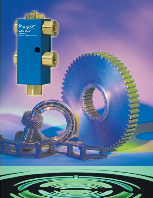
INTRODUCTION<br />
TO PurgeX ®<br />
The patented PurgeX ® pump is one of the<br />
most unique and successful products in<br />
industry today. Since 1988, thousands of<br />
satisfied customers have made PurgeX ®<br />
their choice for reliable and precise<br />
<strong>lubrication</strong>. It is called PurgeX ® because<br />
entrapped air and other impurities are<br />
automatically “purged” from the <strong>system</strong>.<br />
In lab tests, over 360,000,000 cycles<br />
LUBRICATION TRENDS<br />
Why Less Lubrication is Better<br />
Traditionally, <strong>lubrication</strong> users have been under a mis-conception that if a small amount of<br />
liquid is good, then a larger amount of liquid is better. This tendency to over-lubricate has<br />
led to other problems in industry such as material contamination, clean up expenses and<br />
environmental contamination. In some cases, users have removed <strong>lubrication</strong> <strong>system</strong>s<br />
entirely in order to prevent these problems. With the PurgeX ® <strong>system</strong>,<br />
extremely small amounts of lubricant can be applied either directly or by spray.<br />
Advantages of Automatic Lubrication Systems — Many manufacturing companies<br />
continue to use manual <strong>lubrication</strong> methods as well as gravity feed <strong>lubrication</strong> <strong>system</strong>s.<br />
Both of these types of <strong>lubrication</strong> have inherent problems that PurgeX ® can solve.<br />
In manual <strong>system</strong>s, the costs to lubricate can be expensive over the long term. When the<br />
liquid or grease is applied at more lengthy intervals, the <strong>lubrication</strong> benefits are not maximized<br />
(see chart below). In addition, the amount of lubricant that is dispensed varies, leading to<br />
over-<strong>lubrication</strong> or under-<strong>lubrication</strong>.<br />
have been achieved without appreciable<br />
wear. By dispensing very small amounts<br />
of liquid or grease, environmental<br />
contamination is greatly minimized.<br />
Precision output and excellent<br />
repeatability provide higher productivity<br />
rates. In addition, precise metering can<br />
be achieved over a wide range of<br />
VOLUME<br />
MANUAL LUBRICATION<br />
“FLOOD & STARVE”<br />
TIME<br />
EXCESS<br />
OPTIMUM<br />
INSUFFICIENT<br />
VOLUME<br />
AUTOMATIC LUBRICATION<br />
SMALL VOLUMES AT CLOSE<br />
TIME INTERVALS<br />
TIME<br />
EXCESS<br />
OPTIMUM<br />
INSUFFICIENT<br />
adjustability. Some of the more popular<br />
applications for PurgeX ® include:<br />
• Lubricating liquids<br />
• Food additives<br />
In gravity feed <strong>system</strong>s, the liquid is dispensed<br />
through a manually adjusted needle valve. As the<br />
liquid level in the reservoir changes, the drip rate<br />
changes due to the head pressure of the liquid.<br />
This leads to over or under-<strong>lubrication</strong>.<br />
• Greases<br />
• Dyes<br />
• Chemicals<br />
• Solvents<br />
• Inks<br />
OIL-RITE<br />
1-920-682-6173<br />
www.oilrite.com<br />
USA Designed and Manufactured<br />
2
THE PurgeX ® THEORY<br />
How It Works<br />
PurgeX ® is a pump that dispenses a precise amount of lubricant with<br />
each cycle. It is available air operated or electric motor operated, and<br />
can deliver liquid or grease directly through a 1/8” NPT port or<br />
through a spray nozzle.<br />
Adjustment stem for<br />
easy setting of<br />
<strong>lubrication</strong> delivered<br />
per cycle.<br />
AIR INLET<br />
Delivering the Smallest Amounts of<br />
Lubrication<br />
The ability to deliver very small amounts of lubricant with each cycle is what<br />
distinguishes PurgeX ® from all other <strong>lubrication</strong> products. In fact the name<br />
PurgeX ® , comes from its designed ability to purge air from the <strong>lubrication</strong><br />
<strong>system</strong>. This eliminates the need to pre-fill <strong>lubrication</strong> lines during initial<br />
installation. If the liquid reservoir runs low, or air is introduced in some other<br />
manner into the <strong>system</strong>, the self-priming PurgeX ® will fill lines with lubricant<br />
automatically. The net result is the ability to reliably deliver the smallest<br />
amount of lubricant with each cycle.<br />
Anodized<br />
aluminum<br />
body resists<br />
corrosion.<br />
LIQUID INLET<br />
Each PurgeX ® pump has an adjustable precise lubricant delivery per cycle<br />
(see chart 1 below). On air operated models, the liquid output is adjustable<br />
from 0 to .012 cubic inches (.20 cc’s). On electric motor operated models<br />
the output is adjustable from 0 to .009 cubic inches (.15 cc’s). By setting the<br />
cycle rate of the PurgeX ® pump, a wide range of lubricant delivery over time<br />
is achieved. If needed, lubricant delivery can be completely shut off at any<br />
time by adjusting the piston to the fully closed position.<br />
LIQUID IN<br />
As piston moves up the<br />
o-ring shuttles.<br />
Modular<br />
design<br />
allows easy<br />
addition of<br />
more feed<br />
points.<br />
Positive<br />
displacement<br />
design assures<br />
accurate and<br />
repeatable<br />
delivery.<br />
LIQUID OUTLET<br />
Pumping action<br />
produces 20-25” HG<br />
vacuum to pull liquid<br />
into PurgeX ® chamber.<br />
(Depends on viscosity<br />
and length of tubing.)<br />
Can be mounted in<br />
any orientation.<br />
Evacuation valve ensures<br />
positive seal and<br />
consistent delivery with<br />
each cycle<br />
Liquid flows into pump<br />
chamber through piston.<br />
Evacuation valve is<br />
closed by the spring.<br />
Sealing the output line<br />
eliminating “after drip”.<br />
As piston moves down,<br />
the o-ring shuttles.<br />
Pressure increases in pump<br />
chamber forcing evacuation<br />
valve to open, allowing a<br />
measured volume of liquid to<br />
flow out of pump chamber.<br />
Drop Size<br />
(Dia.)<br />
CHART 1<br />
1/4 Stroke<br />
.012 cu.<br />
in.<br />
1/16 95.8 14.20<br />
3/32 28.4 4.20<br />
1/8 12.0 1.70<br />
5/32 6.2 .93<br />
3/16 3.5 .53<br />
Volume Per Turn of<br />
Adjusting Screw<br />
Drops Cu. In.<br />
.0018<br />
Piston continues down and<br />
out of pump chamber<br />
ejecting liquid from the<br />
pump chamber, and<br />
physically contacting the<br />
evacuation valve. This over<br />
travel causes all remaining<br />
air bubbles and small<br />
impurities to flush out of the<br />
pump chamber. These air<br />
bubbles and small impurities<br />
are carried downstream<br />
during each cycle. Also,<br />
eliminates “After-Drip”.<br />
3
THE PurgeX ® THEORY CONTINUED<br />
Typical PurgeX ® System<br />
Requirements<br />
Simplicity of design, installation, and maintenance are the<br />
trademarks of PurgeX ® . Each unit is an independent pump, the<br />
basic requirements include only a lubricant reservoir, 3-way<br />
solenoid valve, timer or sequence signal, tubing and fittings. The<br />
illustration in the figure below, shows a basic <strong>system</strong> with four<br />
lubricant feed points.<br />
Multiple Feed Points<br />
In order to simplify tubing, fittings and mounting requirements in<br />
multiple feed point applications, the patented Threadapter ® <strong>system</strong><br />
is used. Internal connections provide common air and lubricant lines<br />
for all PurgeX ® pumps in the same manifold. It is also easy to<br />
connect additional PurgeX ® pumps to the manifold at any time.<br />
Reservoir<br />
Cycle Timer<br />
Solenoid Valve<br />
Four Feed PurgeX ® Manifold<br />
PurgeX ® MODEL NO. SELECTION CHART<br />
Number<br />
of<br />
Feeds<br />
Lubricant Type<br />
Power Source<br />
Electric Motor*<br />
Delivery Method 1/8” NPT 1/8” NPT Spray** Spray** 1/8” NPT<br />
Reservoir Type Remote Remote Remote Remote Remote<br />
Piston Size 1/4” 1/8” 1/4” 1/8” 1/4”<br />
Catalog Page No. 6-7 8-9 10-11 10-11 12-13<br />
1 B3162-101 B3583-101 B3559-101 B3584-101 B3429-1<br />
2 B3162-102 B3583-102 B3559-102 B3584-102 B3429-2<br />
3 B3162-103 B3583-103 B3559-103 B3584-103 B3429-3<br />
4 B3162-104 B3583-104 B3559-104 B3584-104 B3429-4<br />
5 B3162-105 B3583-105 B3559-105 B3584-105<br />
6 B3162-106 B3583-106 B3559-106 B3584-106<br />
7 B3162-107 B3583-107<br />
8 B3162-108 B3583-108<br />
9 B3162-109 B3583-109<br />
10 B3162-110 B3583-110<br />
11 B3162-111 B3583-111<br />
12 B3162-112 B3583-112<br />
Air Operated<br />
Liquid Delivery<br />
4<br />
*MOTOR VOLTAGE AND SPEED<br />
120V/60hz standard, other voltages and DC motors available on request<br />
1 cycle per minute standard (RPM), other speeds available on request.
Basic Configurations<br />
There are several styles of PurgeX ® for use in a wide range of<br />
applications. Each style is shown below with the corresponding<br />
pages in this catalog where they are found.<br />
Air operated, liquid and grease delivery (pages 6-7).<br />
Air operated, adjustable liquid or grease 1/8” (pages 8-9).<br />
Air operated, spray delivery, for liquid and grease (pages 10-11).<br />
Electric motor operated, liquid delivery (pages 12-13).<br />
Air operated, grease delivery with integral reservoir (pages 14-15).<br />
Electric motor operated, grease delivery with integral reservoir<br />
(pages 14-15).<br />
The Six Pack<br />
Pre-Packaged Systems<br />
The PurgeX ® is also available<br />
in a “ready-to-go” format.<br />
This includes an enclosure<br />
with all internal air, lubricant<br />
and electrical lines connected<br />
and ready to use. Installation<br />
time is minimized and<br />
simplified. Refer to page 16<br />
for complete information.<br />
Grease Delivery<br />
Air Operated<br />
Electric Motor*<br />
1/8” NPT 1/8” NPT 1/8” NPT Spray** Spray** Spray** Spray** 1/8” NPT<br />
Remote Remote Integral Remote Remote Integral Integral Integral<br />
1/4” 1/8” 1/4” 1/4” 1/8” 1/4” 1/8” 1/4”<br />
6-7 8-9 14-15 10-11 10-11 14-15 14-15 14-15<br />
B3162-401 B3583-101 B3325-401 B3559-401 B3584-101 B3560-401 B3586-101 B3477-1<br />
B3162-402 B3583-102 B3325-402 B3559-402 B3584-102 B3560-402 B3560-102 B3477-2<br />
B3162-403 B3583-103 B3325-403 B3559-403 B3584-103 B3560-403 B3586-103 B3477-3<br />
B3162-404 B3583-104 B3325-404 B3559-404 B3584-104 B3560-404 B3586-104 B3477-4<br />
B3162-405 B3583-105 B3325-405 B3559-405 B3584-105 B3560-405 B3586-105<br />
B3162-406 B3583-106 B3325-406 B3559-406 B3584-106 B3560-406 B3586-106<br />
B3162-407 B3583-107 B3325-407<br />
B3162-408 B3583-108 B3325-408<br />
B3162-409 B3583-109<br />
B3162-410 B3583-110<br />
B3162-411 B3583-111<br />
B3162-412 B3583-112<br />
** NOZZLE LENGTH ON SPRAY MODELS<br />
8 inch length standard, other lengths available on request<br />
SEALS<br />
Buna-N standard, other seals available on request 5
AIR OPERATED, LIQUID OR GREASE DELIVERY<br />
The B3162-100 & 300 series of PurgeX ® is air operated and designed for use with a wide<br />
variety of liquids and lubricating oils. The B3162-400 series of PurgeX ® is air operated<br />
and designed for grease delivery. A remote, pressurized grease reservoir is used to<br />
deliver grease to the PurgeX ® pump. An internal ball check in the outlet port permits<br />
pressurized delivery of the grease to the PurgeX ® pump. PurgeX ® pumps are quality<br />
engineered, manufactured, provide simplicity of operation, and are reliable over long<br />
periods of time (over 360,000,000 cycles have been achieved). Precise volumetric<br />
delivery is achieved with a positive displacement design and adjustment capability.<br />
• Air pressure from 3-way solenoid valve begins <strong>lubrication</strong> cycle.<br />
• When the air pressure is removed, the internal piston and evacuation valve retract,<br />
drawing liquid into the pumping chamber with a vacuum of 20-25” HG, preventing<br />
any after-drip of liquid.<br />
• A 9:1 ratio of the air side to the lube side of the piston provides reliable delivery<br />
in all typical applications.<br />
• For applications with multiple feed points, the PurgeX ® is supplied in a manifold with<br />
common air and liquid or grease inlet ports, using the Threadapter ® connector. Each<br />
PurgeX ® in the manifold operates as an individual pump with a separate adjustment<br />
for lubricant delivery per cycle.<br />
• PurgeX ® pump delivers small amounts of liquid/grease per cycle and can be rapid<br />
cycled for greater volumes or is excellent for high speed applications.<br />
B3162<br />
TYPICAL INSTALLATION<br />
Installation for B3162 (Liquid)<br />
Reservoir<br />
Cycle Timer<br />
Six Feed<br />
PurgeX ® Manifold<br />
Solenoid Valve<br />
6<br />
In the application shown above, the PurgeX ® <strong>system</strong> is<br />
used to lubricate chains in a packaging operation. Small<br />
amounts of liquid are precisely delivered, eliminating<br />
package contamination in this process. The basic<br />
requirements include only a lubricant reservoir, 3-way<br />
solenoid valve, cycle timer or sequence signal, tubing<br />
and fittings.<br />
Air pressure<br />
Body<br />
Seals<br />
SPECIFICATIONS<br />
40-120 psi<br />
Anodized aluminum alloy<br />
(other materials available)<br />
Buna-N & Viton ® (other materials available)<br />
Liquid/Grease<br />
delivery per cycle<br />
0 to .012 cu. in., adjustable<br />
Temperature range -15º F to 180º F<br />
Piston ratio 9:1<br />
Piston diameter & stroke .250 dia. by .250 stroke (inches)<br />
Grease type Grade 00, 0, 1, 2
HOW TO ORDER<br />
1. Determine number<br />
of <strong>lubrication</strong><br />
points and select<br />
corresponding<br />
PurgeX ® model<br />
with the correct<br />
number of feeds.<br />
2. Select liquid or<br />
grease reservoir<br />
with appropriate<br />
capacity.<br />
3. Select a 3-way<br />
solenoid operated<br />
air valve to turn<br />
<strong>lubrication</strong> cycle<br />
on and off.<br />
4. Select a timer<br />
or use machine<br />
controls to signal<br />
solenoid valve.<br />
5. Select tubing and<br />
fittings.<br />
Installation for B3162 (Grease)<br />
Cycle Timer<br />
Solenoid Valve<br />
Single Feed PurgeX ®<br />
Grease Reservoir<br />
See pages 19 and 20<br />
for accessory model<br />
numbers<br />
SELECTION CHART<br />
In the application above, a PurgeX ® is supplying<br />
precise amounts of grease to a bearing, eliminating the<br />
need for manual <strong>lubrication</strong> and extending bearing life.<br />
Catalog Numbers<br />
Buna-N seals Viton ® seals Grease<br />
No. of<br />
Feeds<br />
A<br />
Ref.<br />
B3162-101 B3162-301 B3162-401 1 2<br />
B3162-102 B3162-302 B3162-402 2 3-1/4<br />
B3162-103 B3162-303 B3162-403 3 4-1/2<br />
B3162-104 B3162-304 B3162-404 4 5-3/4<br />
B3162-105 B3162-305 B3162-405 5 7<br />
B3162-106 B3162-306 B3162-406 6 8-1/4<br />
B3162-107 B3162-307 B3162-407 7 9-1/2<br />
B3162-108 B3162-308 B3162-408 8 10-3/4<br />
B3162-109 B3162-309 B3162-409 9 12<br />
B3162-110 B3162-310 B3162-410 10 13-1/4<br />
B3162-111 B3162-311 B3162-411 11 14-1/2<br />
B3162-112 B3162-312 B3162-412 12 15-3/4<br />
1/8” NPT Liquid or Grease<br />
Outlet(s)<br />
A Ref.<br />
Liquid or Grease Output Adjustment Stem<br />
1.25” Hole<br />
Centers<br />
9/32” DIA.<br />
Mtg. Holes<br />
1/8”<br />
NPT Air<br />
Inlet<br />
1/8” NPT<br />
Liquid or<br />
Grease<br />
Inlet<br />
Viton ® is a registered trademark of DuPont<br />
4.06” (for<br />
Grease Unit)<br />
4.00” (for<br />
Liquid Unit)<br />
7
ULTRA-MICRO OUTPUT PurgeX ® ADJUSTABLE<br />
AIR OPERATED, with 1/8” PISTON<br />
The B3583 series of PurgeX ® is air operated and designed for liquid or grease delivery.<br />
With ultra-fine adjustability, the single piece 1/8” piston allows precise metering of very<br />
small volumes of liquid or grease. The patented 1/8” version will help preserve liquid<br />
supplies, dispense high cost synthetic lubricants more efficiently and aid in pollution<br />
prevention. Quality engineering and manufacturing provide simplicity of operation and<br />
reliability over long periods of time. Precise volumetric delivery is achieved with a positive<br />
displacement design and adjustment capability.<br />
• Air pressure from 3-way solenoid valve begins <strong>lubrication</strong> cycle.<br />
• High output pressures can be achieved due to a 25:1 ratio from air inlet to liquid<br />
outlet.<br />
• Operation is simple. Liquid is pulled from a reservoir to the PurgeX ® pump due to<br />
vacuum generated by pump. Reservoir location is not critical since each PurgeX ®<br />
pump is a self-contained injector that can operate in any orientation.<br />
• For applications with multiple feed points, the PurgeX ® is supplied in a manifold with<br />
common air and liquid/grease inlet ports, using the Threadapter ® connector. Each<br />
PurgeX ® in the manifold operates as an individual pump with a separate adjustment<br />
for lubricant delivery per cycle.<br />
• PurgeX ® with ultra-micro output can be used with a wide range of liquids or<br />
chemicals that demand critical flow control.<br />
B3583<br />
TYPICAL INSTALLATION<br />
Installation for B3583 (Liquid)<br />
Solenoid Valve<br />
Reservoir<br />
PurgeX ®<br />
Adjustable 1/8”<br />
Air Operated<br />
Unit<br />
In the application shown, PurgeX ® with ultra-micro<br />
adjustment delivers precise amount of liquid to a chain<br />
<strong>lubrication</strong> <strong>system</strong>, eliminating the need for manual<br />
<strong>lubrication</strong> and extending chain life. The basic<br />
requirements include only a lubricant reservoir, 3-way<br />
solenoid valve, cycle timer or sequence signal, tubing and<br />
fittings.<br />
SPECIFICATIONS<br />
Air pressure<br />
40-120 psi<br />
Body<br />
Anodized aluminum alloy<br />
(other materials available)<br />
Seals<br />
Buna-N & Viton ® (other materials available)<br />
Liquid/Grease delivery<br />
per cycle<br />
0 to .0012 cu. in., adjustable<br />
Temperature range -15º F to 180º F<br />
Piston ratio 25:1<br />
8<br />
Piston diameter & stroke .125 dia. by .100 stroke (inches)<br />
Grease type Grade 00, 0, 1, 2
HOW TO ORDER<br />
1. Determine number<br />
of <strong>lubrication</strong><br />
points and select<br />
corresponding<br />
PurgeX ® model with<br />
the correct number<br />
of feeds.<br />
Installation for B3583 (Grease)<br />
In the application shown, PurgeX ® with<br />
ultra-micro adjustment delivers precise amount<br />
of grease to a <strong>lubrication</strong> <strong>system</strong>, eliminating<br />
the need for manual <strong>lubrication</strong>.<br />
Reservoir<br />
2. Select a reservoir<br />
with appropriate<br />
capacity.<br />
3. Select a 3-way<br />
solenoid operated<br />
air valve to turn<br />
<strong>lubrication</strong> cycle<br />
on and off.<br />
4. Select a timer<br />
or use machine<br />
controls to signal<br />
solenoid valve.<br />
Four Feed<br />
Adjustable 1/8”<br />
Air Operated<br />
Unit<br />
Liquid<br />
Cycle<br />
Timer<br />
Solenoid Valve<br />
5. Select tubing and<br />
fittings.<br />
Air Inlet<br />
See pages 19 and<br />
20 for accessory<br />
model numbers<br />
SELECTION CHART<br />
Catalog Numbers<br />
Buna-N Seals Viton ® Seals<br />
No. of<br />
Feeds<br />
A<br />
Ref.<br />
B3583-101 B3583-301 1 2<br />
A Ref.<br />
B3583-102 B3583-302 2 3-1/4<br />
B3583-103 B3583-303 3 4-1/2<br />
1/8”<br />
NPT Air<br />
Inlet<br />
B3583-104 B3583-304 4 5-3/4<br />
B3583-105 B3583-305 5 7<br />
9/32” DIA.<br />
Mtg. Holes<br />
4.13”<br />
Ref.<br />
B3583-106 B3583-306 6 8-1/4<br />
B3583-107 B3583-307 7 9-1/2<br />
1/8” NPT<br />
Liquid<br />
Inlet<br />
B3583-108 B3583-308 8 10-3/4<br />
B3583-109 B3583-309 9 12<br />
B3583-110 B3583-310 10 13-1/4<br />
B3583-111 B3583-311 11 14-1/2<br />
B3583-112 B3583-312 12 15-3/4<br />
Viton ® is a registered trademark of DuPont<br />
1/8” NPT Liquid Outlet (s)<br />
9
1/8” AND 1/4” AIR OPERATED, SPRAY<br />
DELIVERY, FOR LIQUID OR GREASE<br />
PurgeX ® is an excellent way to spray both liquid or grease at the desired point. Separate<br />
controls for both the air and lubricant delivery are provided. The lubricant and the air<br />
mix at the nozzle tip to maximize delivery efficiency. Quality engineering and<br />
manufacturing provide simplicity of operation and reliability over long periods of time.<br />
Precise volumetric delivery is achieved with a positive displacement design and<br />
adjustment capability.<br />
• Air pressure from 3-way solenoid valve begins <strong>lubrication</strong> cycle.<br />
• When the air pressure is removed, the internal piston and evacuation valve retract,<br />
allowing liquid or grease to enter the pumping chamber.<br />
• For applications with multiple feed points, the PurgeX ® is supplied in a manifold with<br />
common air and liquid/grease inlet ports, using the Threadapter ® connector. Each<br />
PurgeX ® in the manifold operates as an individual pump with a separate adjustment<br />
for lubricant delivery per cycle.<br />
• In liquid delivery applications, the air operated design allows use in high cycle<br />
speed applications, delivering small amounts of liquid per cycle.<br />
• Integral 8 inch coaxial spray nozzle is flexible yet rigid enough to allow for precise<br />
positioning of the nozzle to target. Other lengths are available upon request.<br />
B3584<br />
B3559<br />
TYPICAL INSTALLATION<br />
B3559 Installation of PurgeX ®<br />
Spray Pump<br />
Solenoid Valve<br />
Air In<br />
The PurgeX ® spray <strong>system</strong> is an excellent method<br />
to deliver grease in gear <strong>lubrication</strong> applications.<br />
Contact with the gears is not required.<br />
Precise, timed delivery of grease is achieved.<br />
Air<br />
Grease Reservoir<br />
Single Feed PurgeX ®<br />
w/ Spray Nozzle<br />
Outlet to Gears<br />
10<br />
Air Pressure<br />
Body<br />
Seals<br />
Liquid/Grease delivery<br />
per cycle<br />
Temperature range<br />
Piston ratio<br />
Piston diameter and stroke<br />
SPECIFICATIONS<br />
40-120 psi<br />
Anodized aluminum alloy (other materials available)<br />
Buna-N & Viton ® (other materials available)<br />
1/4” piston 0 to .012 cu. in., adjustable<br />
1/8” piston 0 to .0012 cu. in., adjustable<br />
-15º F to 180º F<br />
1/4” piston 9:1<br />
1/8” piston 25:1<br />
1/4” piston .250 dia. by .250 stroke<br />
1/8” piston .125 dia. by .100 stroke<br />
Grease type Grade 00, 0, 1, 2<br />
Nozzle length<br />
8 inches std. (other sizes available)
HOW TO ORDER<br />
1. Determine number<br />
of <strong>lubrication</strong><br />
points and select<br />
corresponding<br />
PurgeX ® model<br />
with the correct<br />
number of feeds.<br />
2. Select liquid or<br />
grease reservoir<br />
with appropriate<br />
capacity.<br />
3. Select a 3-way<br />
solenoid operated<br />
air valve to turn<br />
<strong>lubrication</strong> cycle<br />
on and off.<br />
4. Select a timer<br />
or use machine<br />
controls to signal<br />
solenoid valve.<br />
5. Select tubing and<br />
fittings.<br />
See pages 19 and<br />
20 for accessory<br />
model numbers<br />
B3584 Installation of PurgeX ® Spray Injector Pump<br />
Cycle Timer<br />
Air<br />
Liquid<br />
1/8” Single Feed PurgeX ®<br />
w/ Spray Nozzle<br />
Flexible Nozzle<br />
Liquid & Air<br />
Spray Pattern<br />
Solenoid Valve<br />
Reservoir<br />
Simplicity of design, installation, and maintenance<br />
are the trademarks of PurgeX ® . The basic<br />
requirements include only a lubricant reservoir,<br />
3-way solenoid valve, cycle timer or sequence<br />
signal, tubing and fittings. The illustration shows a<br />
basic <strong>system</strong> with a single lubricant feed point.<br />
SELECTION CHART<br />
Liquid/Grease Spray Liquid Spray<br />
Grease<br />
1/8”<br />
1/4” No. of A<br />
Spray 1/4”<br />
Feeds Ref.<br />
Buna-N Viton ® Buna-N Viton<br />
Buna-N<br />
®<br />
B3584-101 B3584-301 B3559-101 B3559-301 B3559-401 1 1-31/32<br />
B3584-102 B3584-302 B3559-102 B3559-302 B3559-402 2 3-7/32<br />
4.16”<br />
Ref.<br />
B3584<br />
A Ref.<br />
Liquid/Grease<br />
Output Adj.<br />
Stem<br />
1/8” N.P.T.<br />
Air Inlet<br />
9/32” Dia.<br />
Mtg. Holes<br />
1/8” N.P.T.<br />
Liquid/Grease<br />
Inlet<br />
4”<br />
Ref.<br />
B3559<br />
A Ref.<br />
Liquid/Grease<br />
Output Adj.<br />
Stem<br />
1/8” N.P.T.<br />
Air Inlet<br />
9/32” Dia.<br />
Mtg. Holes<br />
1/8” N.P.T.<br />
Liquid/Grease<br />
Inlet<br />
B3584-103 B3584-303 B3559-103 B3559-303 B3559-403 3 4-15/32<br />
B3584-104 B3584-304 B3559-104 B3559-304 B3559-404 4 5-23/32<br />
Air Spray<br />
Adjustment Stem<br />
Air Spray<br />
Adjustment Stem<br />
B3584-105 B3584-305 B3559-105 B3559-305 B3559-405 5 6-31/32<br />
B3584-106 B3584-306 B3559-106 B3559-306 B3559-406 6 8-7/32<br />
Viton ® is a registered trademark of DuPont<br />
Spray Outlet<br />
Spray Outlet<br />
11
ELECTRIC MOTOR OPERATED, LIQUID DELIVERY<br />
Ultimate in liquid adjustability and output accuracy, the Electric<br />
motor operated versions of PurgeX ® are used in applications<br />
where compressed air is not available or where direct interface<br />
to machine controls is desired. Lubrication cycles are easily<br />
synchronized to machine operation. Quality engineering and<br />
manufacturing provide simplicity of operation and reliability<br />
over long periods of time. Precise volumetric delivery is<br />
achieved with a positive displacement design and adjustment<br />
capability.<br />
• With each complete revolution of the motor (RPM), one<br />
<strong>lubrication</strong> cycle occurs, dispensing a maximum of .009<br />
cubic inches (.15 cc’s), per feed point.<br />
• Standard motor speed is one revolution per minute. Other<br />
motor speeds are available on request.<br />
• Standard voltage is 120V/60Hz and different voltages can<br />
also be supplied.<br />
• Single piece piston pump provides the ultimate in liquid<br />
adjustability and output accuracy. The pump is<br />
electrically driven and requires no other external energy<br />
source.<br />
B3429<br />
TYPICAL INSTALLATION<br />
Installation for B3429 (Liquid)<br />
2 Feed PurgeX ®<br />
Manifold<br />
In this <strong>lubrication</strong> application, using only<br />
a reservoir, a PurgeX ® pump and nylon<br />
brushes, liquid is delivered to a pinion<br />
gear. The brushes disperse the liquid over<br />
the entire surface area of the gears.<br />
Reservoir<br />
12<br />
SPECIFICATIONS<br />
Body<br />
Anodized aluminum alloy (other materials available)<br />
Seals<br />
Buna-N & Viton ® (other materials available)<br />
Liquid delivery per cycle 0 to .009 cu. in., adjustable<br />
Temperature range -15º F to 120º F<br />
Motor voltage<br />
Current draw<br />
Motor speed<br />
120V/60Hz (other voltages available)<br />
.025 amps at 120 volts<br />
1 RPM (other speeds available)
HOW TO ORDER<br />
Installation for B3429 (Liquid)<br />
1. Determine number of<br />
<strong>lubrication</strong> points and<br />
select corresponding<br />
PurgeX ® model with the<br />
correct number of feeds.<br />
2. Select liquid reservoir<br />
with appropriate capacity.<br />
3. Use machine controls or<br />
other remote signal to<br />
provide power to electric<br />
motor. (Cycle rate is continuous<br />
as long as power<br />
is supplied to the motor.)<br />
Sprocket Location<br />
Minimizing Nozzle<br />
Overspray<br />
Continuos Air<br />
Supply 5 PSI or Less<br />
Extruded Plastic<br />
Component Prevents<br />
Overhead Application<br />
VIEW A-A<br />
Remote Mount<br />
Elbow Spray Nozzle<br />
Reservoir<br />
Cycle<br />
Timer<br />
4. Standard, 1 RPM motor.<br />
Other speeds available<br />
upon request.<br />
5. Select tubing and fittings.<br />
Liquid<br />
Motor Operated PurgeX ®<br />
Injector Pump<br />
Air<br />
See pages 19 and 20 for<br />
accessory model numbers<br />
In this <strong>lubrication</strong> application, using only<br />
a reservoir, a PurgeX ® motor pump and a<br />
cycle timer, the liquid is being delivered to a<br />
horizontal chain drive.<br />
SELECTION CHART<br />
Motor Driven<br />
Catalog Number<br />
(AC)<br />
Catalog Number<br />
(DC)<br />
W/Bracket W/Elec. Box W/Bracket W/Elec. Box<br />
No. of<br />
Feeds<br />
A B C<br />
B3429-1 B3429-11 B3473-1 B3473-11 1 1-5/8 25/32 1-1/16<br />
B3429-2 B3429-12 B3473-2 B3473-12 2 2-15/32 1-9/16 1-1/2<br />
B3429-3 B3429-13 B3473-3 B3473-13 3 3-5/16 2-3/8 1-15/16<br />
B3429-4 B3429-14 B3473-4 B3473-14 4 4-5/32 3-3/16 2-5/16<br />
Ass’y<br />
w/Bracket<br />
1-5/8”<br />
21/32”<br />
C<br />
B<br />
A<br />
1/8” NPT<br />
Liquid In<br />
Ass’y<br />
w/Elec.<br />
Box<br />
2-7/32” 1-1/16” 27/32” 27/32” 27/32”<br />
1-3/4”<br />
13/64”<br />
Dia.Mtg.<br />
Holes<br />
1-13/16”<br />
1/8” NPT<br />
Liquid Outlet<br />
External Adjustment Motor<br />
Catalog Number<br />
(AC External Adjustment)<br />
W/Bracket W/Elec. Box W/Bracket W/Elec. Box<br />
Viton ® is a registered trademark of DuPont<br />
Catalog Number<br />
(DC External Adjustment)<br />
No. of<br />
Feeds<br />
A B C<br />
B3474-1 B3474-11 B3475-1 B3475-11 1 2-19/32 1-7/8 1-1/2<br />
B3474-2 B3474-12 B3475-2 B3475-12 2 2-19/32 1-7/8 1-1/2<br />
B3474-3 B3474-13 B3475-3 B3475-13 3 3-15/32 2-3/4 2-11/32<br />
B3474-4 B3474-14 B3475-4 B3475-14 4 4-9/32 3-9/16 2-11/32<br />
9/32”<br />
Dia.Mtg.<br />
Holes<br />
Ass’y<br />
w/Bracket<br />
1-5/8”<br />
Ass’y w/Elec. Box<br />
2-7/32”<br />
9/16”<br />
1-1/16”<br />
C<br />
B<br />
A<br />
27/32” 27/32” 27/32”<br />
1/8” NPT<br />
Liquid In<br />
31/32”<br />
1-3/4”<br />
1-13/16”<br />
1/8” NPT<br />
Liquid Outlet<br />
13
AIR AND ELECTRIC MOTOR OPERATED WITH<br />
INTEGRAL GREASE RESERVOIR<br />
Entirely engineered and precision<br />
manufactured in the USA, these grease<br />
pump <strong>system</strong>s employ the patented<br />
PurgeX ® technology and will dispense an<br />
accurate volume each cycle. The metering<br />
<strong>system</strong>s can be used with a wide range of<br />
greases that demand critical flow control.<br />
Grease is supplied from a rugged<br />
fiberglass reservoir to the pump. An air<br />
signal pulses the single piece piston<br />
causing a pre-determined amount of grease<br />
to be ejected. Location of the meter is not<br />
critical as the meter can be mounted in any<br />
orientation. For safety purposes, a relief<br />
valve is incorporated into the injector<br />
block. Each PurgeX ® operates as an<br />
individual pump and is available in single<br />
feed or multiple feed manifolds.<br />
B3560<br />
B3477<br />
B3325<br />
• For applications with multiple feed points,<br />
the Threadapter ® is a fastener for securing<br />
the two pumps together, which allows fluid<br />
communication in the manifold. This<br />
exclusive and unique feature allows the<br />
option of changing the units in the field by<br />
merely adding additional pumps.<br />
Air Pressure<br />
Body<br />
Seals<br />
Grease delivery per cycle<br />
(air operated models)<br />
Grease delivery per cycle<br />
(electric motor operated models)<br />
Temperature range<br />
Piston ratio<br />
(air operated models)<br />
Motor voltage<br />
Current draw<br />
Motor speed<br />
Nozzle length<br />
SPECIFICATIONS<br />
40-120 psi<br />
Anodized aluminum alloy (other materials available)<br />
Buna-N & Viton ® (other materials available)<br />
1/4” piston 0 to .012 cu. in., adjustable<br />
1/8” piston 0 to .0012 cu. in., adjustable<br />
1/4” piston 0 to .009 cu. in., adjustable<br />
-15º F to 180º F (air operated models)<br />
-15º F to 120º F (elec. mtr. operated)<br />
1/4” piston 9:1<br />
1/8” piston 25:1<br />
120V/60Hz (other voltages available)<br />
.025 amps at 120 volts<br />
1 RPM (other RPM’s available)<br />
8 inches (other sizes available)<br />
Grease type Grade 00, 0, 1, 2<br />
SELECTION CHART<br />
AIR OPERATED, 1/4” PISTON<br />
Catalog No.<br />
No. of<br />
Feeds<br />
A B<br />
B3325-401 1 3-1/4 2-3/8<br />
B3325-402 2 4-1/2 2-3/8<br />
B3325-403 3 5-3/4 3-5/8<br />
B3325-404 4 7 3-5/8<br />
B3325-405 5 8-1/4 4-7/8<br />
B3325-406 6 9-1/2 4-7/8<br />
B3325-407 7 10-3/4 6-1/8<br />
B3325-408 8 12 6-1/8<br />
8.06”<br />
Vent<br />
A<br />
B<br />
1.25”<br />
Grease<br />
Output<br />
Adjustment<br />
Stem<br />
1/8” NPT<br />
Air Inlet<br />
9/32” Dia.<br />
MTG<br />
Holes<br />
Grease<br />
Fill<br />
Fitting<br />
14<br />
1/8” NPT Grease Outlet(s)<br />
Relief Valve
1. Determine number of <strong>lubrication</strong> points<br />
and select corresponding PurgeX ®<br />
model with the correct number of feeds.<br />
2. If air operated, select a 3-way solenoid<br />
operated air valve to turn <strong>lubrication</strong><br />
cycle on and off. Select a timer or use<br />
machine controls to signal solenoid<br />
valve.<br />
3. If electric motor operated, use<br />
machine controls or other remote<br />
signal to provide power to electric<br />
motor. (Cycle rate is continuous as long<br />
as power is supplied to the motor.)<br />
Standard, 1 RPM motor. Other speeds<br />
available.<br />
4. Select tubing and fittings.<br />
See pages 19 and 20 for accessory<br />
model numbers<br />
SELECTION CHART<br />
HOW TO ORDER<br />
Installation for B3560 (Grease Spray)<br />
Integral Grease<br />
Reservoir<br />
Air<br />
Single Feed PurgeX ®<br />
w/ Spray Nozzle<br />
Flexible Nozzle (Std. 8” Length)<br />
Grease & Air<br />
Spray Pattern<br />
SELECTION CHART<br />
Cycle Timer<br />
Solenoid Valve<br />
Each unit is an independent pump.<br />
The basic requirements include,<br />
3-way solenoid valve, cycle timer or<br />
sequence signal, tubing, and<br />
fittings.<br />
AIR OPERATED SPRAY, 1/4” OR 1/8” PISTON<br />
Catalog No.<br />
1/4” Spray<br />
Grease<br />
Vent<br />
Catalog No.<br />
1/8” Spray Grease<br />
Buna-N seals<br />
(not shown)<br />
A<br />
Catalog No.<br />
1/8” Spray Grease<br />
Viton ® seals<br />
(not shown)<br />
No. of<br />
Feeds<br />
B3560-401 B3586-101 B3586-301 1 3-7/32<br />
B3560-402 B3586-102 B3586-302 2 4-15/32<br />
B3560-403 B3586-103 B3586-303 3 5-23/32<br />
B3560-404 B3586-104 B3586-304 4 6-31/32<br />
B3560-405 B3586-105 B3586-305 5 8-7/32<br />
B3560-406 B3586-106 B3586-306 6 9-15/32<br />
A<br />
ELECTRIC MOTOR OPERATED<br />
Catalog No.<br />
No. of<br />
Feeds<br />
A B C<br />
B3477-1 1 1-5/8 25/32 1-1/16<br />
B3477-2 2 2-15/32 1-9/16 1-1/2<br />
B3477-3 3 3-5/16 2-3/8 1-15/16<br />
B3477-4 4 4-5/32 3-3/16 2-5/16<br />
Consult factory:<br />
1. Other AC and DC motor voltages and RPM’S available.<br />
C<br />
A<br />
Grease<br />
Output<br />
Adjustment<br />
Stem<br />
8.00”<br />
Ref.<br />
1.25”<br />
1/8” NPT<br />
Air Inlet<br />
9/32” Dia.<br />
MTG<br />
Holes<br />
Grease<br />
Fitting<br />
Relief<br />
Valve<br />
Grease Fill<br />
Fitting<br />
13/64” Dia.<br />
MTG Holes<br />
8 7/16”<br />
3 35/64”<br />
Air<br />
Adjustment<br />
Stem<br />
Relief<br />
Valve<br />
Spray<br />
Outlet (s)<br />
1-5/8 w/bracket<br />
2-7/32 w/ elec.<br />
box 21/32”<br />
1 1/16”<br />
27/32”<br />
B<br />
1/8” NPT Grease Outlet (s)<br />
15
THE SIX PACK<br />
“READY TO GO” LUBRICATION SYSTEM<br />
The Six Pack <strong>system</strong> from Oil-Rite ® provides simplicity and convenience in one easy to<br />
use package. Each <strong>system</strong> is equipped with a bank of air operated PurgeX ® pumps. A<br />
solid state timer controls the “on” and “off” times of the delivery cycle through a 3-way<br />
solenoid valve. All components are wired and plumbed to a back plate that is enclosed<br />
in a hinged door NEMA 12 enclosure, protecting components from the environment. A<br />
rugged 1/2 gallon crystal clear polycarbonate reservoir with a hinged lid mounted on<br />
top, feeds the <strong>system</strong> and allows for visual confirmation of the fluid level. This <strong>system</strong><br />
proves a valuable solution for many applications. Each pump operates independently,<br />
allowing for individual adjustment of flow to each lube point. This precise delivery<br />
allows for efficient use of expensive fluids as well as virtually eliminating any excess<br />
fluid entering the environment.<br />
• No Priming Necessary-Positive Inlet Suction<br />
• Purges entrained air-will not vapor lock<br />
• Suck-Back feature (no after drip) from outlet<br />
• Vacuum of 20”-25” Hg generated on fluid inlet<br />
1/2 Gallon<br />
Polycarbonate<br />
Reservoir<br />
SELECTION CHART<br />
5/16” Dia. Mtg.<br />
Holes (4 Places)<br />
NEMA 12<br />
(Gasketed)<br />
Enclosure<br />
Catalog No. Description<br />
B3471-106 6 point <strong>lubrication</strong> <strong>system</strong><br />
B3471-112 12 point <strong>lubrication</strong> <strong>system</strong><br />
10 3/4”<br />
21-1/2”<br />
Ref.<br />
B3471<br />
B3471-118 18 point <strong>lubrication</strong> <strong>system</strong><br />
13” W/Door Open<br />
6”<br />
8”<br />
TYPICAL INSTALLATION<br />
In this application, the Six Pack is used<br />
to provide 6 points of <strong>lubrication</strong> for<br />
chains, gears, and bearings. Complete<br />
turn-key <strong>system</strong>s.<br />
Reservoir<br />
PurgeX 6 point<br />
manifold<br />
NEMA 12<br />
enclosure<br />
SPECIFICATIONS<br />
Air pressure<br />
40-120 psi<br />
Seals<br />
Buna-N & Viton ® (other seals available)<br />
Liquid delivery per cycle 0 to .012 cu. in., adjustable<br />
Temperature range -15º F 180º F<br />
Piston ratio 9:1<br />
Piston diameter and stroke .250 dia by .250 stroke (inches)<br />
Reservoir capacity 1/2 gallon (other capacities available)<br />
Voltage requirement 120V/60Hz (other voltages available)<br />
Enclosure NEMA 12<br />
16
QUICK PACK ®<br />
CENTRALIZED LUBRICATION SYSTEMS<br />
The Quick Packs ® are economically priced and easy to install. Supplied with an easy to fill<br />
reservoir, fully adjustable cycle timer and rugged mounting plate, these units are<br />
suitable wherever accuracy, simplicity and economy are required. The Quick Pack ® units<br />
are available in both air and motor operated <strong>system</strong>s for liquid or grease in banks of 2 to<br />
36 connected pumps. Controlled by a repeat cycle timer, PurgeX ® pumps immediately<br />
deliver the liquid or grease from a central reservoir to the point of application.<br />
Complete turn-key <strong>system</strong>s.<br />
10 7/8” Ref.<br />
Lubricant<br />
Type<br />
Power<br />
Source<br />
Reservoir<br />
Cap.<br />
Number of Feeds<br />
SELECTION CHARTS:<br />
Liquid Delivery<br />
Air<br />
Operated<br />
Quart or<br />
Pint<br />
Motor<br />
Operated<br />
Quart or<br />
Pint<br />
Grease Delivery<br />
Air<br />
Operated<br />
1.5 oz.<br />
Integral<br />
Motor<br />
Operated<br />
1.5 oz.<br />
Integral<br />
10 3/4”<br />
Ref.<br />
B3544 Air Operated - Liquid<br />
Air pressure (air operated)<br />
Body<br />
SPECIFICATIONS:<br />
40-120 psi<br />
1/8” Female NPT<br />
Outlets<br />
Aluminum Alloy (other materials available)<br />
Seals<br />
Buna-N & Viton ® (other materials available)<br />
Temperature range<br />
-15º F to 180º F (air operated)<br />
-15º F to 120º F (motor operated)<br />
Piston ratio 9:1<br />
Motor voltage<br />
Motor speed<br />
120V/60Hz (other voltages available)<br />
1 RPM (other speeds available)<br />
Grease type Grade 00, 0, 1, 2<br />
Reservoir capacity<br />
Components<br />
2 B3544-102 B3545-102 B3546-102 B3547-102<br />
4 B3544-104 B3545-104 B3546-104 B3547-104<br />
1 quart, 1 pint, Integral 1.5 oz., 1/2 gallon<br />
B3547 Motor Operated - Grease<br />
Brass, Stainless Steel, Aluminum, Delrin, Plated Steel<br />
B3545 Motor Operated - Liquid<br />
B3546 Spring Operated<br />
Reservoir - Grease<br />
ADJUSTABLE AIR OPERATED RESERVOIR - GREASE<br />
13” Ref.<br />
Lubricant Type<br />
Grease Delivery<br />
B3538 Adj. Air Operated<br />
Reservoir - Grease<br />
17”<br />
Ref.<br />
17” Ref.<br />
21” Ref.<br />
Power Source Air Operated<br />
Delivery Method 1/8” NPT<br />
Reservoir Cap. 1/2 GAL.<br />
Number of Feeds<br />
6 B3538-106<br />
12 B3538-112<br />
18 B3538-118<br />
24 B3538-124<br />
30 B3538-130<br />
36 B3538-136<br />
Dotted Lines - Showing Reference Measurements<br />
for 30 thru 36 Feed Mounting Plate<br />
17
INFRARED LUBRICATION SYSTEM<br />
New PurgeX ® Infrared Lubrication System reduces lubricant expenses up to 60%. This<br />
unit provides an infrared photo sensor which handles high speed applications and has<br />
a quick easy access to sensitivity adjustment. These unique features along with Oil-Rite<br />
PurgeX ® injector pumps will reduce fluid usage, help minimize potential accidents and<br />
contamination due to over <strong>lubrication</strong>. Convenient air, liquid, and electrical connections<br />
provide quick installation and ease of maintenance. Electrical source requirement:<br />
100-240 VAC 50/60Hz.<br />
PurgeX®<br />
Injectors<br />
Polycarbonate<br />
Reservoir<br />
24 VDC Power<br />
Supply<br />
Logic Controller<br />
Infrared<br />
Photo<br />
Sensor<br />
B3651<br />
NEMA 12<br />
Enclosure<br />
8”<br />
13” with door open<br />
10”<br />
1/2” Conduit<br />
Elec Conn.<br />
1/4” NPT<br />
Air In<br />
6’ Cable<br />
Standard<br />
NOTE: Reservoir capacities available:<br />
Pint, Quart, 1/2 Gallon, 1 Gallon.<br />
* Consult Oil-Rite for custom assemblies<br />
and special seal materials, NEMA<br />
enclosures, or photo sensor cable lengths.<br />
Viton ® is a registered trademark of DuPont<br />
SPECIFICATIONS<br />
Air Pressure<br />
40 to 120 psi<br />
Seals<br />
Buna-N or Viton ® (other seals available)<br />
Liquid delivery per cycle 0 to .012 in 3 , adjustable<br />
Infrared Photo Sensor Specifications<br />
Sealed Housing IP - 67 Standard<br />
Pressure<br />
1200 psi Max. Wash-Down<br />
Speed<br />
300μs Response time handles high<br />
speed applications<br />
Cover<br />
Allows quick access to Sensitivity<br />
Adjustment<br />
COLD WEATHER SYSTEM<br />
New PurgeX ® Sub Zero Lubricator can deliver very small amounts of<br />
lubricant with each cycle of the pump at storage temperatures<br />
ranging from -40 to 158ºF. These unique features along with Oil-Rite<br />
PurgeX ® injector pumps will reduce fluid usage, help minimize potential<br />
accidents and contamination due to over <strong>lubrication</strong>. The Sub Zero<br />
Lubricator helps reduce <strong>lubrication</strong> expenses up to 60%. Electrical<br />
source requirement: 100-240 VAC 50/60Hz.<br />
CUSTOM DESIGN<br />
Patent Pending<br />
24-1/2”<br />
18”<br />
17/32 Dia.<br />
Mtg. Holes<br />
(4) Places<br />
19-1/2”<br />
Reservoir<br />
Infrared<br />
Photo<br />
Sensors<br />
Heat Trace<br />
Bundle<br />
3-way Solenoid<br />
Air Pressure<br />
Regulator and<br />
Gage<br />
Programmable<br />
Logic Controller<br />
PurgeX® Injectors<br />
B3695<br />
18<br />
ORDERING EXAMPLE:<br />
B3695- B J 02 025<br />
Lubricator<br />
Series<br />
Length of Heat Bundle<br />
5’ - 005<br />
10’ - 010<br />
15’ - 015<br />
20’ - 020<br />
25’ - 025<br />
No. of Feeds<br />
1 - 01<br />
2 - 02<br />
3 - 03<br />
4 - 04<br />
Reservoir Capacity<br />
J - 1 gallon<br />
B - Buna-N<br />
V - Viton ®<br />
Example is showing Buna-N seals, 1 gallon<br />
reservoir, 2 feeds and 25 feet of trace<br />
bundle<br />
Air Pressure<br />
Seals<br />
Liquid delivery per cycle<br />
Temperature range<br />
Power Supply<br />
Battery<br />
Enclosure & Reservoir<br />
SPECIFICATIONS<br />
40 to 120 psi<br />
Buna-N or Viton ® (other seals available)<br />
0 to .012 in 3 , adjustable<br />
-40º - 158º F Storage Temp<br />
23º - 131º F Operating Temp<br />
100 to 240 VAC 50/60 Hz<br />
24 VDC 15 Watt<br />
10 - year battery data backup<br />
304 Stainless Steel<br />
* Consult Oil-Rite for custom lengths and special seal materials, NEMA enclosures, or<br />
photo sensor cable lengths. Viton ® is a registered trademark of DuPont
ACCESSORIES<br />
STEEL RESERVOIR<br />
Specifications:<br />
• Tank — Steel, Painted<br />
• Cover — Steel, Painted<br />
• Level Gage — Aluminum<br />
• Filler Cap — Steel, Plated<br />
C<br />
B<br />
A<br />
POLYCARBONATE RESERVOIR<br />
Specifications:<br />
• Polypropylene Cap<br />
• Polycarbonate Reservoir<br />
• Shank — Steel, Plated<br />
A<br />
B<br />
B<br />
(4) 17/32” Dia.<br />
Mtg. Holes<br />
SELECTION CHART<br />
Catalog No. Cap. A B C<br />
B770-1 1 gal. 10 6 7-1/2<br />
B770-2 2 gal. 10 10 7-1/2<br />
B770-3 3 gal. 10 14 7-1/2<br />
B774-2 5 gal. 11-1/2 16 10<br />
B773-4 10 gal. 15 20 12<br />
4-7/16<br />
5-3/4<br />
SELECTION CHART<br />
B2747<br />
Catalog No. Cap. A B<br />
B1748-17 2-1/2 oz. 2 4-1/4<br />
B1748-18 5 oz. 2-7/8 4-1/4<br />
B1748-19 9 oz. 2-7/8 5-1/2<br />
B1748-20 1 pt. 3-5/8 6-13/16<br />
B1748-21 1 qt. 3-5/8 10-3/16<br />
B1748-22 1/2 gal. 5 11-1/16<br />
B2747-6 1 pt. 3-1/4 5-9/16<br />
B2747-16 1qt. 4-3/8 6-13/16<br />
A<br />
B1748<br />
ACRYLIC RESERVOIR<br />
Specifications:<br />
• Reservoir — Clear Acrylic<br />
• Covers — Aluminum Alloy<br />
• Mtg. Brackets — Aluminum Alloy<br />
• Seals — Buna-N<br />
(Other seal materials available)<br />
• Filter Optional<br />
• 1/8” NPT Female Outlet<br />
A<br />
B<br />
C<br />
1/2 GALLON PRESSURIZED<br />
GREASE RESERVOIR<br />
B<br />
A<br />
SELECTION CHART<br />
Catalog No. Cap. A B<br />
B2886-1 1 Qt. 6-27/32 5-27/32<br />
B2886-2 1/2 Gal. 10-11/32 9-11/32<br />
B2886-3 1 Gal. 15-11/32 14-11/32<br />
B2886-4 2 Gal. 28-11/32 27-11/32<br />
This reservoir uses pressurized air, acting on a piston, to pressurize the grease.<br />
The unit is supplied with a built in air regulator and pressure gauge for easy<br />
adjustment. The reservoir is designed for 100 PSIG operating pressure. A safety<br />
relief valve, on the grease side, is set at 120 PSIG to prevent over-pressurization.<br />
Filling the unit through the built in grease fitting is quick and easy. The unit has (3)<br />
1/4” NPT outlets.<br />
Specifications:<br />
• Temperature — 120º F. Maximum<br />
• Pressure — 100 PSI Maximum<br />
SELECTION CHART<br />
Catalog No. Capacity Thread Size A B C<br />
B3109-1 1/2 Gal.<br />
4-13/16 14-1/2 3-5/8<br />
B3109-2 1 Qt.<br />
1/4 Female<br />
NPT<br />
4-13/16 10-1/2 3-5/8<br />
B3109-3 1 Gal. 4-13/16 24-1/2 3-5/8<br />
19
CYCLE TIMER<br />
.6 SECONDS TO 24 HOURS<br />
Catalog No. B2685-4<br />
Dual adjustments along<br />
with dip switches permit<br />
accurate settings for most<br />
applications. A chart for<br />
switch positioning is<br />
printed on timer for ease<br />
in selecting time ranges.<br />
120 Volts, 60 Hz standard.<br />
AIR REGULATOR<br />
Catalog No. B1308-11<br />
(1/8” female NPT)<br />
Adjustable 0-130 PSI .<br />
Catalog No. B1308-10<br />
(1/4” female NPT)<br />
Adjustable 3-30 PSI.<br />
FLOW SIGHT<br />
Catalog No. A715<br />
(1/8” female NPT)<br />
Sights provide a visual<br />
confirmation of flow.<br />
AIR GAUGE<br />
Catalog No. B1307-13<br />
0 to 160 PSI<br />
Catalog No. B1307-8<br />
0 to 60 PSI<br />
3-WAY AIR SOLENOID VALVE<br />
Catalog No. B2684<br />
(1/8” female NPT)<br />
(Specify voltage & Frequency)<br />
This valve is used to cycle air<br />
operated PurgeX ® pumps. It is<br />
wired to a timer or other<br />
electrical signal to operate<br />
the PurgeX ® .<br />
3-WAY MECHANICAL<br />
AIR VALVE<br />
Catalog No. B2876-1<br />
(1/8” female NPT)<br />
(Normally closed)<br />
This valve is used to cycle air<br />
operated PurgeX ® pumps. It is<br />
operated by cam or another<br />
mechanical device.<br />
SPRAY NOZZLES<br />
Miniature spray nozzles for remote mounting.<br />
Features separate connections for air and<br />
liquid. External mix nozzle permits exact<br />
control of spray.<br />
TUBING AND FITTINGS<br />
SELECTION CHART<br />
Tubing<br />
Catalog No. Description PSI Illus.<br />
A4891-8 1/4” OD Polyurethane 125 2<br />
A4891-9 1/4” OD Nylon 250 2<br />
*A4891-10 1/4” OD Nylon-HP 625@73º F 2<br />
A4207-4 1/4” OD Copper 1000 1<br />
Fittings for PolyurethaneTubing<br />
Catalog No. Description Illus.<br />
A4177-45 Straight 1/8” NPT x 1/4” Tubing 3<br />
A4177-55 Elbow 1/8” NPT x 1/4” Tubing 4<br />
A4177-43 Tee 1/4” Tubing 5<br />
Fittings for Nylon Tubing<br />
Catalog No. Description Illus.<br />
A4173-14 Straight 1/8” NPT x 1/4” Tubing 6<br />
A4173-38 Elbow 1/8” NPT x 1/4” Tubing 7<br />
A4177-5 Tee 1/4” Tubing 8<br />
*A4173-27 Straight 1/8” NPT x 1/4” Tubing-HP 12<br />
*A4173-39 Elbow 1/8” NPT x 1/4” Tubing-HP 13<br />
Fittings for Copper Tubing<br />
Catalog No. Description Illus.<br />
A4173-3 Straight 1/8” NPT x 1/4” Tubing 9<br />
A4173-31 Elbow 1/8” NPT x 1/4” Tubing 10<br />
A4177-1 Tee 1/4” Tubing 11<br />
* HP - High Pressure<br />
1. 2. 3.<br />
4. 5.<br />
7. 8.<br />
11.<br />
6.<br />
9.<br />
10.<br />
12. 13.<br />
20<br />
Actual Size Shown<br />
Patent No. 6,635,836<br />
SIGHT-RITE<br />
Catalog No. B3550-1<br />
Highly recommended for<br />
applications where visual<br />
inspection is critical and<br />
liquid output is required.<br />
Permits checking of fluid<br />
flow at a glance via a<br />
green LED light.<br />
Brass Thru<br />
B2720-1<br />
Stainless Steel<br />
1/8” NPT B2720-3<br />
A2748-1<br />
Spray Valve Round Pattern<br />
Hex Body 1/8” NPT<br />
Brass Elbow<br />
B2720-2<br />
Brass 1/8” NPT<br />
B2720-4<br />
A3015-1<br />
Spray Valve Flat Pattern<br />
Hex Body 1/8” NPT<br />
NYLON BRUSHES<br />
SELECTION CHART<br />
CATALOG NO. DESCRIPTION SIZE<br />
A2048-1 Flat Brush w/mtg. Bracket 2-1/4 x 3/8<br />
A2256-5 Flat Brush w/o Bracket 2-1/4 x 3/8<br />
A2256-1 Round Brush 1/4 Dia.<br />
A2256-2 Round Brush 5/8 Dia.<br />
A2256-3 Round Brush 1 Dia.<br />
A2256-4 Round Brush 1-1/2 Dia.<br />
A2256-5<br />
A2256-2<br />
A2048-1
Section 1000 Index<br />
CONSTANT LEVEL LUBRICATORS......22-23<br />
RESERVOIRS.......................................30-31<br />
Will maintain a fixed liquid level in a<br />
bearing housing or gear box vital in<br />
preventing possible machine breakdown<br />
due to insufficient <strong>lubrication</strong>.<br />
SINGLE FEED LUBRICATORS...............24-25<br />
Dispense liquid, by gravity, from a<br />
reservoir, which are furnished without<br />
shutoffs or control valves.<br />
HORIZONTAL DISPENSERS & STEEL<br />
TANKS.......................................................32<br />
Section 1000 Index<br />
Deliver a pre-adjusted rate of liquid, by<br />
gravity from a reservoir, through a<br />
normally closed solenoid or toggle<br />
shutoff valve to an adjustable needle<br />
valve, which has a friction lock to retain<br />
its setting.<br />
Horizontal dispensers dispense liquid by<br />
gravity, from a reservoir, with flow<br />
controlled by means of a shutoff valve.<br />
Steel tanks dispense oil by gravity from<br />
a reservoir without flow valves or<br />
shutoff.<br />
MULTIPLE FEED LUBRICATORS..........26-27<br />
Liquid is released, by gravity, from a<br />
reservoir, through a normally closed<br />
solenoid or toggle shutoff valve to the<br />
new modular stacked multiple sight feed<br />
valves.<br />
AIR OPERATED DISPENSERS................33<br />
Dispense liquid, by air pressure, from a<br />
reservoir to elevated, distant and<br />
inaccessible points.<br />
FULL FLOW DISPENSER.......................28-29<br />
Dispense liquid, by gravity, from a<br />
reservoir, through an electro or manual<br />
shutoff valve. Acrylic, pyrex or<br />
polycarbonate reservoirs available.<br />
Additional sight feed valves are needed<br />
for the regulation of liquid flow.<br />
SPARE PARTS....................................34-35<br />
CONSTANT LEVEL LUBRICATORS<br />
INSTALLATION INSTRUCTIONS.............36<br />
P. O. BOX 1207, MANITOWOC, WI 54221-1207 (920) 682-6173 FAX (920) 682-7699<br />
www.oilrite.com sales@oilrite.com<br />
21
Constant Level Lubricators<br />
Constant Level Lubricators<br />
OIL-RITE SERVICE TO DESIGN<br />
AND PLANT ENGINEERS<br />
Whether you are seeking the proper <strong>lubrication</strong> equipment<br />
for a machine still in the design stage or for machinery<br />
already in use, Oil-Rite can help you. Oil-Rite engineers, with<br />
all their accumulated knowledge and skills, will study your<br />
<strong>lubrication</strong> problem and help you select precisely the right<br />
equipment for your individual application. There’s no<br />
obligation.<br />
CAPACITY SELECTOR GUIDE-DROP FEED LUBRICATORS<br />
The selection of reservoir capacity for drop feed<br />
lubricators should take into consideration:<br />
1. Number of drops per minute to be dispensed.<br />
2. Desired interval between refill.<br />
3. Number of feed outlets in case of multiple<br />
lubricators.<br />
4. Continuous or intermittent operations.<br />
Table 1 serves as a guide and permits selection of a<br />
reservoir for individual needs.<br />
Number TABLE 1<br />
of drops<br />
per minute Reservoir capacity in fluid oz.*<br />
1 hour 8 hours 24 hours 5 days<br />
1<br />
2<br />
.11<br />
.23<br />
.9<br />
1.8<br />
2.8<br />
5.5<br />
14<br />
28<br />
3 .34 2.8 8.3 41<br />
5 .57 4.6 14.0 69<br />
7 .80 6.4 19.0 96<br />
10 1.15 9.2 28.0 138<br />
15 1.72 14.0 41.0 207<br />
20 2.30 18.0 55.0 275<br />
25 2.87 23.0 69.0 344<br />
30 3.44 28.0 83.0 413<br />
*based on liquid drops of 3/16 dia.<br />
Most drop feed lubricators usually deliver drops of<br />
approximately 3/16 dia. Smaller or larger drops will, of<br />
course, necessitate a decrease or increase of the<br />
reservoir capacity given in Table 1. To obtain the proper<br />
reservoir capacity for 1/8 dia. or 1/4 dia. drops,<br />
simply multiply the ounce capacity shown in Table 1<br />
with the respective multiplier given in Table 2.<br />
TABLE 2<br />
Number of<br />
Diameter drops in<br />
of drops 1 fluid oz. Multiplier<br />
1/8 1765 .0296<br />
3/16 523 1.<br />
1/4 221 2.37<br />
TABLE 3-LIQUID MEASURE<br />
1 U.S. gal. = 128 fluid oz. = 231 cu. in.<br />
= 4 quarts = 8 pints<br />
= 3.785 liters = 3785 c.c.<br />
1 Fluid oz. = 1.805cu. in. = 29.57c.c.<br />
1 Cubic in. = 16.39 c.c. = .554 fluid oz.<br />
1 Liter = 1000 c.c.<br />
= .264 U.S. gal. = 1.057 quarts<br />
= 61.023 cu. in. = 33.814 fluid oz.<br />
*<br />
*<br />
CONSTANT LEVEL LUBRICATOR WITH LOW LEVEL<br />
SAFETY SWITCHES will maintain a fixed liquid level within<br />
the bearing housing, vital in protecting bearings from failure<br />
and preventing possible machine breakdown due to<br />
insufficient <strong>lubrication</strong>. A safeguard against loss of lubricant<br />
is provided by a low level safety switch. The low level switch<br />
can be used to actuate warning devices or shut off a<br />
machine, thus protecting costly machinery.<br />
Operation is based on the liquid seal principle. Whenever<br />
the liquid level recedes below the set level because of liquid<br />
consumption, the liquid seal on the spout, inside the<br />
lubricator, is temporarily broken. This allows air from the air<br />
intake to enter the reservoir, releasing the liquid until a seal<br />
and proper level are again established.<br />
To refill unit, remove reservoir cap. An automatic shutoff<br />
will hold the liquid supply in the reservoir while refilling. After<br />
filling, screw cap on tightly and lubricator will resume normal<br />
functioning.<br />
Catalog Number<br />
B-2443-1<br />
B-2443-2<br />
Style C<br />
Reed Switch Magnetically<br />
Actuated<br />
Normally Open<br />
Max. Resistance Load<br />
120 Volt A.C. .4A.<br />
240 Volt A.C. .2A.<br />
480 Volt A.C. N/R<br />
24 Volt D.C. .5A.<br />
120 Volt D.C. .2A.<br />
240 Volt D.C. .1A.<br />
SPECIFICATIONS:<br />
• Pressure Atmospheric Pressure<br />
• Temperature 160° F. Max.<br />
• Reservoir Acrylic<br />
• Seals<br />
Buna-N<br />
• Covers Aluminum Alloy<br />
• Body<br />
Aluminum Alloy<br />
• Level Switch Stainless Steel<br />
When Ordering Specify:<br />
• Catalog Number<br />
Refer to Page 36 for Installation<br />
Instructions<br />
Capacity<br />
1<br />
/2 GAL.<br />
1 GAL.<br />
NOTE: For safety, long life, and best<br />
performance use this liquid level<br />
switch with Oil-Rite relay No.<br />
A-3160, A-3138 or A-4621 (see<br />
page 92) having a D.P.D.T. switch<br />
for 10 AMPS 115 Volts 60 Hertz.<br />
B<br />
13 1 /8<br />
18 1 /8<br />
* Special - Please Consult<br />
Factory<br />
C<br />
15 7 /16<br />
20 7 /16<br />
22
Constant Level Lubricators<br />
CONSTANT LEVEL LUBRICATORS are built to give long,<br />
trouble free service. The finest materials and workmanship are<br />
incorporated throughout. They will maintain a fixed liquid level<br />
in a bearing housing or gear box.<br />
When the liquid in the bearing recedes because of liquid<br />
consumption, the liquid seal on the inside of the lubricator is<br />
temporarily broken. This allows air from the air intake to enter<br />
the lubricator reservoir, releasing the liquid until a seal and<br />
proper level are again established.<br />
The Style CS Constant Level Lubricator is identical in<br />
design to Style C with two exceptions. A large sight for<br />
viewing the liquid level and condition of the liquid is provided,<br />
plus there are larger liquid outlets for rugged, heavy duty<br />
installations.<br />
For reference, a liquid level line is scribed on the base.<br />
Units are easily refilled through a top filler cap.The reservoir<br />
need not be removed for refilling. A shutoff valve holds the<br />
liquid in the reservoir when the filler cap is removed. After the<br />
cap is screwed down again, the lubricator resumes normal<br />
functioning.<br />
An air vent is supplied which can be piped back to the<br />
bearing or gear box thereby equalizing any existing pressure<br />
or vacuum. The reservoir is crystal clear glass or shatterproof<br />
acrylic permitting the liquid supply to be visible at all times.<br />
SPECIFICATIONS:<br />
• Pressure<br />
• Temperature<br />
• Reservoir<br />
• Seals<br />
• Sight<br />
• Covers<br />
• Body<br />
Atmospheric Pressure<br />
160° F. Maximum Acrylic<br />
225° F. Maximum Pyrex<br />
Acrylic or Pyrex<br />
Buna-N<br />
Glass<br />
Aluminum Alloy<br />
Aluminum Alloy<br />
When Ordering Specify:<br />
• Catalog Number<br />
Refer to Page 36 for Installation Instructions<br />
Constant Level Lubricators<br />
Style C<br />
Style CS<br />
Fig.<br />
Catalog Number<br />
Acrylic Pyrex<br />
Capacity A B C<br />
Fig.<br />
Catalog Number<br />
Acrylic Pyrex<br />
Capacity A B C<br />
*<br />
*<br />
*<br />
*<br />
1<br />
2<br />
3<br />
B-518-1 B-518-11<br />
B-518-2 B-518-12<br />
B-518-3 B-518-13<br />
B-518-4 B-518-14<br />
B-518-5 B-518-15<br />
B-518-6 B-518-16<br />
B-518-7 —<br />
B-543-1 B-543-11<br />
B-543-2 B-543-12<br />
B-543-3 B-543-13<br />
B-543-4 B-543-14<br />
B-543-5 B-543-15<br />
B-543-6 B-543-16<br />
B-543-7 —<br />
2 1 /2 OZ. 2 5 3 /16 6 3 /8<br />
5 OZ. 2 1 /2 5 11 /16 6 7 /8<br />
9 OZ. 3 6 1 /2 7 11 /16<br />
1 PT. 3 1 /2 7 1 /2 8 11 /16<br />
1 QT. 4 1 /4 8 3 /4 11 1 /16<br />
1<br />
/2 GAL. 5 1 /2 10 3 /4 13 1 /16<br />
1 GAL. 5 1 /2 15 3 /4 18 1 /16<br />
2 1 /2 OZ. 2 5 3 /16 7 5 /8<br />
5 OZ. 2 1 /2 5 11 /16 8 1 /8<br />
9 OZ. 3 6 1 /2 8 15 /16<br />
1 PT. 3 1 /2 7 1 /2 9 15 /16<br />
1 QT. 4 1 /4 8 3 /4 11 3 /16<br />
1<br />
/2 GAL. 5 1 /2 10 3 /4 13 3 /16<br />
1 GAL. 5 1 /2 15 3 /4 18 3 /16<br />
*<br />
*<br />
*<br />
*<br />
1<br />
2<br />
B-576-1 B-576-11<br />
B-576-2 B-576-12<br />
B-576-3 B-576-13<br />
B-576-4 B-576-14<br />
B-576-5 B-576-15<br />
B-576-6 B-576-16<br />
B-576-7 —<br />
B-737-1 B-737-11<br />
B-737-2 B-737-12<br />
B-737-3 B-737-13<br />
B-737-4 B-737-14<br />
B-737-5 B-737-15<br />
B-737-6 B-737-16<br />
B-737-7 —<br />
* Special - Please Consult Factory<br />
2 1 /2 OZ. 2 5 1 /4 7 1 /16<br />
5 OZ. 2 1 /2 5 3 /4 7 9 /16<br />
9 OZ. 3 6 9 /16 8 3 /8<br />
1 PT. 3 1 /2 7 9 /16 9 3 /8<br />
1 QT. 4 1 /4 8 13 /16 10 5 /8<br />
1<br />
/2 GAL. 5 1 /2 10 13 /16 12 5 /8<br />
1 GAL. 5 1 /2 15 13 /16 17 5 /8<br />
2 1 /2 OZ. 2 5 1 /4 8 3 /8<br />
5 OZ. 2 1 /2 5 3 /4 8 7 /8<br />
9 OZ. 3 6 9 /16 9 11 /16<br />
1 PT. 3 1 /2 7 9 /16 10 11 /16<br />
1 QT. 4 1 /4 8 13 /16 11 15 /16<br />
1<br />
/2 GAL. 5 1 /2 10 13 /16 13 15 /16<br />
1 GAL. 5 1 /2 15 13 /16 18 15 /16<br />
23
Single Feed Electro Lubricators<br />
Single Feed Electro Lubricators<br />
SINGLE FEED ELECTRO LUBRICATORS deliver a<br />
pre-adjusted rate of liquid, by gravity from a reservoir, through<br />
a normally closed solenoid valve to an adjustable needle<br />
valve, which has a friction lock to retain its setting.<br />
These units are simple, yet efficient. The drop feeding of<br />
the liquid can easily be observed through a lower sight<br />
chamber. Flow is controlled by wiring the normally closed<br />
solenoid valve across the line of the drive motor, providing<br />
automatic operation. The solenoid can be operated by a<br />
separate switch or timer for intermittent use.<br />
Durable, shatterproof acrylic reservoirs are for<br />
temperatures below 160° F. Crystal clear pyrex or polycarboate<br />
reservoirs are available for temperatures below 225° F.<br />
A self-closing filler cap is provided on top of the reservoir.<br />
SPECIFICATIONS:<br />
• Pressure<br />
• Temperature<br />
• Metering<br />
• Reservoir<br />
• Seals<br />
• Sight<br />
• Covers<br />
• Body<br />
• Shank<br />
Atmospheric Pressure<br />
Gravity Feed Only<br />
Reservoir and Sight Vented<br />
160° F. Max. Acrylic<br />
225° F. Max. Pyrex or Polycarbonate<br />
Adjustable Needle Valve and<br />
Solenoid Shutoff<br />
Acrylic, Polycarbonate or Pyrex<br />
Buna-N<br />
Glass<br />
Aluminum Alloy or Polypropylene<br />
Aluminum Alloy<br />
Steel, Plated<br />
Style DE<br />
Style DE<br />
When Ordering Specify:<br />
• Model Number<br />
• Voltage and Frequency<br />
When Ordering Specify:<br />
• Model Number<br />
• Voltage and Frequency<br />
24<br />
*<br />
*<br />
*<br />
*<br />
*<br />
*<br />
*<br />
*<br />
*<br />
*<br />
Model Number<br />
Polycarbonate<br />
B-1763-1<br />
B-1763-2<br />
B-1763-3<br />
B-1763-4<br />
B-1763-5<br />
B-1763-6<br />
B-1763-7<br />
B-1763-8<br />
B-1763-9<br />
B-1763-10<br />
B-1763-11<br />
B-1764-1<br />
B-1764-2<br />
B-1764-3<br />
B-1764-4<br />
B-1764-7<br />
B-1763-12<br />
B-1763-13<br />
B-1763-14<br />
B-1763-15<br />
B-1764-5<br />
B-1764-6<br />
B-1764-8<br />
Capacity<br />
1 OZ<br />
2 1 /2 OZ.<br />
5 OZ.<br />
9 OZ.<br />
1 PT.<br />
1 QT.<br />
1<br />
/2 GAL.<br />
1 OZ<br />
2 1 /2 OZ.<br />
5 OZ.<br />
9 OZ.<br />
1 PT.<br />
1 QT.<br />
1<br />
/2 GAL.<br />
Thread Size A C D<br />
1<br />
/8 MALE N.P.T. 2 5 3 /16<br />
1<br />
/4 MALE N.P.T. 2 5 1 /4<br />
1<br />
/8 MALE N.P.T. 2 6 3 /16<br />
1<br />
/4 MALE N.P.T. 2 6 1 /4<br />
3<br />
/8 MALE N.P.T. 2 6 3 /8<br />
1<br />
/8 MALE N.P.T. 2 7 /8 6 3 /16<br />
1<br />
/4 MALE N.P.T. 2 7 /8 6 1 /4<br />
3<br />
/8 MALE N.P.T. 2 7 /8 6 3 /8<br />
1<br />
/4 MALE N.P.T. 2 7 /8 7 1 /2<br />
3<br />
/8 MALE N.P.T. 2 7 /8 7 5 /8<br />
1<br />
/2 MALE N.P.T. 2 7 /8 7 3 /4<br />
1<br />
/4 MALE N.P.T. 3 5 /8 8 13 /16<br />
3<br />
/8 MALE N.P.T. 3 5 /8 8 15 /16<br />
1<br />
/2 MALE N.P.T. 3 5 /8 9 1 /16<br />
1<br />
/2 MALE N.P.T. 3 5 /8 12 7 /16<br />
1<br />
/2 MALE N.P.T. 5 13 5 /16<br />
5<br />
/8-18 N.F. THD.<br />
FOR REMOTE<br />
MOUNTING<br />
WITH 1 /8<br />
FEMALE N.P.T.<br />
OUTLET<br />
2 5 9 /16<br />
2 6 9 /16<br />
2 7 /8 6 9 /16<br />
2 7 /8 7 13 /16<br />
3 5 /8 9 1 /8<br />
3 5 /8 12 1 /2<br />
5 13 3 /8<br />
3<br />
/8<br />
7<br />
/16<br />
3<br />
/8<br />
7<br />
/16<br />
1<br />
/2<br />
3<br />
/8<br />
7<br />
/16<br />
1<br />
/2<br />
7<br />
/16<br />
1<br />
/2<br />
5<br />
/8<br />
7<br />
/16<br />
1<br />
/2<br />
5<br />
/8<br />
5<br />
/8<br />
5<br />
/8<br />
5<br />
/8<br />
5<br />
/8<br />
5<br />
/8<br />
3<br />
/8<br />
5<br />
/8<br />
5<br />
/8<br />
5<br />
/8<br />
*<br />
*<br />
*<br />
*<br />
*<br />
*<br />
*<br />
*<br />
*<br />
*<br />
*<br />
*<br />
*<br />
*<br />
Model Number<br />
Acrylic Pyrex<br />
B-1875-1 B-1875-21<br />
B-1875-2 B-1875-22<br />
B-1875-3 B-1875-23<br />
B-1875-4 B-1875-24<br />
B-1875-5 B-1875-25<br />
B-1875-6 B-1875-26<br />
B-1875-7 B-1875-27<br />
B-1875-8 B-1875-28<br />
B-1875-9 B-1875-29<br />
B-1875-10 B-1875-30<br />
B-1875-11 B-1875-31<br />
B-1875-12 B-1875-32<br />
B-1875-13 B-1875-33<br />
B-1765-1 B-1765-5<br />
B-1765-2 —<br />
B-1875-16 B-1875-36<br />
B-1875-17 B-1875-37<br />
B-1875-18 B-1875-38<br />
B-1875-19 B-1875-39<br />
B-1875-20 B-1875-40<br />
B-1765-3 B-1765-7<br />
B-1765-4 —<br />
Capacity<br />
2 1 /2OZ.<br />
5 OZ.<br />
9 OZ.<br />
1 PT.<br />
1QT.<br />
1<br />
/2 GAL.<br />
1 GAL.<br />
2 1 /2 OZ.<br />
5 OZ.<br />
9 OZ.<br />
1 PT.<br />
1 QT.<br />
1<br />
/2 GAL.<br />
1 GAL.<br />
* Special - Please Consult Factory<br />
Thread Size A C D<br />
1<br />
/8 MALE N.P.T. 2 5 13 /16<br />
1<br />
/4 MALE N.P.T. 2 5 7 /8<br />
3<br />
/8 MALE N.P.T. 2 5 15 /16<br />
1<br />
/8 MALE N.P.T. 2 1 /2 6 5 /16<br />
1<br />
/4 MALE N.P.T. 2 1 /2 6 3 /8<br />
3<br />
/8 MALE N.P.T. 2 1 /2 6 7 /16<br />
1<br />
/4 MALE N.P.T. 3 7 5 /16<br />
3<br />
/8 MALE N.P.T. 3 7 3 /8<br />
1<br />
/2 MALE N.P.T. 3 7 1 /2<br />
1<br />
/4 MALE N.P.T. 3 1 /2 8 5 /16<br />
3<br />
/8 MALE N.P.T. 3 1 /2 8 3 /8<br />
1<br />
/2 MALE N.P.T. 3 1 /2 8 1 /2<br />
1<br />
/2 MALE N.P.T. 4 1 /4 9 7 /8<br />
1<br />
/2 MALE N.P.T. 5 1 /2 12<br />
1<br />
/2 MALE N.P.T. 5 1 /2 17<br />
2 6 3 /16<br />
5<br />
/8-18 NF THD. 2 1 /2 6 11 /16<br />
FOR REMOTE<br />
3 7 5 /8<br />
MOUNTING<br />
WITH 1 3 1 /2 8 5 /8<br />
/8<br />
FEMALE NPT<br />
OUTLET<br />
4 1 /4<br />
5 1 /2<br />
9 15 /16<br />
12 1 /16<br />
5 1 /2 17 1 /16<br />
3<br />
/8<br />
7<br />
/16<br />
1<br />
/2<br />
3<br />
/8<br />
7<br />
/16<br />
1<br />
/2<br />
7<br />
/16<br />
1<br />
/2<br />
5<br />
/8<br />
7<br />
/16<br />
1<br />
/2<br />
5<br />
/8<br />
5<br />
/8<br />
5<br />
/8<br />
5<br />
/8<br />
5<br />
/8<br />
5<br />
/8<br />
5<br />
/8<br />
5<br />
/8<br />
5<br />
/8<br />
5<br />
/8<br />
5<br />
/8
Single Feed Manual Lubricators<br />
DROP FEED MANUAL LUBRICATORS deliver a<br />
pre-adjusted rate of liquid, by gravity, from a reservoir, through<br />
an adjustable needle valve which has a friction lock to retain<br />
its setting.<br />
These units are simple, yet efficient. A toggle shutoff is<br />
provided which starts and stops the liquid flow but will not<br />
affect the metering adjustment. The controlled feed rate can<br />
be observed through the lower sight chamber.<br />
Durable, shatterproof acrylic reservoirs are for<br />
temperatures below 160° F. Crystal clear pyrex or<br />
polycarbonate reservoirs are available for temperatures below<br />
225° F. A self-closing filler cap is located on top of the<br />
reservoir.<br />
SPECIFICATIONS:<br />
• Pressure<br />
• Temperature<br />
• Metering<br />
• Reservoir<br />
• Seals<br />
• Sight<br />
• Shank<br />
• Covers<br />
• Body<br />
Atmospheric Pressure<br />
Gravity Feed Only<br />
Reservoir and Sight Vented<br />
160° F. Max. Acrylic<br />
225° F. Max. Pyrex or Polycarbonate<br />
Adjustable Needle Valve and<br />
Toggle Shutoff<br />
Acrylic, Polycarbonate or Pyrex<br />
Buna-N<br />
Glass<br />
Steel, Plated<br />
Aluminum Alloy or Polypropylene<br />
Aluminum Alloy<br />
Single Feed Manual Lubricators<br />
Style DOSF<br />
Style DOSF<br />
Catalog No.<br />
Polycarbonate<br />
B-1681-1<br />
B-1681-2<br />
B-1681-3<br />
B-1681-4<br />
B-1681-5<br />
B-1681-6<br />
B-1681-7<br />
B-1681-8<br />
B-1681-9<br />
B-1681-10<br />
B-1681-11<br />
B-1682-1<br />
B-1682-2<br />
B-1682-3<br />
B-1682-4<br />
B-1682-7<br />
B-1681-12<br />
B-1681-13<br />
B-1681-14<br />
B-1681-15<br />
B-1682-5<br />
B-1682-6<br />
B-1682-8<br />
When Ordering Specify:<br />
• Catalog Number<br />
Capacity<br />
1 OZ.<br />
2 1 /2 OZ.<br />
5 OZ.<br />
9 OZ.<br />
1 PT.<br />
1 QT.<br />
1<br />
/2 GAL.<br />
1 OZ.<br />
2 1 /2 OZ.<br />
5 OZ.<br />
9 OZ.<br />
1 PT.<br />
1 QT.<br />
1<br />
/2 GAL.<br />
Thread Size A C D<br />
1<br />
/8 MALE N.P.T. 2 4 11 /16<br />
1<br />
/4 MALE N.P.T. 2 4 3 /4<br />
1<br />
/8 MALE N.P.T. 2 5 11 /16<br />
1<br />
/4 MALE N.P.T. 2 5 3 /4<br />
3<br />
/8 MALE N.P.T. 2 5 7 /8<br />
1<br />
/8 MALE N.P.T. 2 7 /8 5 11 /16<br />
1<br />
/4 MALE N.P.T. 2 7 /8 5 3 /4<br />
3<br />
/8 MALE N.P.T. 2 7 /8 5 7 /8<br />
1<br />
/4 MALE N.P.T. 2 7 /8 7<br />
3<br />
/8 MALE N.P.T. 2 7 /8 7 1 /8<br />
1<br />
/2 MALE N.P.T. 2 7 /8 7 1 /4<br />
1<br />
/4 MALE N.P.T. 3 5 /8 8 5 /16<br />
3<br />
/8 MALE N.P.T. 3 5 /8 8 7 /16<br />
1<br />
/2 MALE N.P.T. 3 5 /8 8 9 /16<br />
1<br />
/2 MALE N.P.T. 3 5 /8 11 15 /16<br />
1<br />
/2 MALE N.P.T. 5 12 13 /16<br />
5<br />
/8-18 N.F. THD.<br />
FOR REMOTE<br />
MOUNTING<br />
WITH 1 /8<br />
FEMALE N.P.T.<br />
OUTLET<br />
2 5 1 /16<br />
2 6 1 /16<br />
2 7 /8 6<br />
2 7 /8 7 1 /4<br />
3 5 /8 8 5 /8<br />
3 5 /8 12<br />
5 12 7 /8<br />
3<br />
/8<br />
7<br />
/16<br />
3<br />
/8<br />
7<br />
/16<br />
1<br />
/2<br />
3<br />
/8<br />
7<br />
/16<br />
1<br />
/2<br />
7<br />
/16<br />
1<br />
/2<br />
5<br />
/8<br />
7<br />
/16<br />
1<br />
/2<br />
5<br />
/8<br />
5<br />
/8<br />
5<br />
/8<br />
5<br />
/8<br />
5<br />
/8<br />
5<br />
/8<br />
5<br />
/8<br />
5<br />
/8<br />
5<br />
/8<br />
5<br />
/8<br />
When Ordering Specify:<br />
• Catalog Number<br />
Catalog Number<br />
Acrylic Pyrex<br />
Capacity Thread Size A C D<br />
B-1876-1 B-1876-21<br />
1<br />
/8 MALE N.P.T. 2 5 1 /4 3<br />
/8<br />
B-1876-2 B-1876-22 2 1 /2OZ. 1<br />
/4 MALE N.P.T. 2 5 5 /16 7<br />
/16<br />
B-1876-3 B-1876-23<br />
3<br />
/8 MALE N.P.T. 2 5 3 /8 1<br />
/2<br />
B-1876-4 B-1876-24<br />
1<br />
/8 MALE N.P.T. 2 1 /2 5 3 /4 3<br />
/8<br />
B-1876-5 B-1876-25 5 OZ. 1<br />
/4 MALE N.P.T. 2 1 /2 5 13 /16 7<br />
/16<br />
B-1876-6 B-1876-26<br />
3<br />
/8 MALE N.P.T. 2 1 /2 5 7 /8 1<br />
/2<br />
B-1876-7 B-1876-27<br />
1<br />
/4 MALE N.P.T. 3 6 3 /4 7<br />
/16<br />
B-1876-8 B-1876-28 9 OZ. 3<br />
/8 MALE N.P.T. 3 6 13 /16 1<br />
/2<br />
B-1876-9 B-1876-29<br />
1<br />
/2 MALE N.P.T. 3 6 15 /16 5<br />
/8<br />
B-1876-10 B-1876-30<br />
1<br />
/4 MALE N.P.T. 3 1 /2 7 3 /4 7<br />
/16<br />
B-1876-11 B-1876-31 1 PT. 3<br />
/8 MALE N.P.T. 3 1 /2 7 13 /16 1<br />
/2<br />
B-1876-12 B-1876-32<br />
1<br />
/2 MALE N.P.T. 3 1 /2 7 15 /16 5<br />
/8<br />
B-1876-13 B-1876-33 1QT. 1<br />
/2 MALE N.P.T. 4 1 /4 9 5 /16 5<br />
/8<br />
B-1715-1 B-1715-5 1<br />
/2 GAL. 1<br />
/2 MALE N.P.T. 5 1 /2 11 7 /16 5<br />
/8<br />
B-1715-2 — 1 GAL. 1<br />
/2 MALE N.P.T. 5 1 /2 16 7 /16 5<br />
/8<br />
B-1876-16 B-1876-36 2 1 /2 OZ.<br />
2 5 5 /8 5<br />
/8<br />
B-1876-17 B-1876-37 5 OZ. 5<br />
/8-18 N.F. THD. 2 1 /2 6 1 5<br />
/8 /8<br />
B-1876-18 B-1876-38 9 OZ. FOR REMOTE 3 7 1 5<br />
/16 /8<br />
B-1876-19 B-1876-39 1 PT. MOUNTING 3 1<br />
WITH 1 /2 8 1 5<br />
/16 /8<br />
/8<br />
B-1876-20 B-1876-40 1QT.<br />
4 1 /4 9 3 5<br />
/8 /8<br />
FEMALE N.P.T.<br />
B-1715-3 B-1715-7 1<br />
OUTLET 5 1 /2 11 1 5<br />
/2 GAL.<br />
/2 /8<br />
B-1715-4 — 1 GAL.<br />
5 1 /2 16 1 5<br />
/2 /8<br />
* Special - Please Consult Factory<br />
*<br />
*<br />
*<br />
*<br />
*<br />
*<br />
*<br />
*<br />
*<br />
*<br />
*<br />
*<br />
25
Multiple Feed Electro Lubricators<br />
Multiple Feed Electro Lubricators<br />
MULTIPLE FEED ELECTRO LUBRICATORS have been<br />
revolutionized by utilizing a new manifold, multiple sight feed<br />
valve <strong>system</strong>. This exclusive and unique feature allows, for<br />
the first time, the option of changing the units in the field by<br />
merely stacking them together.<br />
Liquid is released, by gravity, from a reservoir, through a<br />
normally closed solenoid valve to the new modular stacked<br />
multiple sight feed valves. Each valve is a complete unit that<br />
interlocks and seals with the preceding valve.<br />
Up to 24 sight feed valves can be separately adjusted and<br />
the setting retained by means of a friction lock. Drop feeding<br />
of liquid to widely separated points can be controlled and<br />
observed from one central location.<br />
The highest standard of quality is built into these Oil-Rite<br />
water resistant solenoid valves. The compact solenoid is<br />
usually wired across the line of the drive motor. The solenoid<br />
can be operated by a separate switch or timer for<br />
intermittent operation.<br />
SPECIFICATIONS:<br />
• Pressure<br />
• Temperature<br />
• Metering<br />
• Reservoir<br />
• Valves<br />
• Seals<br />
• Sight<br />
• Shank<br />
• Covers<br />
• Body<br />
• Connector Kit<br />
Atmospheric Pressure<br />
Gravity Feed Only<br />
Reservoir and Sight Are Vented<br />
160° F. Max. Acrylic<br />
225° F. Max. Pyrex or Polycarbonate<br />
Adjustable Needle Valve with<br />
Solenoid Shutoff<br />
Acrylic, Polycarbonate or Pyrex<br />
Aluminum Alloy<br />
Buna-N (Other Material Available)<br />
Glass<br />
Steel, Plated<br />
Aluminum Alloy or Polypropylene<br />
Aluminum Alloy<br />
Buna-N (Other Material Available)<br />
Style DE<br />
Style DE<br />
Connector Kit<br />
A-5671-1<br />
Connector Kit<br />
A-5671-1<br />
Additional Valves Specify Part<br />
Number B-3151-1<br />
Additional Valves Specify Part<br />
Number B-3151-1<br />
When Ordering Specify:<br />
• Model Number<br />
• Voltage and Frequency<br />
• Number of Feeds<br />
When Ordering Specify:<br />
• Model Number<br />
• Voltage and Frequency<br />
• Number of Feeds<br />
Model Number<br />
Acrylic Pyrex<br />
Capacity<br />
A<br />
B<br />
C<br />
Model Number<br />
Polycarbonate<br />
B-3192-2<br />
B-3192-3<br />
B-3192-4<br />
B-3192-5<br />
Capacity<br />
9 OZ.<br />
1 PT.<br />
1 QT.<br />
1<br />
/2 GAL.<br />
A<br />
2 7 /8<br />
3 5 /8<br />
3 5 /8<br />
5<br />
C<br />
9 1 /16<br />
10 1 /16<br />
13 7 /16<br />
14 1 /8<br />
*<br />
*<br />
B-3152-1 B-3152-11<br />
B-3152-2 B-3152-12<br />
B-3152-3 B-3152-13<br />
B-3152-4 B-3152-14<br />
B-3152-5 B-3152-15<br />
B-3152-6 —<br />
5 OZ.<br />
9 OZ.<br />
1 PT.<br />
1 QT.<br />
1<br />
/2 GAL.<br />
1 GAL.<br />
2 1 /2<br />
3<br />
3 1 /2<br />
4 1 /4<br />
5 1 /2<br />
5 1 /2<br />
3 3 /8<br />
4 3 /16<br />
5 3 /16<br />
6 3 /4<br />
8 3 /4<br />
13 3 /4<br />
7 3 /4<br />
8 9 /16<br />
9 9 /16<br />
11 1 /8<br />
13 1 /8<br />
18 1 /8<br />
Feeds<br />
2<br />
3<br />
4<br />
5<br />
6<br />
12<br />
24<br />
Feeds<br />
2<br />
3<br />
4<br />
5<br />
6<br />
12<br />
24<br />
26<br />
L<br />
M<br />
2<br />
3 15 /16<br />
2 3 /4<br />
4 11 /16<br />
2 3 /4<br />
5 7 /16<br />
3 1 /2<br />
6 3 /16<br />
3 1 /2<br />
6 15 /16<br />
5 3 /4<br />
11 7 /16<br />
10 1 /4<br />
20 7 /16<br />
L<br />
M<br />
2<br />
3 15 /16<br />
2 3 /4<br />
4 11 /16<br />
2 3 /4<br />
5 7 /16<br />
* Special - Please Consult Factory<br />
3 1 /2<br />
6 3 /16<br />
3 1 /2<br />
6 15 /16<br />
5 3 /4<br />
11 7 /16<br />
10 1 /4<br />
20 7 /16
Multiple Feed Manual Lubricators<br />
MULTIPLE FEED MANUAL LUBRICATORS have been<br />
revolutionized by utilizing a new manifold, multiple sight feed<br />
valve <strong>system</strong>. This exclusive and unique feature allows, for<br />
the first time, the option of changing the units in the field by<br />
merely stacking them together.<br />
Liquid is released, by gravity, from a reservoir, through a<br />
toggle shutoff valve which is located below the reservoir, to<br />
the new modular stacked multiple sight feed valves. Each<br />
valve is a complete unit that interlocks and seals with the<br />
preceding valve.<br />
Up to 24 sight feed valves can be separately adjusted and<br />
the setting retained by means of a friction lock. Drop feeding<br />
of liquid to widely separated points can be controlled and<br />
observed from one central location.<br />
SPECIFICATIONS:<br />
• Pressure<br />
• Temperature<br />
• Metering<br />
• Reservoir<br />
• Valves<br />
• Seals<br />
• Sight<br />
• Shank<br />
• Covers<br />
• Body<br />
• Connector Kit<br />
Atmospheric Pressure<br />
Gravity Feed Only<br />
Reservoir and Sight Are Vented<br />
160° F. Max. Acrylic<br />
225° F. Max. Pyrex or Polycarbonate<br />
Adjustable Needle Valve with Toggle<br />
Shutoff<br />
Acrylic, Polycarbonate or Pyrex<br />
Aluminum Alloy<br />
Buna-N<br />
Glass<br />
Steel, Plated<br />
Aluminum Alloy or Polypropylene<br />
Aluminum Alloy<br />
Buna-N (Other Material Available)<br />
Multiple Feed Manual Lubricators<br />
Style DM<br />
Style DM<br />
Connector Kit<br />
A-5671-1<br />
Connector Kit<br />
A-5671-1<br />
Additional Valves Specify Part<br />
Number B-3151-1<br />
Additional Valves Specify Part<br />
Number B-3151-1<br />
When Ordering Specify:<br />
• Model Number<br />
• Number of Feeds<br />
Model Number<br />
Polycarbonate<br />
B-3193-2<br />
B-3193-3<br />
B-3193-4<br />
B-3193-5<br />
Capacity<br />
9 OZ.<br />
1 PT.<br />
1QT.<br />
1<br />
/2 GAL.<br />
A<br />
2 7 /8<br />
3 5 /8<br />
3 5 /8<br />
5<br />
C<br />
9 1 /16<br />
10 1 /16<br />
13 7 /16<br />
14 1 /8<br />
*<br />
*<br />
When Ordering Specify:<br />
• Model Number<br />
• Number of Feeds<br />
Model Number<br />
Acrylic Pyrex<br />
B-3153-1 B-3153-11<br />
B-3153-2 B-3153-12<br />
B-3153-3 B-3153-13<br />
B-3153-4 B-3153-14<br />
B-3153-5 B-3153-15<br />
B-3153-6 —<br />
Capacity<br />
5 OZ.<br />
9 OZ.<br />
1 PT.<br />
1 QT.<br />
1<br />
/2 GAL.<br />
1 GAL.<br />
A<br />
2 1 /2<br />
3<br />
3 1 /2<br />
4 1 /4<br />
5 1 /2<br />
5 1 /2<br />
B<br />
3 3 /8<br />
4 3 /16<br />
5 3 /16<br />
6 3 /4<br />
8 3 /4<br />
13 3 /4<br />
C<br />
7 3 /4<br />
8 9 /16<br />
9 9 /16<br />
11 1 /8<br />
13 1 /8<br />
18 1 /8<br />
Feeds<br />
2<br />
3<br />
4<br />
5<br />
6<br />
12<br />
24<br />
Feeds<br />
2<br />
3<br />
4<br />
5<br />
6<br />
12<br />
24<br />
L<br />
M<br />
2<br />
3 15 /16<br />
2 3 /4<br />
4 11 /16<br />
2 3 /4<br />
5 7 /16<br />
3 1 /2<br />
6 3 /16<br />
3 1 /2<br />
6 15 /16<br />
5 3 /4<br />
11 7 /16<br />
10 1 /4<br />
20 7 /16<br />
L<br />
M<br />
2<br />
3 15 /16<br />
2 3 /4<br />
4 11 /16<br />
2 3 /4<br />
5 7 /16<br />
* Special - Please Consult Factory<br />
3 1 /2<br />
6 3 /16<br />
3 1 /2<br />
6 15 /16<br />
5 3 /4<br />
11 7 /16<br />
10 1 /4<br />
20 7 /16<br />
27
Full Flow Electro Dispensers<br />
Full Flow Electro Dispensers<br />
FULL FLOW ELECTRO DISPENSERS dispense liquid from<br />
a reservoir, by gravity, through an electro shutoff valve.<br />
Designed to serve as a central reservoir of an oiling<br />
<strong>system</strong>, additional sight feed valves are needed for the<br />
regulation of liquid flow.<br />
Flow is controlled by a normally closed solenoid valve.<br />
The compact solenoid is usually wired across the line of the<br />
drive motor providing automatic shutoff. The solenoid valve<br />
can be operated by a separate switch or timer for intermittent<br />
operation.<br />
Durable, shatterproof acrylic reservoirs are for<br />
temperatures below 160° F. Crystal clear pyrex or<br />
polycarbonate reservoirs are available for temperatures<br />
below 225° F. A self-closing filler cap is provided on top of the<br />
reservoir.<br />
SPECIFICATIONS:<br />
• Pressure<br />
• Temperature<br />
• Metering<br />
• Reservoir<br />
• Seals<br />
• Shank<br />
• Covers<br />
• Body<br />
• Port<br />
Atmospheric Pressure<br />
Gravity Feed Only<br />
Reservoir is Vented<br />
160° F. Max. Acrylic<br />
225° F. Max. Pyrex or Polycarbonate<br />
Full Flow with Solenoid Shutoff<br />
Acrylic,Polycarbonate or Pyrex<br />
Buna-N<br />
Aluminum Alloy<br />
Aluminum Alloy or Polypropylene<br />
Aluminum Alloy<br />
1<br />
/4” Dia.<br />
Style DEF<br />
Style DEF<br />
When Ordering Specify:<br />
• Model Number<br />
• Voltage and Frequency<br />
When Ordering Specify:<br />
• Model Number<br />
• Voltage and Frequency<br />
Model Number<br />
Polycarbonate<br />
B-1733-1<br />
B-1733-2<br />
B-1733-3<br />
B-1733-4<br />
B-1733-5<br />
B-1733-6<br />
B-1733-7<br />
Capacity<br />
1 OZ.<br />
2 1 /2 OZ.<br />
5 OZ.<br />
9 OZ.<br />
1 PT.<br />
1 QT.<br />
1<br />
/2 GAL.<br />
A<br />
2<br />
2 7 /8<br />
3 5 /8<br />
5<br />
B<br />
4 3 /16<br />
5 3 /16<br />
5 1 /8<br />
6 3 /8<br />
7 11 /16<br />
11 1 /16<br />
11 15 /16<br />
*<br />
*<br />
*<br />
Model Number<br />
Acrylic Pyrex<br />
B-2084-2 B-2084-12<br />
B-2084-3 B-2084-13<br />
B-2084-4 B-2084-14<br />
B-2084-5 B-2084-15<br />
B-2084-6 B-2084-16<br />
B-2084-7 B-2084-17<br />
B-2084-8 —<br />
Capacity<br />
2 1 /2 OZ.<br />
5 OZ.<br />
9 OZ.<br />
1 PT.<br />
1 QT.<br />
1<br />
/2 GAL.<br />
1 GAL.<br />
* Special - Please Consult Factory<br />
A<br />
2<br />
2 1 /2<br />
3<br />
3 1 /2<br />
4 1 /4<br />
5 1 /2<br />
5 1 /2<br />
B<br />
4 3 /4<br />
5 1 /4<br />
6 3 /16<br />
7 3 /16<br />
8 1 /2<br />
10 5 /8<br />
15 5 /8<br />
C<br />
5 3 /8<br />
5 7 /8<br />
6 13 /16<br />
7 13 /16<br />
9 1 /8<br />
11 1 /4<br />
16 1 /4<br />
28
Full Flow Manual Dispensers<br />
FULL FLOW MANUAL DISPENSERS dispense liquid, by<br />
gravity, from a reservoir, through a toggle shutoff valve.<br />
Designed to serve as a central reservoir of an oiling<br />
<strong>system</strong>, additional sight feed valves are needed for the<br />
regulation of liquid flow.<br />
Flow is controlled by a toggle shutoff valve mounted<br />
below the dispenser.<br />
Durable, shatterproof acrylic reservoirs are for<br />
temperatures below 160° F. Crystal clear pyrex or<br />
polycarbonate reservoirs are available for temperatures<br />
below 225° F. A self-closing filler cap is provided on top of the<br />
reservoir.<br />
SPECIFICATIONS:<br />
• Pressure<br />
• Temperature<br />
• Metering<br />
• Reservoir<br />
• Seal<br />
• Shank<br />
• Covers<br />
• Body<br />
• Port<br />
Atmospheric Pressure<br />
Gravity Feed Only<br />
Reservoir is Vented<br />
160° F. Max. Acrylic<br />
225° F. Max. Pyrex or Polycarbonate<br />
Full Flow with Toggle Shutoff<br />
Acrylic,Polycarbonate or Pyrex<br />
Buna-N<br />
Aluminum Alloy<br />
Aluminum Alloy or Polypropylene<br />
Aluminum Alloy<br />
1<br />
/4” Dia.<br />
Full Flow Manual Dispensers<br />
Style DFF<br />
Style DFF<br />
When Ordering Specify:<br />
• Catalog Number<br />
When Ordering Specify:<br />
• Catalog Number<br />
Catalog Number<br />
Polycarbonate<br />
B-1734-1<br />
B-1734-2<br />
B-1734-3<br />
B-1734-4<br />
B-1734-5<br />
B-1734-6<br />
B-1734-7<br />
Capacity<br />
1 OZ.<br />
2 1 /2 OZ.<br />
5 OZ.<br />
9 OZ.<br />
1 PT.<br />
1 QT.<br />
1<br />
/2 GAL.<br />
A<br />
2<br />
2 7 /8<br />
3 5 /8<br />
5<br />
B<br />
4 3 /16<br />
5 3 /16<br />
5 1 /8<br />
6 3 /8<br />
7 11 /16<br />
11 1 /16<br />
11 15 /16<br />
*<br />
*<br />
*<br />
Catalog Number<br />
Acrylic Pyrex<br />
B-2083-2 B-2083-12<br />
B-2083-3 B-2083-13<br />
B-2083-4 B-2083-14<br />
B-2083-5 B-2083-15<br />
B-2083-6 B-2083-16<br />
B-2083-7 B-2083-17<br />
B-2083-8 —<br />
Capacity<br />
2 1 /2 OZ.<br />
5 OZ.<br />
9 OZ.<br />
1 PT.<br />
1 QT.<br />
1<br />
/2 GAL.<br />
1 GAL.<br />
* Special - Please Consult Factory<br />
A<br />
2<br />
2 1 /2<br />
3<br />
3 1 /2<br />
4 1 /4<br />
5 1 /2<br />
5 1 /2<br />
B<br />
4 3 /4<br />
5 1 /4<br />
6 3 /16<br />
7 3 /16<br />
8 1 /2<br />
10 5 /8<br />
15 5 /8<br />
C<br />
5 3 /8<br />
5 7 /8<br />
6 13 /16<br />
7 13 /16<br />
9 1 /8<br />
11 1 /4<br />
16 1 /4<br />
29
Reservoirs<br />
Oil Cup Reservoirs<br />
OIL CUPS dispense liquid, by gravity, from a reservoir and<br />
are furnished without shutoff or control valves.<br />
These dispensers are designed to serve as a central<br />
reservoir of an oiling <strong>system</strong>. Shutoff valves and additional<br />
sight feed valves are needed for the regulation of liquid flow.<br />
Durable, shatterproof acrylic reservoirs are for<br />
temperatures below 160°F. Crystal clear pyrex or<br />
polycarbonate reservoirs are available for temperatures below<br />
225°F. They are also useful for many applications where it is<br />
desirable to visually inspect the presence and<br />
clarity of the liquid. Self-closing filler caps are also provided.<br />
SPECIFICATIONS:<br />
• Pressure<br />
• Temperature<br />
• Reservoir<br />
• Seals<br />
• Mtg. Shank<br />
• Covers<br />
Atmospheric Pressure<br />
Gravity Feed Only<br />
Reservoir Vented<br />
225° F. Max. Polycarbonate or Pyrex<br />
160° F. Max. Acrylic<br />
Acrylic, Polycarbonate or Pyrex<br />
Buna-N<br />
Steel, Plated<br />
Aluminum Alloy or Polypropylene<br />
Style D<br />
Style D<br />
When Ordering Specify:<br />
• Catalog Number<br />
When Ordering Specify:<br />
• Catalog Number<br />
*<br />
Catalog Number<br />
Polycarbonate<br />
B-1748-1<br />
B-1748-2<br />
B-1748-3<br />
B-1748-4<br />
B-1748-5<br />
B-1748-6<br />
B-1748-7<br />
B-1748-8<br />
B-1748-9<br />
B-1748-10<br />
B-1748-11<br />
B-1748-12<br />
B-1748-13<br />
B-1748-14<br />
B-1748-24<br />
B-1748-15<br />
B-1748-25<br />
B-1748-23<br />
B-1748-16<br />
B-1748-17<br />
B-1748-18<br />
B-1748-19<br />
B-1748-20<br />
B-1748-21<br />
B-1748-22<br />
Capacity<br />
1 OZ.<br />
2 1 /2 OZ.<br />
5 OZ.<br />
9 OZ.<br />
1 PT.<br />
1 QT.<br />
1<br />
/2 GAL.<br />
1 OZ.<br />
2 1 /2 OZ.<br />
5 OZ.<br />
9 OZ.<br />
1 PT.<br />
1 QT.<br />
1<br />
/2 GAL.<br />
Thread Size A C D<br />
1<br />
/8 MALE N.P.T. 2 3<br />
1<br />
/4 MALE N.P.T. 2 3 1 /16<br />
1<br />
/8 MALE N.P.T. 2 4<br />
1<br />
/4 MALE N.P.T. 2 4 1 /16<br />
3<br />
/8 MALE N.P.T. 2 4 1 /8<br />
1<br />
/8 MALE N.P.T. 2 7 /8 4<br />
1<br />
/4 MALE N.P.T. 2 7 /8 4 1 /16<br />
3<br />
/8 MALE N.P.T. 2 7 /8 4 1 /8<br />
1<br />
/4 MALE N.P.T. 2 7 /8 5 3 /16<br />
3<br />
/8 MALE N.P.T. 2 7 /8 5 3 /8<br />
1<br />
/2 MALE N.P.T. 2 7 /8 5 1 /2<br />
1<br />
/4 MALE N.P.T. 3 5 /8 6 13 /16<br />
3<br />
/8 MALE N.P.T. 3 5 /8 6 7 /8<br />
1<br />
/2 MALE N.P.T. 3 5 /8 6 13 /16<br />
1<br />
/4 MALE N.P.T. 3 5 /8 10 3 /16<br />
1<br />
/2 MALE N.P.T. 3 5 /8 10 3 /16<br />
1<br />
/4 MALE N.P.T. 5 10 7 /8<br />
1<br />
/2 MALE N.P.T. 5 11 1 /16<br />
5<br />
/8-18 N.F. FOR<br />
REMOTE MTG.<br />
WITH 1 /8<br />
FEMALE<br />
N.P.T. OUTLET<br />
2 3 1 /4<br />
2 4 1 /4<br />
2 7 /8 4 1 /4<br />
2 7 /8 5 1 /2<br />
3 5 /8 6 13 /16<br />
3 5 /8 10 3 /16<br />
5 11 1 /16<br />
3<br />
/8<br />
7<br />
/16<br />
3<br />
/8<br />
7<br />
/16<br />
1<br />
/2<br />
3<br />
/8<br />
7<br />
/16<br />
1<br />
/2<br />
7<br />
/16<br />
1<br />
/2<br />
5<br />
/8<br />
7<br />
/16<br />
1<br />
/2<br />
5<br />
/8<br />
7<br />
/16<br />
5<br />
/8<br />
7<br />
/16<br />
5<br />
/8<br />
5<br />
/8<br />
5<br />
/8<br />
5<br />
/8<br />
5<br />
/8<br />
5<br />
/8<br />
5<br />
/8<br />
5<br />
/8<br />
*<br />
*<br />
*<br />
*<br />
*<br />
*<br />
*<br />
*<br />
*<br />
*<br />
*<br />
*<br />
*<br />
Catalog Number<br />
Acrylic Pyrex<br />
Capacity Thread Size A B C D<br />
B966-3 B966-53 1/8 MALE NPT 2 3-7/16 3-13/16 3/8<br />
B966-4 B966-54 2-1/2 OZ. 1/4 MALE NPT 2 3-7/16 3-7/8 7/16<br />
B966-5 B966-55 3/8 MALE NPT 2 3-7/16 3-15/16 1/2<br />
B966-6 B966-56 1/8 MALE NPT 2-1/2 3-15/16 4-5/16 3/8<br />
B966-7 B966-57 5 OZ. 1/4 MALE NPT 2-1/2 3-15/16 4-3/8 7/16<br />
B966-8 B966-58 3/8 MALE NPT 2-1/2 3-15/16 4-7/16 1/2<br />
B966-9 B966-59 1/4 MALE NPT 3 4-7/8 5-5/16 7/16<br />
B966-10 B966-60 9 OZ. 3/8 MALE NPT 3 4-7/8 5-3/8 1/2<br />
B966-11 B-966-61 1/2 MALE NPT 3 4-11/16 5-5/16 5/8<br />
B966-12 B966-62 1/4 MALE NPT 3-1/2 5-7/8 6-5/16 7/16<br />
B966-13 B966-63 1 PT. 3/8 MALE NPT 3-1/2 5-7/8 6-3/8 1/2<br />
B966-14 B966-64 1/2 MALE NPT 3-1/2 5-11/16 6-5/16 5/8<br />
B966-15 B966-65 1 QT. 1/2 MALE NPT 4-1/4 7-1/16 7-11/16 5/8<br />
B966-16 B966-66 1/2 GAL. 1/2 MALE NPT 5-1/2 9-1/8 9-3/4 5/8<br />
B966-17 - 1 GAL. 1/2 MALE NPT 5-1/2 14-1/8 14-3/4 5/8<br />
B966-18 B966-68 1 OZ. 1-1/2 2-7/16 3-1/16 5/8<br />
B966-19 B966-69 2-1/2 OZ. 5/8-18 NF 2 3-1/4 3-7/8 5/8<br />
B966-20 B966-70 5 OZ. FOR 2-1/2 3-3/4 4-3/8 5/8<br />
B966-21 B966-71 9 OZ.<br />
REMOTE<br />
3 4-11/16 5-5/16 5/8<br />
MOUNTING<br />
B966-22 B966-72 1 PT. WITH 1/8 3-1/2 5-11/16 6-5/16 5/8<br />
B966-23 B966-73 1 QT. FEMALE NPT 4-1/4 7-1/16 7-11/16 5/8<br />
B966-24 B966-74 1/2 GAL. OUTLET 5-1/2 9-1/8 9-3/4 5/8<br />
B966-25 - 1 GAL. 5-1/2 14-1/8 14-3/4 5/8<br />
* Special - Please Consult Factory<br />
30
Reservoirs cont.<br />
TEN OUNCE RESERVOIR ASSEMBLY dispenses liquid, by<br />
gravity. This reservoir is injection molded polycarbonate and<br />
the enclosure cap is injection molded polypropylene.<br />
This reservoir is ideal for many applications. As an oil cup,<br />
it can be directly mounted to bearing housing, gear box,<br />
transmission, etc. It can also be assembled with a remote<br />
mounting shank, allowing for the reservoir to be mounted<br />
away from the point of application.<br />
The polycarbonate reservoir is transparent, allowing for<br />
visual inspection of contents, and is compatible with a wide<br />
range of fluids. It will tolerate temperature changes from<br />
minus 40° F. to maximum of 150° F. without any significant<br />
dimensional changes. It is shatterproof, making it well suited<br />
for rugged industrial applications, as well as areas where<br />
glass is not permitted.<br />
SPECIFICATIONS:<br />
• Pressure Atmospheric Pressure<br />
• Temperature 150° F. Maximum<br />
• Reservoir Polycarbonate<br />
• Seals Viton ®<br />
• Mtg. Shank Steel, Plated<br />
• Cover<br />
Polypropylene<br />
When Ordering Specify:<br />
• Catalog Number<br />
RESERVOIR WITH FILTER AND LOW LEVEL SENSOR<br />
dispenses liquid, by gravity, from a reservoir and are<br />
furnished without shutoff or control valves.<br />
These dispensers are designed to serve as a central<br />
reservoir of an oiling <strong>system</strong>. Shutoff valves and additional<br />
sight feed valves are needed for the regulation of liquid flow.<br />
Durable, shatterproof acrylic reservoirs are for<br />
temperatures below 160°F. Crystal clear pyrex or acrylic<br />
reservoirs are available for temperatures below 225°F. They<br />
are also useful for many applications where it is desirable to<br />
visually inspect the presence and clarity of the liquid.<br />
Self-closing filler caps are also provided.<br />
SPECIFICATIONS:<br />
• Pressure<br />
• Temperature<br />
• Reservoir<br />
• Seals<br />
• Low-Level Switch<br />
• Filter<br />
• Covers<br />
Atmospheric Pressure<br />
225° F. Max. Pyrex<br />
160° F. Max. Acrylic<br />
Acrylic or Pyrex<br />
Buna-N<br />
Polypropylene<br />
100 Mesh<br />
Aluminum Alloy<br />
Filter and Low Level Sensor Reservoir<br />
Catalog Number<br />
Acrylic Pyrex<br />
Capacity Thread Size A C<br />
Catalog Number<br />
With Filter Without Filter Capacity Thread Size A C<br />
A-5409-1 A-5409-2 10 OZ. 1<br />
/4 MALE N.P.T. 2 7 /8 5 9 /16<br />
Also available in Remote Mounting<br />
Viton ® is a registered trademark of Dupont Dow Corp.<br />
*<br />
*<br />
*<br />
B-3177-2 B-3177-52<br />
B-3177-3 B-3177-53<br />
B-3177-7 B-3177-57<br />
B-3177-11 —<br />
B-3177-13 B-3177-63<br />
B-3177-14 B-3177-64<br />
B-3177-15 —<br />
* Special - Please Consult Factory<br />
1 QT. 3<br />
/8 MALE N.P.T. 4 1 /4 7 3 /4<br />
1QT. 1<br />
/2 MALE N.P.T. 4 1 /4 7 3 /4<br />
1<br />
/2 GAL. 1<br />
/2 MALE N.P.T. 5 1 /2 9 13 /16<br />
1 GAL. 1<br />
/2 MALE N.P.T. 5 1 /2 14 13 /16<br />
1QT.<br />
1<br />
/2 GAL.<br />
1 GAL.<br />
5<br />
/8-18 U.N.F. FOR<br />
REMOTE MTG. WITH<br />
1<br />
/8 FEMALE N.P.T.<br />
OUTLET<br />
4 1 /4<br />
5 1 /2<br />
5 1 /2<br />
7 3 /4<br />
9 13 /16<br />
14 13 /16<br />
POLYCARBONATE BOTTLES are fully transparent, sturdy,<br />
with rigid walls, almost indestructible, stain-resistant, and<br />
have a chemical resistance to wide range of fluids.<br />
They can be used for a multitude of applications such as<br />
containers for storage, laboratory experiments, shipping of<br />
parts or liquids and oil dispensing reservoirs. The bottles are<br />
also ideal for retaining samples of chemical or medical<br />
products.<br />
The bottles possess good fire resistant properties. They<br />
will permit the use of conventional marking or identifying<br />
techniques such as adhesive labels, silk screening, printing<br />
markers, etc.<br />
The enclosure caps are made of ultraviolet stabilized<br />
polypropylene, a material which matches the polycarbonate<br />
bottles in mechanical, thermal and chemical resistance to fluids.<br />
A large opening in the bottle simplifies filling and<br />
emptying without spillage. The shape of the bottle is such<br />
that it can be held securely even when wet to unscrew the<br />
enclosure.<br />
SPECIFICATIONS:<br />
• Pressure 15 P.S.I. Max. • Cover Polypropylene<br />
• Gasket Buna-N • Reservoir Polycarbonate<br />
• Temperature -40º F to 225° F. Max.<br />
Catalog No.<br />
A-4615-1<br />
A-4615-2<br />
A-4615-3<br />
A-4615-4<br />
A-4615-5<br />
A-4615-6<br />
A-4615-7<br />
Style DT<br />
Capacity<br />
1 OZ.<br />
2 1 /2 OZ.<br />
5 OZ.<br />
9 OZ.<br />
1 PT.<br />
1 QT.<br />
1<br />
/2 GAL.<br />
A<br />
2<br />
2 7 /8<br />
3 5 /8<br />
5<br />
C<br />
2 1 /16<br />
3 1 /16<br />
3<br />
4 1 /4<br />
5 1 /4<br />
8 5 /8<br />
9 3 /8<br />
31
Acrylic and Steel Dispensers<br />
Horizontal Acrylic and Steel Dispensers<br />
HORIZONTAL ACRYLIC DISPENSERS dispense liquid by<br />
gravity, from a reservoir, with flow controlled by means of a<br />
shutoff valve.<br />
These dispensers are designed to serve as a central<br />
reservoir of an oiling <strong>system</strong>. The horizontal dispenser<br />
permits the use of large capacities without increasing height.<br />
The horizontal dispenser permits the use of large volumes<br />
without a significant change in head pressure. This allows<br />
the dispenser to have a more consistent flow from the outlet.<br />
Reservoirs are rugged, transparent acrylic and permit a<br />
continuous check of liquid supply. Self-closing filler caps are<br />
provided.<br />
SPECIFICATIONS:<br />
• Pressure<br />
• Temperature<br />
• Metering<br />
• Reservoir<br />
• Seals<br />
• Covers<br />
• Valve<br />
• Filler Cap<br />
Atmospheric Pressure<br />
Gravity Feed Only, Reservoir is<br />
Vented<br />
160° F. Max. Acrylic<br />
225° F. Max. Pyrex<br />
Full Flow with Toggle Shutoff<br />
Clear Acrylic or Pyrex<br />
Buna-N<br />
Aluminum Alloy<br />
Brass<br />
Steel, Plated<br />
STEEL DISPENSERS dispense liquid by gravity from a<br />
reservoir without flow valves or shutoffs.<br />
Designed to serve as a central reservoir in an oiling<br />
<strong>system</strong>, shutoff valve and additional sight feed valves are<br />
needed for the regulation of oil flow.<br />
Top filler cap with strainer and filter are provided along<br />
with proper outlets, drains and inlets. Units are provided with<br />
a liquid level gage for visual check of the oil supply. Tanks<br />
five (5) gallons and larger have a sediment chamber.<br />
Constructed of welded heavy gage steel, the top cover<br />
plate is suitable for mounting of components. (Special design<br />
modifications are available on request).<br />
SPECIFICATIONS:<br />
• Temperature 225° F. Max.<br />
• Tanks are all welded rigid construction<br />
suitable for component mounting on top cover<br />
• Tank<br />
Steel, Painted<br />
• Cover<br />
Steel, Painted<br />
• Level Gage Aluminum Alloy<br />
• Gaskets & Seals Buna-N and Vellumoid<br />
• Filler Cap Steel, Plated<br />
Style DHG<br />
Style DT<br />
When Ordering Specify:<br />
• Catalog Number<br />
*<br />
Catalog Number<br />
Acrylic Pyrex<br />
B-995-1 —<br />
B-995-2 B-995-12<br />
B-995-3 —<br />
B-995-4 —<br />
When Ordering Specify:<br />
• Catalog Number<br />
Capacity<br />
1 QT.<br />
1<br />
/2 GAL.<br />
1 GAL.<br />
2 GAL.<br />
E<br />
9<br />
12 1 /2<br />
17 1 /2<br />
30 1 /2<br />
F<br />
5 3 /4<br />
9 1 /4<br />
14 1 /4<br />
27 1 /4<br />
*<br />
*<br />
*<br />
*<br />
*<br />
*<br />
*<br />
*<br />
Catalog<br />
Number<br />
B-770-1<br />
B-770-2<br />
B-770-3<br />
B-774-2<br />
B-773-4<br />
B-999-2<br />
B-1194-1<br />
B-1195-1<br />
Capacity<br />
1 GAL.<br />
2 GAL.<br />
3 GAL.<br />
5 GAL.<br />
10 GAL.<br />
15 GAL.<br />
30 GAL.<br />
60 GAL.<br />
B<br />
7 3 /4<br />
7 3 /4<br />
7 3 /4<br />
9<br />
12<br />
12<br />
24<br />
29<br />
C<br />
10<br />
10<br />
10<br />
11 1 /2<br />
15<br />
15<br />
27<br />
32<br />
E<br />
6<br />
10<br />
14<br />
16<br />
20<br />
24<br />
24<br />
30<br />
F<br />
4 3 /4<br />
8 3 /4<br />
12 3 /4<br />
14 1 /4<br />
18 1 /4<br />
21 3 /4<br />
21 3 /4<br />
28 1 /4<br />
* Special - Please Consult Factory<br />
G<br />
6 1 /4<br />
6 1 /4<br />
6 1 /4<br />
7<br />
9<br />
12 3 /4<br />
12 3 /4<br />
17 3 /4<br />
H<br />
7 1 /2<br />
7 1 /2<br />
7 1 /2<br />
10<br />
12<br />
15<br />
15<br />
20<br />
I<br />
21<br />
/64<br />
21<br />
/64<br />
21<br />
/64<br />
17<br />
/32<br />
17<br />
/32<br />
17<br />
/32<br />
17<br />
/32<br />
17<br />
/32<br />
J<br />
—<br />
—<br />
—<br />
1<br />
1<br />
1<br />
1<br />
1<br />
Baffle<br />
NO<br />
NO<br />
NO<br />
YES<br />
YES<br />
YES<br />
YES<br />
YES<br />
32
Air Operated Dispensers<br />
ACRYLIC AIR OPERATED DISPENSERS dispense<br />
liquid by air pressure, from a reservoir to elevated, distant<br />
and inaccessible points.<br />
Designed to serve as a central reservoir of an oiling<br />
<strong>system</strong>, additional sight feed valves are needed for the<br />
regulation of liquid flow.<br />
Air pressure is applied through an adjustable pressure<br />
regulator on the unit. This will reduce the pressure within the<br />
reservoir to a valve suitable for dispensing. Use higher<br />
pressure for heavy liquids and long pipe runs, and lower<br />
pressure for light liquids and shorter pipe runs.<br />
To fill the dispenser, simply turn off the air supply, bleed<br />
the reservoir and replenish liquid through the large filler cap<br />
on top of the unit.<br />
These units feature a liquid filter within the reservoir. The<br />
reservoir is made of crystal clear acrylic and provides a large<br />
filler cap.<br />
SPECIFICATIONS:<br />
• Pressure<br />
• Temperature<br />
• Air Flow<br />
• Liquid Flow<br />
• Components<br />
• Reservoir<br />
• Seals<br />
• Covers<br />
30 P.S.I. Max.<br />
160° F. Max.<br />
5 C.F.M. at 20 P.S.I.<br />
3 G.P.H. at 10 P.S.I.<br />
Externally Mounted<br />
Clear Acrylic<br />
Buna-N<br />
Aluminum Alloy<br />
STEEL AIR OPERATED DISPENSERS dispense liquid by<br />
air pressure from a reservoir to elevated, distant, and<br />
inaccessible points.<br />
Designed to serve as a central reservoir of an oiling<br />
<strong>system</strong>, additional sight feed valves are needed for the<br />
regulation of oil flow.<br />
Air pressure is applied through an adjustable pressure<br />
regulator on the unit. This will reduce the pressure within the<br />
reservoir to a valve suitable for dispensing: higher pressure<br />
for heavy oils and long pipe runs, lower pressure for light oils<br />
and shorter pipe runs.<br />
To fill, simply turn off the air supply, bleed the reservoir<br />
and replenish liquid through the large filler cap on top of the<br />
unit<br />
Ṫhese units feature a liquid filter readily accessible from<br />
the outside of the tank. The reservoir is made of welded<br />
heavy gage steel and will withstand higher temperatures than<br />
the acrylic reservoir.<br />
SPECIFICATIONS:<br />
• Pressure<br />
• Temperature<br />
• Air Flow<br />
• Liquid Flow<br />
• Components<br />
• Reservoir<br />
• Seals<br />
30 P.S.I. Max.<br />
225° F. Max.<br />
5 C.F.M. at 20 P.S.I.<br />
3 G.P.H. at 10 P.S.I.<br />
Externally Mounted<br />
Steel, Painted<br />
Buna-N<br />
Air Operated Dispensers<br />
Style DHP<br />
Style DHP<br />
When Ordering Specify:<br />
• Catalog Number<br />
Catalog Number<br />
Capacity<br />
C<br />
When Ordering Specify:<br />
• Catalog Number<br />
*<br />
*<br />
B-1318-1<br />
B-1318-2<br />
B-1318-3<br />
B-1318-4<br />
1 QT.<br />
1<br />
/2 GAL.<br />
1 GAL.<br />
2 GAL.<br />
8 3 /4<br />
12 1 /4<br />
17 1 /4<br />
30 1 /4<br />
*<br />
*<br />
Catalog Number<br />
B-1266-1<br />
B-1266-2<br />
* Special - Please Consult Factory<br />
Capacity<br />
2 1 /2 GAL.<br />
5 GAL.<br />
C<br />
12 1 /2<br />
20 1 /2<br />
33
Spare Parts<br />
Sights and Sight Seals<br />
Spare Parts<br />
Lubricator<br />
Drop Feed Oiler<br />
Single Feed<br />
Drop Feed Oiler<br />
Multiple Feed<br />
Page<br />
Ref.<br />
4 & 5<br />
6 & 7<br />
Enclosure Gaskets for<br />
Polycarbonate Reservoirs Buna-N<br />
Catalog Number<br />
Top Sight Btm. Sight<br />
Sight Seal Seal<br />
A-2693-2 A-4603-2 A-2698-2<br />
A-2693-1 A-4603-1 A-2698-1<br />
I.D.<br />
Wall<br />
O.D.<br />
Catalog Number<br />
Used On<br />
O.D.<br />
I.D.<br />
Wall<br />
A-2696-2<br />
A-2696-10<br />
1 OZ. to 9 OZ.<br />
1 PT. to 1 /2 GAL.<br />
1 1 /2<br />
2 5 /8<br />
1 1 /8<br />
2 3 /32<br />
3<br />
/32<br />
3<br />
/32<br />
Polycarbonate Reservoirs<br />
No Hole With Center Hole With Hinge Lid<br />
Catalog Number<br />
Capacity<br />
A<br />
C<br />
Catalog Number<br />
Capacity<br />
A<br />
C<br />
Catalog Number<br />
Capacity<br />
A<br />
C<br />
D<br />
A-3515-1<br />
A-3515-2<br />
A-3277-1<br />
A-3277-2<br />
B-1654-1<br />
B-1654-2<br />
B-2432-1<br />
1 OZ.<br />
2 1 /2 OZ.<br />
5 OZ.<br />
9 OZ.<br />
1 PT.<br />
1QT.<br />
1<br />
/2 GAL.<br />
2<br />
2 7 /8<br />
3 5 /8<br />
5<br />
1 13 /16<br />
2 13 /16<br />
2 3 /4<br />
4<br />
4 3 /4<br />
8 1 /8<br />
9<br />
B-1683-50<br />
B-1683-51<br />
B-1683-52<br />
B-1683-53<br />
B-1683-54<br />
B-1683-55<br />
B-1683-56<br />
1 OZ.<br />
2 1 /2 OZ.<br />
5 OZ.<br />
9 OZ.<br />
1 PT.<br />
1QT.<br />
1<br />
/2 GAL.<br />
2<br />
2 7 /8<br />
3 5 /8<br />
5<br />
1 13 /16<br />
2 13 /16<br />
2 3 /4<br />
4<br />
4 3 /4<br />
8 1 /8<br />
9<br />
B-2017-1<br />
B-2017-2<br />
B-2017-3<br />
B-2017-4<br />
B-2017-5<br />
B-2017-6<br />
B-2017-9<br />
1 OZ.<br />
2 1 /2 OZ.<br />
5 OZ.<br />
9 OZ.<br />
1 PT.<br />
1QT.<br />
1<br />
/2 GAL.<br />
2<br />
2 7 /8<br />
3 5 /8<br />
5<br />
2 1 /8<br />
3 1 /8<br />
3 1 /16<br />
4 5 /16<br />
5 3 /8<br />
8 3 /4<br />
9 5 /8<br />
3<br />
/8<br />
5<br />
/8<br />
1<br />
Polypropylene Enclosure Caps<br />
No Hole With Center Hole With Retainer Strap<br />
Catalog Number<br />
Used On<br />
Catalog Number<br />
Used On<br />
Catalog Number<br />
Used On<br />
B-1586-1<br />
B-2189-1<br />
1 OZ. to 9 OZ.<br />
1 PT. to 1 /2 GAL.<br />
B-1677-2<br />
B-2221-6<br />
1 OZ. to 9 OZ.<br />
1 PT. to 1 /2 GAL.<br />
A-4612-1<br />
A-4612-2<br />
1 OZ. to 9 OZ.<br />
1 PT. to 1 /2 GAL.<br />
34
Spare Parts cont.<br />
SOLENOID The following information is supplied as<br />
supplementary data on Oil-Rite solenoid operators. The<br />
normally closed solenoid operator can be supplied with<br />
the same voltage and frequencies as required for<br />
<strong>system</strong> drive motors, allowing it to be wired parallel to<br />
the motor providing automatic operation. Solenoid<br />
operators are warranted against failure and replacement<br />
coils are offered free on any coil that fails in the field for<br />
a nominal shipping charge.<br />
SPECIFICATIONS:<br />
• Pressure<br />
1/16 orifice 125 P.S.I.<br />
1/4 orifice 5 to 8 P.S.I.<br />
• Media Temperature -45° F. to + 185° F.<br />
• Nomial Power 7 Watts<br />
• Coil Construction Water Resistant<br />
Class “B” + 130° C.<br />
• Coil Housing Steel<br />
• Center Core Stainless Steel<br />
• Plunger<br />
Stainless Steel<br />
• Seat<br />
Buna-N<br />
• Seals<br />
Buna-N<br />
(Optional Seal Material<br />
Ethylene Propylene, Viton ® )<br />
(For complete operating characteristics consult factory.)<br />
When Ordering Specify:<br />
• Catalog Number<br />
Buna-N Enclosure Gaskets for Acrylic<br />
and Pyrex Reservoirs.<br />
I.D.<br />
Wall<br />
The new solenoid operator is interchangeable with the following<br />
Oil-Rite styles currently in use:<br />
DEY DEH DEF SLVA<br />
DE DEJ DEC SLV<br />
3/4 - 32<br />
Thread<br />
1/2 N.P.T.<br />
Female Thread<br />
Spare Parts Cont.<br />
Catalog No.<br />
A-2696-2<br />
A-2696-4<br />
A-2696-5<br />
A-2696-6<br />
A-2696-7<br />
A-2696-8<br />
A-2696-9<br />
O.D.<br />
Seals<br />
Capacity<br />
1 OZ.<br />
2 1 /2 OZ.<br />
5 OZ.<br />
9 OZ.<br />
1 PT.<br />
1 QT.<br />
1<br />
/2 , 1 & 2 GAL.<br />
O.D.<br />
1 1 /2<br />
2 1 /32<br />
2 17 /32<br />
3 1 /32<br />
3 17 /32<br />
4 19 /64<br />
5 35 /64<br />
I.D.<br />
1 1 /8<br />
1 5 /8<br />
1 7 /8<br />
2 17 /32<br />
3 1 /32<br />
3 5 /8<br />
4 7 /8<br />
Acrylic and Pyrex Reservoir Filters<br />
Wall<br />
3<br />
/32<br />
When Ordering Specify:<br />
• Model Number<br />
• Voltage and Frequency<br />
• Seal Material<br />
Model Number<br />
Catalog Number<br />
Solenoid Operator<br />
Spare Coil Only<br />
B-1725-1<br />
Volts & Frequency<br />
Acrylic and Pyrex Reservoirs<br />
C<br />
A<br />
Reservoirs Pyrex<br />
Catalog Number Capacity A<br />
B<br />
B<br />
C<br />
Catalog<br />
Number<br />
A-4656-1<br />
A-4656-2<br />
A-4656-3<br />
A-4656-4<br />
A-4656-5<br />
A-4656-6<br />
Capacity<br />
5 OZ.<br />
9 OZ.<br />
1 PT.<br />
1 QT.<br />
1<br />
/2 GAL.<br />
1 GAL.<br />
100<br />
Mesh<br />
C<br />
2 15 /32<br />
3 7 /32<br />
4 7 /32<br />
5 7 /16<br />
7 7 /16<br />
12 7 /16<br />
B-2508-101<br />
B-2508-102<br />
B-2508-103<br />
120 volts, 60 Hz.<br />
240 volts, 60 Hz.<br />
480 volts, 60 Hz.<br />
Other Volts and Frequency-Consult Factory<br />
Polycarbonate Reservoir Filter<br />
Catalog<br />
Number<br />
A-4655-1<br />
Filter<br />
100 Mesh<br />
100<br />
Mesh<br />
A-2691-4<br />
A-2691-6<br />
A-2691-7<br />
A-2691-8<br />
A-2691-9<br />
A-2691-10<br />
A-2691-11<br />
Reservoirs Acrylic<br />
Catalog Number Capacity A<br />
A-2692-21<br />
A-2692-25<br />
A-2692-28<br />
A-2692-30<br />
A-2692-33<br />
A-2692-34<br />
A-2692-36<br />
A-2692-37<br />
A-2692-38<br />
1 OZ.<br />
2 1 /2 OZ.<br />
5 OZ.<br />
9 OZ.<br />
1 PT.<br />
1 QT.<br />
1<br />
/2 GAL.<br />
1 OZ.<br />
2 1 /2 OZ.<br />
5 OZ.<br />
9 OZ.<br />
1 PT.<br />
1 QT.<br />
1<br />
/2 GAL.<br />
1 GAL.<br />
2 GAL.<br />
1 1 /2<br />
2<br />
2 1 /2<br />
3<br />
3 1 /2<br />
4 1 /4<br />
5 1 /2<br />
1 1 /2<br />
2<br />
2 1 /2<br />
3<br />
3 1 /2<br />
4 1 /4<br />
5 1 /2<br />
1<br />
/8<br />
5<br />
/32<br />
3<br />
/16<br />
13<br />
/64<br />
7<br />
/32<br />
1<br />
/4<br />
B<br />
1<br />
/8<br />
3<br />
/16<br />
1 3 /8<br />
1 7 /8<br />
2 3 /8<br />
3<br />
4<br />
5<br />
7<br />
C<br />
1 3 /8<br />
1 7 /8<br />
2 3 /8<br />
3<br />
4<br />
5<br />
7<br />
12<br />
25<br />
Viton ® is a registered trademark of Dupont Dow Corp.<br />
35
Constant Level Lubricator Installation Instructions<br />
Installation Instruction<br />
INSTALLATION<br />
1. Liquid level is usually marked on the<br />
base of lubricator. Mount liquid by<br />
using side or bottom outlet at the exact<br />
and most desirable level.<br />
2. Correct liquid level is lowest level at<br />
which bearing operates perfectly.<br />
3. Lubricator should be level in all<br />
directions to function at its best.<br />
4. Keep connections short, rigid, and<br />
close to bearing to avoid vibration.<br />
5. Fill bearing well by filling lubricator.<br />
Repeated filling may be necessary.<br />
6. The anti-friction bearings should be<br />
fitted with breather tubes piped to the<br />
outside or to air intake of lubricator.<br />
7. On lubricators with top filler cap, be<br />
sure cap is always screwed down<br />
tight. Removing filler cap shuts off<br />
oil supply. Loose filler cap causes<br />
leakage of liquid from reservoir<br />
through vent hole, rendering<br />
lubricator ineffective.<br />
PRINCIPLE<br />
Constant level lubricators automatically<br />
maintain the liquid in a bearing reservoir<br />
at a constant level. Operation is based on<br />
the liquid seal principle. (Figure 1) When<br />
the liquid in the bearing recedes because<br />
of liquid consumption, the liquid seal on<br />
the inside of the lubricator is temporarily<br />
broken. This allows air from the air intake<br />
to enter the lubricator reservoir, releasing<br />
oil until a seal and proper level are again<br />
established.<br />
APPLICATIONS<br />
Constant level lubricators are used on<br />
sleeve bearing, anti-friction bearings,<br />
gear boxes, pump housing, etc. Other<br />
uses include moistening pads and any<br />
other application demanding the<br />
maintenance of a constant liquid level.<br />
LIQUID LEVEL<br />
Oil-Rite has available constant level<br />
lubricators with fixed or with adjustable oil<br />
level. Original equipment manufacturers<br />
usually prefer lubricator with fixed liquid<br />
level to make an installation tamperproof.<br />
LIQUID RESERVOIR<br />
Oil-Rite offers constant level lubricators<br />
with acrylic, glass, or high temperature<br />
plastic reservoirs to suit specific<br />
applications. The reservoirs are<br />
transparent to permit a visual check of the<br />
oil supply at all times. Since the liquid in<br />
the reservoir assumes the same color as<br />
that in the bearing housing, a visual check<br />
of the condition of the liquid is also<br />
afforded.<br />
AIR INLET<br />
The air inlet on Oil-Rite’s constant level<br />
lubricators is provided with a pipe<br />
thread to accommodate an air filter for<br />
the prevention of dust and dirt getting into<br />
the liquid.<br />
For dusty and dirty surroundings, such<br />
as those found in cement mills, textile<br />
plants, paper mills, coal handling<br />
facilities, etc. it is recommended that the<br />
air inlet of the lubricator be piped into the<br />
top of the bearing housing. Such a closed<br />
circuit offers full protection.<br />
Pressure differential between the<br />
air intake of the lubricator and the<br />
bearing housing, such as is<br />
experienced on ventilating fans and<br />
blowers, anti-friction bearings, etc.,<br />
necessitates that the air inlet on the<br />
lubricator be piped into the top of the<br />
bearing housing to equalize pressure.<br />
SURGE LEVEL<br />
In certain cases, such as in gear boxes, a<br />
considerable quantity of liquid is carried<br />
by the gears to the upper portion of the<br />
gear housing during operation. After<br />
shutdown, the liquid surges back to the<br />
lubricator and raises the liquid level.<br />
Constant level lubricator should therefore<br />
be equipped with a sufficient surge level<br />
to prevent liquid from overflowing through<br />
the air intake.<br />
This installation (Figure 2) is especially<br />
suitable for bearings having excessive back<br />
pressure or vacuum. A constant level is<br />
maintained in spite of air pressure or vacuum<br />
in bearing, as equalizing tube assures static<br />
balance of pressure between bearing and<br />
lubricator.<br />
Typical installation (Figure 3) for ring-oiled<br />
bearings. Liquid level should be slightly above<br />
inside diameter of ring. With the correct liquid<br />
level the ring carries liquid to shaft smoothly<br />
without splashing and chattering.<br />
36
Section 1800 Index<br />
CHAIN LUBRICATION.............................38<br />
General and engineering data<br />
helpful in determining your lubricating<br />
requirements.<br />
SHANK BRUSHES .................................43<br />
Consist of brushes attached to holders.<br />
STANDARD CHAIN LUBRICATION<br />
SYSTEMS ...............................................39<br />
Central reservoir dispensing oil to one or<br />
more points.<br />
VALVE BRUSH DISPENSERS...............44<br />
Consist of a central full flow dispenser.<br />
ELECTRO CHAIN LUBRICATORS .........40<br />
Automatic electro chain lubricators are<br />
especially suitable for intermittent<br />
operation. They are turned on and off<br />
automatically with a solenoid valve.<br />
MANUAL CHAIN LUBRICATORS...........41<br />
VALVE BRUSHES ..................................45<br />
Consist of a metering valve with sight<br />
which is then connected to various<br />
styles of brushes.<br />
SPARE PARTS AND<br />
ACCESSORIES.................................46-47<br />
Section 1800 Index<br />
Manual chain lubricators are ideal for<br />
continuous operation. They are turned<br />
on and off with a toggle shut-off.<br />
SHANK BRUSH DISPENSERS .............42<br />
Consist of a central oiler with single or<br />
multiple feed valves.<br />
HELPFUL HINTS ON OPERATION<br />
AND MAINTENANCE ..............................48<br />
P. O. BOX 1207, MANITOWOC, WI 54221-1207 (920) 682-6173 FAX (920) 682-7699<br />
www.oilrite.com sales@oilrite.com<br />
37
Chain Lubrication<br />
Chain Lubrication<br />
Chain Lubrication<br />
All chains should be lubricated in order to protect a costly<br />
investment. You will profit by the recommendations made,<br />
since chain life will be increased many times. Even under<br />
dusty and abrasive conditions, <strong>lubrication</strong> is recommended.<br />
Only when it is impossible to lubricate should a chain be<br />
operated dry at a sacrifice in chain life.<br />
The primary purpose of chain <strong>lubrication</strong> is to provide a<br />
film of oil at all load carrying points where motion occurs.<br />
This will reduce friction, minimize wear, stretch, corrosion,<br />
and reduce power consumption. Benefits obtained will pay<br />
for the lubricating equipment in a very short time.<br />
The proper selection of equipment for dispensing the<br />
lubricant to the wearing surfaces of the chain is of prime<br />
importance. Many factors influence the choice of equipment<br />
shown in this brochure. The selection of a suitable lubricant<br />
is equally important, and we suggest you consult your oil<br />
company.<br />
Helpful Engineering Data<br />
T × P × N<br />
T = Number of teeth driving<br />
S=<br />
sprocket<br />
12<br />
Dp=<br />
L=<br />
P × T<br />
3.14<br />
33000 × H<br />
S<br />
N = RPM of driving sprocket<br />
Dp = Pitch dia. of driving<br />
sprocket<br />
S = Chain speed in feet per<br />
minute<br />
P = Chain pitch in inches<br />
H = Horsepower<br />
L = Chain pull in pounds<br />
Power Drive Chains<br />
The amount and type of <strong>lubrication</strong> are governed by the type<br />
of chain and operating conditions. The <strong>lubrication</strong> needed<br />
will depend upon friction and heat. All power drive chains<br />
create heat, some considerable, some little. Generally, the<br />
operating temperature should not exceed 160° F.<br />
Fig. 1.<br />
Proper lubricating<br />
methods for power<br />
drive chains can be<br />
divided into four<br />
areas, and selected<br />
from chart Fig. 1.<br />
1. Determine pitch<br />
diameter in inches of<br />
the small sprocket.<br />
2. Determine revolutions<br />
per minute of<br />
the small sprocket.<br />
3. Extend lines<br />
from pitch diameter<br />
and RPM. The area<br />
in which these lines<br />
meet will indicate the lubricating method.<br />
The recommended methods of chain <strong>lubrication</strong> are:<br />
1. Slow to medium speed area.<br />
Use brush lubricator with nylon brushes.<br />
2. High speed area.<br />
Use brush lubricator with nylon brushes or spray <strong>system</strong><br />
for best wearing qualities.<br />
3. Extremely high speed area.<br />
Use force feed oiling <strong>system</strong> to carry away heat.<br />
Conveyor and Elevator Chains<br />
The <strong>lubrication</strong> of these chains depends upon many factors,<br />
and operating conditions usually govern the method of<br />
<strong>lubrication</strong>. We will be glad to make specific<br />
recommendations for individual applications.<br />
Many methods of <strong>lubrication</strong> may be used which in most<br />
cases depend on the nature of the surrounding atmosphere.<br />
Clean atmosphere may permit the use of brush type<br />
<strong>lubrication</strong>. The existence of lint or non-abrasive dust<br />
suggests the use of chain cleaners, followed by brush<br />
lubricating. Chain cleaners are strongly recommended when<br />
abrasive conditions exist, and oiling even in these cases is<br />
considered advantageous as it will prolong chain life.<br />
Chains operating at elevated temperatures (above 250° F)<br />
can be lubricated by brush oilers with stainless steel<br />
brushes, or with stainless steel wire wheel brushes, which<br />
are rotated by the chain, transferring oil from a pan to the<br />
underside of the chains. Spraying is also widely used to<br />
lubricate “hot” chains.<br />
Special methods of <strong>lubrication</strong> should be found, if possible,<br />
for chains which come in contact with material being<br />
handled. These problems are sometimes very difficult as the<br />
material itself might be very sensitive or prohibit the use of oil<br />
or grease.<br />
Chain Brush Lubrication<br />
The use of a brush is the most effective and reliable method<br />
of chain <strong>lubrication</strong>, avoiding excess oil, dripping and<br />
slippery floors. The bristles of a brush are flexible and will<br />
follow the contour of the moving chain thus spreading and<br />
distributing oil to essential high and low points.<br />
A brush will also perform a cleaning action in addition to<br />
oiling. Accumulated dirt and old lubricants are wiped off<br />
automatically. Brush type <strong>lubrication</strong> therefore accomplishes<br />
the dual function of oiling as well as cleaning. Oil-Rite’s brush<br />
type lubricators are adaptable to most equipment. They may<br />
be selected from many styles, and if only a small space is<br />
available, components can be installed separately and<br />
connected with tubing.<br />
Brushes for general purpose use have specially selected<br />
bristles for oil retention and good wear. They are normally<br />
furnished with all regular catalog items. Crimped black nylon<br />
brushes are available for greater wear resistance, longer life<br />
and are recommended for high speed chains. Crimped<br />
stainless steel brushes can be used for lubricating high<br />
temperature chains (above 250° F) as well as for cleaning.<br />
Selection of brush size and mounting:<br />
1. Select lubricator with a brush size wide enough to almost<br />
cover the chain width.<br />
2. Whenever possible locate brush on the inside surface of<br />
the chain, so oil will penetrate chain links by centrifugal<br />
force.<br />
3. Brushes should ride the chain at a point where there is a<br />
minimum of sway to prevent damage to the brush.<br />
4. Rotate brushes occasionally and adjust to compensate<br />
for wear. Provision is made on nearly all units for a<br />
minimum of ½” brush wear.<br />
Chain Cleaning<br />
Chains operating in dusty and dirty surroundings should be<br />
cleaned periodically. Complete removal of chains for<br />
cleaning purposes is not necessary as chains can<br />
effectively be cleaned automatically without removal.<br />
Stainless Steel Brushes<br />
Brushes with stainless steel bristles suitably<br />
mounted offer one method of chain cleaning.<br />
Care should be taken to install the brushes at<br />
a point where chains sway is at a minimum.<br />
Wire Wheel Brushes<br />
Wire wheel brushes are ideal for cleaning<br />
chains. They can be mounted on opposite<br />
sides of the chain and rotated by the chain<br />
itself, thus cleaning it automatically.<br />
Write us for recommendations regarding chain <strong>lubrication</strong><br />
for your machinery. You can benefit from practical ideas<br />
tested and successfully used by others.<br />
38
CHAIN LUBRICATORS dispense liquid<br />
by gravity from a reservoir to an integral<br />
brush through an adjustable needle<br />
valve. Available with manual or electro<br />
shutoff.<br />
These units have an adjustable liquid<br />
feed rate which is observed through the<br />
lower sight chamber. Flow to brush is<br />
controlled by either the manual shutoff<br />
or by wiring a solenoid valve across the<br />
line of the drive motor, providing<br />
automatic operation. The flexible bristles<br />
of the brush follow the contour of the<br />
moving chain and spread liquid to all<br />
load-bearing points. Brushes can be<br />
adjusted for wear and can be readily<br />
replaced.<br />
Reservoirs are transparent,<br />
break-resistant, high temperature plastic<br />
which allows quick visual check of liquid<br />
supply. A 5 /8-18 threaded mounting<br />
shank is provided with each unit.<br />
SINGLE LINE SYSTEMS manually or<br />
solenoid actuated, these <strong>system</strong>s are<br />
designed to operate with a central<br />
reservoir. Connected in series with a<br />
single line or pipe, it dispenses liquid by<br />
gravity from a full flow dispenser to a<br />
valve brush, Style SFGC.<br />
Shutting off liquid supply on<br />
dispenser will immediately stop the flow<br />
of liquid to the valve brush eliminating<br />
danger of reaching into drives in hazardous<br />
quarters. Remote mounting of<br />
brushes permit installation in narrow<br />
quarters. A single dispenser for gravity<br />
feeding will feed up to 24 valve brushes.<br />
Pressure dispensers can feed as many<br />
as 60 valve brushes from a single line.<br />
Brushes can be adjusted for wear and<br />
can be readily replaced.<br />
MULTIPLE LINE SYSTEMS release<br />
liquid from a centralized dispenser<br />
through multiple needle valves.<br />
These <strong>system</strong>s supply liquid to widely<br />
separated points. They are controlled,<br />
observed and filled from one central<br />
station which eliminates danger of<br />
reaching into drives or hazardous<br />
quarters. Shutting off of liquid supply at<br />
central dispenser will immediately stop<br />
liquid flow to valves. However, the liquid<br />
which remains in the tubing will dispense<br />
to brushes.<br />
Central dispensers can be equipped<br />
with 2 to 24 sight feed valves. Oil-Rite’s<br />
new manifold multiple feed valve<br />
<strong>system</strong>s are very versatile and sturdy in<br />
construction. This exclusive and unique<br />
feature allows for the first time, the option<br />
of changing the manifold arrangement in<br />
the field by merely stacking them together.<br />
Each feed valve can be separately<br />
adjusted and the setting retained.<br />
Manual and solenoid controlled models<br />
are available.<br />
Chain, Single & Multiple Systems<br />
Single Chain Lubricators Consist of:<br />
A. Complete System—External piping is<br />
not required. Simply mount lubricator<br />
at a position where there is a<br />
minimum amount of chain sway.<br />
(Accessories shown on Page 46).<br />
Single Line System Consists of:<br />
A. Central Dispenser<br />
Select capacity in Style DEF or DFF<br />
to suit. Example: Cat. No. B-1734-4,<br />
(Shown on Page 44).<br />
B. Valve Brush, Style SFGC<br />
Select any one or combination<br />
Specify: Model Number<br />
Nylon or Stainless Steel Bristles.<br />
C. Tubing and Fittings<br />
To connect dispenser to valve<br />
brushes. (Accessories shown on<br />
Page 46).<br />
Multiple Line Systems Consists of:<br />
A. Central Dispenser<br />
Select capacity in Style DE or DM to<br />
suit. Example: Electro Lubricator,<br />
Cat. No. B-3192-3, (Shown on<br />
Page 42) 1 Qt. Cap., 120 Volts, 60<br />
Hz. 4 Feed Outlets.<br />
B. Shank Brush, Style SFCL (Page 43).<br />
Select any one or combination<br />
Specify: Model Number<br />
Nylon or Stainless Steel Bristles.<br />
C. Tube Fittings<br />
To connect multiple feed outlets of<br />
central dispenser to each shank<br />
brush. (Accessories shown on<br />
Page 46).<br />
39
Chain Lubricators<br />
ELECTRO CHAIN LUBRICATORS WITH BRUSHES are<br />
especially suitable for intermittent operations. They are turned<br />
on and off automatically with a solenoid valve which is wired<br />
across the line of the chain drive motor. The solenoid can also<br />
be operated by a separate switch or timer for intermittent use.<br />
Liquid is fed to brushes by gravity through a solenoid valve.<br />
It is then fed to an adjustable precision needle valve with a<br />
friction lock, which guards against loosening from vibration.<br />
Drop feeding can be observed through the viewing window in<br />
the mounting shank.<br />
The flexible bristles of the brush follow the contour of the<br />
moving chain and spread liquid to all load-carrying points. This<br />
results in a reduction of chain wear which prolongs the life of<br />
costly chains. Lubrication occurs only when the chain moves<br />
through the brush riding on the chain. For typical installation,<br />
see page 39.<br />
SPECIFICATIONS:<br />
• Pressure<br />
• Temperature<br />
• Metering<br />
• Reservoir<br />
• Valve Body<br />
• Seals<br />
• Sight<br />
• Covers<br />
Atmospheric Pressure<br />
Gravity Feed Only<br />
Reservoir and Sight Are Vented<br />
160° F. Max. Acrylic<br />
225° F. Max. Pyrex or Polycarbonate<br />
Adjustable Needle Valve with<br />
Solenoid Shutoff<br />
Acrylic, Polycarbonate or Pyrex<br />
Aluminum Alloy<br />
Buna-N<br />
Glass<br />
Aluminum Alloy or Polypropylene<br />
Electro Chain Lubricator with Brush<br />
Style DEC<br />
Style DEC<br />
When Ordering Specify:<br />
• Model Number<br />
• Voltage and Frequency<br />
• Brush Type, Size and Material<br />
(Nylon or Stainless Steel)<br />
When Ordering Specify:<br />
• Model Number<br />
• Voltage and Frequency<br />
• Brush Type, Size and Material<br />
(Nylon or Stainless Steel)<br />
Model Number<br />
Polycarbonate<br />
B-1743-1<br />
B-1743-2<br />
B-1743-3<br />
B-1743-4<br />
B-1743-5<br />
B-1743-6<br />
B-1743-7<br />
Capacity<br />
1 OZ.<br />
2 1 /2 OZ.<br />
5 OZ.<br />
9 OZ.<br />
1 PT.<br />
1 QT.<br />
1<br />
/2 GAL.<br />
A<br />
2<br />
2<br />
2 7 /8<br />
2 7 /8<br />
3 5 /8<br />
3 5 /8<br />
5<br />
B<br />
5<br />
6<br />
5 15 /16<br />
7 3 /16<br />
8 1 /2<br />
11 7 /8<br />
12 3 /4<br />
*<br />
*<br />
*<br />
Model Number<br />
Acrylic Pyrex<br />
B-2192-2 B-2192-12<br />
B-2192-3 B-2192-13<br />
B-2192-4 B-2192-14<br />
B-2192-5 B-2192-15<br />
B-2192-6 B-2192-16<br />
B-2192-7 B-2192-17<br />
B-2192-8 —<br />
Capacity<br />
2 1 /2 OZ.<br />
5 OZ.<br />
9 OZ.<br />
1 PT.<br />
1 QT.<br />
1<br />
/2 GAL.<br />
1 GAL.<br />
A<br />
2<br />
2 1 /2<br />
3<br />
3 1 /2<br />
4 1 /4<br />
5 1 /2<br />
5 1 /2<br />
B<br />
5 9 /16<br />
6 1 /16<br />
7<br />
8<br />
9 5 /16<br />
11 7 /16<br />
16 7 /16<br />
40<br />
Brush Size<br />
D<br />
1<br />
/4 Dia<br />
3 5 /8<br />
Round Brush<br />
5<br />
/8 Dia<br />
3 1 /16<br />
1 Dia<br />
3 3 /4<br />
1 1 /2 Dia<br />
3 3 /4<br />
Flat Brush<br />
2 1 /4 × 3 /8<br />
3<br />
Roto Brush<br />
3 Dia.×1 Wide<br />
4 7 /8<br />
Brush Size<br />
D<br />
1<br />
/4 Dia<br />
3 5 /8<br />
Round Brush<br />
5<br />
/8 Dia 1 Dia 1 1 /2 Dia<br />
3 1 /16<br />
3 3 /4<br />
3 3 /4<br />
* Special - Please Consult Factory<br />
Flat Brush<br />
2 1 /4 × 3 /8<br />
3<br />
Roto Brush<br />
3 Dia. × 1 Wide<br />
4 7 /8
MANUAL CHAIN LUBRICATORS WITH BRUSHES are ideal<br />
for continuous operation. They are turned on and off with a<br />
toggle shutoff and liquid is dispensed through a brush riding<br />
the chain.<br />
Liquid is fed to brushes by gravity through an adjustable<br />
precision needle valve with a friction lock, which guards<br />
against loosening from vibration. The toggle shutoff is used to<br />
start and stop liquid flow, but will not affect the metering<br />
adjustment. Drop feeding can be observed through the<br />
viewing window in the mounting shank.<br />
The flexible bristles of the brush follow the contour of the<br />
moving chain and spread liquid to all load-carrying points. This<br />
results in a reduction of chain wear which prolongs the life of<br />
costly chains. Any desired amount of liquid will be spread<br />
evenly on the chain assuring positive <strong>lubrication</strong>. For typical<br />
installation, see page 39.<br />
SPECIFICATIONS:<br />
• Pressure<br />
• Temperature<br />
• Metering<br />
• Reservoir<br />
• Valve Body<br />
• Seals<br />
• Sight<br />
• Covers<br />
Atmospheric Pressure<br />
Gravity Feed Only<br />
Reservoir and Sight Are Vented<br />
160° F. Max. Acrylic<br />
225° F. Max. Pyrex or Polycarbonate<br />
Adjustable Needle Valve with<br />
Toggle Shutoff<br />
Acrylic, Polycarbonate or Pyrex<br />
Aluminum Alloy<br />
Buna-N<br />
Glass<br />
Aluminum Alloy or Polypropylene<br />
Style DOSC<br />
Style DOSC<br />
Manual Chain Lubricator with Brush<br />
When Ordering Specify:<br />
• Model Number<br />
• Brush Type, Size and Material<br />
(Nylon or Stainless Steel)<br />
When Ordering Specify:<br />
• Model Number<br />
• Brush Type, Size and Material<br />
(Nylon or Stainless Steel)<br />
Model Number<br />
Polycarbonate<br />
B-1745-1<br />
B-1745-2<br />
B-1745-3<br />
B-1745-4<br />
B-1745-5<br />
B-1745-6<br />
B-1745-7<br />
Capacity<br />
1 OZ.<br />
2 1 /2 OZ.<br />
5 OZ.<br />
9 OZ.<br />
1 PT.<br />
1 QT.<br />
1<br />
/2 GAL.<br />
A<br />
2<br />
2<br />
2 7 /8<br />
2 7 /8<br />
3 5 /8<br />
3 5 /8<br />
5<br />
B<br />
4 1 /2<br />
5 1 /2<br />
5 7 /16<br />
6 11 /16<br />
8<br />
11 3 /8<br />
12 1 /4<br />
*<br />
*<br />
*<br />
Model Number<br />
Acrylic Pyrex<br />
B-2191-2 B-2191-12<br />
B-2191-3 B-2191-13<br />
B-2191-4 B-2191-14<br />
B-2191-5 B-2191-15<br />
B-2191-6 B-2191-16<br />
B-2191-7 B-2191-17<br />
B-2191-8 —<br />
Capacity<br />
2 1 /2 OZ.<br />
5 OZ.<br />
9 OZ.<br />
1 PT.<br />
1 QT.<br />
1<br />
/2 GAL.<br />
1 GAL.<br />
A<br />
2<br />
2 1 /2<br />
3<br />
3 1 /2<br />
4 1 /4<br />
5 1 /2<br />
5 1 /2<br />
B<br />
5<br />
5 1 /2<br />
6 7 /16<br />
7 7 /16<br />
8 3 /4<br />
10 7 /8<br />
15 7 /8<br />
Brush Size<br />
D<br />
1<br />
/4 Dia<br />
3 5 /8<br />
Round Brush<br />
5<br />
/8 Dia<br />
3 1 /16<br />
1 Dia<br />
3 3 /4<br />
1 1 /2 Dia<br />
3 3 /4<br />
Flat Brush<br />
2 1 /4 × 3 /8<br />
3<br />
Roto Brush<br />
3 Dia.×1 Wide<br />
4 7 /8<br />
Brush Size<br />
D<br />
1<br />
/4 Dia<br />
3 5 /8<br />
Round Brush<br />
5<br />
/8 Dia 1 Dia 1 1 /2 Dia<br />
3 1 /16<br />
3 3 /4<br />
3 3 /4<br />
* Special - Please Consult Factory<br />
Flat Brush<br />
2 1 /4 × 3 /8<br />
3<br />
Roto Brush<br />
3 Dia. × 1 Wide<br />
4 7 /8<br />
41
Shank Brush Dispensers<br />
SHANK BRUSH DISPENSERS consist of a central<br />
lubricator with single or multiple feed valves and copper or<br />
plastic tubing which connects to shank brushes.<br />
This <strong>system</strong> allows single or multiple chain <strong>lubrication</strong><br />
from one reservoir. Remote mounting of brushes permit<br />
installation in extremely narrow quarters. Drop feeding is<br />
controlled by feed valves directly beneath central lubricator,<br />
thus eliminating danger of reaching into drives in hazardous<br />
quarters. Shutting off liquid supply on central lubricator will<br />
immediately stop drop feeding of valves. The liquid which<br />
remains in the tubing, however, will dispense to brushes.<br />
Central lubricators can be equipped with 1 to 24 feed outlets.<br />
Manual or automatic solenoid valve controlled models are<br />
available.<br />
Connector Kit<br />
A-5671-1<br />
SPECIFICATIONS:<br />
• Pressure<br />
• Temperature<br />
• Metering<br />
• Reservoir<br />
• Valves<br />
• Seals<br />
• Sight<br />
• Covers<br />
• Body<br />
• Connector Kit<br />
Atmospheric Pressure<br />
Gravity Feed Only<br />
Reservoir and Sight Are Vented<br />
225° F. Max.<br />
Adjustable Needle Valve with<br />
Solenoid or Toggle Shutoff<br />
Polycarbonate<br />
Steel, Plated or Aluminum Alloy<br />
Buna-N<br />
Glass<br />
Polypropylene<br />
Aluminum Alloy<br />
Buna-N (Other Material Available)<br />
When Ordering Specify:<br />
• Model or Catalog Number<br />
• Voltage and Frequency (If Applicable)<br />
• Number of Feeds (2 - 24, If Applicable)<br />
Shank Brush Dispensers<br />
Feeds<br />
L<br />
M<br />
2<br />
2 1 /8<br />
4 1 /4<br />
Style DE<br />
3<br />
2 1 /8<br />
5<br />
4<br />
2 7 /8<br />
5 3 /4<br />
Additional Valves Specify Part<br />
Number B-3151-1<br />
Model Number<br />
B-3192-2<br />
B-3192-3<br />
B-3192-4<br />
B-3192-5<br />
Capacity<br />
9 OZ.<br />
1 PT.<br />
1 QT.<br />
1<br />
/2 GAL.<br />
A<br />
2 7 /8<br />
3 5 /8<br />
3 5 /8<br />
5<br />
For Additional information See Section 1000<br />
5<br />
2 7 /8<br />
6 1 /2<br />
6<br />
3 5 /8<br />
7 1 /4<br />
Connector Kit<br />
A-5671-1<br />
12<br />
5 7 /8<br />
11 3 /4<br />
C<br />
9 1 /16<br />
10 1 /16<br />
13 7 /16<br />
14 1 /8<br />
24<br />
10 3 /8<br />
20 3 /4<br />
*<br />
*<br />
Model Number<br />
B-1763-12<br />
B-1763-13<br />
B-1763-14<br />
B-1763-15<br />
B-1764-5<br />
B-1764-6<br />
B-1764-8<br />
Capacity<br />
1 OZ.<br />
2 1 /2 OZ.<br />
Outlet<br />
Thread Size<br />
5<br />
/8-18 N.F. FOR<br />
A<br />
2<br />
2<br />
5 OZ.<br />
REMOTE 2 7 /8<br />
MOUNTING<br />
9 OZ.<br />
2 7 /8<br />
WITH 1 /8<br />
1 PT. FEMALE 3 5 /8<br />
1 QT.<br />
1<br />
/2 GAL.<br />
N.P.T. OUTLET 3 5 /8<br />
5<br />
For Additional information See Section 1000<br />
* Special - Please Consult Factory<br />
Style DE<br />
C<br />
5 9 /16<br />
6 9 /16<br />
6 9 /16<br />
7 13 /16<br />
9 1 /8<br />
12 1 /2<br />
13 3 /8<br />
D<br />
5<br />
/8<br />
5<br />
/8<br />
5<br />
/8<br />
5<br />
/8<br />
5<br />
/8<br />
5<br />
/8<br />
5<br />
/8<br />
Model Number<br />
B-3193-2<br />
B-3193-3<br />
B-3193-4<br />
B-3193-5<br />
Capacity<br />
9 OZ.<br />
1 PT.<br />
1 QT.<br />
1<br />
/2 GAL.<br />
A<br />
2 7 /8<br />
3 5 /8<br />
3 5 /8<br />
5<br />
For Additional information See Section 1000<br />
Feeds<br />
L<br />
M<br />
2<br />
2 1 /8<br />
4 1 /4<br />
Style DM<br />
3<br />
2 1 /8<br />
5<br />
4<br />
2 7 /8<br />
5 3 /4<br />
Additional Valves Specify Part<br />
Number B-3151-1<br />
5<br />
2 7 /8<br />
6 1 /2<br />
6<br />
3 5 /8<br />
7 1 /4<br />
12<br />
5 7 /8<br />
11 3 /4<br />
C<br />
9 1 /16<br />
10 1 /16<br />
13 7 /16<br />
14 1 /8<br />
24<br />
10 3 /8<br />
20 3 /4<br />
Model Number<br />
B-1681-12<br />
B-1681-13<br />
B-1681-14<br />
B-1681-15<br />
B-1682-5<br />
B-1682-6<br />
B-1682-8<br />
Capacity<br />
Style DOSF<br />
Outlet<br />
Thread Size<br />
1 OZ.<br />
2 1 /2 OZ. 5<br />
/8-18 N.F. FOR<br />
2<br />
2<br />
5 OZ. REMOTE 2 7 /8<br />
9 OZ. MOUNTING<br />
2 7 /8<br />
WITH 1 /8<br />
1 PT.<br />
FEMALE 3 5 /8<br />
1 QT.<br />
1<br />
/2 GAL.<br />
N.P.T. OUTLET 3 5 /8<br />
5<br />
For Additional information See Section 1000<br />
A<br />
C<br />
5 1 /16<br />
6 1 /16<br />
6<br />
7 1 /4<br />
8 5 /8<br />
12<br />
12 7 /8<br />
D<br />
5<br />
/8<br />
5<br />
/8<br />
5<br />
/8<br />
5<br />
/8<br />
5<br />
/8<br />
5<br />
/8<br />
5<br />
/8<br />
42
Shank Brushes<br />
SHANK BRUSHES consist of brushes attached to holders.<br />
Mounting means are provided. Brushes can be adjusted for<br />
wear on most models and can easily be replaced at low cost.<br />
All shank brushes can be supplied with nylon or stainless<br />
steel bristles.<br />
When Ordering Specify:<br />
Shank Brushes<br />
• Model Number<br />
• Bristle Material<br />
SPECIFICATIONS:<br />
• Temperature<br />
• Adapters<br />
• Brackets<br />
• Brushes<br />
Above 250° F. use Stainless Steel Brush<br />
Aluminum Alloy<br />
Steel, Plated<br />
Nylon or Stainless Steel<br />
Style SFCL<br />
Style SFCL<br />
Model Number<br />
Brush Size<br />
Model Number<br />
Brush Size<br />
No. of Inlets<br />
A-2048-1<br />
2 1 /4 × 3 /8<br />
*<br />
*<br />
*<br />
A-2258-1<br />
A-2258-2<br />
A-2258-3<br />
A-2258-4<br />
A-2258-5<br />
2 1 /4 × 3 /8<br />
4 1 /2 × 3 /8<br />
6 3 /4 × 3 /8<br />
9× 3 /8<br />
11 1 /4 × 3 /8<br />
* Special - Please Consult Factory<br />
1<br />
2<br />
3<br />
4<br />
5<br />
* ½” Adjustment for wear<br />
Model Number<br />
Figure<br />
Brush Size<br />
Style SFCL<br />
D<br />
Model Number<br />
Brush Size<br />
B<br />
C<br />
Style SFCL<br />
D<br />
Shank Brushes<br />
A-2256-1<br />
A-2256-2<br />
A-2256-3<br />
A-2256-4<br />
A-2256-5<br />
A-2256-6<br />
4<br />
5<br />
6<br />
1<br />
/4 Dia.<br />
5<br />
/8 Dia.<br />
1 Dia.<br />
1 1 /2 Dia.<br />
2 1 /4 × 3 /8<br />
3 Dia. × 1<br />
4 1 /8<br />
3 9 /16<br />
4 1 /4<br />
3 1 /2<br />
5 3 /8<br />
A-2260-1<br />
A-2260-2<br />
A-2260-3<br />
A-2260-4<br />
A-2260-5<br />
1<br />
/4 Dia.<br />
5<br />
/8 Dia.<br />
1” Dia.<br />
1 1 /2 Dia.<br />
2 1 /4 × 3 /8<br />
1<br />
/4<br />
3<br />
/4<br />
3<br />
/4<br />
1<br />
4 13 /16<br />
4 1 /4<br />
4 15 /16<br />
3 1 /2<br />
* ½” Adjustment for wear<br />
Style SFCL<br />
Model Number<br />
Figure<br />
Brush Size<br />
D<br />
A-2257-1<br />
A-2257-2<br />
A-2257-3<br />
A-2257-4<br />
A-2257-5<br />
A-2257-6<br />
1<br />
2<br />
3<br />
1<br />
/4 Dia.<br />
5<br />
/8 Dia.<br />
1 Dia.<br />
1 1 /2 Dia.<br />
2 1 /4 × 3 /8<br />
3 Dia. × 1<br />
4<br />
3 7 /16<br />
4 1 /8<br />
3 3 /8<br />
5 1 /4<br />
43
Valve Brush Dispensers<br />
VALVE BRUSH DISPENSERS consist of<br />
a central full flow dispenser and copper or<br />
plastic tubing which is then connected to<br />
valve brushes.<br />
These <strong>system</strong>s allow single or multiple<br />
chain <strong>lubrication</strong> from one reservoir.<br />
Remote mounting of brushes permit<br />
installation in narrow quarters. Shutting<br />
off liquid supply on dispenser will<br />
immediately stop drop feeding to valve<br />
brush. The valve brushes can be fed at<br />
an extremely slow rate for application<br />
demanding a minimum liquid film on<br />
chains. A single dispenser for gravity<br />
feeding will feed up to 24 valve brushes.<br />
Manual or solenoid controlled models are<br />
available.<br />
SPECIFICATIONS<br />
Full Flow Dispensers:<br />
• Pressure<br />
Temperature<br />
• Metering<br />
Port<br />
Reservoir<br />
Seals<br />
Shank<br />
Cover<br />
• Filler Cap<br />
Atmospheric Pressure<br />
Gravity Feed Only<br />
Reservoir is Vented<br />
225° F. Max.<br />
Full Flow with Solenoid<br />
or Toggle Shutoff<br />
¼ Dia.<br />
Polycarbonate<br />
Buna-N<br />
Aluminum Alloy<br />
Polypropylene<br />
Steel, Plated<br />
When Ordering Specify:<br />
• Model or Catalog Number<br />
• Voltage and Frequency (if Applicable)<br />
SPECIFICATIONS<br />
Air Operated Dispensers:<br />
Pressure 30 P.S.I. Max.<br />
• Temperature 160° F. Max. for Acrylic<br />
225° F. Max. for Steel<br />
Air Capacity 5 C.F.M. at 20 P.S.I.<br />
Liquid Capacity 3 G.P. H. at 10 P.S.I.<br />
Components Externally Mounted<br />
• Reservoir Clear Acrylic or Steel,<br />
Painted<br />
Covers Aluminum Alloy<br />
• Seals Buna-N<br />
When Ordering Specify:<br />
• Catalog Number<br />
Valve Brush Dispensers<br />
Style DEF<br />
Model Number<br />
B-1733-1<br />
B-1733-2<br />
B-1733-3<br />
B-1733-4<br />
B-1733-5<br />
B-1733-6<br />
B-1733-7<br />
Capacity<br />
1 OZ.<br />
2 1 /2 OZ.<br />
5 OZ.<br />
9 OZ.<br />
1 PT.<br />
1 QT.<br />
1<br />
/2 GAL.<br />
A<br />
2<br />
2<br />
2 7 /8<br />
2 7 /8<br />
3 5 /8<br />
3 5 /8<br />
5<br />
For Additional information See Section 1000<br />
C<br />
4 3 /16<br />
5 3 /16<br />
5 1 /8<br />
6 3 /8<br />
7 11 /16<br />
11 1 /16<br />
11 15 /16<br />
*<br />
*<br />
Catalog Number<br />
Capacity<br />
B-1318-1<br />
1 QT.<br />
B-1318-2<br />
1<br />
/2 GAL.<br />
B-1318-3<br />
1 GAL.<br />
B-1318-4<br />
2 GAL.<br />
For Additional information See Section 1000<br />
Style DHP<br />
C<br />
8 3 /4<br />
12 1 /4<br />
17 1 /4<br />
30 1 /4<br />
Manual<br />
Shutoff<br />
Style DFF<br />
Catalog Number<br />
Capacity<br />
A<br />
C<br />
B-1734-1<br />
B-1734-2<br />
B-1734-3<br />
B-1734-4<br />
B-1734-5<br />
B-1734-6<br />
B-1734-7<br />
1 OZ.<br />
2 1 /2 OZ.<br />
5 OZ.<br />
9 OZ.<br />
1 PT.<br />
1 QT.<br />
1<br />
/2 GAL.<br />
2<br />
2<br />
2 7 /8<br />
2 7 /8<br />
3 5 /8<br />
3 5 /8<br />
5<br />
For Additional information See Section 1000<br />
4 3 /16<br />
5 3 /16<br />
5 1 /8<br />
6 3 /8<br />
7 11 /16<br />
11 1 /16<br />
11 15 /16<br />
Catalog Number<br />
Capacity<br />
*<br />
*<br />
B-1266-1<br />
B-1266-2<br />
2 1 /2 GAL.<br />
5 GAL.<br />
For Additional information See Section 1000<br />
* Special - Please Consult Factory<br />
Style DHP<br />
C<br />
12 1 /2<br />
20 1 /2<br />
44
Valve Brushes<br />
VALVE BRUSHES consist of a metering valve with sight which<br />
is then connected to various styles of brushes. A<br />
mounting means is provided. Brushes can be adjusted for<br />
wear and are easily replaceable at low cost. All valve brushes<br />
can be supplied with nylon or stainless steel bristles.<br />
SPECIFICATIONS:<br />
• Temperature<br />
Adapters<br />
Brackets<br />
Brushes<br />
Valve Body<br />
• Seals<br />
Above 250° F. use Stainless steel<br />
Brush<br />
Aluminum Alloy<br />
Steel, Plated<br />
Nylon or Stainless Steel<br />
Steel, Plated<br />
Buna-N<br />
When Ordering Specify:<br />
Valve Brushes<br />
• Model Number<br />
• Bristle Material<br />
* ½” Adjustment for wear<br />
Model Number<br />
A-2261-1<br />
A-2261-2<br />
A-2261-3<br />
A-2261-4<br />
A-2261-5<br />
A-2261-6<br />
Figure<br />
1<br />
2<br />
3<br />
Brush Size<br />
1<br />
/4 Dia.<br />
5<br />
/8 Dia.<br />
1 Dia.<br />
1 1 /2 Dia.<br />
2 1 /4 × 3 /8<br />
3 Dia. × 1 W.<br />
Style SFGC<br />
D<br />
6 5 /16<br />
5 3 /4<br />
6 7 /16<br />
5 11 /16<br />
7 9 /16<br />
* ½” Adjustment for wear<br />
Model Number<br />
W/Drip Tube Without<br />
B-1008-1<br />
B-1049-1<br />
B-1008-2<br />
B-1049-2<br />
B-1008-3<br />
B-1049-3<br />
B-1008-4<br />
B-1049-4<br />
B-1008-5<br />
B-1049-5<br />
Brush Size<br />
1<br />
/4 Dia.<br />
5<br />
/8 Dia.<br />
1 Dia.<br />
1 1 /2 Dia.<br />
2 1 /4 × 3 /8<br />
Style SFGC<br />
D<br />
4<br />
3 7 /16<br />
4 1 /8<br />
3 3 /8<br />
Valve Brushes<br />
* ½” Adjustment for wear<br />
Style SFGC<br />
Style SFGC<br />
Straight<br />
B-309-1<br />
B-309-2<br />
B-309-3<br />
B-309-4<br />
B-309-5<br />
Model Number<br />
45° Angled<br />
B-310-1<br />
B-310-2<br />
B-310-3<br />
B-310-4<br />
B-310-5<br />
E<br />
2 1 /4<br />
4 1 /2<br />
6 3 /4<br />
9<br />
11 1 /4<br />
Model Number<br />
B-1009-1<br />
B-1009-2<br />
B-1009-3<br />
B-1009-4<br />
B-1009-5<br />
Brush Size<br />
1<br />
/4 Dia.<br />
5<br />
/8 Dia.<br />
1” Dia.<br />
1 1 /2 Dia.<br />
2 1 /4 × 3 /8<br />
B<br />
1<br />
/4<br />
3<br />
/4<br />
C<br />
3 3 /8<br />
3 5 /8<br />
D<br />
4 13 /16<br />
4 1 /4<br />
4 15 /16<br />
3 1 /2<br />
45
Spare Parts and Accessories<br />
Round<br />
Brush<br />
Brass Fittings<br />
Straight Connector<br />
Plasitc Fittings<br />
Straight Connector<br />
Catalog<br />
Number<br />
A<br />
B<br />
Round Brush<br />
Material<br />
A2080-2 Nylon<br />
1/4 3/4<br />
A2080-3 Stainless Steel<br />
B536-2 Nylon<br />
5/8 1-1/8<br />
B536-3 Stainless Steel<br />
B536-7 Nylon<br />
1 1-3/4<br />
B536-8 Stainless Steel<br />
B536-12 Nylon<br />
1-1/2 1-3/4<br />
B536-13 Stainless Steel<br />
Catalog<br />
Number<br />
A-4173-3<br />
“T” Connector<br />
N.P.T.<br />
1<br />
/8<br />
O.D. Tube<br />
1<br />
/4<br />
Catalog<br />
Number<br />
A-4177-45<br />
Straight Connector<br />
N.P.T.<br />
1<br />
/8<br />
Barb<br />
1<br />
/8<br />
Spare Parts & Accessories<br />
Roto<br />
Brush<br />
Catalog Number<br />
With Holder Without<br />
A-2307-4 A-2440-2<br />
A-2307-6 A-2440-3<br />
Flat<br />
Brush<br />
Roto Brush Material<br />
Nylon<br />
Stainless Steel<br />
Catalog<br />
Number<br />
A-4177-2<br />
90° L Connector<br />
Catalog<br />
Number<br />
A-4173-31<br />
N.P.T.<br />
1<br />
/8<br />
N.P.T.<br />
1<br />
/8<br />
O.D. Tube<br />
1<br />
/4<br />
O.D. Tube<br />
1<br />
/4<br />
Catalog<br />
Number<br />
A-4177-14<br />
Straight Connector<br />
Catalog<br />
Number<br />
A-4177-46<br />
Barb<br />
1<br />
/8<br />
N.P.T. to Barb<br />
1<br />
/8 to 1 /16<br />
Barb<br />
1<br />
/8<br />
Catalog Number<br />
With Holder Without<br />
A-2087-2 B-579-2<br />
A-2087-3 B-579-3<br />
Flat Brush Material<br />
Nylon<br />
Stainless Steel<br />
Tubing<br />
Clear Flexible Polyurethane Tubing<br />
90° L Connector<br />
Solenoid<br />
Catalog<br />
Number<br />
O.D.<br />
I.D.<br />
Catalog<br />
Number<br />
Barb to Barb<br />
A-4891-1<br />
1<br />
/4<br />
1<br />
/8<br />
A-4177-44<br />
1<br />
/8 to 1 /8<br />
Copper Tubing<br />
“T” Connector<br />
Solenoid Operator(Specify voltage Frequency)<br />
Model Number B-1725<br />
46<br />
Spare Coil (Only)<br />
Catalog Number Voltage and Frequency<br />
B-2508-101<br />
120 Volts - 60 Hz.<br />
B-2508-102<br />
240 Volts - 60 Hz.<br />
B-2508-103<br />
480 Volts - 60 Hz.<br />
Other Voltage and Frequency Available.<br />
Catalog<br />
Number<br />
A-4207-4<br />
O.D.<br />
1<br />
/4<br />
I.D.<br />
1<br />
/8<br />
Catalog<br />
Number<br />
A-4177-43<br />
Barb to Barb<br />
1<br />
/8 to 1 /8
Spare Parts and Accessories<br />
Polycarbonate Reservoirs<br />
No Hole<br />
With Hinge Lid<br />
Polypropylene Enclosure Caps<br />
No Hole<br />
Catalog Number<br />
B-1586-1<br />
B-2189-1<br />
Used On<br />
1 OZ. to 9 OZ.<br />
1 PT. to 1 /2 GAL.<br />
Catalog Number<br />
Capacity<br />
A<br />
C<br />
Catalog Number<br />
Capacity<br />
A<br />
C<br />
D<br />
With Center Hole<br />
A-3515-1<br />
A-3515-2<br />
A-3277-1<br />
A-3277-2<br />
B-1654-1<br />
B-1654-2<br />
B-2432-1<br />
1 OZ.<br />
2 1 /2 OZ.<br />
5 OZ.<br />
9 OZ.<br />
1 PT.<br />
1QT.<br />
1<br />
/2 GAL.<br />
2<br />
2 7 /8<br />
3 5 /8<br />
5<br />
1 13 /16<br />
2 13 /16<br />
2 3 /4<br />
4<br />
4 3 /4<br />
8 1 /8<br />
9<br />
B-2017-1<br />
B-2017-2<br />
B-2017-3<br />
B-2017-4<br />
B-2017-5<br />
B-2017-6<br />
B-2017-9<br />
1 OZ.<br />
2 1 /2 OZ.<br />
5 OZ.<br />
9 OZ.<br />
1 PT.<br />
1QT.<br />
1<br />
/2 GAL.<br />
2<br />
2 7 /8<br />
3 5 /8<br />
5<br />
2 1 /8<br />
3 1 /8<br />
3 1 /16<br />
4 5 /16<br />
5 3 /8<br />
8 3 /4<br />
9 5 /8<br />
3<br />
/8<br />
5<br />
/8<br />
1<br />
Catalog Number<br />
B-1677-2<br />
B-2221-6<br />
Used On<br />
1 OZ. to 9 OZ.<br />
1 PT. to 1 /2 GAL.<br />
Polycarbonate<br />
Reservoir<br />
Filter<br />
Catalog<br />
Number<br />
A-4655-1<br />
100<br />
Mesh<br />
Filter<br />
100 Mesh<br />
Buna-N<br />
Gaskets For<br />
Polycarbonate<br />
Reservoirs<br />
Wall<br />
Catalog Number Capacity O.D. I.D. Wall<br />
A-2696-2 1 OZ. to 9 OZ. 1 1 /2 1 1 /8 3<br />
/32<br />
A-2696-10 1 PT. to 1 /2 GAL.<br />
2 5 /8<br />
2 3 /32<br />
Acrylic and Pyrex Reservoirs<br />
C<br />
A<br />
B<br />
Spare Parts and Accessories<br />
Acrylic and<br />
Pyrex<br />
Reservoir<br />
Filter<br />
100<br />
Mesh<br />
Buna-N Enclosure Gaskets for Acrylic<br />
and Pyrex Reservoirs.<br />
I.D.<br />
O.D.<br />
Wall<br />
Reservoirs Pyrex<br />
Catalog Number<br />
A-2691-4<br />
A-2691-6<br />
A-2691-7<br />
A-2691-8<br />
A-2691-9<br />
A-2691-10<br />
Capacity<br />
1 OZ.<br />
2 1 /2 OZ.<br />
5 OZ.<br />
9 OZ.<br />
1 PT.<br />
1 QT.<br />
A<br />
1 1 /2<br />
2<br />
2 1 /2<br />
3<br />
3 1 /2<br />
4 1 /4<br />
A-2691-11 1<br />
/2 GAL.<br />
5 1 /2<br />
Reservoirs Acrylic<br />
Catalog Number Capacity A<br />
B<br />
1<br />
/8<br />
5<br />
/32<br />
3<br />
/16<br />
13<br />
/64<br />
7<br />
/32<br />
1<br />
/4<br />
B<br />
C<br />
1 3 /8<br />
1 7 /8<br />
2 3 /8<br />
3<br />
4<br />
5<br />
7<br />
C<br />
Catalog<br />
Number<br />
A-4656-1<br />
A-4656-2<br />
A-4656-3<br />
A-4656-4<br />
A-4656-5<br />
A-4656-6<br />
Capacity<br />
5 OZ.<br />
9 OZ.<br />
1 PT.<br />
1 QT.<br />
1<br />
/2 GAL.<br />
1 GAL.<br />
A<br />
2 15 /32<br />
3 7 /32<br />
4 7 /32<br />
5 7 /16<br />
7 7 /16<br />
12 7 /16<br />
Catalog No.<br />
A-2696-2<br />
A-2696-4<br />
A-2696-5<br />
A-2696-6<br />
A-2696-7<br />
A-2696-8<br />
A-2696-9<br />
Seals<br />
Capacity<br />
1 OZ.<br />
2 1 /2 OZ.<br />
5 OZ.<br />
9 OZ.<br />
1 PT.<br />
1 QT.<br />
1<br />
/2 , 1 & 2 GAL.<br />
O.D.<br />
1 17 /32<br />
2 1 /32<br />
2 17 /32<br />
3 1 /32<br />
3 17 /32<br />
4 19 /64<br />
5 35 /64<br />
I.D.<br />
1 1 /8<br />
1 5 /8<br />
1 7 /8<br />
2 17 /32<br />
3 1 /32<br />
3 5 /8<br />
4 7 /8<br />
Wall<br />
3<br />
/32<br />
A-2692-21<br />
A-2692-25<br />
A-2692-28<br />
A-2692-30<br />
A-2692-33<br />
A-2692-34<br />
A-2692-36<br />
A-2692-37<br />
A-2692-38<br />
1 OZ.<br />
2 1 /2 OZ.<br />
5 OZ.<br />
9 OZ.<br />
1 PT.<br />
1 QT.<br />
1<br />
/2 GAL.<br />
1 GAL.<br />
2 GAL.<br />
1 1 /2<br />
2<br />
2 1 /2<br />
3<br />
3 1 /2<br />
4 1 /4<br />
5 1 /2<br />
1<br />
/8<br />
3<br />
/16<br />
1 3 /8<br />
1 7 /8<br />
2 3 /8<br />
3<br />
4<br />
5<br />
7<br />
12<br />
25<br />
47
Helpful information<br />
Helpful Information<br />
48<br />
HELPFUL HINTS FOR<br />
OPERATION AND MAINTENANCE OF<br />
CHAIN CONVEYORS AND ELEVATORS<br />
EXCESSIVE NOISE<br />
Possible Causes<br />
1. Misalignment<br />
2. Too little or too much slack<br />
3. Improper <strong>lubrication</strong><br />
4. Loose casing or sprockets<br />
5. Worn chain or sprockets<br />
What to Do<br />
1. Check alignment and correct<br />
2. Adjust take-up<br />
3. Lubricate properly (follow instructions in <strong>lubrication</strong><br />
section)<br />
4. Draw up all bolts...brace housings if necessary<br />
5. Replace chain and sprocket<br />
WEAR ON CHAIN SIDE BARS AND SIDES OF SPROCKET<br />
TEETH<br />
Possible Causes<br />
1. Misalignment<br />
2. Obstruction in guides, ways or troughs<br />
What to Do<br />
1. Correct alignment of sprockets and shafts<br />
2. Remove obstruction...repair or replace damaged<br />
guides, ways or troughs<br />
CHAIN CLIMBS SPROCKETS<br />
Possible Causes<br />
1. Poorly fitting sprockets<br />
2. Chain worn long in pitch...or worn out<br />
3. Insufficient chain wrap or excessive slack<br />
4. Material build-up in sprocket tooth pockets<br />
5. Loose or broken buckets<br />
What to Do<br />
1. Replace sprockets... and chain if necessary<br />
2. Replace chain<br />
3. <strong>Inc</strong>rease chain wrap with idler or adjust center for<br />
proper slack<br />
4. Remove material build-up<br />
5. Tighten, repair or replace buckets<br />
BROKEN PINS AND ROLLERS<br />
Possible Causes<br />
1. Conveyor speed too high for chain<br />
2. Shock or suddenly applied loads<br />
3. Inadequate <strong>lubrication</strong><br />
4. Material build-up in sprocket tooth pockets<br />
5. Buckets striking casing<br />
What to Do<br />
1. Use chain of shorter pitch or sprocket with more teeth<br />
2. Reduce shock loads...easy starts give long life<br />
3. Lubricate properly (follow instructions in <strong>lubrication</strong><br />
section)<br />
4. Remove material build-up<br />
5. Check bucket clearance with casing and tighten loose<br />
buckets<br />
PULSATION<br />
Possible Causes<br />
1. Chain tension too low<br />
2. Chain speed too slow<br />
3. Obstruction<br />
4. Heavy or tacky lubricants<br />
5. Sprockets with too few number of teeth, resulting in<br />
large amount of chordal action<br />
What to Do<br />
1. Adjust take-ups to restore proper tension<br />
2. <strong>Inc</strong>rease size of sprocket or increase conveyor speed<br />
3. Remove obstruction and be sure lower strand is not<br />
striking foreign obstruction, ways or trough<br />
4. Lubricate correctly (follow instructions in <strong>lubrication</strong><br />
section)<br />
5. Replace with sprockets having correct number of teeth<br />
CHAIN GETS STIFF JOINTS<br />
Possible Causes<br />
1. Misalignment<br />
2. Material in chain joint<br />
3. Improper <strong>lubrication</strong><br />
4. Corrosion<br />
5. Peening of side bars<br />
6. Excessive overloads<br />
What to Do<br />
1. Check sprocket and shaft alignment, and correct<br />
replace damaged chain if necessary<br />
2. Remove foreign material<br />
3. Lubricate properly (follow instructions in <strong>lubrication</strong><br />
section)<br />
4. Protect chain from corrosion with case...clean and<br />
lubricate more often<br />
5. Check for interference between chain and another<br />
member, and correct<br />
BROKEN SPROCKET TEETH<br />
Possible Causes<br />
1. Excessive shock loads<br />
2. Objects wedged between chain and sprocket<br />
3. Chain climbing sprocket teeth<br />
What to Do<br />
1. Avoid shocks...easy starts give long life<br />
2. Remove and protect from foreign objects...alter trough<br />
at discharge point to prevent dropping of objects onto<br />
sprocket teeth<br />
3. (Refer to Chain Climbs Sprocket)<br />
RAPID WEAR ON TROUGHS, WAYS OR CASINGS<br />
Possible Causes<br />
1. Abrasive material or obstructions in troughs, ways or<br />
casings<br />
2. Bent or damaged flights, attachments or links<br />
3. Insufficient trough <strong>lubrication</strong><br />
What to Do<br />
1. Remove obstructions and try to avoid accumulation of<br />
abrasive material<br />
2. Replace or repair damaged flights, attachments and<br />
links<br />
3. Lubricate properly where <strong>lubrication</strong> is permitted<br />
DAMAGE TO CONVEYED ARTICLES<br />
Possible Causes<br />
1. Bent or damaged flights, attachments or links<br />
2. Obstruction in troughs, ways or casings<br />
3. Improper timing<br />
What to Do<br />
1. Repair or replace damaged parts<br />
2. Remove obstruction<br />
3. Check timing sequence, chain elongation, chain<br />
selection<br />
CHAIN CLINGS TO SPROCKETS<br />
Possible Causes<br />
1. <strong>Inc</strong>orrect or badly worn sprockets<br />
2. Heavy or tacky lubricants<br />
3. Material build-up in driver sprocket tooth pockets<br />
What to Do<br />
1. Replace chain and sprockets<br />
2. Clean and lubricate properly<br />
3. Remove material build-up...protect from contact with<br />
foreign material, or use sprockets with mud relief, pitch<br />
line clearance.
Section 2000 Index<br />
CIRCULATING OIL SYSTEMS..............50<br />
Versatile type of <strong>lubrication</strong>,<br />
providing a continuous flow of liquid,<br />
etc.<br />
LIQUID FILTERS....................................53<br />
These types of liquid filter have a 40<br />
micron filter that can be cleaned or<br />
replacement with ease.<br />
CUSTOM LUBRICATION SYSTEMS<br />
FORM ....................................................51<br />
Ordering information for circulating<br />
<strong>system</strong>s. <strong>Inc</strong>luded on the form is<br />
information about lubricant, pump<br />
dispenser type, heat exchanger and<br />
environment, etc.<br />
REFERENCE DRAWING -<br />
BASIC PUMP ........................................53<br />
VENT PLUGS WITH FILTER ................53<br />
Use of these vent plugs help relieve<br />
pressure or vacuum.<br />
BULLS-EYE SIGHT FEED VALVES -<br />
UNIVERSAL PATTERN ........................52<br />
Allows for visual observation of the liquid<br />
stream from a distance, with the volume<br />
of flow controlled by an adjustable needle<br />
valve.<br />
WINDOW FLOW SIGHTS FOR FULL<br />
FLOW ....................................................53<br />
Primarily these are used in low pressure<br />
oil lines. They have no restriction on the<br />
inside.<br />
CONSTANT FLOW CONTROL<br />
VALVES..................................................52<br />
These are used in low pressure<br />
lubricating <strong>system</strong>s.<br />
ACCESSORIES ................................52-53<br />
Section 2000 Index<br />
P. O. BOX 1207, MANITOWOC, WI 54221-1207 (920) 682-6173 FAX (920) 682-7699<br />
www.oilrite.com sales@oilrite.com 49
Circulating Lubrication Systems<br />
CIRCULATING OIL SYSTEMS are the<br />
most versatile type of <strong>lubrication</strong> <strong>system</strong><br />
available. They are often used on large<br />
expensive bearings, or when it is<br />
absolutely essential to provide continuous<br />
operation under adverse conditions.<br />
A typical pump dispenser which<br />
provides a continuous flow of liquid to the<br />
bearings is shown. By proper direction of<br />
liquid flow, this <strong>system</strong> can be used for<br />
heavily loaded bearings operating at high<br />
speeds and temperatures. This type of<br />
<strong>system</strong> is good in extremely dirty and<br />
corrosive atmospheres. The liquid is<br />
normally returned to the pump dispenser<br />
by gravity. Adequately sized return lines<br />
are necessary with vents to provide a free<br />
flow of return liquid back to the reservoir.<br />
Any restricted flow at this point could<br />
cause high liquid level in the bearing<br />
housing, creating heat, and damaging the<br />
bearings. Flow sights are often used to<br />
monitor the return liquid flow. There are<br />
also a wide variety of sight feed valves<br />
and control valves available to adjust and<br />
regulate the liquid flow into the bearing.<br />
Several of the common options<br />
available for the pump dispensers are<br />
dual pumps for a back up <strong>system</strong>, dual<br />
filters available in micron ratings down to<br />
5 microns, heat exchangers, either air<br />
cooled or water cooled, permitting heat<br />
removal rates extending into the<br />
hundreds of thousands of BTU/HR.<br />
Heaters can also be provided to maintain<br />
a certain liquid temperature, and can be<br />
utilized for cold weather start ups.<br />
Pressure regulating devices, along with<br />
pressure switches, low level switches,<br />
and filter condition alarms are also<br />
available.<br />
These <strong>system</strong>s can be found as simple<br />
off the shelf devices or can be<br />
specifically designed and engineered to<br />
actual customer needs.<br />
SPECIFICATIONS:<br />
• Tank<br />
• Operating<br />
Temperature<br />
Viscosity<br />
• By-Pass<br />
Line Filter<br />
Suction Filter<br />
Tank<br />
Pump<br />
Piping<br />
• Check Valve<br />
Removable Top Cover<br />
for Cleaning<br />
225° F. Max.<br />
750 S.S.U. Max.<br />
Adjustable<br />
Set at 35 P.S.I.<br />
Self-Cleaning 88 Micron<br />
100 Mesh<br />
Welded Steel<br />
Cast Iron<br />
Iron<br />
Brass<br />
When Ordering Specify:<br />
• Model Number<br />
• Fill in information on next page.<br />
Circulating Lubrication Systems<br />
Model<br />
Number<br />
B-1473-1<br />
B-1474-1<br />
B-1475-1<br />
B-1476-1<br />
B-1477-1<br />
B-1478-1<br />
B-1479-1<br />
G.P.M.<br />
1<br />
2<br />
3<br />
4<br />
5<br />
9<br />
11<br />
Capacity<br />
5 GAL.<br />
10 GAL.<br />
10 GAL.<br />
15 GAL.<br />
15 GAL.<br />
30 GAL.<br />
30 GAL.<br />
H.P.<br />
1<br />
/4<br />
1<br />
/3<br />
1<br />
/3<br />
1<br />
/2<br />
1<br />
2<br />
3<br />
Open Motor<br />
Volts &Frequency R.P.M.<br />
115V. 60 Hz. 1750<br />
115V. 60 Hz. 1750<br />
115V. 60 Hz. 1750<br />
115V. 60 Hz. 1750<br />
230/460V. 60 Hz. 1750<br />
230/460V. 60 Hz. 1750<br />
230/460V. 60 Hz. 1750<br />
Phase<br />
1<br />
1<br />
1<br />
1<br />
3<br />
3<br />
3<br />
Outlet<br />
N.P.T.<br />
1<br />
/4<br />
3<br />
/8<br />
1<br />
/2<br />
1<br />
/2<br />
3<br />
/4<br />
3<br />
/4<br />
3<br />
/4<br />
B<br />
11 1 /2<br />
15<br />
15<br />
15<br />
15<br />
27<br />
27<br />
CUSTOM DESIGNED<br />
C<br />
21 1 /2<br />
30<br />
25<br />
26<br />
37<br />
43<br />
43<br />
E<br />
16<br />
20<br />
20<br />
24<br />
24<br />
24<br />
24<br />
F<br />
14 1 /4<br />
18 1 /4<br />
18 1 /4<br />
21 3 /4<br />
21 3 /4<br />
21 3 /4<br />
21 3 /4<br />
G<br />
7<br />
9<br />
9<br />
12 3 /4<br />
12 3 /4<br />
12 3 /4<br />
12 3 /4<br />
H<br />
10<br />
12<br />
12<br />
15<br />
15<br />
15<br />
15<br />
J<br />
4<br />
5<br />
5<br />
4 1 /2<br />
4 1 /2<br />
4 1 /2<br />
4 1 /2<br />
* Special - Please Consult Factory<br />
*<br />
*<br />
*<br />
*<br />
*<br />
*<br />
*<br />
50
Circulating Lubrication System Specifications Sheet<br />
COMPANY:<br />
DATE:<br />
ADDRESS:<br />
CITY: STATE: ZIP:<br />
CONTACT PERSON: PHONE: DATE DUE:<br />
FAX:<br />
E-MAIL:<br />
LUBRICANT INFORMATION<br />
LIQUID TYPE AND NAME:<br />
VISCOSITY @ 100° F. SSU:<br />
GALLONS PER MINUTE:<br />
SYSTEM PRESSURE:<br />
FILTRATION REQUIREMENTS- 88 MICRONS STANDARD:<br />
PUMP DISPENSER INFORMATION<br />
RESERVOIR CAPACITY (GAL.):<br />
MOTOR TYPE<br />
TEMPERATURE GAGE YES NO OPEN/DRIP PROOF EXP. PROOF TENV/TEFC<br />
TEMPERATURE SWITCH YES NO OTHER SPECIFICATIONS:<br />
PRESSURE SWITCH YES NO AVAILABLE CURRENT<br />
LOW LEVEL SWITCH YES NO VOLTAGE FREQUENCY PHASE<br />
FLOW SWITCH YES NO<br />
NEEDLE VALVES YES NO<br />
DIFFERENTIAL PRESSURE SWITCH ACROSS FILTER(S) YES NO<br />
DIFFERENTIAL PRESSURE GAGE(S) ACROSS FILTER(S) YES NO<br />
PUMP/MOTOR: SINGLE DUAL SPECIAL:<br />
LINE FILTER: SINGLE DUAL<br />
HEAT EXCHANGER: SINGLE DUAL<br />
HEAT EXCHANGER INFORMATION<br />
HEAT EXCHANGER TO REMOVE:<br />
B.T.U.’s/HOUR<br />
WATER COOLED<br />
AIR COOLED<br />
° F-LIQUID IN ° F-LIQUID OUT ° F - H 2 O MAX. H 2 O PSI H 2 O GPM ° F-LIQUID IN ° F-LIQUID OUT ° F - AIR MAX<br />
TEMPERATURE CONTROLS: AUTOMATIC MANUAL FURNISHED BY CUSTOMER<br />
IMMERSION HEATER INFORMATION<br />
MIN. LIQUID TEMP OPER. LIQUID TEMP HEAT UP TIME WATTS VOLTAGE & FREQUENCY<br />
TEMPERATURE CONTROLS: AUTOMATIC MANUAL FURNISHED BY CUSTOMER<br />
INSTALLATION ENVIRONMENT INFORMATION<br />
INDOOR AMBIENT TEMP. ALTITUDE NOTE ALL SIZE LIMITATIONS<br />
OUTDOOR<br />
DESCRIPTION OF EQUIPMENT TO BE LUBRICATED, INCLUDING NO. POINTS AND ELEVATIONS AND<br />
RETURN LINE ELEVATION.<br />
Specification Sheet<br />
51
Accessories<br />
UNIVERSAL PATTERN BULLS-EYE SIGHT FEED VALVES<br />
allow visual observation of the liquid stream from a distance,<br />
with the volume of flow controlled by an adjustable needle<br />
valve. The Bulls-Eye sight feed valve has excellent flow characteristics<br />
with low pressure drop.<br />
These units are principally used on gravity or pressure<br />
oiling <strong>system</strong>s of larger machinery for <strong>lubrication</strong> where<br />
considerable capacities of liquid must be dispensed.<br />
Large sight glass windows on both sides of the valve can<br />
easily be removed for cleaning or replacement without<br />
disconnecting the valve. Threaded retaining rings on both<br />
sides secure the glass with full circumferential support for<br />
excellent sight pressure integrity.<br />
SPECIFICATIONS:<br />
CONSTANT FLOW CONTROL VALVES are used in low<br />
pressure lubricating <strong>system</strong>s. They do not require frequent<br />
adjustment usually needed on ordinary valves.<br />
They have a fixed flow rate and can be equipped with<br />
orifices producing a specific flow rate ranging from ounces<br />
per minute to gallon per minute. The flow rate selected will<br />
remain constant within plus or minus 20% for 3 to 9 ounces<br />
per minute, and within plus or minus 10% for 1 pint to 1<br />
gallon per minute. This accuracy will be retained with varying<br />
pressures, ranging from 15 PSI minimum to 125 PSI<br />
maximum, and with any oil having a viscosity of 400 SSU<br />
minimum to 750 SSU maximum.<br />
SPECIFICATIONS:<br />
• Pressure<br />
Temperature<br />
Valve Body<br />
Needle Ass’y<br />
Sight<br />
Seals<br />
• Port<br />
125 P.S.I. Inlet to Orifice 55 P.S.I. Sight<br />
Chamber Max. with Vent Sealed<br />
225° F. Maximum<br />
Aluminum Alloy<br />
Steel, Plated<br />
Glass 1½ Dia.<br />
Buna-N<br />
1/4 I.D.<br />
Flow Rate<br />
• Pressure<br />
Oil Viscosity<br />
Temperature<br />
Valve Body<br />
Seals<br />
• Piston<br />
Non Adjustable (See Table)<br />
15 P.S.I. Min.<br />
125 P.S.I. Max.<br />
Between 400 and 750 S.S.U.<br />
225° F. Maximum<br />
Aluminum Alloy<br />
Buna-N<br />
Brass<br />
5<br />
/16 Valve Open<br />
Fem. NPT<br />
Inlets<br />
(3) Places<br />
2 3 /4<br />
7<br />
/8<br />
C<br />
B<br />
1<br />
/4 Female NPT<br />
Outlet<br />
1<br />
/4 Female NPT<br />
Outlet<br />
Style SPC<br />
2 1 /8<br />
2 5 /16<br />
Male NPT<br />
Outlet<br />
Style SFB<br />
Accessories<br />
Catalog<br />
Number<br />
B-2501-1<br />
B-2501-2<br />
B-2501-3<br />
B-2501-4<br />
B-2501-5<br />
B-2501-6<br />
B-2501-7<br />
B-2501-8<br />
When Ordering Specify:<br />
• Catalog Number<br />
Body<br />
Style<br />
T-Handle<br />
Tamperproof<br />
Inlet<br />
N.P.T.<br />
1<br />
/4<br />
3<br />
/8<br />
1<br />
/2<br />
1<br />
/2<br />
1<br />
/4<br />
3<br />
/8<br />
1<br />
/2<br />
1<br />
/2<br />
Outlet<br />
N.P.T.<br />
1<br />
/4<br />
3<br />
/8<br />
1<br />
/2<br />
3<br />
/4<br />
1<br />
/4<br />
3<br />
/8<br />
1<br />
/2<br />
3<br />
/4<br />
B<br />
4<br />
4<br />
C<br />
6 11 /32<br />
6 11 /32<br />
*<br />
*<br />
*<br />
*<br />
*<br />
*<br />
*<br />
*<br />
Catalog<br />
Number<br />
B-1844-1<br />
B-1844-2<br />
B-1844-3<br />
B-1844-4<br />
B-1844-5<br />
B-1844-6<br />
B-1844-7<br />
B-1844-9<br />
When Ordering Specify:<br />
• Catalog Number<br />
Flow Rate Per<br />
Min.<br />
3 OZ.<br />
6 OZ.<br />
9 OZ.<br />
1 PT.<br />
1QT.<br />
1<br />
/2 GAL.<br />
3<br />
/4 GAL.<br />
1 GAL.<br />
* Special - Please Consult Factory<br />
Flow Tolerance<br />
± 20%<br />
± 10%<br />
Orifice Size<br />
.024<br />
.033<br />
.038<br />
.047<br />
.067<br />
.093<br />
.106<br />
.111<br />
52
Accessories cont.<br />
WINDOW FLOW SIGHTS FOR FULL<br />
FLOW are primarily used in low pressure<br />
oil lines. There are no restrictions on the<br />
inside, therefore, no pressure drop,<br />
resulting in the full flow of liquid equal to<br />
respective pipe size. They can be<br />
installed in any position, either<br />
horizontally, vertically, or at an angle, and<br />
are offered in various pipe sizes.<br />
SPECIFICATIONS:<br />
Pressure 125 P.S.I. Maximum<br />
Temperature 225° F. Maximum<br />
• Sight<br />
Glass Pressure<br />
Tight Solid Gaskets<br />
Body Steel, Plated<br />
• Seals Buna-N<br />
N.P.T.<br />
Inlet<br />
A<br />
Port<br />
Dia.<br />
VENT PLUGS WITH FILTER can be<br />
used to relieve pressure or vacuum.<br />
These vent plugs assure pressure<br />
equalization and minimize undesirable<br />
problems, such as bearing seal blowout<br />
due to excessive pressure.<br />
The vent plugs allow air to freely<br />
communicate through a 40 micron filter.<br />
The filter is easy to clean—just unscrew<br />
the hex cap on top, remove filter element,<br />
clean and reassemble.<br />
SPECIFICATIONS:<br />
Temperature 225° F. Maximum<br />
Body<br />
Steel, Plated<br />
• Filter<br />
40 Micron<br />
K<br />
LIQUID FILTERS have a 40 micron filter<br />
element that can be easily removed for<br />
occasional cleaning or for the<br />
replacement of the element itself.<br />
An idea of the capacity of the filter can<br />
be visualized from a test of 750 SSU<br />
liquid at 70° F. gravity feed with a 6 inch<br />
head. This resulted in a flow of ½ ounce<br />
per minute. The maximum pressure of the<br />
unit should not exceed 125 P.S.I.<br />
SPECIFICATIONS:<br />
Pressure 125 P.S.I. Maximum<br />
• Flow Capacity<br />
1 /8 G.P.M. at 10 P.S.I.<br />
with S.A.E. 20 Oil<br />
Temperature 225° F. Maximum<br />
Body<br />
Aluminum<br />
Filter<br />
40 Micron<br />
• Seals Buna-N<br />
1<br />
/4 NPT<br />
Inlet<br />
1 7 /8<br />
C<br />
B<br />
C<br />
2 7 /16<br />
1 7 /8<br />
D<br />
K Hex<br />
Style SF<br />
NPT<br />
Outlet<br />
Vent<br />
Thread<br />
Style FV<br />
1<br />
/4 NPT<br />
Outlet<br />
Style FO<br />
When Ordering Specify:<br />
• Catalog Number<br />
When Ordering Specify:<br />
• Catalog Number<br />
When Ordering Specify:<br />
• Catalog Number<br />
Catalog<br />
Number<br />
A-715-1<br />
A-715-2<br />
A-711-2<br />
A-733-2<br />
A-2109-1<br />
N.P.T.<br />
1<br />
/8 Fem.<br />
1<br />
/4 Fem.<br />
3<br />
/8 Fem.<br />
1<br />
/2 Fem.<br />
3<br />
/4 Fem.<br />
A<br />
11<br />
/32<br />
7<br />
/16<br />
37<br />
/64<br />
45<br />
/64<br />
59<br />
/64<br />
B<br />
1 1 /16<br />
1 3 /8<br />
1 3 /8<br />
1 1 /2<br />
C<br />
2 1 /4<br />
2 7 /8<br />
3 5 /8<br />
3 51 /64<br />
D<br />
9<br />
/16<br />
3<br />
/4<br />
7<br />
/8<br />
15<br />
/16<br />
K<br />
Hex<br />
13<br />
/16<br />
15<br />
/16<br />
1 1 /16<br />
1 1 /4<br />
Catalog<br />
Number<br />
A-3432-1<br />
A-3432-2<br />
A-3432-3<br />
A-3432-4<br />
A-3432-5<br />
Thread<br />
Size<br />
1<br />
/8 Male N.P.T.<br />
1<br />
/4 Male N.P.T.<br />
3<br />
/8 Male N.P.T.<br />
1<br />
/2 Male N.P.T.<br />
3<br />
/4 Male N.P.T.<br />
C<br />
1<br />
1<br />
1 1 /16<br />
1 3 /16<br />
1 1 /4<br />
K<br />
Hex<br />
11<br />
/16<br />
11<br />
/16<br />
3<br />
/4<br />
15<br />
/16<br />
1 1 /16<br />
Catalog<br />
Number<br />
A-4739-1<br />
Inlet<br />
N.P.T.<br />
1<br />
/4 Fem.<br />
Outlet<br />
N.P.T.<br />
1<br />
/4 Fem.<br />
Filter<br />
40 Micron<br />
THE PURPOSE OF THESE DRAWINGS ARE FOR<br />
GENERAL REFERENCE ONLY. FINAL DESIGN<br />
FOR A CIRCULATING LUBRICATION SYSTEM<br />
MUST BE DETERMINED BY ACTUAL FIELD AND<br />
OPERATING CONDITIONS.<br />
Accessories Cont.<br />
53
Section 3000<br />
AIR OPERATED SPRAY DISPENSERS -<br />
CENTRAL ACRYLIC RESERVOIR........56<br />
Versatile type of <strong>lubrication</strong> able to feed<br />
liquid to elevated, distant or inaccessible<br />
points.<br />
CONVEYOR CHAIN LUBRICATION<br />
SCHEMATIC ..........................................59<br />
Shows guide for general use only.<br />
Section 3000 Index<br />
AIR OPERATED SPRAY DISPENSERS -<br />
CENTRAL STEEL RESERVOIR ............57<br />
Centralized steel reservoir which<br />
dispenses liquid through one or more<br />
nozzles permitting a fine or coarse<br />
spray from any angle.<br />
CYLINDER LUBRICATION<br />
SCHEMATIC ..........................................59<br />
Shows guide for general use only.<br />
AIR OPERATED DISPENSERS - DELUXE<br />
AIR PRESSURIZED RESERVOIR ........58<br />
Simple operation in compact design with<br />
air pressurized reservoir, feeding liquid<br />
to elevated, distant, or inaccessible<br />
points.<br />
HELPFUL SUGGESTIONS FOR<br />
REDUCING FOGGING AND<br />
ATMOSPHERIC CONTAMINATION ......59<br />
PATTERN AND CAPACITY CHART ......59<br />
CHAIN LUBRICATION SCHEMATIC ....59<br />
PREVENTION OF AFTER - DRIP<br />
INSTRUCTIONS ....................................59<br />
Allows for visual observation of the<br />
liquid stream from a controlled<br />
adjustable needle valve.<br />
SPRAY VALVES - OPERATING<br />
INSTRUCTIONS ....................................59<br />
Spray valves have excellent,<br />
dependable performance in a<br />
compact design and are offered in<br />
flat or round spray patterns.<br />
P. O. BOX 1207, MANITOWOC, WI 54221-1207 (920) 682-6173 FAX (920) 682-7699<br />
www.oilrite.com sales@oilrite.com<br />
55
Spray System Dispensers<br />
Air Operated Spray Dispensers<br />
AIR OPERATED SPRAY DISPENSERS<br />
feed liquid to elevated, distant, or<br />
inaccessible points. The <strong>system</strong> consists<br />
of a central acrylic reservoir which<br />
dispenses liquid through one or more<br />
spray nozzles.<br />
These lubricators can be used to apply<br />
liquid to conveyors, chain drives, bull<br />
gears, trolley wheel bearings, wire rope,<br />
strip stock for punch presses, or any<br />
other application requiring a film of liquid.<br />
The amount of liquid sprayed is infinitely<br />
adjustable from a fine spray, invisible to<br />
the eye, to a coarse spray by adjusting<br />
the air pressure of the needle valve on<br />
the spray nozzle. Any liquid that flows can<br />
usually be sprayed, up to 1000 SSU<br />
viscosity at 100° F. The lighter the liquid,<br />
the easier it is to spray.<br />
Operation is simple. A normal air line of<br />
approximately 80 PSI is connected to a<br />
pressure regulator which reduces the<br />
pressure within the reservoir to any<br />
desired amount. This adjustable, reduced<br />
air pressure forces the liquid through<br />
piping to separate control valves for<br />
dispensing or spraying. Smooth control of<br />
liquid flow can be effected by pressure<br />
regulation and separate control valves, a<br />
desirable feature for conditions<br />
demanding fine adjustment.<br />
For best performance, a second<br />
regulator with suitable air capacity is<br />
supplied to adjust the air pressure to<br />
spray valves. Operation can be made<br />
automatic with two solenoid valves which<br />
can be activated by a motor drive or with<br />
a timer. This allows the valves to<br />
continually or momentarily apply a film of<br />
liquid. A relief valve makes operation<br />
safe.<br />
SPECIFICATIONS:<br />
Pressure 30 P.S.I. Maximum<br />
Temperature 160° F. Maximum<br />
Air Capacity 5 C.F.M. at 20 P.S.I.<br />
Liquid Capacity 3 G.P. H. at 10 P.S.I.<br />
Components External Mounted<br />
• Max. Spray<br />
Valves 4 (Order from Page 59)<br />
Reservoir Clear Acrylic<br />
Seals Buna-N<br />
• Covers Aluminum Alloy<br />
Style DHPS<br />
When Ordering Specify:<br />
• Catalog Number<br />
Catalog Number<br />
Capacity<br />
C<br />
*<br />
*<br />
*<br />
*<br />
B-1267-1<br />
B-1267-2<br />
B-1267-3<br />
B-1267-4<br />
1 QT.<br />
1<br />
/2 GAL.<br />
1 GAL.<br />
2 GAL.<br />
8 3 /4<br />
12 1 /4<br />
17 1 /4<br />
30 1 /4<br />
* Special - Please consult Factory<br />
56
Spray System Dispensers<br />
AIR OPERATED SPRAY DISPENSERS<br />
permit fine or coarse spraying of liquids<br />
from any angle. The <strong>system</strong> consists<br />
principally of a central steel reservoir<br />
which dispenses liquid through one or<br />
more spray nozzles.<br />
This spray <strong>system</strong> can be used to<br />
apply liquid to conveyors, chain drives,<br />
bull gears, trolley wheel bearings, wire<br />
rope, strip stock for punch presses, or<br />
any other application requiring a film of<br />
liquid. The amount of liquid sprayed is<br />
infinitely adjustable from a fine spray,<br />
invisible to the eye, to a coarse spray, by<br />
adjusting the air and liquid pressure or<br />
the needle valve on the spray nozzle. Any<br />
liquid that flows can usually be sprayed,<br />
up to 1000 SSU viscosity at 100° F. The<br />
lighter the liquid, the easier it is to spray.<br />
Operation is simple. An air line at<br />
approximately 80 PSI is connected to a<br />
regulator which reduces the air pressure<br />
within the reservoir to a desired amount.<br />
This reduced air pressure forces liquid<br />
through tubing to individual or<br />
gang-mounted spray nozzles each<br />
having a precision needle valve<br />
adjustment. Smooth, hairline adjustments<br />
can be made and any setting retained.<br />
An additional regulator on the central<br />
reservoir for air pressure allows further<br />
control. Air filters are available as an<br />
option. Liquid filters and pressure relief<br />
valves are also provided.<br />
For automatic operation, solenoid<br />
shut-off valves are available. The<br />
solenoid valves permit continuous or<br />
momentary spray application of a liquid<br />
film. This is done by either wiring the<br />
solenoid valves across the line of a drive<br />
motor to turn on and off the <strong>system</strong><br />
automatically with the drive or a timer can<br />
be used.<br />
SPECIFICATIONS:<br />
Pressure 30 P.S.I. Maximum<br />
Temperature 225° F. Maximum<br />
Air Capacity 5 C.F.M. at 20 P.S.I.<br />
Liquid Capacity 3 G.P. H. at 10 P.S.I.<br />
Components External Mounted<br />
• Max. Spray<br />
Valves 4 (Order from Page 59)<br />
Reservoir Steel, Painted<br />
• Seals Buna-N<br />
Air Operated Spray Dispensers<br />
Style DHPS<br />
*<br />
*<br />
When Ordering Specify:<br />
• Catalog Number<br />
Catalog Number<br />
B-1266-3<br />
B-1266-4<br />
Capacity<br />
2 1 /2 GAL.<br />
5 GAL.<br />
* Special - Please consult Factory<br />
C<br />
12 1 /2<br />
20 1 /2<br />
57
Spray System Dispensers<br />
Deluxe Air Operated Dispenser<br />
DELUXE AIR OPERATED DISPENSERS<br />
offer a compact design, extreme<br />
reliability, with built in components. The<br />
air pressurized reservoir feeds liquid to<br />
elevated, distant, or inaccessible points.<br />
These <strong>system</strong>s are ideal for use on<br />
applications where gravity feeding is not<br />
suitable. This unit is exceptionally<br />
desirable for dusty and dirty<br />
surroundings, since the pressure within<br />
the reservoir prevents foreign matter from<br />
contaminating liquid or clogging valves.<br />
Operation is simple. A normal air line at<br />
approximately 80 PSI is connected to a<br />
pressure regulator which reduces the<br />
pressure within the steel reservoir to any<br />
desired amount. This adjustable reduced<br />
air pressure forces the liquid through<br />
piping to control valves for dispensing or<br />
spraying. Very fine adjustments of liquid<br />
flow can be achieved by air pressure<br />
regulation and control valves.<br />
For best performance, a second<br />
pressure regulator with suitable capacity<br />
is supplied for use on spray <strong>system</strong>s in<br />
order to precisely adjust the air volume to<br />
spray valves. Operation can be made<br />
automatic with the use of two solenoid<br />
valves. Stopping and starting is<br />
accomplished by wiring across a motor<br />
drive or by using a timer. A dump valve is<br />
provided to bleed the air from the<br />
reservoir before filling. A relief valve set<br />
for 30 PSI makes operation safe.<br />
The reservoir of either 2½ gal. or 5 gal.<br />
capacity is bolted to the lower base which<br />
houses all components with only flush<br />
mounted level gage and control handles<br />
exposed. Air filters and liquid filters can<br />
readily be serviced for cleaning. The<br />
dispenser can be either floor mounted or<br />
wall mounted. Wall mounting requires an<br />
optional wall bracket which can be<br />
provided.<br />
The steel dispenser is designed to<br />
serve as a central reservoir for lubricating<br />
<strong>system</strong>s. It is furnished with an oil filter,<br />
pressure regulator with gage, relief valve,<br />
liquid level gage, and a filler cap for<br />
replenishing the oil supply.<br />
These lubricators can be used to apply<br />
liquid to conveyors, chain drives, bull<br />
gears, trolley wheel bearings, wire rope,<br />
strip stock for punch presses, or any other<br />
application requiring a film or liquid. The<br />
amount of liquid sprayed is infinitely<br />
adjustable from a fine spray, invisible to<br />
the eye, to a coarse spray by adjusting<br />
the air pressure or the needle valve on the<br />
spray nozzle. Any liquid that flows can be<br />
sprayed up to 1000 SSU viscosity at 100°<br />
F. The lighter the liquid, the easier it is to<br />
spray.<br />
SPECIFICATIONS:<br />
Pressure 30 P.S.I. Maximum<br />
• Temperature 225° F. Maximum<br />
without Solenoids<br />
180º Max. for AC<br />
• Air Capacity<br />
150º Max. for DC<br />
30 C.F.M. Maximum<br />
• Liquid Capacity<br />
@ 20 P.S.I.<br />
3 G.P.H. Maximum<br />
• Components<br />
@ 10 P.S.I.<br />
Panel Mounted Within<br />
• Max. Spray<br />
Unit<br />
(B-2013 1-4)<br />
Valves 4 (Order from Pg. 59)<br />
• Max. Spray (B-2013 11-14)<br />
Valves 24 (Order from<br />
• Reservoir &<br />
Pg. 59)<br />
Base<br />
Welded Steel, Painted<br />
Model<br />
Number<br />
When Ordering Specify:<br />
• Model Number<br />
• Voltage and Frequency<br />
Solenoid<br />
Valve<br />
Air in<br />
Air Out<br />
Style DHPS<br />
Cap.<br />
B-2013-1<br />
without 1<br />
2 1 /2<br />
*<br />
Gal<br />
/4<br />
* B-2013-2<br />
5 Gal<br />
B-2013-3<br />
N.P.T.<br />
with<br />
2 1 /2<br />
*<br />
Gal<br />
* B-2013-4<br />
5 Gal<br />
B-2013-11<br />
without<br />
2 1 /2<br />
*<br />
Gal<br />
1<br />
B-2013-12<br />
/2<br />
*<br />
5 Gal<br />
B-2013-13<br />
N.P.T.<br />
with<br />
2 1 /2<br />
*<br />
Gal<br />
* B-2013-14<br />
5 Gal<br />
* Special - Please consult Factory<br />
B<br />
11 3 /8<br />
19 3 /8<br />
11 3 /8<br />
19 3 /8<br />
11 3 /8<br />
19 3 /8<br />
11 3 /8<br />
19 3 /8<br />
C<br />
16 7 /8<br />
24 7 /8<br />
16 7 /8<br />
24 7 /8<br />
16 7 /8<br />
24 7 /8<br />
16 7 /8<br />
24 7 /8<br />
58
Spray Valves<br />
SPRAY VALVES have excellent,<br />
dependable performance in a compact<br />
design and are offered in flat or round<br />
spray patterns. The spray valves<br />
minimize objectional fogging. Any liquid<br />
that flows, up to a viscosity of 1000 SSU<br />
at 100° F., can be sprayed.<br />
The spray valves are used for a<br />
multitude of applications such as<br />
<strong>lubrication</strong> of chains, cables, gears,<br />
punches, dies, drills, taps, reamers,<br />
milling cutters, grinding wheels, sheet<br />
stock, die casting molds --- applying<br />
liquid to food products, water to<br />
embossing rolls of paper machinery, etc.<br />
The amount of liquid sprayed is infinitely<br />
adjustable from a fine spray, invisible to<br />
the eye, to a coarse spray to suit most<br />
applications.<br />
Spray valves are provided with a liquid<br />
inlet, ( 1 /8” female NPT). Each unit has an<br />
extra-fine needle valve to meter or shut<br />
off the flow of liquid with a knurled hand<br />
wheel.<br />
Spray valves with a larger orifice are<br />
also available for very heavy liquid, and<br />
for applications where large quantities<br />
are to be sprayed. Tamperproof construction<br />
is also available. Spray valves<br />
can be manifold mounted, if so desired.<br />
SPECIFICATIONS:<br />
• Liquid Pressure 5 P.S.I. Minimum<br />
20 P.S.I. Maximum<br />
• Air Pressure 5 P.S.I. Minimum<br />
20 P.S.I. Maximum<br />
• Temperature 225° F. Maximum<br />
• Body<br />
Aluminum Alloy<br />
• Seals<br />
Buna-N<br />
• Needle Stainless Steel<br />
• Nozzle Brass<br />
OPERATING INSTRUCTIONS<br />
FOR SPRAY VALVES<br />
1. All spray valves should be operated<br />
with air operated dispensers having<br />
dual-pressure control, one for liquid<br />
and one for air. For best performance,<br />
the liquid pressure should equal or<br />
exceed the air pressure.<br />
2. Use the needle valve for adjustment<br />
only. This adjustment is sensitive; as<br />
little as ¼ turn either way may give<br />
desired results.<br />
3. Both liquid and air nozzles are<br />
readily removable for cleaning. They<br />
are machined to close limits, and the<br />
slightest change in shape, due to<br />
mishandling, may alter the spray<br />
pattern unacceptably.<br />
4. When making adjustment on<br />
tamperproof valves, use two<br />
wrenches so that the packing nut is<br />
not disturbed. If the packing nut is<br />
over-tightened, it could force the stem<br />
against the seat and damage it.<br />
PREVENTION OF AFTER-DRIP<br />
1. To minimize drip after shut-off, an individual<br />
shut-off or check valve should<br />
be located in the liquid line close to<br />
the nozzle.<br />
2. Cycle liquid only and leave air on<br />
continuously.<br />
3. Leave air on longer than liquid to<br />
purge spray valve.<br />
4. Use piping as small as possible ( 1 /8 OD<br />
tube) for liquid leading to spray valves<br />
from solenoid valves.<br />
5. Locate solenoid valve as close as<br />
possible to spray valve.<br />
6. Make sure no air is in liquid line. This<br />
will act as an accumulator and force<br />
liquid through spray valves after<br />
solenoid valve is shut off.<br />
7. Hoses will also act as accumulator,<br />
expanding during pressure cycle and<br />
contracting during pressure off,<br />
thereby forcing excess liquid through<br />
spray valves.<br />
PATTERN AND CAPACITY CHART<br />
GENERAL GUIDE ONLY<br />
Air Air Pattern Size<br />
Pressure Capacity A B C D<br />
10 P.S.I. .80 CFM 2 1 /2 4 1 /2 6 1 /2 8 1 /2<br />
15 P.S.I. 1.00 CFM 3 6 7 9<br />
20 P.S.I. 1.25 CFM 3 1 /2 6 1 /2 8 1 /2 10 1 /2<br />
25 P.S.I. 1.50 CFM 4 1 /2 7 1 /2 10 1 /2 12 1 /2<br />
Cylinder Lubrication<br />
Chain Lubrication<br />
Spray Valves, Instructions and Guides<br />
Style SSP<br />
(2) 8-32 Tapped<br />
Holes For<br />
Mounting<br />
Catalog<br />
Number<br />
A-2748-1<br />
A-3015-1<br />
A-2748-2<br />
A-3015-2<br />
When Ordering Specify:<br />
• Catalog Number<br />
Pattern<br />
Round<br />
Flat<br />
Round<br />
Flat<br />
A<br />
2 11 /16<br />
2 13 /16<br />
2 7 /16<br />
2 9 /16<br />
Type<br />
Handwheel<br />
Tamperproof<br />
HELPFUL SUGGESTIONS FOR<br />
REDUCING FOGGING AND<br />
ATMOSPHERIC CONTAMINATION<br />
1. Excessive air volume and or air<br />
velocity.<br />
Remedy: Lower air pressure at spray<br />
valve to an absolute<br />
minimum.<br />
2. Nozzle too far from point of<br />
application, causing excessive air<br />
friction.<br />
Remedy:<br />
Move spray nozzle closer<br />
to point of application. As a<br />
result, two or more valves<br />
may be required to<br />
compensate for the smaller<br />
pattern.<br />
3. Air movement and air turbulence<br />
caused by the movement of the<br />
material being sprayed can deflect<br />
spray into the atmosphere.<br />
Remedy: Spray at an angle against<br />
material travel.Experiment<br />
to find best angle.<br />
Conveyor Chain Lubrication<br />
59
Section 8100 Index<br />
BULLS-EYE SIGHT FEED VALVES<br />
UNIVERSAL ..............................................62<br />
Ruggedly constructed, provide<br />
adjustable, visible flow control on<br />
pressurized or gravity feed <strong>system</strong>s.<br />
Units selected according to piping<br />
arrangement and are used where<br />
considerable capacity of fluid must be<br />
dispensed.<br />
PRECISION RELIEF VALVES ..................67<br />
Precision Relief Valves provide safety<br />
where certain maximum pressure<br />
should not be exceeded. Units are<br />
adjustable.<br />
SMALL SIGHT FEED VALVES ................63<br />
Provide adjustable, visible flow control<br />
on pressurized or gravity feed <strong>system</strong>s.<br />
Units are selected according to piping<br />
arrangement requirements.<br />
SHUTOFF VALVES ..................................67<br />
Provide rapid, positive open/closed<br />
action. Operates in any position and are<br />
compact in size. Offered with either<br />
toggle or solenoid shutoff controls.<br />
MULTIPLE SIGHT FEED VALVES............64<br />
Provide adjustable, visible flow control<br />
to widely separated points from one<br />
central location. Used on pressurized or<br />
gravity feed <strong>system</strong>s. Select according<br />
to number of locations to be lubricated.<br />
SIGHT FEED VALVES WITH<br />
SHUT-OFFS ..............................................65<br />
Provide adjustable, visible flow control.<br />
Straight pattern regulates liquid flow<br />
from full flow to complete shutoff. Toggle<br />
and solenoid shutoff provide complete<br />
shutoff while retaining flow setting.<br />
WINDOW FLOW SIGHTS ........................68<br />
Flow sight with restrictive orifices<br />
provide a visible fixed flow rate which<br />
can be selected according to orifice<br />
size. Full flow sights provide a visible<br />
flow with no restrictions to flow rate.<br />
FULL VISION FLOW SIGHTS ..................69<br />
OVERFLOW SIGHTS ................................69<br />
Full Vision Flow Sights provide visible<br />
flow and are used on gravity or<br />
pressurized oil lines. Overflow Sights<br />
provide constant visible liquid level for<br />
circulating oil <strong>system</strong>s.<br />
Section 8100 Index<br />
SOLENOID VALVE OPERATORS ............66<br />
CONSTANT FLOW CONTROL<br />
VALVES ....................................................66<br />
Solenoid operators are available in all<br />
voltages and frequencies. Constant flow<br />
control valves provide a fixed flow rate<br />
and are used in low pressure lubricating<br />
<strong>system</strong>s.<br />
P. O. BOX 1207, MANITOWOC, WI 54221-1207 (920) 682-6173 FAX (920) 682-7699<br />
www.oilrite.com sales@oilrite.com<br />
61
Universal Sight Feed Valves<br />
Universal Sight Feed Valves<br />
Unique porting arrangement simplifies<br />
field piping and installation.<br />
Extremely sturdy cast aluminum<br />
one piece body.<br />
Vent Hole<br />
Large sight glass windows permit<br />
excellent observation of the liquid<br />
stream. Threaded retaining rings<br />
secure the glass sights.<br />
Excellent flow Characteristics<br />
SPECIFICATIONS:<br />
• Pressure 125 P.S.I. Inlet to Orifice<br />
55 P.S.I. Sight Chamber<br />
Maximum with Vent Sealed<br />
• Valve Body Aluminum, Gold Anodized<br />
• Needle Ass’y Steel, Plated<br />
• Sight Glass<br />
• Seals Buna-N<br />
• Temperature 225° F. Maximum<br />
• Port ¼ Dia.<br />
• Sight 1½ Dia.<br />
Style SFB<br />
UNIVERSAL PATTERN BULLS-EYE SIGHT FEED<br />
VALVES allow visual observation of the liquid stream<br />
from a distance, with the volume of flow controlled by<br />
an adjustable needle valve. The Bulls-eye sight feed<br />
valve has excellent flow characteristics with low<br />
pressure drop.<br />
These units are principally used on gravity or<br />
pressure lubricating <strong>system</strong>s of larger machinery for<br />
<strong>lubrication</strong> where considerable capacities of oil must<br />
be dispensed. The rugged, sturdy construction makes<br />
them especially suitable for paper mill machinery,<br />
steel mills, rolling mills, sugar mills, steam and gas<br />
engines, gear units, etc. Their use can be extended to<br />
any application requiring adjustable, visible flow<br />
control.<br />
Large sight glass windows on both sides of the<br />
valve are properly gasketed to prevent leakage and<br />
permit an excellent observation of the liquid stream.<br />
The sights can easily be removed for cleaning or<br />
replacement without disconnecting the valve.<br />
Threaded retaining rings on both sides secure the<br />
glass with full circumferential support for excellent<br />
sight pressure integrity.<br />
The unique features of this valve is the porting<br />
arrangement, which allows the user to select several<br />
combinations of patterns to simplify field piping and<br />
installation.<br />
When Ordering Specify:<br />
• Catalog Number<br />
Catalog<br />
Number<br />
Body<br />
Style<br />
Inlet<br />
N.P.T.<br />
B<br />
C<br />
D<br />
Outlet<br />
N.P.T.<br />
B-2501-1<br />
B-2501-2<br />
B-2501-3<br />
B-2501-4<br />
B-2501-5<br />
B-2501-6<br />
B-2501-7<br />
B-2501-8<br />
T-Handle<br />
Tamperproof<br />
1<br />
/4<br />
3<br />
/8<br />
1<br />
/2<br />
1<br />
/2<br />
1<br />
/4<br />
3<br />
/8<br />
1<br />
/2<br />
1<br />
/2<br />
4<br />
4<br />
6 11 /32<br />
6 11 /32<br />
Also Available in Remote Mounting<br />
5<br />
/16<br />
7<br />
/16<br />
1<br />
/2<br />
9<br />
/16<br />
5<br />
/16<br />
7<br />
/16<br />
1<br />
/2<br />
9<br />
/16<br />
1<br />
/4<br />
3<br />
/8<br />
1<br />
/2<br />
3<br />
/4<br />
1<br />
/4<br />
3<br />
/8<br />
1<br />
/2<br />
3<br />
/4<br />
62
Small Sight Feed Valves<br />
Needle valve regulates liquid flow from full<br />
flow to a complete shutoff.<br />
Precision flow control for fine<br />
metering of liquids.<br />
Large vented sight chambers are provided<br />
for easily observing the flow of liquid.<br />
SMALL SIGHT FEED VALVES control the volume of<br />
liquid being dispensed while permitting visual<br />
observation of liquid flow. The valves are primarily<br />
used on gravity or pressure lubricating <strong>system</strong>s for<br />
bearing <strong>lubrication</strong> on machinery. Their use can be<br />
extended to any application requiring adjustable, visible,<br />
flow control. They are equipped with needle valve<br />
control that regulates liquid flow from full flow to a<br />
complete shutoff.<br />
The valves are available with a conventional<br />
exposed adjustment, but can be provided with<br />
tamperproof construction. The construction is rugged<br />
and sturdy. The bodies are made of plated steel. The<br />
sight glass is firmly held between two seals, a solid<br />
one at the bottom and a split one on top for venting.<br />
The purpose of the vent is to eliminate any air block<br />
which might occur in some applications which<br />
develop a suction or back pressure.<br />
There are some applications under which vacuum<br />
or pressure must be maintained on the discharge side<br />
of a valve. For applications requiring air tight sight<br />
chambers, solid gaskets can be provided.<br />
Body machined from solid bar<br />
stock resulting in sturdy and<br />
compact designs.<br />
Style SFG<br />
SPECIFICATIONS:<br />
• Pressure 125 P.S.I. Inlet to • Sight Glass<br />
Orifice Sight Chamber • Body Steel, Plated, 5 /8 Sq.<br />
is Vented • Seals Buna-N<br />
• Temperature 225° F. Maximum<br />
• Port<br />
1<br />
/16 Dia.<br />
When Ordering Specify:<br />
• Catalog Number<br />
Catalog<br />
Number<br />
B-1631-1<br />
B-1631-2<br />
B-1631-3<br />
B-1631-4<br />
B-1631-5<br />
B-1631-6<br />
B-1631-13<br />
Straight<br />
Inlet<br />
N.P.T.<br />
1<br />
/8 Fem.<br />
Outlet<br />
N.P.T.<br />
1<br />
/8 Fem.<br />
1<br />
/8 Male 1<br />
/8 Male<br />
1<br />
/8 Fem. 1<br />
/8 Male<br />
1<br />
/8 Male 1<br />
/8 Fem.<br />
19<br />
/32<br />
1<br />
/8 Fem. 1<br />
/4 O.D. Tube<br />
1<br />
/8 Male 1<br />
/4 O.D. Tube<br />
1<br />
/8 Fem. Remote<br />
Also Available w/ 1 /4 N.P.T. and Tamperproof<br />
B<br />
C<br />
2 9 /32<br />
2 13 /32<br />
2 13 /32<br />
2 9 /32<br />
2 11 /16<br />
2 11 /16<br />
2 31 /32<br />
Small Sight Feed Valves<br />
Angle<br />
Cross<br />
Inverted<br />
Angle<br />
Catalog<br />
Number<br />
Inlet<br />
N.P.T.<br />
Outlet<br />
N.P.T.<br />
C<br />
L<br />
Catalog<br />
Number<br />
Inlet<br />
N.P.T.<br />
Outlet<br />
N.P.T.<br />
C<br />
L<br />
Catalog<br />
Number<br />
Inlet<br />
N.P.T.<br />
Outlet<br />
N.P.T.<br />
C<br />
L<br />
B-1628-1<br />
B-1628-2<br />
B-1628-3<br />
B-1628-4<br />
B-1628-5<br />
B-1628-6<br />
B-1628-13<br />
1<br />
/8 Fem.<br />
1<br />
/8 Male<br />
1<br />
/8 Fem.<br />
1<br />
/8 Male<br />
1<br />
/8 Fem.<br />
1<br />
/8 Male<br />
1<br />
/8 Fem.<br />
1<br />
/8 Fem.<br />
1<br />
/8 Male<br />
1<br />
/8 Male<br />
1<br />
/8 Fem.<br />
1<br />
/4 O.D. Tube<br />
1<br />
/4 O.D. Tube<br />
Remote<br />
2 9 /16<br />
2 11 /16<br />
2 11 /16<br />
2 9 /16<br />
3<br />
3<br />
3<br />
Also Available w/ 1 /4 N.P.T. and Tamperproof<br />
13<br />
/16<br />
B-1629-1<br />
B-1629-2<br />
B-1629-3<br />
B-1629-4<br />
B-1629-5<br />
B-1629-6<br />
B-1629-13<br />
1<br />
/8 Fem.<br />
1<br />
/8 Male<br />
1<br />
/8 Fem.<br />
1<br />
/8 Male<br />
1<br />
/8 Fem.<br />
1<br />
/8 Male<br />
1<br />
/8 Fem.<br />
1<br />
/8 Fem.<br />
1<br />
/8 Male<br />
1<br />
/8 Male<br />
1<br />
/8 Fem.<br />
1<br />
/4 O.D. Tube<br />
1<br />
/4 O.D. Tube<br />
Remote<br />
2 9 /16<br />
2 11 /16<br />
2 11 /16<br />
2 9 /16<br />
3<br />
3<br />
3<br />
Also Available w/ 1 /4 N.P.T. and Tamperproof<br />
13<br />
/16<br />
B-1630-1<br />
B-1630-2<br />
B-1630-3<br />
B-1630-4<br />
B-1630-5<br />
B-1630-6<br />
B-1630-13<br />
1<br />
/8 Fem.<br />
1<br />
/8 Male<br />
1<br />
/8 Fem.<br />
1<br />
/8 Male<br />
1<br />
/8 Fem.<br />
1<br />
/8 Male<br />
1<br />
/8 Fem.<br />
1<br />
/8 Fem.<br />
1<br />
/8 Male<br />
1<br />
/8 Male<br />
1<br />
/8 Fem.<br />
1<br />
/4 O.D. Tube<br />
1<br />
/4 O.D. Tube<br />
Remote<br />
1 31 /32<br />
2 3 /32<br />
2 3 /32<br />
1 31 /32<br />
2 3 /8<br />
2 3 /8<br />
2 21 /32<br />
Also Available w/ 1 /4 N.P.T. and Tamperproof<br />
13<br />
/16<br />
63
Multiple Sight Feed Valves<br />
Multiple Sight Feed Valves<br />
Needle valve assembly permits fine<br />
adjustment over the entire range,from<br />
extremely low drop rate to a stream.<br />
Generous sight viewing glass.<br />
Catalog<br />
Number<br />
B-3150-2<br />
B-3150-3<br />
B-3150-4<br />
B-3150-5<br />
B-3150-6<br />
B-3150-7<br />
B-3150-8<br />
B-3150-9<br />
B-3150-10<br />
B-3150-11<br />
B-3150-12<br />
B-3150-13<br />
B-3150-14<br />
B-3150-15<br />
B-3150-16<br />
B-3150-17<br />
B-3150-18<br />
B-3150-19<br />
B-3150-20<br />
B-3150-21<br />
B-3150-22<br />
B-3150-23<br />
B-3150-24<br />
No. of<br />
Feeds<br />
2<br />
3<br />
4<br />
5<br />
6<br />
7<br />
8<br />
9<br />
10<br />
11<br />
12<br />
13<br />
14<br />
15<br />
16<br />
17<br />
18<br />
19<br />
20<br />
21<br />
22<br />
23<br />
24<br />
Modular stacked manifold <strong>system</strong> permits<br />
feeding of liquid to widely separated points.<br />
SPECIFICATIONS:<br />
• Pressure 125 P.S.I. Inlet to • Valve Body Aluminum Alloy 5 /8 Sq.<br />
Orifice Sight Chamber • Sight Glass<br />
is Vented • Seals Buna-N<br />
• Temperature 225° F. Maximum<br />
• Port<br />
1<br />
/16 Dia.<br />
L<br />
1 1 /2<br />
2 1 /4<br />
3<br />
3 3 /4<br />
4 1 /2<br />
5 1 /4<br />
6<br />
6 3 /4<br />
7 1 /2<br />
8 1 /4<br />
9<br />
9 3 /4<br />
M<br />
3<br />
3 3 /4<br />
4 1 /2<br />
5 1 /4<br />
6<br />
6 3 /4<br />
7 1 /2<br />
8 1 /4<br />
9<br />
9 3 /4<br />
10 1 /2<br />
11 1 /4<br />
12<br />
12 3 /4<br />
13 1 /2<br />
14 1 /4<br />
15<br />
15 3 /4<br />
16 1 /2<br />
17 1 /4<br />
18<br />
18 3 /4<br />
19 1 /2<br />
Style SFM<br />
When Ordering Specify:<br />
• Catalog Number<br />
• Additional Valves Specify Part<br />
Number B-3151-1<br />
1/8 FNPT<br />
MULTIPLE SIGHT FEED VALVES permit feeding of<br />
liquids to widely separated points, controlled and<br />
observed from one central location. They are suitable<br />
for gravity or pressure lubricating <strong>system</strong>s. These<br />
valves are used in a variety of industries: chemical,<br />
mining, paper, agricultural, marine, woodworking,<br />
textile, and can be used to lubricate typical equipment<br />
like pumps, compressors, machine tools, bearings,<br />
seals, punch presses and rollers.<br />
A revolutionary principle regarding the assembly of<br />
these valves has been incorporated. The customer,<br />
for the first time has the option of changing the unit in<br />
the field by merely stacking them together, eliminating<br />
the costly tie-rod and manifold method.<br />
Very compact, the multiple valves require only the<br />
minimum amount of space making the valves<br />
especially suitable for lubricating inaccessible places.<br />
Construction is extremely sturdy using a 5 /8" square<br />
aluminum alloy. “O” rings between the valves form a<br />
positive seal. The generous sight viewing glass is<br />
firmly held between two gaskets. Buna-N seals are<br />
furnished throughout and are suitable in operation for<br />
225° F. and 125 P.S.I. maximum. The valve assembly<br />
is provided with a single 1 /8 " female N.P.T. inlet, and<br />
the outlets are equipped with 1 /4 " O.D. tube fittings.<br />
The sight chamber of the valve is equipped with a<br />
vent. The purpose of this vent is to eliminate any air<br />
block which might occur in some applications which<br />
develop a suction or back pressure.<br />
Modification for special applications can also be<br />
furnished such as solenoid actuation, special gasket<br />
material and other materials.<br />
Connector Kit<br />
A-5671-1<br />
When Ordering Specify:<br />
• Connector Kit for Multiple<br />
Sight Feed Valve<br />
Part Number A-5671-1<br />
64
Sight Feed Valves with Shutoffs<br />
ADJUSTABLE SIGHT FEED VALVES WITH TOGGLE<br />
SHUTOFF are widely used for gravity lubricating <strong>system</strong>s<br />
where small quantities of liquid are to be dropped in. Their use<br />
can be extended to applications requiring adjustable, visual,<br />
flow control.<br />
The needle valve permits fine adjustment over the entire<br />
range, from extremely low drop rate to a stream. The<br />
adjustments are retained by a friction lock. The toggle shuts off<br />
the flow completely, without interfering with the setting in any<br />
way. The sight chamber below the needle valve allows visual<br />
check of the feed rate and the venting of this chamber allows<br />
discharge by gravity.<br />
SPECIFICATIONS:<br />
• Pressure 125 P.S.I. Inlet to Drip Nozzle,<br />
Sight Chamber is Vented<br />
• Temperature 225° F. Maximum<br />
• Port<br />
1<br />
/8 Dia.<br />
• Body Aluminum Alloy<br />
• Sight Glass<br />
• Seals Buna-N<br />
ADJUSTABLE SIGHT FEED VALVES WITH SOLENOID<br />
SHUTOFF permit shutoff of drop feeding without disturbing<br />
the selected adjustable flow rate. A needle valve regulates<br />
liquid flow. Fine adjustments can be made and the sight<br />
chamber permits excellent observation of the liquid. The<br />
friction lock retains the setting. The solenoid is available in all<br />
voltages and frequencies and the coil is permanently molded<br />
into the housing, creating a very durable and water resistant<br />
construction.<br />
The sight chamber of the valve is equipped with a vent. For<br />
applications requiring air tight sight chambers, solid gaskets<br />
can be provided.<br />
SPECIFICATIONS:<br />
• Pressure Inlet to Drip Nozzle<br />
5 P.S.I. DC<br />
10 P.S.I. AC<br />
Sight is Vented<br />
• Temperature 225° F. Maximum<br />
• Port<br />
1<br />
/8 Dia.<br />
• Body Aluminum Alloy<br />
• Sight Glass<br />
• Seals Buna-N<br />
Sight Feed Valves with Shutoffs<br />
When Ordering Specify:<br />
• Catalog Number<br />
When Ordering Specify:<br />
• Model Number<br />
• Voltage and Frequency<br />
Catalog<br />
Number<br />
B-1694-1<br />
B-1694-2<br />
B-1694-3<br />
B-1694-4<br />
B-1694-5<br />
B-1694-6<br />
B-1694-8<br />
B-1694-9<br />
B-1694-10<br />
B-1694-11<br />
B-1694-12<br />
B-1694-13<br />
B-1694-17<br />
Inlet<br />
N.P.T.<br />
1<br />
/8 Fem.<br />
1<br />
/8 Male<br />
1<br />
/8 Fem.<br />
1<br />
/8 Male<br />
1<br />
/8 Fem.<br />
1<br />
/8 Male<br />
1<br />
/4 Fem.<br />
1<br />
/4 Male<br />
1<br />
/4 Fem.<br />
1<br />
/4 Male<br />
1<br />
/4 Fem.<br />
1<br />
/4 Male<br />
5<br />
/8-18 Thd.<br />
7<br />
/16-20 Fem. Thd.<br />
Outlet<br />
N.P.T.<br />
1<br />
/8 Fem.<br />
1<br />
/8 Male<br />
1<br />
/8 Male<br />
1<br />
/8 Fem.<br />
1<br />
/4 O.D. Tube<br />
1<br />
/4 O.D. Tube<br />
1<br />
/4 Fem.<br />
1<br />
/4 Male<br />
1<br />
/4 Male<br />
1<br />
/4 Fem.<br />
1<br />
/4 O.D. Tube<br />
1<br />
/4 O.D. Tube<br />
1<br />
/8 Fem.<br />
C<br />
2 7 /16<br />
2 13 /16<br />
2 7 /16<br />
3<br />
3<br />
2 7 /16<br />
2 7 /8<br />
2 7 /8<br />
2 7 /16<br />
3<br />
3<br />
2 9 /16<br />
Model<br />
Number<br />
B-1835-1<br />
B-1835-2<br />
B-1835-3<br />
B-1835-4<br />
B-1835-5<br />
B-1835-6<br />
B-1835-8<br />
B-1835-9<br />
B-1835-10<br />
B-1835-11<br />
B-1835-12<br />
B-1835-13<br />
B-1835-19<br />
Inlet<br />
N.P.T.<br />
1<br />
/8 Fem.<br />
1<br />
/8 Male<br />
1<br />
/8 Fem.<br />
1<br />
/8 Male<br />
1<br />
/8 Fem.<br />
1<br />
/8 Male<br />
1<br />
/4 Fem.<br />
1<br />
/4 Male<br />
1<br />
/4 Fem.<br />
1<br />
/4 Male<br />
1<br />
/4 Fem.<br />
1<br />
/4 Male<br />
1<br />
/8 Fem.<br />
Outlet<br />
N.P.T.<br />
1<br />
/8 Fem.<br />
1<br />
/8 Male<br />
1<br />
/8 Male<br />
1<br />
/8 Fem.<br />
1<br />
/4 O.D. Tube<br />
1<br />
/4 O.D. Tube<br />
1<br />
/4 Fem.<br />
1<br />
/4 Male<br />
1<br />
/4 Male<br />
1<br />
/4 Fem.<br />
1<br />
/4 O.D. Tube<br />
1<br />
/4 O.D.Tube<br />
5<br />
/8-18 Thd.<br />
1<br />
/8 Fem.<br />
C<br />
2 15 /16<br />
3 5 /16<br />
2 15 /16<br />
3 1 /2<br />
3 1 /2<br />
2 15 /16<br />
3 3 /8<br />
3 3 /8<br />
2 15 /16<br />
3 1 /2<br />
3 1 /2<br />
3 11 /16<br />
B-1694-18<br />
1<br />
/8 Fem.<br />
5<br />
/8-18 Thd.<br />
1<br />
/8 Fem.<br />
3 3 /16<br />
B-1835-20<br />
5<br />
/8-18 Thd.<br />
1<br />
/8 Fem.<br />
1<br />
/8 Fem.<br />
2 7 /8<br />
65
Constant Flow Control Valves & Solenoids<br />
Control Valves & Solenoids<br />
CONSTANT FLOW CONTROL VALVES have a fixed flow<br />
rate and can be equipped with orifices producing a specific<br />
flow rate ranging from 3 ounces per minute to 1 gallon per<br />
minute. The flow rate selected will remain constant within plus<br />
or minus 20% for 3 ounces to 9 ounces per minute, and<br />
within plus or minus 10% for 1 pint to 1 gallon per minute. This<br />
accuracy will be retained with varying pressures, ranging from<br />
15 PSI minimum to 125 PSI maximum, and with any oil<br />
having a viscosity of 400 SSU minimum to 750 SSU<br />
maximum.<br />
Flow control valves are used in low pressure lubricating<br />
<strong>system</strong>s. They do not require frequent adjustment usually<br />
needed on ordinary valves and are, therefore, especially<br />
suitable for use in automated plants, for elevated, distant, or<br />
hard to get at places.<br />
The cylinder in the body, as well as the piston and spring,<br />
can readily be removed due to the unique construction. This<br />
allows a piston with a certain orifice to be exchanged with a<br />
different one for changing the flow rate if necessary.<br />
SPECIFICATIONS:<br />
• Flow Rate Non Adjustable See Table<br />
• Pressure 15 P.S.I. Minimum<br />
125 P.S.I. Maximum<br />
• Temperature 225° F. Maximum<br />
• Oil Viscosity Between 400 SSU and 750 SSU<br />
• Body Aluminum Alloy<br />
• Piston Brass<br />
• Seals Buna-N<br />
Piston increases or decreases the area of<br />
the outlet port of the cylinder, furnishing a<br />
constant flow rate under varying pressure.<br />
Style SPC<br />
SOLENOID VALVE OPERATORS are designed to achieve<br />
new standards of quality and reliability. The new operator is<br />
available in all voltages and frequencies. Construction is very<br />
rugged. The coil housings are steel, with a ½ NPT conduit<br />
connection.<br />
The coil is permanently molded into the housing, creating a<br />
very durable, water resistant construction. The center core<br />
and plunger are stainless steel. Buna-N plunger seat and<br />
seals are standard. Ethylene propylene and Viton ® seals are<br />
also available.<br />
This operator has been designed to achieve an absolute<br />
minimum amount of maintenance and repair which has<br />
become increasingly important in the lubricating industry.<br />
Oil-Rite is completely confident in this new design and will<br />
warranty each unit against failure. A free replacement coil is<br />
offered for any coil that fails in the field. This is an exclusive<br />
feature of Oil-Rite.<br />
This new operator is interchangeable with the following<br />
Oil-Rite electrically controlled <strong>lubrication</strong> dispensers, chain<br />
lubricator and valves: DEY, DE, DEH, DEJ, DEF, DEC, SLVA,<br />
and SLV.<br />
SPECIFICATIONS:<br />
• Media<br />
Temperature -45° F. to +185° F.<br />
• Nominal Power 7 Watts<br />
• Coil<br />
Construction Class “B” +130° C. Water Resistant<br />
• Coil Housing Steel<br />
• Center Core Stainless Steel<br />
• Plunger Stainless Steel<br />
• Seals Buna-N, Ethylene Propylene,Viton ®<br />
Water Resistant<br />
molded coil.<br />
Designed to achieve an<br />
absolute minimum amount<br />
of maintenance and repair.<br />
Style SLV<br />
When Ordering Specify:<br />
• Catalog Number<br />
*<br />
*<br />
*<br />
*<br />
*<br />
*<br />
*<br />
Catalog<br />
Number<br />
B-1844-1<br />
B-1844-2<br />
B-1844-3<br />
B-1844-4<br />
B-1844-5<br />
B-1844-6<br />
B-1844-7<br />
B-1844-9<br />
Flow Rate<br />
Per Minute<br />
3 OZ.<br />
6 OZ.<br />
9 OZ.<br />
1 PT.<br />
1QT.<br />
1<br />
/2 GAL.<br />
3<br />
/4 GAL.<br />
1 GAL.<br />
Flow Tolerance<br />
± 20%<br />
± 10%<br />
Orifice Size<br />
.024<br />
.033<br />
.038<br />
.047<br />
.067<br />
.093<br />
.106<br />
.111<br />
When Ordering Specify:<br />
• Model Number<br />
• Voltage and Frequency<br />
Model Number<br />
B-1725-1<br />
B-1725-2<br />
B-1725-3<br />
* Special - Please Consult Factory<br />
Seal Material<br />
Buna-N<br />
Viton ®<br />
Ethylene Propylene<br />
® Viton is a registered trademark of Dupont Dow Corp.<br />
66
Shutoff Valves & Precision Relief Valves<br />
SOLENOID SHUTOFF VALVES are compact and suited for<br />
applications requiring rapid, positive, open and closed action<br />
in locations where space is a premium, hard to reach, or in<br />
automated plants. It operates in any position and is furnished<br />
with ¼ pipe threads. The solenoid valve is normally closed.<br />
When current is applied to the solenoid, the valve port opens<br />
and it is automatically closed again when the current is<br />
shutoff. These valves are for continuous duty and flow cannot<br />
be adjusted.<br />
They are available in all commercial voltages and<br />
frequencies. The coil is permanently molded into the housing,<br />
creating a very durable, water resistant construction.<br />
Solenoid valves are usually pipe mounted. They are sturdy<br />
in construction, using aluminum alloy bodies and stainless<br />
steel plungers and springs. Buna-N seals are standard.<br />
Neoprene, Butyl, or Ethylene Propylene and Viton ® seals are<br />
also available upon request.<br />
SPECIFICATIONS:<br />
Mechanical<br />
• 2 Way<br />
Normally Closed<br />
• Enclosure NEMA 1<br />
• Temperature 225° F. Maximum<br />
Electrical<br />
• Nominal Power 7 Watts<br />
• Coil<br />
Construction Class “B” +130° C. Water Resistant<br />
Materials<br />
• Body<br />
Aluminum Alloy<br />
• Seals<br />
Buna-N<br />
• Optional Seals Ethylene Propylene,Viton ® ,<br />
Neoprene, Butyl<br />
Coil is molded into the housing,<br />
creating a water resistant<br />
construction.<br />
Valve port opens when current is<br />
applied and is automatically<br />
closed when current is shut off.<br />
Corrosive resistant aluminum body.<br />
Style SLV<br />
PRECISION RELIEF VALVES meet the industry’s<br />
requirements for more exacting and reliable performance. The<br />
relief valve has a fixed upper pressure rating which is held<br />
within close tolerances. In addition, relief pressures can be<br />
reduced and any setting locked. The setting for the upper limit<br />
is tamperproof and cannot be adjusted.<br />
These units are used as a safety device on reservoirs<br />
where a certain maximum pressure should not be exceeded,<br />
or for any other application demanding pressure to be relieved<br />
at a specific value. The valves are offered in relief pressure<br />
ratings of 30 PSI and 60 PSI maximum. They have a ¼ inch<br />
pipe thread.<br />
The function of this device is simple. A plunger equipped<br />
with an O-ring is seated against a port inside the valve body.<br />
A spring holds the plunger to its seat. An enclosure cap is<br />
screwed over the valve body which is used to adjust the valve<br />
for the upper pressure limit. A vent hole on the top of the cap<br />
allows the escape of the released air or liquid. A locknut is<br />
provided on the valve body to lock the cap in place.<br />
Units are installed by means of the pipe thread provided. To<br />
use the relief valve for the maximum rated pressure, screw the<br />
top cap down until seated and lock this setting with the<br />
locknut.<br />
Should it be desirable to reset the valve for a lower<br />
pressure, it is only necessary to back off the top cap to a<br />
suitable point producing the desired pressure relief, and lock<br />
the setting with the locknut.<br />
SPECIFICATIONS:<br />
• Pressure Adjustable<br />
• Temperature 225° F. Maximum<br />
• Body Aluminum Alloy<br />
• Piston Brass<br />
• Seal Viton ®<br />
• Spring Stainless Steel<br />
Stainless Steel spring holds the plunger to<br />
its seat.<br />
Style SFR<br />
Corrosive resistant aluminum body.<br />
Shutoff Valves & Precision Relief Valves<br />
When Ordering Specify:<br />
• Model Number<br />
• Voltage and Frequency<br />
• Seal Material<br />
When Ordering Specify:<br />
• Catalog Number<br />
Model<br />
Number<br />
B-1723-7<br />
B-1723-11<br />
Inlet<br />
N.P.T.<br />
1<br />
/4 Fem.<br />
1<br />
/4 Fem.<br />
Outlet<br />
N.P.T.<br />
1<br />
/4 Fem.<br />
1<br />
/4 Fem.<br />
Orifice<br />
Size<br />
1<br />
/4<br />
1<br />
/16<br />
Maximum<br />
Pressure<br />
10 P.S.I.<br />
125 P.S.I.<br />
Catalog<br />
Number<br />
A-4454-1<br />
A-4454-2<br />
Pressure Setting<br />
Minimum<br />
Maximum<br />
5 P.S.I.<br />
5 P.S.I.<br />
30 ± 5 P.S.I.<br />
60 ± 5 P.S.I.<br />
® Viton is a registered trademark of Dupont Dow Corp.<br />
67
Window Flow Sights<br />
WINDOW FLOW SIGHTS WITH RESTRICTED ORIFICE<br />
dispense liquid at a fixed flow rate which is determined by the<br />
orifice selected.<br />
The flow of liquid is downward through a nozzle in the<br />
transparent sight and can readily be observed. Pipe threads<br />
for inlet and outlet are provided. All units are normally<br />
furnished with a pressure tight sight.<br />
These flow sights have many applications. They provide a<br />
simple, tamperproof method of furnishing the desired amount<br />
of <strong>lubrication</strong> for bearings without the use of control valves.<br />
The sights can be used as components in lubricating <strong>system</strong>s<br />
and in a multitude of applications involving fluid transfer.<br />
The construction is rigid. Bodies are machined from steel<br />
bar stock, and are plated. Buna-N seals are used. Inlet and<br />
outlet are offered in 1 /8” or 1 /4” female pipe threads. The sights<br />
are glass. There are four standard orifices available, ranging<br />
from 1 /32” to 1 /8” in diameter. Special orifices are available on<br />
request.<br />
SPECIFICATIONS:<br />
• Pressure<br />
• Temperature<br />
• Sight<br />
• Body<br />
• Seals<br />
• Orifice<br />
125 P.S.I. Maximum<br />
225° F. Maximum<br />
Glass-Pressure Tight Solid Gaskets<br />
Steel, Plated<br />
Buna-N<br />
Brass<br />
WINDOW FLOW SIGHTS FOR FULL FLOW offer no<br />
restrictions to the flow, permitting liquid to flow freely. The flow<br />
of liquid and its clarity can be visually observed through the<br />
sights. The units have an airtight sight chamber.<br />
The Window Sights are primarily used in low pressure oil<br />
lines. There are no restrictions on the inside, therefore, no<br />
pressure drop, resulting in the full flow of liquid equal to<br />
respective pipe size. They can be installed in any position,<br />
either horizontally, vertically, or at an angle, and are offered in<br />
various pipe sizes.<br />
Construction is simple and sturdy. Body is made from bar<br />
stock and is steel, plated. The sight is glass with Buna-N<br />
seals. Maximum recommended pressure is 125 P.S.I., and<br />
maximum temperature is 225° F.<br />
There are five standard pipe thread sizes ranging from 1 /8”<br />
to 3 /4” female pipe thread. Larger sizes can be provided on<br />
request.<br />
SPECIFICATIONS:<br />
• Pressure<br />
• Temperature<br />
• Sight<br />
• Body<br />
• Seals<br />
125 P.S.I. Maximum<br />
225° F. Maximum<br />
Glass-Pressure Tight Solid Gaskets<br />
Steel, Plated<br />
Buna-N<br />
*Window Flow Sights<br />
*<br />
Catalog<br />
Number<br />
B-2252-1<br />
B-2252-2<br />
B-2252-3<br />
B-2252-4<br />
Style SF<br />
Inlet<br />
N.P.T.<br />
1<br />
/8 Fem.<br />
1<br />
/4 Fem.<br />
Restricted orifice dispenses a fixed flow<br />
rate of liquid.<br />
Bodies are machined from steel bar<br />
stock and are plated.<br />
When Ordering Specify:<br />
• Catalog Number<br />
Flow values shown in table are approximate and are based on<br />
#20 oil at 70° F. at 10 P.S.I. and gravity discharge.<br />
Outlet<br />
N.P.T.<br />
1<br />
/8 Fem.<br />
1<br />
/4 Fem.<br />
Orifice<br />
Dia.<br />
1<br />
/32<br />
1<br />
/16<br />
3<br />
/32<br />
1<br />
/8<br />
G.PM.<br />
.06<br />
.27<br />
.61<br />
1.1<br />
Catalog<br />
Number<br />
Inlet<br />
N.P.T.<br />
Style SF<br />
When Ordering Specify:<br />
• Catalog Number<br />
Liquid flow rate will be approximately equal to that for the<br />
respective pipe size.<br />
Outlet<br />
N.P.T.<br />
A-715-1<br />
A-715-2<br />
A-711-2<br />
A-733-2<br />
A-2109-1<br />
1<br />
/8 Fem.<br />
1<br />
/4 Fem.<br />
3<br />
/8 Fem.<br />
1<br />
/2 Fem.<br />
3<br />
/4 Fem.<br />
1<br />
/8 Fem.<br />
1<br />
/4 Fem.<br />
3<br />
/8 Fem.<br />
1<br />
/2 Fem.<br />
3<br />
/4 Fem.<br />
1 1 /16<br />
1 1 /16<br />
1 3 /8<br />
1 3 /8<br />
1 1 /2<br />
* Special - Please Consult Factory<br />
Metering a constant rate of flow through<br />
a fixed port.<br />
Visual indication of liquid flow, clarity<br />
and condition of liquid.<br />
B<br />
C<br />
2 1 /4<br />
2 1 /4<br />
2 7 /8<br />
3 5 /8<br />
3 51 /64<br />
D<br />
9<br />
/16<br />
9<br />
/16<br />
3<br />
/4<br />
7<br />
/8<br />
15<br />
/16<br />
I<br />
11<br />
/32<br />
7<br />
/16<br />
37<br />
/64<br />
9<br />
/16<br />
3<br />
/4<br />
K<br />
13<br />
/16<br />
13<br />
/16<br />
15<br />
/16<br />
1 1 /16<br />
1 1 /4<br />
68
Full Vision Flow & Over Flow Sights<br />
FULL VISION FLOW SIGHTS WITH RESTRICTED ORIFICE are used in oil<br />
lines to check the flow of oil and its clarity by visual observation. The large size<br />
and construction permits maximum visibility and dependable inspection of<br />
liquid flow from a distance. They are often used at elevated heights to tell at<br />
a glance whether oil is circulating.<br />
The flow of liquid is downward through a nozzle in the sight. All units are<br />
furnished with a removable vent plug. The sight chamber is normally vented<br />
when flow is discharged by gravity and closed when flow is discharged by low<br />
pressure.<br />
SPECIFICATIONS:<br />
• Pressure 125 P.S.I. Maximum for Acrylic<br />
30 P.S.I. Maximum for Pyrex<br />
• Temperature 160° F. Maximum Acrylic, 225° F. Maximum Pyrex<br />
• Bodies Aluminum<br />
• Sights Acrylic, except 1 1 /8 Dia. which is Cellulose Acetate and<br />
Pyrex<br />
• Seals Buna-N<br />
Style SFX<br />
Style SFX<br />
Transparent sight permits maximum visibility<br />
and inspection of liquid flow from a distance.<br />
Light in weight with aluminum alloy body.<br />
Restricted orifices and large sight offer a simple,<br />
effective, tamperproof method for dispensing liquids<br />
at a specific flow rate.<br />
OVER FLOW SIGHTS are used in oil lines of<br />
circulating <strong>system</strong>s to maintain a constant<br />
visible liquid level. In addition, they permit<br />
checking of the liquid flow and clarity of liquid<br />
at a glance. Used mainly on large ring oil or<br />
reservoir type bearings of steam turbines or<br />
gear boxes, they can be used on many other<br />
applications.<br />
The construction is lightweight with<br />
aluminum alloy bodies and acrylic sight<br />
chambers withstanding temperatures up to<br />
160° F. Pyrex sights are available on request<br />
which withstand up to 225° F. Bolts and<br />
standpipe are steel, plated. Buna-N seals are<br />
standard. The unit is very rigid, but can be<br />
disassembled for cleaning if required.<br />
SPECIFICATIONS:<br />
• Pressure Low Pressure to Stand Pipe<br />
Gravity Discharge<br />
• Temperature 160° F. Maximum<br />
• Body Aluminum Alloy<br />
• Sight Acrylic, Pyrex<br />
• Seals Buna-N<br />
• Stand Pipe Steel, Plated<br />
Style SO<br />
Full Vision Flow & Over Flow Sights<br />
When Ordering Specify:<br />
• Catalog Number<br />
When Ordering Specify:<br />
• Catalog Number<br />
*<br />
*<br />
*<br />
Catalog Number<br />
Acrylic Pyrex<br />
B-1781-12 B-1781-22<br />
B-1766-4 B-1766-14<br />
B-1783-12 B-1783-22<br />
B-1126-3<br />
B-1126-4<br />
B-1126-13<br />
B-1126-14<br />
Inlet<br />
N.P.T.<br />
1<br />
/4<br />
3<br />
/8<br />
1<br />
/2<br />
1<br />
1 1 /4<br />
Outlet<br />
N.P.T.<br />
1<br />
/4<br />
3<br />
/8<br />
1<br />
/2<br />
1<br />
1 1 /4<br />
Fig.<br />
1<br />
1<br />
1<br />
2<br />
2<br />
A<br />
1 1 /8<br />
1 1 /2<br />
2<br />
2 1 /2<br />
2 1 /2<br />
B<br />
3<br />
/4<br />
1 1 /8<br />
1 5 /8<br />
2 1 /8<br />
2 1 /8<br />
C<br />
2<br />
2 5 /8<br />
3 3 /4<br />
5 5 /16<br />
5 5 /16<br />
D<br />
5<br />
/8<br />
3<br />
/4<br />
1 1 /16<br />
1 19 /32<br />
1 19 /32<br />
I<br />
5<br />
/32<br />
3<br />
/16<br />
5<br />
/16<br />
5<br />
/8<br />
5<br />
/8<br />
K<br />
1 1 /2<br />
1 7 /8<br />
2 1 /2<br />
4 3 /8<br />
4 3 /8<br />
G.P.M.<br />
1.7<br />
2.4<br />
6.7<br />
16<br />
26.9<br />
‡<br />
Catalog<br />
Number<br />
B-239-1<br />
B-239-2<br />
B-239-3<br />
B-239-4<br />
B-239-6<br />
Inlet<br />
N.P.T.<br />
1<br />
/2<br />
3<br />
/4<br />
1<br />
1<br />
/2<br />
3<br />
/4<br />
Outlet<br />
N.P.T.<br />
1<br />
/2<br />
3<br />
/4<br />
1<br />
1<br />
/2<br />
3<br />
/4<br />
I<br />
9<br />
/16<br />
13<br />
/16<br />
15<br />
/16<br />
9<br />
/16<br />
13<br />
/16<br />
* Special - Please Consult Factory<br />
‡ Pyrex Sight<br />
N<br />
1 7 /8<br />
1 1 /2<br />
1 7 /8<br />
69
Section 8200 Index<br />
STEEL LIQUID LEVEL GAGES..........72-74<br />
• Exploded View<br />
• Short Elbow<br />
• Long Elbow<br />
• Union Coupling Elbow<br />
• Straight Mounting<br />
FLEXIBLE LEVEL GAGES ......................83<br />
(Flush Mounting)<br />
• Front Mounting<br />
• Back Mounting<br />
• Thermometer Front Mounting<br />
• Thermometer Back Mounting<br />
BRASS LEVEL GAGES ......................75-76<br />
• Exploded View<br />
• Short Elbow<br />
• Long Elbow<br />
• Union Coupling Elbow<br />
RIGID PLASTIC LEVEL GAGES-FLUSH.84<br />
(Flush Mounting)<br />
• Front Mounting<br />
• Back Mounting<br />
• Dual Scale Thermometer<br />
• Shut-off<br />
BRASS LEVEL GAGES cont. ............77-78<br />
• Female Elbow<br />
• Straight Mounting<br />
• Dial Thermometer Elbow<br />
BROAD FACE LEVEL GAGES ................85<br />
(Flush Mounting)<br />
• Front Mounting<br />
• Back Mounting<br />
• Thermometer Front Mounting<br />
• Thermometer Back Mounting<br />
RIGID PLASTIC LEVEL GAGES ........79-80<br />
• Short Elbow<br />
• Long Elbow<br />
• Union Coupling Elbow<br />
• Straight Mounting<br />
WINDOW SIGHTS - GASKETED..............86<br />
• Exploded View<br />
MILLED ALUMINUM GAGE ....................81<br />
• Standard<br />
• Dial Thermometer<br />
• Card Thermometer<br />
• Shut-Off<br />
WINDOW SIGHTS ....................................87<br />
• Fused - N.P.T. Mounting<br />
• Gasketed - N.P.T. Mounting<br />
CHANNEL LEVEL GAGES - STEEL....... 82<br />
(Flush Mounting)<br />
• Front Mounting<br />
• Back Mounting<br />
• Thermometer Front Mounting<br />
• Thermometer Back Mounting<br />
SPECIALIZED LEVEL GAGES ................88<br />
• Drum Gage with Faucet<br />
• Window Sight with Aluminum Ball<br />
Section 8200 Index<br />
P. O. BOX 1207, MANITOWOC, WI 54221-1207 (920) 682-6173 FAX (920) 682-7699<br />
www.oilrite.com sales@oilrite.com 71
Level Gages...Steel<br />
TYPICAL APPLICATIONS — Used to indicate level of<br />
lubricating oil supply at bearings, gear boxes, crank cases,<br />
transformers, switches, etc.<br />
COMPACT DESIGN — Can be installed easily in any<br />
location having enough clearance for a one-piece liquid level<br />
gage.<br />
SIMPLE INSTALLATION — Square shank with pipe thread<br />
screws horizontally or vertically into tapped hole. Options are<br />
available for difficult or irregular mountings.<br />
QUALITY-BUILT — Shank body and cap are machined to<br />
close tolerance. Sights are clear glass and will withstand a<br />
tremendous amount of duress. For a leak-tight seal, Buna-N<br />
seals are furnished as standard. Other commercial seal<br />
materials are available.<br />
MODIFICATIONS AVAILABLE — If desired, the elbow level<br />
gages can be supplied with high or low labels or level<br />
markings. In addition to the standard line, many special<br />
gages, similar to the ones described here, have been<br />
developed for customers’ specific applications. Should you<br />
have special requirements, our engineering service is<br />
available without obligation.<br />
SPECIFICATIONS:<br />
• Pressure<br />
• Temperature<br />
• Body<br />
• Sight<br />
• Seals<br />
• Mounting Shank<br />
Atmospheric Pressure Sight is Vented<br />
225° F. Max.<br />
Steel, Plated<br />
Gage Glass<br />
Buna-N<br />
Steel, Plated<br />
When Ordering Specify:<br />
• Catalog Number<br />
LEAKPROOF CONSTRUCTION — For a leak - tight seal. Buna-N seals<br />
are furnished as standard. Other commercial seal materials are available.<br />
GLASS SIGHT — for the steel channel body is extremely tough and<br />
will withstand a tremendous amount of duress. Sight is compatible<br />
with many chemicals, and it will retain its clarity through various<br />
temperature ranges. Several level markings are available on request<br />
BENEFITS — To visibly indicate liquid supply level on machinery <strong>lubrication</strong><br />
and liquid storage <strong>system</strong>s. The tough steel channel protects sight<br />
glass from damage.<br />
Level Gages...Steel<br />
QUICK RESPONSE — Hollow mounting shank allow liquid to enter the<br />
gage, the displaced air is vented back into the atmosphere. These large<br />
passages effect quick level responses.<br />
Style OGG<br />
72
Level Gages...Steel - Short & Long Elbow<br />
SHORT & LONG ELBOW GAGES are made of tough, plated<br />
steel bodies which allow visual observation of liquid level and<br />
liquid clarity.<br />
The glass sights are compatible with many chemicals, and<br />
they will retain their clarity through various temperature<br />
changes. The tough steel channel gage will protect against<br />
glass breakage.<br />
The gages are used on tanks, reservoirs, hydraulic<br />
equipment, presses, large motor bearings, pillow blocks, and<br />
in other applications where it is necessary to guard against a<br />
low liquid level.<br />
When Ordering Specify:<br />
• Catalog Number<br />
When Ordering Specify:<br />
• Catalog Number<br />
Short Elbow<br />
Catalog Number<br />
N.P.T.<br />
Size<br />
B<br />
C<br />
E<br />
Long Elbow<br />
Catalog Number<br />
N.P.T.<br />
Size<br />
B<br />
C<br />
E<br />
B-1603-1<br />
B-1603-2<br />
B-1603-3<br />
B-1603-5<br />
B-1603-6<br />
B-1603-7<br />
B-1603-9<br />
B-1603-10<br />
B-1603-11<br />
B-1603-13<br />
B-1603-14<br />
B-1603-15<br />
B-1603-18<br />
B-1603-19<br />
B-1603-20<br />
B-1603-22<br />
B-1603-23<br />
B-1603-24<br />
B-1603-26<br />
B-1603-27<br />
B-1603-28<br />
B-1603-30<br />
B-1603-31<br />
B-1603-32<br />
B-1603-34<br />
B-1603-35<br />
B-1603-36<br />
1<br />
/8<br />
1<br />
/4<br />
3<br />
/8<br />
1<br />
/8<br />
1<br />
/4<br />
3<br />
/8<br />
1<br />
/8<br />
1<br />
/4<br />
3<br />
/8<br />
1<br />
/8<br />
1<br />
/4<br />
3<br />
/8<br />
1<br />
/4<br />
3<br />
/8<br />
1<br />
/2<br />
1<br />
/4<br />
3<br />
/8<br />
1<br />
/2<br />
1<br />
/4<br />
3<br />
/8<br />
1<br />
/2<br />
1<br />
/4<br />
3<br />
/8<br />
1<br />
/2<br />
1<br />
/4<br />
3<br />
/8<br />
1<br />
/2<br />
3<br />
/4<br />
1 3 /8<br />
2 3 /8<br />
3 3 /8<br />
4 3 /8<br />
5 3 /8<br />
7 3 /8<br />
9 3 /8<br />
12 3 /8<br />
2 1 /32<br />
2 21 /32<br />
3 21 /32<br />
4 21 /32<br />
5 21 /32<br />
6 21 /32<br />
8 21 /32<br />
10 21 /32<br />
13 21 /32<br />
1 1 /4<br />
1 5 /16<br />
1 3 /8<br />
1 1 /4<br />
1 5 /16<br />
1 3 /8<br />
1 1 /4<br />
1 5 /16<br />
1 3 /8<br />
1 1 /4<br />
1 5 /16<br />
1 3 /8<br />
1 5 /16<br />
1 3 /8<br />
1 3 /4<br />
1 5 /16<br />
1 3 /8<br />
1 3 /4<br />
1 5 /16<br />
1 3 /8<br />
1 3 /4<br />
1 5 /16<br />
1 3 /8<br />
1 3 /4<br />
1 5 /16<br />
1 3 /8<br />
1 3 /4<br />
B-1606-1<br />
B-1606-2<br />
B-1606-3<br />
B-1606-5<br />
B-1606-6<br />
B-1606-7<br />
B-1606-9<br />
B-1606-10<br />
B-1606-11<br />
B-1606-13<br />
B-1606-14<br />
B-1606-15<br />
B-1606-18<br />
B-1606-19<br />
B-1606-20<br />
B-1606-22<br />
B-1606-23<br />
B-1606-24<br />
B-1606-26<br />
B-1606-27<br />
B-1606-28<br />
B-1606-30<br />
B-1606-31<br />
B-1606-32<br />
B-1606-34<br />
B-1606-35<br />
B-1606-36<br />
1<br />
/8<br />
1<br />
/4<br />
3<br />
/8<br />
1<br />
/8<br />
1<br />
/4<br />
3<br />
/8<br />
1<br />
/8<br />
1<br />
/4<br />
3<br />
/8<br />
1<br />
/8<br />
1<br />
/4<br />
3<br />
/8<br />
1<br />
/4<br />
3<br />
/8<br />
1<br />
/2<br />
1<br />
/4<br />
3<br />
/8<br />
1<br />
/2<br />
1<br />
/4<br />
3<br />
/8<br />
1<br />
/2<br />
1<br />
/4<br />
3<br />
/8<br />
1<br />
/2<br />
1<br />
/4<br />
3<br />
/8<br />
1<br />
/2<br />
3<br />
/4<br />
1 3 /8<br />
2 3 /8<br />
3 3 /8<br />
4 3 /8<br />
5 3 /8<br />
7 3 /8<br />
9 3 /8<br />
12 3 /8<br />
2 1 /16<br />
2 11 /16<br />
3 11 /16<br />
4 11 /16<br />
5 11 /16<br />
6 11 /16<br />
8 11 /16<br />
10 11 /16<br />
13 11 /16<br />
1 3 /4<br />
1 13 /16<br />
1 7 /8<br />
1 3 /4<br />
1 13 /16<br />
1 7 /8<br />
1 3 /4<br />
1 13 /16<br />
1 7 /8<br />
1 3 /4<br />
1 13 /16<br />
1 7 /8<br />
1 13 /16<br />
1 7 /8<br />
2 1 /2<br />
1 13 /16<br />
1 7 /8<br />
2 1 /2<br />
1 13 /16<br />
1 7 /8<br />
2 1 /2<br />
1 13 /16<br />
1 7 /8<br />
2 1 /2<br />
1 13 /16<br />
1 7 /8<br />
2 1 /2<br />
Level Gages -Steel Short & Long Elbow<br />
73
Level Gages...Steel - Union Coupling & Straight<br />
UNION COUPLING GAGES are made for applications<br />
requiring horizontal inlets and where clearance from<br />
obstructions do not permit rotating the gage for mounting.<br />
STRAIGHT LEVEL GAGES are made for applications<br />
requiring vertical inlet and permit direct mounting for quick<br />
response of fluid level.<br />
These gages are made of tough, plated steel bodies which<br />
allow visual observation of liquid level and liquid clarity.<br />
The glass sights are compatible with many chemicals, and<br />
they will retain their clarity through various temperature<br />
changes. The tough steel channel gage will protect against<br />
glass breakage.<br />
The gages are used on tanks, reservoirs, hydraulic<br />
equipment, presses, large motor bearings, pillow blocks, and<br />
in other applications where it is necessary to guard against a<br />
low liquid level.<br />
When Ordering Specify:<br />
• Catalog Number<br />
When Ordering Specify:<br />
• Catalog Number<br />
Level Gages-Steel Union Coupling & Straight<br />
Union Coupling<br />
Catalog Number<br />
B-1608-1<br />
B-1608-2<br />
B-1608-3<br />
B-1608-5<br />
B-1608-6<br />
B-1608-7<br />
B-1608-9<br />
B-1608-10<br />
B-1608-11<br />
B-1608-13<br />
B-1608-14<br />
B-1608-15<br />
B-1608-18<br />
B-1608-19<br />
B-1608-20<br />
B-1608-22<br />
B-1608-23<br />
B-1608-24<br />
B-1608-26<br />
B-1608-27<br />
B-1608-28<br />
B-1608-30<br />
B-1608-31<br />
B-1608-32<br />
B-1608-34<br />
B-1608-35<br />
B-1608-36<br />
N.P.T.<br />
Size<br />
1<br />
/8<br />
1<br />
/4<br />
3<br />
/8<br />
1<br />
/8<br />
1<br />
/4<br />
3<br />
/8<br />
1<br />
/8<br />
1<br />
/4<br />
3<br />
/8<br />
1<br />
/8<br />
1<br />
/4<br />
3<br />
/8<br />
1<br />
/4<br />
3<br />
/8<br />
1<br />
/2<br />
1<br />
/4<br />
3<br />
/8<br />
1<br />
/2<br />
1<br />
/4<br />
3<br />
/8<br />
1<br />
/2<br />
1<br />
/4<br />
3<br />
/8<br />
1<br />
/2<br />
1<br />
/4<br />
3<br />
/8<br />
1<br />
/2<br />
B<br />
3<br />
/4<br />
1 3 /8<br />
2 3 /8<br />
3 3 /8<br />
4 3 /8<br />
5 3 /8<br />
7 3 /8<br />
9 3 /8<br />
12 3 /8<br />
C<br />
2 31 /32<br />
3 19 /32<br />
4 19 /32<br />
5 19 /32<br />
6 19 /32<br />
7 19 /32<br />
9 19 /32<br />
11 19 /32<br />
14 19 /32<br />
E<br />
1 3 /4<br />
2 5 /16<br />
2 1 /2<br />
1 3 /4<br />
2 5 /16<br />
2 1 /2<br />
1 3 /4<br />
2 5 /16<br />
2 1 /2<br />
1 3 /4<br />
2 5 /16<br />
2 1 /2<br />
2 5 /16<br />
2 1 /2<br />
2 3 /4<br />
2 5 /16<br />
2 1 /2<br />
2 3 /4<br />
2 5 /16<br />
2 1 /2<br />
2 3 /4<br />
2 5 /16<br />
2 1 /2<br />
2 3 /4<br />
2 5 /16<br />
2 1 /2<br />
2 3 /4<br />
Straight<br />
Catalog Number<br />
B-1604-1<br />
B-1604-2<br />
B-1604-3<br />
B-1604-5<br />
B-1604-6<br />
B-1604-7<br />
B-1604-9<br />
B-1604-10<br />
B-1604-11<br />
B-1604-13<br />
B-1604-14<br />
B-1604-15<br />
B-1604-16<br />
B-1604-18<br />
B-1604-19<br />
B-1604-20<br />
B-1604-22<br />
B-1604-23<br />
B-1604-24<br />
B-1604-26<br />
B-1604-27<br />
B-1604-28<br />
B-1604-30<br />
B-1604-31<br />
B-1604-32<br />
B-1604-34<br />
B-1604-35<br />
B-1604-36<br />
N.P.T.<br />
Size<br />
1<br />
/8<br />
1<br />
/4<br />
3<br />
/8<br />
1<br />
/8<br />
1<br />
/4<br />
3<br />
/8<br />
1<br />
/8<br />
1<br />
/4<br />
3<br />
/8<br />
1<br />
/8<br />
1<br />
/4<br />
3<br />
/8<br />
1<br />
/2<br />
1<br />
/4<br />
3<br />
/8<br />
1<br />
/2<br />
1<br />
/4<br />
3<br />
/8<br />
1<br />
/2<br />
1<br />
/4<br />
3<br />
/8<br />
1<br />
/2<br />
1<br />
/4<br />
3<br />
/8<br />
1<br />
/2<br />
1<br />
/4<br />
3<br />
/8<br />
1<br />
/2<br />
B<br />
3<br />
/4<br />
1 3 /8<br />
2 3 /8<br />
3 3 /8<br />
4 3 /8<br />
5 3 /8<br />
7 3 /8<br />
9 3 /8<br />
12 3 /8<br />
C<br />
2 13 /32<br />
2 15 /32<br />
2 17 /32<br />
3 1 /32<br />
3 3 /32<br />
3 5 /32<br />
4 1 /32<br />
4 3 /32<br />
4 5 /32<br />
5 1 /32<br />
5 3 /32<br />
5 5 /32<br />
5 9 /32<br />
6 3 /32<br />
6 5 /32<br />
6 9 /32<br />
7 3 /32<br />
7 5 /32<br />
7 9 /32<br />
9 3 /32<br />
9 5 /32<br />
9 9 /32<br />
11 3 /32<br />
11 5 /32<br />
11 9 /32<br />
14 3 /32<br />
14 5 /32<br />
14 9 /32<br />
74
Level Gages...Brass<br />
PROTECTED VENT — The vent hole in cap<br />
allows air to communicate with the atmosphere<br />
and also minimizes the possibility of<br />
dust, dirt or moisture getting inside the gage.<br />
LEAKPROOF CONSTRUCTION — The<br />
glass sight is mounted between an oil-resistant<br />
seal of long-life Buna-N and a Teflon ®<br />
glass protector.<br />
REVOLVABLE SHIELDS — By loosening<br />
the cap, the shield can be revolved into the<br />
most convenient position for viewing or taken<br />
off completely for cleaning.<br />
QUICK RESPONSE — Large vent hole and<br />
unrestricted passages permit fast, accurate<br />
liquid level response to level change in main<br />
reservoir.<br />
BENEFITS — To visibly indicate liquid supply<br />
level on machinery <strong>lubrication</strong> and liquid<br />
storage <strong>system</strong>s. Brass gages resist rust and<br />
corrosion.<br />
Optional Caps<br />
Style OGG<br />
TYPICAL APPLICATIONS — Used to indicate level of<br />
lubricating oil supply at bearings, gear boxes, crank cases,<br />
transformers, switches, etc.<br />
COMPACT DESIGN — Can be installed easily in any<br />
location having enough clearance for a one-piece liquid<br />
level gage. Gages can be disassembled for installation in<br />
very tight places.<br />
SIMPLE INSTALLATION — Square shank, with pipe<br />
thread, screws horizontally or vertically into tapped hole.<br />
Options are available for difficult or irregular mountings.<br />
QUALITY-BUILT — Shank body, cylindrical brass shield<br />
and cap are machined to close tolerances. Sights are<br />
clear, sturdy gage glass. For a leak tight seal, a Buna-N<br />
seal and a Teflon ® glass protector are furnished. Other<br />
commercial seal materials are available on request.<br />
MODIFICATIONS AVAILABLE — If desired, these elbow<br />
liquid level gages can be supplied with High or Low labels<br />
or level marks. In addition to the standard line, many<br />
special gages, similar to the ones described here, have<br />
been developed for customer’s specific applications.<br />
Should you have special requirements, our engineering<br />
service is available without obligation.<br />
SPECIFICATIONS:<br />
• Pressure Atmospheric pressure sight is vented<br />
• Temperature 225° F. Max.<br />
• Body<br />
Brass<br />
• Sight<br />
Gage Glass<br />
• O-Ring Buna-N<br />
• Washer Teflon ®<br />
• Cap<br />
Brass<br />
• Union Coupling Steel, Plated<br />
NOTE: Brass gages are offered in two basic glass sight<br />
diameters, 1 /2” and 5 /8” inch. When modifying gage, order<br />
standard line gage catalog number along with appropriate<br />
option catalog numbers listed below.<br />
When Ordering Specify:<br />
• Brass Gage Catalog Number<br />
• Option Catalog Numbers If Applicable<br />
Teflon ® is a registered trademark of DuPont<br />
Hinge Lid<br />
Catalog Number<br />
B-2714-1<br />
B-2716-1<br />
Glass<br />
Dia.<br />
1<br />
/2<br />
5<br />
/8<br />
Vented Screw Cap<br />
Catalog Number<br />
B-2714-2<br />
B-2716-2<br />
Glass<br />
Dia.<br />
1<br />
/2<br />
5<br />
/8<br />
1<br />
/4 Female N.P.T.<br />
Catalog Number<br />
B-2714-3<br />
B-2716-3<br />
Glass<br />
Dia.<br />
1<br />
/2<br />
5<br />
/8<br />
1<br />
/4 Male N.P.T.<br />
Catalog Number<br />
B-2714-4<br />
B-2716-4<br />
Glass<br />
Dia.<br />
1<br />
/2<br />
5<br />
/8<br />
1<br />
/4 O.D. Tube<br />
Catalog Number<br />
B-2714-5<br />
B-2716-5<br />
Glass<br />
Dia.<br />
1<br />
/2<br />
5<br />
/8<br />
Optional<br />
Bases<br />
Bottom Drain<br />
Catalog Number<br />
B-2715-1<br />
B-2715-2<br />
B-2715-3<br />
B-2715-4<br />
B-2715-5<br />
B-2715-6<br />
B-2717-1<br />
B-2717-2<br />
B-2717-3<br />
B-2717-4<br />
B-2717-5<br />
B-2717-6<br />
Glass<br />
Dia.<br />
1<br />
/2<br />
5<br />
/8<br />
Elbow<br />
Short<br />
Long<br />
Short<br />
Long<br />
NPT<br />
Size<br />
1<br />
/8<br />
1<br />
/4<br />
3<br />
/8<br />
1<br />
/8<br />
1<br />
/4<br />
3<br />
/8<br />
1<br />
/4<br />
3<br />
/8<br />
1<br />
/2<br />
1<br />
/4<br />
3<br />
/8<br />
1<br />
/2<br />
A<br />
1 1 /4<br />
1 3 /4<br />
1 3 /4<br />
2 1 /2<br />
B<br />
3<br />
/8<br />
15<br />
/32<br />
Front Drain<br />
Catalog Number<br />
B-2715-11<br />
B-2715-12<br />
B-2715-13<br />
B-2715-14<br />
B-2715-15<br />
B-2715-16<br />
B-2717-11<br />
B-2717-12<br />
B-2717-13<br />
B-2717-14<br />
B-2717-15<br />
B-2717-16<br />
Glass<br />
Dia.<br />
1<br />
/2<br />
5<br />
/8<br />
Elbow<br />
Short<br />
Long<br />
Short<br />
Long<br />
NPT<br />
Size<br />
1<br />
/8<br />
1<br />
/4<br />
3<br />
/8<br />
1<br />
/8<br />
1<br />
/4<br />
3<br />
/8<br />
1<br />
/4<br />
3<br />
/8<br />
1<br />
/2<br />
1<br />
/4<br />
3<br />
/8<br />
1<br />
/2<br />
A<br />
1 1 /4<br />
1 3 /4<br />
1 3 /4<br />
2 1 /2<br />
B<br />
1 1 /16<br />
7<br />
/8<br />
A<br />
Valve Drain<br />
Catalog Number<br />
B-2715-21<br />
B-2715-22<br />
B-2715-23<br />
B-2715-24<br />
B-2715-25<br />
B-2715-26<br />
B-2717-21<br />
B-2717-22<br />
B-2717-23<br />
B-2717-24<br />
B-2717-25<br />
B-2717-26<br />
Glass<br />
Dia.<br />
1<br />
/2<br />
5<br />
/8<br />
B<br />
Elbow<br />
Short<br />
Long<br />
Short<br />
Long<br />
NPTS<br />
ize<br />
1<br />
/8<br />
1<br />
/4<br />
3<br />
/8<br />
1<br />
/8<br />
1<br />
/4<br />
3<br />
/8<br />
1<br />
/4<br />
3<br />
/8<br />
1<br />
/2<br />
1<br />
/4<br />
3<br />
/8<br />
1<br />
/2<br />
A<br />
1 1 /4<br />
1 3 /4<br />
1 3 /4<br />
2 1 /2<br />
B<br />
Max.<br />
1 11 /16<br />
1 11 /16<br />
Level Gages...Brass<br />
75
Level Gages...Brass - Elbow & Union Coupling<br />
SHORT ELBOW BRASS GAGES are for applications requiring<br />
horizontal inlets with minimal clearance for mounting.<br />
LONG ELBOW BRASS GAGES are for applications requiring<br />
horizontal inlets which need additional clearance.<br />
UNION COUPLING BRASS GAGES are for<br />
applications requiring horizontal inlets. They are used in<br />
areas where clearance from obstructions do not permit<br />
rotating the gage for assembly.<br />
The brass level gages for visibly indicating liquid<br />
levels are rugged, machined from brass stock and have<br />
glass sights which are protected by revolvable shields.<br />
A protected vent hole in the cap reduces the possibility<br />
of dust, dirt or moisture getting inside the gage.<br />
Short Elbow<br />
Catalog No.<br />
Long Elbow<br />
Catalog No.<br />
Glass<br />
Dia.<br />
NPT<br />
Size<br />
B<br />
C<br />
Short<br />
E<br />
Long<br />
E<br />
K<br />
Union Cplng<br />
Cat. No.<br />
Glass<br />
Dia.<br />
NPT<br />
Size<br />
B<br />
C<br />
E<br />
K<br />
Level Gages - Brass Elbow and Union Coupling<br />
B-1138-1<br />
B-1138-2<br />
B-1138-3<br />
B-1138-4<br />
B-1138-5<br />
B-1138-6<br />
B-1138-7<br />
B-1138-8<br />
B-1138-9<br />
B-1138-10<br />
B-1138-11<br />
B-1138-12<br />
B-1138-13<br />
B-1138-14<br />
B-1138-15<br />
B-1138-16<br />
B-1138-17<br />
B-1138-18<br />
B-1138-19<br />
B-1138-20<br />
B-1138-21<br />
B-1138-22<br />
B-1138-23<br />
B-1138-24<br />
B-1138-25<br />
B-1138-26<br />
B-1138-27<br />
B-1138-28<br />
B-1138-29<br />
B-1138-30<br />
B-1138-31<br />
B-1138-32<br />
B-1138-33<br />
B-1139-1<br />
B-1139-2<br />
B-1139-3<br />
B-1139-4<br />
B-1139-5<br />
B-1139-6<br />
B-1139-7<br />
B-1139-8<br />
B-1139-9<br />
B-1139-10<br />
B-1139-11<br />
B-1139-12<br />
B-1139-13<br />
B-1139-14<br />
B-1139-15<br />
B-1149-1<br />
B-1149-2<br />
B-1149-3<br />
B-1149-4<br />
B-1149-5<br />
B-1149-6<br />
B-1149-7<br />
B-1149-8<br />
B-1149-9<br />
B-1149-10<br />
B-1149-11<br />
B-1149-12<br />
B-1149-13<br />
B-1149-14<br />
B-1149-15<br />
B-1149-16<br />
B-1149-17<br />
B-1149-18<br />
B-1149-19<br />
B-1149-20<br />
B-1149-21<br />
B-1149-22<br />
B-1149-23<br />
B-1149-24<br />
B-1149-25<br />
B-1149-26<br />
B-1149-27<br />
B-1149-28<br />
B-1149-29<br />
B-1149-30<br />
B-1149-31<br />
B-1149-32<br />
B-1149-33<br />
B-1150-1<br />
B-1150-2<br />
B-1150-3<br />
B-1150-4<br />
B-1150-5<br />
B-1150-6<br />
B-1150-7<br />
B-1150-8<br />
B-1150-9<br />
B-1150-10<br />
B-1150-11<br />
B-1150-12<br />
B-1150-13<br />
B-1150-14<br />
B-1150-15<br />
1<br />
/2<br />
5<br />
/8<br />
1<br />
/8<br />
1<br />
/4<br />
3<br />
/8<br />
1<br />
/8<br />
1<br />
/4<br />
3<br />
/8<br />
1<br />
/8<br />
1<br />
/4<br />
3<br />
/8<br />
1<br />
/8<br />
1<br />
/4<br />
3<br />
/8<br />
1<br />
/8<br />
1<br />
/4<br />
3<br />
/8<br />
1<br />
/8<br />
1<br />
/4<br />
3<br />
/8<br />
1<br />
/8<br />
1<br />
/4<br />
3<br />
/8<br />
1<br />
/8<br />
1<br />
/4<br />
3<br />
/8<br />
1<br />
/8<br />
1<br />
/4<br />
3<br />
/8<br />
1<br />
/8<br />
1<br />
/4<br />
3<br />
/8<br />
1<br />
/8<br />
1<br />
/4<br />
3<br />
/8<br />
1<br />
/4<br />
3<br />
/8<br />
1<br />
/2<br />
1<br />
/4<br />
3<br />
/8<br />
1<br />
/2<br />
1<br />
/4<br />
3<br />
/8<br />
1<br />
/2<br />
1<br />
/4<br />
3<br />
/8<br />
1<br />
/2<br />
1<br />
/4<br />
3<br />
/8<br />
1<br />
/2<br />
1 1 /32<br />
1 17 /32<br />
2 1 /32<br />
2 17 /32<br />
3 1 /32<br />
3 17 /32<br />
4 1 /32<br />
4 17 /32<br />
5 17 /32<br />
6 17 /32<br />
7 17 /32<br />
4 13 /32<br />
5 21 /32<br />
7 21 /32<br />
9 21 /32<br />
12 21 /32<br />
1 15 /16<br />
2 7 /16<br />
2 15 /16<br />
3 7 /16<br />
3 15 /16<br />
4 7 /16<br />
4 15 /16<br />
5 7 /16<br />
6 7 /16<br />
7 7 /16<br />
8 7 /16<br />
5 1 /2<br />
6 3 /4<br />
8 3 /4<br />
10 3 /4<br />
13 3 /4<br />
1 1 /4<br />
1 3 /4<br />
1 3 /4<br />
2 1 /2<br />
11<br />
/16<br />
7<br />
/8<br />
B-1357-1<br />
B-1357-2<br />
B-1357-3<br />
B-1357-4<br />
B-1357-5<br />
B-1357-6<br />
B-1357-7<br />
B-1357-8<br />
B-1357-9<br />
B-1357-10<br />
B-1357-11<br />
B-1357-12<br />
B-1357-13<br />
B-1357-14<br />
B-1357-15<br />
B-1357-16<br />
B-1357-17<br />
B-1357-18<br />
B-1357-19<br />
B-1357-20<br />
B-1357-21<br />
B-1357-22<br />
B-1357-23<br />
B-1357-24<br />
B-1357-25<br />
B-1357-26<br />
B-1357-27<br />
B-1357-28<br />
B-1357-29<br />
B-1357-30<br />
B-1357-31<br />
B-1357-32<br />
B-1357-33<br />
B-2574-1<br />
B-2574-2<br />
B-2574-3<br />
B-2574-4<br />
B-2574-5<br />
B-2574-6<br />
B-2574-7<br />
B-2574-8<br />
B-2574-9<br />
B-2574-10<br />
B-2574-11<br />
B-2574-12<br />
B-2574-13<br />
B-2574-14<br />
B-2574-15<br />
1<br />
/2<br />
5<br />
/8<br />
1<br />
/8<br />
1<br />
/4<br />
3<br />
/8<br />
1<br />
/8<br />
1<br />
/4<br />
3<br />
/8<br />
1<br />
/8<br />
1<br />
/4<br />
3<br />
/8<br />
1<br />
/8<br />
1<br />
/4<br />
3<br />
/8<br />
1<br />
/8<br />
1<br />
/4<br />
3<br />
/8<br />
1<br />
/8<br />
1<br />
/4<br />
3<br />
/8<br />
1<br />
/8<br />
1<br />
/4<br />
3<br />
/8<br />
1<br />
/8<br />
1<br />
/4<br />
3<br />
/8<br />
1<br />
/8<br />
1<br />
/4<br />
3<br />
/8<br />
1<br />
/8<br />
1<br />
/4<br />
3<br />
/8<br />
1<br />
/8<br />
1<br />
/4<br />
3<br />
/8<br />
1<br />
/4<br />
3<br />
/8<br />
1<br />
/2<br />
1<br />
/4<br />
3<br />
/8<br />
1<br />
/2<br />
1<br />
/4<br />
3<br />
/8<br />
1<br />
/2<br />
1<br />
/4<br />
3<br />
/8<br />
1<br />
/2<br />
1<br />
/4<br />
3<br />
/8<br />
1<br />
/2<br />
1 1 /32<br />
1 17 /32<br />
2 1 /32<br />
2 17 /32<br />
3 1 /32<br />
3 17 /32<br />
4 1 /32<br />
4 17 /32<br />
5 17 /32<br />
6 17 /32<br />
7 17 /32<br />
4 13 /32<br />
5 21 /32<br />
7 21 /32<br />
9 21 /32<br />
12 21 /32<br />
1 15 /16<br />
2 7 /16<br />
2 15 /16<br />
3 7 /16<br />
3 15 /16<br />
4 7 /16<br />
4 15 /16<br />
5 7 /16<br />
6 7 /16<br />
7 7 /16<br />
8 7 /16<br />
5 7 /16<br />
6 11 /16<br />
8 11 /16<br />
10 11 /16<br />
13 11 /16<br />
1 1 /2<br />
2<br />
2 1 /8<br />
1 1 /2<br />
2<br />
2 1 /8<br />
1 1 /2<br />
2<br />
2 1 /8<br />
1 1 /2<br />
2<br />
2 1 /8<br />
1 1 /2<br />
2<br />
2 1 /8<br />
1 1 /2<br />
2<br />
2 1 /8<br />
1 1 /2<br />
2<br />
2 1 /8<br />
1 1 /2<br />
2<br />
2 1 /8<br />
1 1 /2<br />
2<br />
2 1 /8<br />
1 1 /2<br />
2<br />
2 1 /8<br />
1 1 /2<br />
2<br />
2 1 /8<br />
2 1 /2<br />
11<br />
/16<br />
7<br />
/8<br />
76
Level Gages...Brass - Elbow & Straight<br />
ELBOW BRASS GAGES WITH FEMALE INLET are<br />
primarily used for applications requiring horizontal inlets and<br />
where a normal pipe nipple is used to extend the gage from<br />
the application due to clearance of mounting bolts or other<br />
irregularities.<br />
STRAIGHT BRASS GAGES with shielded sight are for<br />
applications requiring vertical inlet and permit direct mounting<br />
for rapid transfer of fluid.<br />
The brass gages are rugged, machined from brass stock<br />
and the sight is protected by a revolvable shield. A protected<br />
vent hole in the cap reduces the possibility of dust, dirt or<br />
moisture getting inside the gage.<br />
Elbow<br />
Cat. No.<br />
Glass<br />
Dia.<br />
NPT<br />
Size<br />
A<br />
B<br />
C<br />
D<br />
E<br />
Straight<br />
Cat. No.<br />
Glass<br />
Dia.<br />
NPT<br />
Size<br />
A<br />
B<br />
C<br />
D<br />
B-2577-1<br />
B-2577-2<br />
B-2577-3<br />
B-2577-4<br />
B-2577-5<br />
B-2577-6<br />
B-2577-7<br />
B-2577-8<br />
B-2577-9<br />
B-2577-10<br />
B-2577-11<br />
B-2577-12<br />
B-2577-13<br />
B-2577-14<br />
B-2577-15<br />
B-2577-16<br />
B-2577-17<br />
B-2577-18<br />
B-2577-19<br />
B-2577-20<br />
B-2577-21<br />
B-2577-22<br />
B-2577-23<br />
B-2577-24<br />
B-2577-25<br />
B-2577-26<br />
B-2577-27<br />
B-2577-28<br />
B-2577-29<br />
B-2577-30<br />
B-2577-31<br />
B-2577-32<br />
B-2577-33<br />
B-2579-1<br />
B-2579-2<br />
B-2579-3<br />
B-2579-4<br />
B-2579-5<br />
B-2579-6<br />
B-2579-7<br />
B-2579-8<br />
B-2579-9<br />
B-2579-10<br />
B-2579-11<br />
B-2579-12<br />
B-2579-13<br />
B-2579-14<br />
B-2579-15<br />
1<br />
/2<br />
5<br />
/8<br />
1<br />
/8<br />
1<br />
/4<br />
3<br />
/8<br />
1<br />
/8<br />
1<br />
/4<br />
3<br />
/8<br />
1<br />
/8<br />
1<br />
/4<br />
3<br />
/8<br />
1<br />
/8<br />
1<br />
/4<br />
3<br />
/8<br />
1<br />
/8<br />
1<br />
/4<br />
3<br />
/8<br />
1<br />
/8<br />
1<br />
/4<br />
3<br />
/8<br />
1<br />
/8<br />
1<br />
/4<br />
3<br />
/8<br />
1<br />
/8<br />
1<br />
/4<br />
3<br />
/8<br />
1<br />
/8<br />
1<br />
/4<br />
3<br />
/8<br />
1<br />
/8<br />
1<br />
/4<br />
3<br />
/8<br />
1<br />
/8<br />
1<br />
/4<br />
3<br />
/8<br />
1<br />
/4<br />
3<br />
/8<br />
1<br />
/2<br />
1<br />
/4<br />
3<br />
/8<br />
1<br />
/2<br />
1<br />
/4<br />
3<br />
/8<br />
1<br />
/2<br />
1<br />
/4<br />
3<br />
/8<br />
1<br />
/2<br />
1<br />
/4<br />
3<br />
/8<br />
1<br />
/2<br />
3<br />
/4<br />
15<br />
/16<br />
1 1 /32<br />
1 17 /32<br />
2 1 /32<br />
2 17 /32<br />
3 1 /32<br />
3 17 /32<br />
4 1 /32<br />
4 17 /32<br />
5 17 /32<br />
6 17 /32<br />
7 17 /32<br />
4 13 /32<br />
5 21 /32<br />
7 21 /32<br />
9 21 /32<br />
12 21 /32<br />
2 5 /16<br />
2 13 /16<br />
3 5 /16<br />
3 13 /16<br />
4 5 /16<br />
4 13 /16<br />
5 5 /16<br />
5 13 /16<br />
6 13 /16<br />
7 13 /16<br />
8 13 /16<br />
5 29 /32<br />
7 5 /32<br />
9 5 /32<br />
11 5 /32<br />
14 5 /32<br />
11<br />
/16<br />
7<br />
/8<br />
13<br />
/16 1 1 /8<br />
B-1144-1<br />
B-1144-2<br />
B-1144-3<br />
B-1144-4<br />
B-1144-5<br />
B-1144-6<br />
B-1144-7<br />
B-1144-8<br />
B-1144-9<br />
B-1144-10<br />
B-1144-11<br />
B-1144-12<br />
B-1144-13<br />
B-1144-14<br />
B-1144-15<br />
B-1144-16<br />
B-1144-17<br />
B-1144-18<br />
B-1144-19<br />
B-1144-20<br />
B-1144-21<br />
B-1144-22<br />
B-1144-23<br />
B-1144-24<br />
B-1144-25<br />
B-1144-26<br />
B-1144-27<br />
B-1144-28<br />
B-1144-29<br />
B-1144-30<br />
B-1144-31<br />
B-1144-32<br />
B-1144-33<br />
B-1145-1<br />
B-1145-2<br />
B-1145-3<br />
B-1145-4<br />
B-1145-5<br />
B-1145-6<br />
B-1145-7<br />
B-1145-8<br />
B-1145-9<br />
B-1145-10<br />
B-1145-11<br />
B-1145-12<br />
B-1145-13<br />
B-1145-14<br />
B-1145-15<br />
1<br />
/2<br />
5<br />
/8<br />
1<br />
/8<br />
1<br />
/4<br />
3<br />
/8<br />
1<br />
/8<br />
1<br />
/4<br />
3<br />
/8<br />
1<br />
/8<br />
1<br />
/4<br />
3<br />
/8<br />
1<br />
/8<br />
1<br />
/4<br />
3<br />
/8<br />
1<br />
/8<br />
1<br />
/4<br />
3<br />
/8<br />
1<br />
/8<br />
1<br />
/4<br />
3<br />
/8<br />
1<br />
/8<br />
1<br />
/4<br />
3<br />
/8<br />
1<br />
/8<br />
1<br />
/4<br />
3<br />
/8<br />
1<br />
/8<br />
1<br />
/4<br />
3<br />
/8<br />
1<br />
/8<br />
1<br />
/4<br />
3<br />
/8<br />
1<br />
/8<br />
1<br />
/4<br />
3<br />
/8<br />
1<br />
/4<br />
3<br />
/8<br />
1<br />
/2<br />
1<br />
/4<br />
3<br />
/8<br />
1<br />
/2<br />
1<br />
/4<br />
3<br />
/8<br />
1<br />
/2<br />
1<br />
/4<br />
3<br />
/8<br />
1<br />
/2<br />
1<br />
/4<br />
3<br />
/8<br />
1<br />
/2<br />
13<br />
/32<br />
13<br />
/32<br />
1 1 /32<br />
1 17 /32<br />
2 1 /32<br />
2 17 /32<br />
3 1 /32<br />
3 17 /32<br />
4 1 /32<br />
4 17 /32<br />
5 17 /32<br />
6 17 /32<br />
7 17 /32<br />
4 13 /32<br />
5 21 /32<br />
7 21 /32<br />
9 21 /32<br />
12 21 /32<br />
2 3 /8<br />
2 7 /16<br />
2 1 /2<br />
2 7 /8<br />
2 15 /16<br />
3<br />
3 3 /8<br />
3 7 /16<br />
3 1 /2<br />
3 7 /8<br />
3 15 /16<br />
4<br />
4 3 /8<br />
4 7 /16<br />
4 1 /2<br />
4 7 /8<br />
4 15 /16<br />
5<br />
5 3 /8<br />
5 7 /16<br />
5 1 /2<br />
5 7 /8<br />
5 15 /16<br />
6<br />
6 7 /8<br />
6 15 /16<br />
7<br />
7 7 /8<br />
7 15 /16<br />
8<br />
8 7 /8<br />
8 15 /16<br />
9<br />
5 7 /8<br />
5 7 /8<br />
6<br />
7 1 /8<br />
7 1 /8<br />
7 1 /4<br />
9 1 /8<br />
9 1 /8<br />
9 1 /4<br />
11 1 /8<br />
11 1 /8<br />
11 1 /4<br />
14 1 /8<br />
14 1 /8<br />
14 1 /4<br />
11<br />
/16<br />
13<br />
/16<br />
Level Gages - Brass Elbow & Straight<br />
77
Level Gages...Brass - Elbow with Thermometer<br />
ELBOW BRASS GAGE with 2-3/64 THERMOMETER is<br />
made for applications requiring visual indication of both liquid<br />
level and liquid temperature.<br />
The brass level gage is rugged, machined from brass stock<br />
and has a 1/2” diameter glass sight which is protected by a<br />
revolvable shield. A protected vent hole in the cap reduces<br />
the possibility of dust, dirt or moisture getting inside the gage.<br />
Temperature is indicated in Fahrenheit and Celsius on the<br />
2-3/64” thermometer. The larger dial facilitates easy viewing<br />
from a distance.<br />
B3926<br />
SPECIFICATIONS:<br />
• Pressure Atmospheric pressure sight is vented<br />
• Temperature 225° F. Max.<br />
• Body<br />
Brass<br />
• Sight<br />
Gage Glass<br />
• O-Ring Buna-N<br />
• Washer Teflon ®<br />
• Cap<br />
Brass<br />
• Union Coupling Steel, Plated<br />
ORDERING EXAMPLE<br />
Please include the following:<br />
•Gage Series<br />
•Gage Description<br />
•Whole inch value (1” to 12”)<br />
•Fractional Portion of Dimension “A” Length<br />
•Seal Material<br />
•Mounting Thread Size<br />
B Height<br />
= “A” Dim.<br />
+ 1-5/32<br />
11/16<br />
Example below: (B3926-10417B4) a Brass Elbow Level Gage w/Dial Thermometer,<br />
4-17/32” Dimension “A”, Buna-N seals, 1/2” NPT mounting.<br />
A<br />
B3926-1 04 17 B 4<br />
Brass Elbow<br />
Level Gage<br />
Series<br />
Mounting Thread Size<br />
2 - 1/4 NPT 4 - 1/2 NPT<br />
3 - 3/8 NPT 5 - 3/4 NPT<br />
Seal Material<br />
B - Buna-N E - EPDM<br />
V - Viton ® S - Silicone<br />
Fractional portion of Dimension ”A“ length (in 32nds)<br />
example 1/2” = 16/32” or Non Fractional = 00/32”<br />
Whole inch value of Dimension “A”<br />
length (1” to 12”)<br />
Gage description<br />
(-1 standard)<br />
2 1-3/32<br />
2-3/64<br />
Teflon® is a registered trademark of DuPont<br />
Brass Gages-Elbow with Thermometer<br />
78
Level Gages...Round Nylon<br />
TYPICAL APPLICATIONS — Used to indicate level of<br />
lubricating oil supply at bearings, gear boxes, crank cases,<br />
transformers, switches, etc.<br />
COMPACT DESIGN — Can be installed easily in any<br />
location having enough clearance for a one-piece oil gage.<br />
SIMPLE INSTALLATION — Square shank with pipe thread<br />
screws horizontally or vertically into tapped hole. Options are<br />
available for difficult or irregular mountings.<br />
QUALITY-BUILT — Shank body and cap are machined to<br />
close tolerance. Sights are clear extrusion with wide-angle<br />
viewing and will withstand a tremendous amount of duress.<br />
For a leak-tight seal, Buna-N seals are furnished as standard.<br />
Other commercial seal materials are available.<br />
MODIFICATIONS AVAILABLE — If desired, the elbow level<br />
gages can be supplied with lower or higher viewing sights or<br />
level markings. In addition to the standard line, many special<br />
gages, similar to the ones described here, have been<br />
developed for customer's specific applications. Should you<br />
have special requirements, our engineering service is<br />
available without obligation.<br />
SPECIFICATIONS:<br />
• Pressure 125 PSI Max.<br />
• Temperature 205° F. Max.<br />
• Mtg. Studs Aluminum Alloy<br />
• Sights Round Nylon (Trogamid ® )<br />
• Seals<br />
Buna-N (standard)<br />
• End Blocks Aluminum Alloy<br />
When Ordering Specify:<br />
• Catalog Number<br />
LEAKPROOF CONSTRUCTION — For a leak - tight seal. Buna-N seals<br />
are furnished as standard. Other commercial seal materials are available.<br />
RIGID SIGHT — Transparent sight body is extremely tough and will withstand<br />
a tremendous amount of duress, thus eliminating the hazards of<br />
glass breakage experienced on conventional designs. Sight is compatible<br />
with many chemicals, and it will retain its clarity through various<br />
temperature ranges. Several level markings are available on request.<br />
QUICK RESPONSE — Hollow mounting bolts allow liquid to enter the<br />
gage, the displaced air is vented back into the atmosphere. These large<br />
passages effect quick level responses.<br />
BENEFITS — To visibly indicate liquid supply level on machinery <strong>lubrication</strong><br />
and liquid storage <strong>system</strong>s. Tough, transparent, Trogamid ® nylon sight<br />
allows viewing from all sides for maximum viewing of liquid.<br />
Trogamid ® is a registered trademark of Degussa AG<br />
Level Gages...Rigid Plastic<br />
79
Level Gages...Round Nylon - Elbow & Straight<br />
SHORT/LONG ELBOW GAGES are made for applications<br />
requiring horizontal inlets.<br />
UNION COUPLING GAGES are made for applications<br />
requiring horizontal inlets and where clearance from<br />
obstructions do not permit rotating the gage for mounting.<br />
STRAIGHT LEVEL GAGES are made for applications<br />
requiring vertical inlet and permit direct mounting for quick<br />
response of fluid level.<br />
These gages are made of tough, transparent, Trogamid ®<br />
nylon bodies. They allow visual observation of liquid level and<br />
liquid clarity from all sides and angles. The transparent sights<br />
are compatible with many chemicals, and they will retain their<br />
clarity through various temperature changes. The tough<br />
Trogamid ® nylon can withstand a tremendous amount of<br />
duress, thus eliminating the hazards of glass breakage<br />
experienced on conventional designs.<br />
The gages are used on tanks, reservoirs, hydraulic<br />
equipment, presses, large motor bearings, pillow blocks, and<br />
in other applications where it is necessary to guard against a<br />
low liquid level.<br />
Level Gages ...Flush Rigid Plastic<br />
Short<br />
Patent Number 6,532,815<br />
ORDERING EXAMPLE<br />
Please include the following:<br />
•Gage Series<br />
•Sight Opening (1-1/2” to 12-1/2”)<br />
•Fractional Portion of Centerline Length<br />
B3641-1 05 16 B A1W<br />
Round Nylon<br />
Sight Level<br />
Gage Series<br />
Long<br />
•Mounting Kit<br />
•Seal Material<br />
•Gage Description<br />
Example below: (B3641-10516BA1W) a Round Nylon Level Gage, short<br />
elbow, 5-1/2” centerline length, Buna-N seals with 1/8 NPT shank size.<br />
NPT<br />
Union<br />
Mounting Kits for Round Gages<br />
A1W - 1/8 NPT shank size<br />
(optional mounting kits available)<br />
Seal Material<br />
B - Buna-N<br />
V - Viton ®<br />
Fractional portion of centerline length (in 32nds)<br />
example 1/2” = 16/32” or Non Fractional = 00/32”<br />
Whole inch value of centerline<br />
length (1” to 12”)<br />
Gage description<br />
(-1 Short Elbow)<br />
(-2 Long Elbow)<br />
(-3 Union Coupling)<br />
(-4 Straight)<br />
Straight<br />
NPT<br />
SPECIFICATIONS:<br />
• Pressure<br />
125 P.S.I. Max.<br />
• Temperature 205° F. Max.<br />
• End Blocks<br />
Aluminum Alloy<br />
• Sight Round Nylon (Trogamid ® )<br />
• Seals<br />
Buna-N (standard)<br />
• Mounting Kits Aluminum & Plated Steel<br />
Ref. 11/16<br />
Dia.<br />
Sight Opening<br />
1-1/2 thru 12-1/2<br />
Short Elbow Mount Long Elbow Mount Union Coupling Mount Straight Mount<br />
Short Shank Long Shank Union Couping Straight<br />
1/2 NPT 3/8 NPT 1/4 NPT 1/8 NPT 1/2 NPT 3/8 NPT 1/4 NPT 1/8 NPT 1/2 NPT 3/8 NPT 1/4 NPT 1/8 NPT 1/2 NPT 3/8 NPT 1/4 NPT 1/8 NPT<br />
A4W A3W A2W A1W A4W A3W A2W A1W A4W A3W A2W A1W A4W A3W A2W A1W<br />
5/8<br />
3/4 Sq.<br />
1/4<br />
NPT<br />
3/4 Sq.<br />
3/8<br />
3/4 Sq.<br />
Front view<br />
NPT<br />
Viton ® is a registered trademark of DuPont<br />
Trogamid ® is a registered trademark of Degussa AG<br />
80
Level Gage...Flush Aluminum<br />
Milled Aluminum Liquid Level Gage These flush mount gages offer a<br />
rugged milled aluminum construction with a unique staked end body design<br />
to handle any industrial liquid level application.<br />
These gages can be used to view liquid levels in hydraulic reservoirs,<br />
gearboxes, bearing housings, crankcases, transformers and machinery oil<br />
reservoirs.<br />
Fluid enters through a cross hole in the hollow lower bolt and is<br />
communicated back into the tank, through the cross hole in the<br />
hollow top bolt. The gage is offered in centerline lengths ranging from 3” to<br />
36”.<br />
The unique design of this gage minimizes parts and optimizes production<br />
capabilities thus offering a very competitive liquid level gage. The milled<br />
aluminum body provides adequate fluid visibility yet a rigid gage design. All<br />
aluminum components resist rust and corrosion.<br />
SPECIFICATIONS:<br />
-1<br />
-2<br />
-3<br />
-4<br />
Standard<br />
Dial<br />
Thermometer<br />
Patent Number 6,928,716 6,758,092 6,532,815<br />
ORDERING EXAMPLE<br />
• Pressure<br />
• Temperature<br />
• Body<br />
• Seals<br />
• Mounting Kits<br />
•Torque<br />
Please include the following:<br />
•Gage Series<br />
•Fractional Portion of Centerline Length<br />
•Gage Description<br />
•Seal Material<br />
•Whole inch value (3” to 36”) •Mounting Kit<br />
Example below: (B3540-20516BA1W) a Staked Aluminum Level Gage w/Dial<br />
Thermometer, 5-1/2” centerline length, Buna-N seals with front mounting, 1/2-20<br />
thread size.<br />
B3540-2 05 16 B A1W<br />
Mounting Kit<br />
A1W - 1/2-20 Front Mount<br />
(optional mounting kits below)<br />
Milled<br />
Aluminum<br />
Level Gage<br />
Series<br />
Front Mounting Bolts<br />
Shut-off<br />
Seal Material<br />
B - Buna-N E - EPDM<br />
V - Viton ® S - Silicone<br />
Fractional portion of centerline length (in 32nds)<br />
example 1/2” = 16/32” or Non Fractional = 00/32”<br />
Whole inch value of centerline<br />
length (3” to 36”)<br />
Gage description<br />
(-1 standard)<br />
(-2 dial thermometer)<br />
(-3 card thermometer)<br />
(only available in 3”, 5” or 10” centerline)<br />
(-4 shut-off)<br />
7/8 Sq.<br />
Mounting Bolts with Adapters<br />
175 PSI Max.<br />
225° F. Max. Buna N Seals<br />
Aluminum<br />
Buna-N, (standard)<br />
Aluminum, Plated Steel<br />
(Shut-off Mounting Kits - Stem, Brass)<br />
Mounting Studs Torque to 90 IN*LB When<br />
Installing Level Gage.<br />
Typical Installation<br />
Centerline<br />
Length 3”<br />
Thru 36”<br />
Between<br />
Centers of<br />
Studs.<br />
± 1/32 of Play<br />
Between<br />
Centers of<br />
Studs<br />
Back Mount with Mounting Nut<br />
Front Mount<br />
Back<br />
Mount<br />
with NPT Adapters with NPTF Adapters with NPSM Adapters with BSPT Adapters<br />
M12 x 1.75 1/2-13 1/2-20 1/2-20 3/4<br />
3/4 1/2 3/8 1/4 3/4 1/2 3/8 1/4 3/4 1/2 3/8 1/4<br />
1/2 NPT 3/8 NPT 1/4 NPT<br />
stud stud stud stud NPT<br />
NPTF NPTF NPTF NPTF NPSM NPSM NPSM NPSM BSPT BSPT BSPT BSPT<br />
M1W A2W A1W B1W N4W N3W N2W N1W F4W F3W F2W F1W P4W P3W P2W P1W R4W R3W R2W R1W<br />
A1W B1W N4W N3W N2W N1W F4W F3W F2W F1W P4W P3W P2W P1W R4W R3W R2W R1W<br />
M1W A2W A1W B1W N4W N3W N2W N1W F4W F3W F2W F1W P4W P3W P2W P1W R4W R3W R2W R1W<br />
A1L B1L N4L N3L N2L N1L F4L F3L F2L F1L P4L P3L P2L P1L R4L R3L R2L R1L<br />
Level Gage...Flush Aluminum<br />
Shut-Off - Front Mount<br />
Shut-Off with Adapters<br />
Shut-Off - Back Mount with<br />
Mounting Nut<br />
Viton® is a registered trademark of DuPont<br />
81
Level Gages...Flush Channel - Steel<br />
Style OGGF<br />
3/4<br />
SQ.<br />
LEAKPROOF CONSTRUCTION — For a leak - tight<br />
seal. Buna-N seals are furnished as standard. Other<br />
commercial seal materials are available.<br />
INCREASED VISIBILITY — The full protected sight<br />
glass features a red line on white background for<br />
maximum level visibility. Various level markings<br />
available on request.<br />
PROTECTED SIGHT — The channel gages are<br />
constructed of steel, plated to give excellent protection<br />
for the sight glass.<br />
QUICK RESPONSE — Hollow mounting studs provide<br />
large passages for liquid to enter the gage and to vent<br />
displaced air back into the tank, effecting quick level<br />
response. ½-20 threads are used for mounting.<br />
CHANNEL LEVEL GAGES can be mounted flush against<br />
the outside surface of a reservoir with only a small amount<br />
of protrusion.<br />
Liquid level gages for flush mounting are used for a<br />
multitude of applications, such as on tanks, reservoirs,<br />
packaged hydraulic equipment, large steel mill pumps,<br />
hydraulic presses, and for any other application where it is<br />
desirable to indicate fluid levels.<br />
These level gages are used to determine the liquid level<br />
inside a metal reservoir by visual observation of the level in<br />
a transparent sight. The clarity and condition of the liquid<br />
can also be checked. Models with a thermometer will show<br />
the temperature of the liquid as well.<br />
Extremely sturdy and rigid, these gages come with glass<br />
sights mounted inside the steel channel shield to provide<br />
maximum protection against breakage. Visibility of the<br />
liquid level is excellent through the large sight opening. A<br />
reflector enhances the visibility of the liquid level. Liquid<br />
level markings can be added on request.<br />
Back mounting gages are used on tanks permitting<br />
access to the inside, in order to fasten the nuts on the<br />
mounting studs inserted in drilled holes in reservoirs. Front<br />
mounting gages are used on reservoirs which do NOT<br />
permit access to the inside, therefore, the tanks must have<br />
two tapped holes, ½-20, to receive the mounting studs,<br />
which are fastened from the outside.<br />
SPECIFICATIONS:<br />
• Pressure<br />
• Temperature<br />
• Centerline Distance<br />
Between Mtg. Holes<br />
• Body<br />
• Sight<br />
• Seals<br />
• Mounting Shanks<br />
125 P.S.I. Maximum<br />
225° F. Max.<br />
3" to 60" in 1" increments<br />
Steel, Plated (Optional Material<br />
Available)<br />
Redline Gage Glass<br />
Buna-N<br />
Steel, Plated ½-20 N.F.<br />
When Ordering Specify:<br />
• Model Number<br />
• Center to Center Distance Between Mounting Studs<br />
• Option/Accessories Catalog Numbers if Applicable<br />
Level Gages...Flush Channel - Steel<br />
Center to<br />
Center = 3”<br />
and up in 1”<br />
increments ±<br />
1/32 play<br />
between<br />
centers of<br />
studs<br />
Front Mounting<br />
Style Model Number<br />
Plain<br />
B-1559-1<br />
Option & Acc.<br />
Part Number<br />
Shutoff Stud for<br />
Front Mtg. Gage<br />
A-4894-1<br />
Tank Plug for<br />
Gage Removal<br />
A-3580-1<br />
Back Mounting<br />
Style Model Number<br />
Plain<br />
B-1556-1<br />
Straight Thread to NPT Adapter<br />
3/8” NPT 1/2” NPT<br />
B-1656-4<br />
B-1572-2<br />
Front Mounting Thermometer<br />
Style Model Number<br />
2-3/64 Dial<br />
Thermo.<br />
Washer for<br />
Cylindrical Mtg.<br />
B-742-10<br />
2-3/64<br />
Dia.<br />
Support Bracket<br />
A-2860-1<br />
Back Mounting Thermometer<br />
Style Model Number<br />
B1560-2 2-3/64 Dial B1557-2<br />
Thermo.<br />
Replacement Seal Kits<br />
Plain Thermometer<br />
A-4549 A-4984<br />
82
Level Gages...Flush Flexible<br />
LEAKPROOF CONSTRUCTION — For a leak - tight<br />
seal. Buna-N seals are furnished as standard. Other<br />
commercial seal materials are available.<br />
FLEXIBLE SIGHTS — Flexible, transparent, plastic<br />
gages offer a break-resistant sight which shows liquid<br />
level from all sides and angles. The style of sight gives<br />
flexibility while eliminating glass breakage. Various level<br />
markings are available on request.<br />
QUICK RESPONSE — Hollow mounting studs provide<br />
large passages for liquid to enter the gage and to vent<br />
displaced air back into the tank, effecting quick level<br />
response. ½-20 threads are used for mounting.<br />
Style OGGF<br />
3/4<br />
SQ.<br />
FLEXIBLE LEVEL GAGES have a plastic sight which can<br />
readily follow the contour of curved surfaces, allowing<br />
maximum low liquid level readings, eliminating the<br />
necessity of special designs. These gages can be mounted<br />
flush against the outside surface of a liquid reservoir. This<br />
line of gages offers maximum visibility at low cost.<br />
Liquid level gages for flush mounting are used for a<br />
multitude of applications, such as on tanks, reservoirs,<br />
packaged hydraulic equipment, large steel mill pumps,<br />
hydraulic presses, and for any other application where it is<br />
desirable to indicate liquid levels.<br />
The plastic sights used are of clear, heavy walled, vinyl<br />
tubing and are shatterproof. They offer excellent chemical<br />
resistance to most fluids.<br />
These gages are used to determine the liquid level inside<br />
a metal tank by visual observation of the level in a<br />
transparent sight. The clarity and condition of the liquid can<br />
also be checked. Models with a thermometer will also show<br />
the temperature of the liquid as well.<br />
Back mounting gages are used on tanks permitting<br />
access to the inside in order to fasten the nuts on the<br />
mounting studs, inserted in drilled holes in reservoirs. Front<br />
mounting gages are used on reservoirs which do NOT<br />
permit access to the inside, therefore, the tank must have<br />
two tapped holes, ½-20, to receive the mounting studs<br />
which are fastened from the outside.<br />
SPECIFICATIONS:<br />
• Pressure 30 P.S.I. Max. at 72° F.<br />
• Temperature 165° F. Max. at Atmospheric<br />
Pressure<br />
• Centerline Distance<br />
Between Mtg. Holes 3" to 60" in 1" <strong>Inc</strong>rements<br />
• End Blocks<br />
Aluminum Alloy<br />
• Sight<br />
Clear Plastic Vinyl<br />
• Seals<br />
Buna-N<br />
• Mounting Shanks Steel, Plated ½-20 N.F.<br />
When Ordering Specify:<br />
• Model Number<br />
• Center to Center Distance Between Mounting Studs<br />
• Option/Accessories Catalog Numbers if Applicable<br />
Center to<br />
Center =<br />
3” to 60” in 1”<br />
increments<br />
± 1/32 play<br />
between<br />
center line of<br />
studs<br />
Front Mounting<br />
Style Model Number<br />
Plain<br />
B-1565-1<br />
Option & Acc.<br />
Part Number<br />
Shutoff Stud for<br />
Front Mtg. Gage<br />
A-4894-1<br />
Back Mounting<br />
Style Model Number<br />
Plain<br />
B-1562-1<br />
Tank Plug for<br />
Gage Removal<br />
A-3580-1<br />
Front Mounting Thermometer<br />
Style Model Number<br />
2-3/64” Dial<br />
Thermo.<br />
Straight Thread to NPT Adapter<br />
3/8” NPT 1/2” NPT<br />
B-1656-4 B-1572-2<br />
2-3/64<br />
Dia.<br />
Washer for<br />
Cylindrical Mtg.<br />
B-742-10<br />
Back Mounting Thermometer<br />
Style Model Number<br />
B1566-2 2-3/64” Dial B1563-2<br />
Thermo.<br />
Replacement Seal Kits<br />
Plain Thermometer<br />
A-4990 A-4991<br />
Level Gages...Flush Flexible<br />
83
Level Gages...Flush Rigid Plastic<br />
RIGID PLASTIC LEVEL GAGES can be mounted flush against the outside<br />
surface of a liquid reservoir with only a small amount of protrusion.<br />
Liquid level gages for flush mounting are used for a multitude of applications,<br />
such as on tanks, reservoirs, packaged hydraulic equipment,<br />
large steel mill pumps, hydraulic presses, and for any other application<br />
where it is desirable to indicate liquid levels.<br />
Liquid level gages are used to determine the liquid level inside a<br />
reservoir by visual observation of the level in a transparent sight. The<br />
clarity and condition of the liquid can easily be checked. Models with a<br />
thermometer will also show the temperature of the liquid.<br />
Break resistant level gages show the liquid level clearly from all sides.<br />
These gages are made of clear, transparent, almost unbreakable<br />
Trogamid ® nylon which can be furnished in many lengths.<br />
Back mounting gages are used on tanks permitting access to the<br />
inside in order to fasten the nuts on the mounting studs, inserted in drilled<br />
holes in reservoirs. Front mounting gages are used on reservoirs which<br />
do NOT permit access to the inside, therefore, the tank must have two<br />
tapped holes, to receive the mounting studs, which are fastened from the<br />
outside. Many special gages have been developed for customer’s<br />
specific applications.<br />
SPECIFICATIONS:<br />
• Pressure 125 P.S.I. Max. at 72° F.<br />
• Temperature 205° F. Max.<br />
Standard<br />
• End Blocks<br />
Aluminum Alloy<br />
• Sight<br />
Round Nylon (Trogamid ® , Red Line Tape)<br />
• Seals<br />
Buna-N<br />
Dial Thermometer • Mounting Kits Aluminum, Plated Steel<br />
Shut-off<br />
Patent Number 6,532,815<br />
(Shut-off Mounting Kits - Stem, Brass)<br />
ORDERING EXAMPLE<br />
•Torque<br />
Mounting Studs Torqued to 90 IN*LB<br />
When Installing Level Gage<br />
Please include the following:<br />
•Gage Series<br />
•Mounting Kit<br />
•Gage Description<br />
•Seal Material<br />
•Fractional Portion of Centerline Length •Whole inch value (3” to 36”)<br />
Example below: (B3642-10516BA1W) a Standard Flush Round Nylon Level Gage,<br />
5-1/2” centerline length, Buna-N seals with front mounting, 1/2-20 thread size.<br />
3/4” Sq.<br />
Level Gages...Flush Rigid Plastic<br />
B3642-1 05 16 B A1W<br />
Flush Round<br />
Nylon Sight<br />
Level Gage<br />
Series<br />
Front Mounting Bolts<br />
Mounting Kits for Flush Gages<br />
A1W - 1/2-20 Front Mount<br />
(optional mounting kits below)<br />
Seal Material<br />
B - Buna-N E - EPDM<br />
V - Viton ® S - Silicone<br />
Fractional portion of centerline length (in 32nds)<br />
example 1/2” = 16/32” or Non Fractional = 00/32”<br />
Whole inch value of centerline<br />
length (3” to 36”)<br />
Gage description<br />
(-1 standard)<br />
(-2 dial thermometer)<br />
(-3 shut-off)<br />
Mounting Bolts with Adapters<br />
Back Mount with Mounting Nut<br />
Front Mount<br />
Back<br />
Mount<br />
with NPT Adapters with NPTF Adapters with NPSM Adapters with BSPT Adapters<br />
M12 x 1.75 1/2-13 1/2-20 1/2-20 3/4<br />
3/4 1/2 3/8 1/4 3/4 1/2 3/8 1/4 3/4 1/2 3/8 1/4<br />
1/2 NPT 3/8 NPT 1/4 NPT<br />
stud stud stud stud NPT<br />
NPTF NPTF NPTF NPTF NPSM NPSM NPSM NPSM BSPT BSPT BSPT BSPT<br />
-1 M1W A2W A1W B1W N4W N3W N2W N1W F4W F3W F2W F1W P4W P3W P2W P1W R4W R3W R2W R1W<br />
-2<br />
A1W B1W N4W N3W N2W N1W F4W F3W F2W F1W P4W P3W P2W P1W R4W R3W R2W R1W<br />
-3<br />
A1L B1L N4L N3L N2L N1L F4L F3L F2L F1L P4L P3L P2L P1L R4L R3L R2L R1L<br />
Shut-Off - Front Mount<br />
Ref. 11/16<br />
Dia.<br />
Shut-Off with Adapters<br />
Centerline<br />
Length 3” Thru<br />
36” Between<br />
Centers of<br />
Studs.<br />
± 1/32 of Play<br />
Between<br />
Centers of<br />
Studs<br />
Shut-Off - Back Mount with<br />
Mounting Nut<br />
84<br />
Viton ® is a registered trademark of DuPont<br />
Trogamid ® is a registered trademark of Degussa AG
Level Gages...Flush Broad Face Nylon<br />
BROAD FACE NYLON LEVEL GAGES are used for<br />
distant viewing of the level and clarity of the liquid. These<br />
tough, rugged gages are offered for flush mounting only, in<br />
heights up to 36 inches.<br />
This gage is used on tanks, reservoirs, packaged hydraulic<br />
units, and in many other applications where it is necessary to<br />
check liquid levels for the protection of costly equipment.<br />
The unit consists of an almost unbreakable plastic sight,<br />
compatible with most oils and holds a 1½ inch wide column<br />
of liquid. It is held between top and bottom enclosures with<br />
two internal tie rods which compress the necessary seals.<br />
High and Low level marking are internally mounted across<br />
the tie rods.<br />
Red line tape for increasing visibility of the liquid. Hollow<br />
mounting bolts provide large passages for liquid to enter the<br />
gage and to vent displaced air back into the tank, effecting<br />
quick level response.<br />
Back mounting gages are used on tanks permitting access<br />
to the inside in order to fasten the nuts on the mounting<br />
studs, inserted in drilled holes in reservoirs. Front mounting<br />
gages are used on reservoirs which do NOT permit access to<br />
the inside, therefore, the tank must have two tapped holes,<br />
½-20, to receive the mounting studs which are fastened from<br />
the outside.<br />
Style OGGF<br />
SPECIFICATIONS:<br />
Patent Number 6,532,815<br />
ORDERING EXAMPLE<br />
Please include the following:<br />
•Gage Series<br />
•Mounting Kit<br />
•Gage Description<br />
•Seal Material<br />
•Fractional Portion of Centerline Length •Whole inch value (3” to 36”)<br />
Example below: (B3950-20516BA1W) a Broad Face Nylon Level Gage, 5-1/2”<br />
centerline length, Buna-N seals with front mounting, 1/2-20 thread size.<br />
B3950 2 05 16 B A1W<br />
Broad Face<br />
Nylon Sight<br />
Level Gage<br />
Series<br />
Front Mounting Bolts<br />
Shut-Off - Front Mount<br />
Mounting Kits for Broad Face Gages<br />
A1W - 1/2-20 Front Mount<br />
(optional mounting kits below)<br />
Seal Material<br />
B - Buna-N E - EPDM<br />
V - Viton ®<br />
Fractional portion of centerline length (in 32nds)<br />
example 1/2” = 16/32” or Non Fractional = 00/32”<br />
Whole inch value of centerline<br />
length (3” to 36”)<br />
Gage description<br />
(-1 standard)<br />
(-2 dial thermometer)<br />
(-4 shut-off )<br />
• Pressure 50 P.S.I. Max. at 72° F.<br />
• Temperature 205° F. Max. with No Pressure<br />
• End Blocks<br />
Aluminum Alloy<br />
• Sight<br />
Transparent Nylon<br />
• Seals<br />
Buna-N<br />
• Mounting Kits Aluminum, Plated Steel<br />
(Shut-off Mounting Kits - Stem, Brass)<br />
•Torque<br />
Mounting Studs Torqued to<br />
90 IN*LB<br />
When Installing Level Gage<br />
Mounting Bolts with Adapters<br />
Shut-Off with Adapters<br />
Centerline<br />
Length 3” Thru<br />
36” Between<br />
Centers of<br />
Studs.<br />
± 1/32 of Play<br />
Between<br />
Centers of<br />
Studs<br />
Back Mount with Mounting Nut<br />
Front Mount<br />
Back<br />
Mount<br />
with NPT Adapters with NPTF Adapters with NPSM Adapters with BSPT Adapters<br />
M12 x 1.75 1/2-13 1/2-20 1/2-20 3/4<br />
3/4 1/2 3/8 1/4 3/4 1/2 3/8 1/4 3/4 1/2 3/8 1/4<br />
1/2 NPT 3/8 NPT 1/4 NPT<br />
stud stud stud stud NPT<br />
NPTF NPTF NPTF NPTF NPSM NPSM NPSM NPSM BSPT BSPT BSPT BSPT<br />
-1 M1W A2W A1W B1W N4W N3W N2W N1W F4W F3W F2W F1W P4W P3W P2W P1W R4W R3W R2W R1W<br />
-2<br />
A1W B1W N4W N3W N2W N1W F4W F3W F2W F1W P4W P3W P2W P1W R4W R3W R2W R1W<br />
-4<br />
A1L B1L N4L N3L N2L N1L F4L F3L F2L F1L P4L P3L P2L P1L R4L R3L R2L R1L<br />
1-29/32<br />
Shut-Off - Back Mount with<br />
Mounting Nut<br />
Level Gages...Broad Face Nylon<br />
Viton ® is a registered trademark of DuPont<br />
85
Window Sights<br />
GASKETED WINDOW SIGHTS have sights that are placed<br />
between two seals within the sight bodies, providing a leak<br />
tight seal.<br />
These window sights are used for fluid sighting on hydraulic<br />
tanks, pressure vessels, reservoirs, packaged power<br />
equipment, hydraulic lines and piping or most any application<br />
where oil or fluid inspection is essential.<br />
An exclusive feature of these units is the new stainless steel<br />
reflector which maximizes visibility in poor light. The reflector<br />
will not tarnish, corrode or discolor under the most adverse<br />
conditions.<br />
These sights are principally used to visually indicate liquid<br />
levels, observing liquid condition, fluid motion, mechanical<br />
movements, or tests performed with a safe enclosure. Two or<br />
more sights can be mounted so as to indicate High-Low or<br />
in-between levels.<br />
SPECIFICATIONS:<br />
• Pressure<br />
• Temperature<br />
• Body<br />
• Sight<br />
• Seals<br />
• Reflector<br />
125 P.S.I. Max.<br />
(See Chart Below)<br />
225° F. Max.<br />
Aluminum Alloy<br />
Glass<br />
Buna-N (Other Commercial Seal<br />
Material Available on Request)<br />
Stainless Steel<br />
When Ordering Specify:<br />
• Catalog Number<br />
Liquid<br />
Level<br />
Hi-Low<br />
Levels<br />
Liquid<br />
Motion<br />
Mechanical<br />
Motion<br />
HIGH VISIBILITY — Stainless steel reflector<br />
enhances visibility of liquid level. These special<br />
reflectors will not tarnish, corrode or discolor under<br />
most adverse conditions.<br />
LEAKPROOF SEALS — Sight is secured between<br />
a Buna-N seal and a retainer ring, eliminating leakage<br />
of fluid. Other commercial seal material is available,<br />
such a Viton ® , Butyl, Propylene or Silicone.<br />
STRAIGHT THREAD MOUNTING — Gasket is<br />
provided to prevent leakage past the threads to the<br />
outside. Straight Threaded Window Sights may be<br />
screwed into tapped holes or used with mounting nuts<br />
for drilled holes. Body is constructed of aluminum alloy.<br />
Other body material is available on request.<br />
CLEAR SIGHT — Glass sight does not distort or allow<br />
meniscus of liquid. Sight is easily replaced without<br />
removing sight body. Acrylic sights can be provided on<br />
request.<br />
Style OGW<br />
Window Sights<br />
Model Number<br />
Less Reflector With Reflector<br />
With Nut Less Nut With Nut Less Nut<br />
B-2394-1 B-2394-11<br />
B-2394-2 B-2394-12 B-2396-1 B-2396-11<br />
B-2394-3 B-2394-13 B-2396-2 B-2396-12<br />
B-2394-4 B-2394-14 B-2396-3 B-2396-13<br />
B-2394-5 B-2394-15 B-2396-4 B-2396-14<br />
B-2394-6 B-2394-16 B-2396-5 B-2396-15<br />
B-2394-7 B-2394-17 B-2396-6 B-2396-16<br />
B-2394-8 B-2394-18 B-2396-7 B-2396-17<br />
A<br />
B<br />
5 13<br />
/16 /32<br />
7 7<br />
/16 /16<br />
9 7<br />
/16 /16<br />
25 1<br />
/32 /2<br />
1 1<br />
/2<br />
17<br />
/32<br />
19<br />
/32<br />
19<br />
/32<br />
1 19 /64<br />
1 17 /32<br />
1 31 /32<br />
D<br />
1<br />
/2-20<br />
5<br />
/8-18<br />
3<br />
/4-16<br />
1-14<br />
1 1 /4-12<br />
1 1 /2-12<br />
1 3 /4-12<br />
2 1 /4-12<br />
E<br />
23<br />
/32<br />
13<br />
/16<br />
13<br />
/16<br />
15<br />
/16<br />
1<br />
1 7 /32<br />
1 9 /32<br />
1 9 /32<br />
H<br />
11<br />
/64<br />
13<br />
/64<br />
7<br />
/32<br />
9<br />
/32<br />
1<br />
/4<br />
1<br />
/4<br />
1<br />
/4<br />
1<br />
/4<br />
J-1<br />
J-2<br />
1 17 /32<br />
1 25 /32<br />
2 9 /32<br />
K-1<br />
K-2<br />
9<br />
/64<br />
11<br />
/64<br />
5<br />
/32<br />
5<br />
/32<br />
1<br />
/4<br />
17<br />
/32<br />
21<br />
/32<br />
25<br />
/32<br />
1 1 /32<br />
1 9 /32<br />
11<br />
/16<br />
13<br />
/16<br />
15<br />
/16<br />
1 1 /4<br />
1 1 /2<br />
3<br />
/4<br />
15<br />
/16<br />
1 1 /16<br />
7<br />
/16 1 3 /4<br />
7<br />
/16 2<br />
7<br />
/16 2 1 /2<br />
1 7 /16<br />
1 1 /2<br />
1 3 /4<br />
2<br />
2 1 /2<br />
Max<br />
P.S.I.<br />
125<br />
125<br />
125<br />
125<br />
100<br />
50<br />
50<br />
50<br />
86
Window Sights<br />
Gasketed Window Sights w / N.P.T. Mtg.<br />
SPECIFICATIONS:<br />
Fused Window Sights w / N.P.T. Mtg.<br />
SPECIFICATIONS:<br />
• Pressure<br />
• Temperature<br />
• Body<br />
• Sight<br />
• Seals<br />
• Reflector<br />
125 P.S.I. Max.<br />
225° F. Max.<br />
Steel, Plated<br />
Glass<br />
Buna-N (Other Commercial Seal<br />
Material Available on Request)<br />
Stainless Steel<br />
• Pressure<br />
• Temperature<br />
• Body<br />
• Sight<br />
• Reflector<br />
125 P.S.I. Max.<br />
250° F. Max.<br />
Steel, Plated<br />
Glass<br />
Stainless Steel<br />
When Ordering Specify:<br />
• Catalog Number<br />
When Ordering Specify:<br />
• Catalog Number<br />
MOUNTING — Plated body is made of sturdy<br />
hexagon steel and features various NPT sizes<br />
which can be mounted in any ordinary pipe<br />
thread. Other body materials available on<br />
request.<br />
HIGH VISIBILITY — Stainless steel reflector<br />
enhances visibility of liquid level. These special<br />
reflectors will not tarnish, corrode or discolor<br />
under most adverse conditions.<br />
MOUNTING — Plated body is made of sturdy<br />
hexagon steel and features various NPT sizes<br />
which can be mounted in any ordinary pipe<br />
thread.<br />
HIGH VISIBILITY — Stainless steel reflector<br />
enhances visibility of liquid level. These special<br />
reflectors will not tarnish, corrode or discolor<br />
under most adverse conditions.<br />
Style OGW<br />
Style OGW<br />
CLEAR SIGHT — Gasketed glass sight does<br />
not distort or allow meniscus of liquid. Sight is<br />
easily replaced without removing sight body.<br />
Acrylic sight can be provided on request.<br />
LEAKPROOF — Sight is fused to steel body<br />
by special process providing a leakproof seal<br />
without O-Rings. This unit can withstand<br />
severe thermal shock.<br />
Catalog Number<br />
Less With<br />
Reflector Reflector<br />
B-1740-1 —<br />
B-1740-2 B-1740-12<br />
B-1740-3 B-1740-13<br />
B-1740-4 B-1740-14<br />
B-1740-5 B-1740-15<br />
B-1740-6 B-1740-16<br />
B-1740-7 B-1740-17<br />
B-1740-8 B-1740-18<br />
NPT<br />
Size<br />
1<br />
/4<br />
3<br />
/8<br />
1<br />
/2<br />
3<br />
/4<br />
1<br />
1 1 /4<br />
1 1 /2<br />
2<br />
B<br />
5<br />
/16<br />
15<br />
/32<br />
19<br />
/32<br />
25<br />
/32<br />
1<br />
1 19 /64<br />
1 17 /32<br />
1 31 /32<br />
C<br />
5<br />
/8<br />
3<br />
/4<br />
15<br />
/16<br />
1 1 /16<br />
1 3 /8<br />
1 3 /4<br />
2<br />
2 1 /2<br />
D<br />
11<br />
/32<br />
3<br />
/8<br />
3<br />
/8<br />
7<br />
/16<br />
7<br />
/16<br />
15<br />
/32<br />
17<br />
/32<br />
17<br />
/32<br />
E<br />
25<br />
/32<br />
7<br />
/8<br />
15<br />
/16<br />
1 1 /16<br />
1 3 /16<br />
1 9 /32<br />
1 11 /32<br />
1 13 /32<br />
Catalog Number<br />
Less With<br />
Reflector Reflector<br />
A-2890-1 —<br />
A-2890-2 A-2890-12<br />
A-2890-3 A-2890-13<br />
A-2890-4 A-2890-14<br />
A-2890-5 A-2890-15<br />
A-2890-6 A-2890-16<br />
A-2890-7 A-2890-17<br />
A-2890-8 A-2890-18<br />
NPT<br />
Size<br />
1<br />
/4<br />
3<br />
/8*<br />
1<br />
/2<br />
3<br />
/4*<br />
1<br />
1 1 /4<br />
1 1 /2<br />
2<br />
A<br />
11<br />
/32<br />
7<br />
/16<br />
9<br />
/16<br />
3<br />
/4<br />
15<br />
/16<br />
1 3 /16<br />
1 7 /16<br />
1 7 /8<br />
B<br />
3<br />
/16<br />
3<br />
/16<br />
7<br />
/32<br />
5<br />
/16<br />
5<br />
/16<br />
13<br />
/32<br />
13<br />
/32<br />
13<br />
/32<br />
E<br />
5<br />
/8<br />
3<br />
/4<br />
25<br />
/32<br />
1 1 /16<br />
1 1 /16<br />
1 7 /32<br />
1 7 /32<br />
1 9 /32<br />
K<br />
5<br />
/8<br />
3<br />
/4<br />
15<br />
/16<br />
1 1 /16<br />
1 3 /8<br />
1 3 /4<br />
2<br />
2 1 /2<br />
Window Sights<br />
87
Specialized Liquid Level Gages<br />
DRUM GAGE with FAUCET determines level and condition<br />
of oils, solvents, chemicals, water and any other fluids stored<br />
in steel drums. Fits standard 55 gallon drums. Provides<br />
instant visual checks with extreme accuracy to aid in<br />
measurement and inventory control. Ideal for indoor or<br />
outdoor use.<br />
Channel body is made of rigid steel, plated to resists rust.<br />
Clear gage glass is housed within channel providing<br />
maximum protection. Brass faucet resists rust and corrosion<br />
and automatically shuts off when released, thus preventing<br />
unwanted waste. A means in which the faucet can be locked<br />
is provided.<br />
FUSED WINDOW SIGHTS with ALUMINUM BALL are<br />
principally used to visually indicate liquid level and liquid<br />
condition. Two or more sights can be used to show High-Low<br />
or in-between levels.<br />
An aluminum ball is placed between the glass sight and the<br />
stainless steel reflector which provides maximum visible<br />
observation of the liquid level.<br />
For utmost reliability, these window sights can be used for<br />
fluid sighting on hydraulic tanks pressure vessels, reservoirs,<br />
packaged power equipment, hydraulic lines and piping, or<br />
most any application where oil or fluid inspection is essential.<br />
SPECIFICATIONS:<br />
• Pressure<br />
• Temperature<br />
• Body<br />
• Sight<br />
• Seals<br />
• Valve<br />
Atmospheric Pressure (Sight is<br />
Vented)<br />
225° F. Max.<br />
Steel, Plated<br />
Gage, Glass<br />
Buna-N<br />
Brass<br />
SPECIFICATIONS:<br />
• Pressure<br />
• Temperature<br />
• Body<br />
• Sight<br />
• Ball<br />
• Reflector<br />
125 P.S.I. Max.<br />
250° F. Max.<br />
Steel, Plated<br />
Glass<br />
Aluminum<br />
Stainless Steel<br />
When Ordering Specify:<br />
• Catalog Number<br />
When Ordering Specify:<br />
• Catalog Number<br />
Style<br />
OGG<br />
Style<br />
OGW<br />
Specialized Liquid Level Gages<br />
Catalog Number<br />
B-2550-1<br />
Catalog<br />
Number<br />
A-4959-1<br />
A-4959-2<br />
A-4959-3<br />
A-4959-4<br />
A-4959-5<br />
A-4959-6<br />
A-4959-7<br />
NPT<br />
Size<br />
1<br />
3<br />
/8 NPTF<br />
1<br />
/2<br />
3<br />
/4 NPTF<br />
1 1 /4<br />
1 1 /2<br />
2<br />
K<br />
Hex.<br />
1 3 /8<br />
3<br />
/4<br />
15<br />
/16<br />
1 1 /16<br />
1 3 /4<br />
2<br />
2 1 /2<br />
88
Section 8300 Index<br />
SINGLE STAGE LIQUID LEVEL AND<br />
RELAY SWITCHES ..................................90<br />
Designed to shut down machinery or<br />
turn on warning devices when the liquid<br />
supply fails or recedes to a<br />
predetermined level.<br />
INSTALLATION & MAINTENANCE, AND<br />
ELECTRICAL INFORMATION ..................92<br />
Instructions for installation and maintenance information. Also,<br />
electrical stats with wattage and amp information.<br />
Section 8300 Index<br />
SINGLE STAGE LIQUID LEVEL<br />
SWITCHES SCHEMATICS ......................91<br />
The control relay turns on white light for<br />
adequate liquid level. Turns off white<br />
light and turns on red light and horn for<br />
low levels.<br />
RELAY SWITCHES ..................................92<br />
Ordering information on two stage<br />
relays, with and without covers.<br />
P. O. BOX 1207, MANITOWOC, WI 54221-1207 (920) 682-6173 FAX (920) 682-7699<br />
www.oilrite.com sales@oilrite.com<br />
89
Single Stage Liquid Level Switches<br />
SIngle Stage Liquid Level Switch<br />
SINGLE STAGE LIQUID LEVEL SWITCHES are designed to shut down<br />
machinery or turn on warning devices when the liquid supply fails or recedes to a<br />
predetermined level. This is especially important in automated plants which<br />
demand bearing protection to safeguard against downtime and costly repairs.<br />
The units are ideal for monitoring the liquid level in unattended automated plants,<br />
large bearings, gear cases, transformers, circuit breakers, oil tanks, and cutting oil<br />
reservoirs on screw machines, along with many other applications. They can be<br />
wired to flash a warning light, sound a howler, shut down a machine, or signal a<br />
computer.<br />
The switch with a clear acrylic reservoir is used for remote indication of low<br />
liquid levels. The top outlet can be piped directly into the reservoir, or it can be<br />
vented to the outside for use on applications with atmospheric pressure.<br />
The switch less reservoir is designed for internal use on open or pressure tanks.<br />
Simplicity makes these switches reliable in operation. When the liquid in the<br />
reservoir recedes to the low level, a magnet carried inside of the float actuates a<br />
reed switch within the central pipe.<br />
The magnetic reed switch is single pole-single throw and is intended for pilot<br />
control only. It is potted into an auxiliary tube with silicone rubber for protection<br />
against shock and moisture. This reed switch assembly is screwed into the lower<br />
end of the liquid control switch and can be removed without draining the float<br />
chamber. An Oil-Rite relay is recommended.<br />
SPECIFICATIONS:<br />
• Temperature<br />
With Housing 170° F. Max.<br />
Less Housing 220° F. Max.<br />
• Pressure<br />
With Housing 125 P.S.I. Max.<br />
Less Housing 200 P.S.I. Max.<br />
• Reed Switch<br />
Contact Rating - Resistive Load<br />
120 Volt A.C. .4A.<br />
240 Volt A.C. .2A.<br />
480 Volt A.C. *N/ R<br />
24 Volt D.C. 1.0A.<br />
120 Volt D.C. .4A.<br />
220 Volt D.C. .2A.<br />
• End Plates Aluminum Alloy<br />
• Float Chamber Acrylic<br />
• Float<br />
Stainless Steel<br />
• Gaskets Buna-N<br />
(*Not Recommended)<br />
Normally Open<br />
Contacts close with<br />
descending level.<br />
Normally Closed<br />
Contacts open with<br />
descending level.<br />
When Ordering Specify:<br />
• Catalog Number<br />
Catalog<br />
Number<br />
B-2364-1<br />
B-2364-2<br />
One Stage<br />
Liquid Level Switch<br />
With Housing<br />
With Housing<br />
Contacts<br />
Normally Open<br />
Normally Closed<br />
Catalog<br />
Number<br />
B-1519-1<br />
B-1519-2<br />
One Stage<br />
Liquid Level Switch<br />
Less Housing<br />
Less Housing<br />
Contacts<br />
Normally Open<br />
Normally Closed<br />
Single Stage Relay<br />
Relays are U.L. and C.S.A.<br />
Approved<br />
Contact: D.P.D.T., 10 Amps<br />
@120 VAC.<br />
Resistive Load<br />
Electrical Characteristics<br />
Model Number<br />
A-3160-1<br />
Relay<br />
Panel Mounting<br />
Model Number<br />
A-4621-1<br />
Relay<br />
Cast Conduit Box<br />
Model Number<br />
A-3138-1<br />
Relay<br />
In Dust Cover<br />
When Ordering Relay<br />
Specify:<br />
• Model Number<br />
• Voltage and Frequency<br />
90
Single Stage cont.<br />
SINGLE STAGE<br />
When the liquid level in the tank is above a predetermined<br />
level, the white light is on indicating an adequate liquid supply.<br />
When the liquid level falls below this predetermined level, the<br />
magnet in the float actuates the reed switch, which in turn<br />
signals the control relay. The control relay then turns off the<br />
white light and turns on the red light and horn to indicate a low<br />
liquid supply level. This DPDT switch arrangement also allows<br />
for auxiliary contacts so other indication or switching may be<br />
initiated at the low level signal.<br />
TWO STAGE ACTUATION USING TWO SINGLE STAGE<br />
SWITCHES<br />
Two single stage switches can be used for hi-low actuation<br />
when the actuation levels required are further apart than on<br />
the two stage level switch. When the liquid in the dispenser<br />
falls to a predetermined low level, a magnet in the lower float<br />
actuates a reed switch, which in turn actuates the control<br />
relay. This control relay turns on the white light and opens the<br />
solenoid valve, allowing liquid from the supply tank to refill the<br />
dispenser. When the liquid level in the dispenser rises to a<br />
predetermined high level, the magnet in higher float actuates<br />
a reed switch, which in turn actuates the control relay. This<br />
control relay turns on a green light and closes the solenoid<br />
valve thus stopping the flow of the liquid from the supply tank<br />
to the dispenser.<br />
SIngle and Two Stage Actuation<br />
ONE STAGE RELAY<br />
Closing circuit (a) energizes coil (c) of relay which triggers and<br />
holds contacts (e) in position Y. When circuit (a) is open contacts<br />
(e) return to position X.<br />
TWO STAGE RELAY<br />
Closing circuit (a) with circuit (b) open energizes relay coil (c)<br />
which triggers and holds contacts (e) in position (x). Only a<br />
momentary closing of circuit (c) is necessary to attain position<br />
(x). Closing circuit (b) with circuit (a) open energizes coil (d) of<br />
relay which triggers and holds contacts (e) in position (y). Only<br />
a momentary closing of circuit (d) is necessary to attain position<br />
(y). The 4 P.D.T. contacts can be used to open or close<br />
separate individual circuits.<br />
91
Two Stage Relays<br />
Two Stage Relays<br />
Model Number<br />
A-3081-11<br />
Two Stage Relay<br />
Panel Mounting<br />
Model Number<br />
A-3179-1<br />
Two Stage Relay<br />
In Dust Cover<br />
Two Stage Relay 4 P.D.T., 10 Amps @ 120 Volts<br />
Resistive<br />
Electrical Characteristics<br />
Relays are U.L. and C.S.A. Approved.<br />
When Ordering Relay Specify:<br />
• Model Number<br />
• Voltage and Frequency<br />
INSTALLATION<br />
1. Mount switch with suitable brackets or connectors to suit<br />
the application.<br />
2. Be sure to locate switch at correct height for proper<br />
functioning and switch actuation. The relation of the liquid<br />
to the lower liquid inlet is shown on the respective drawing.<br />
3. Mount switch upright, within 10° of vertical, to minimize<br />
friction of float on central pipe.<br />
4. Wire switch according to basic wiring diagram. An<br />
optional conduit box, designed for these switches, can be<br />
attached to the switch.<br />
5. Use the switch with the suggested control relay for best<br />
performance and long life. If the switch is used without the<br />
suggested Oil-Rite relay, be sure to keep the switch load<br />
within the resistive load rating, as specified.<br />
MAINTENANCE<br />
1. Very little maintenance is required but preventive<br />
maintenance is in order by an inspection at regular<br />
intervals.<br />
2. Inspect switch and relay visually and check for leaks, loose<br />
bolts or nuts, buoyancy of float, loose wire connections,<br />
etc.<br />
3. Actuate reed switch by lowering and raising float. If this is<br />
not possible, remove the reed switch assembly with a<br />
screwdriver through the lower end of the central pipe and<br />
check reed switch with a small magnet. The reed switch<br />
can be removed without disturbing the liquid.<br />
4. In the event of a reed switch failure, replace the entire reed<br />
switch assembly, as all reed switches are permanently<br />
sealed in tubing for shock and moisture protection.<br />
5. Check relay functioning and contacts.<br />
ELECTRICAL CHARACTERISTICS<br />
FOR SINGLE STAGE RELAYS<br />
Normal<br />
Contracts<br />
Voltages Power Poles Ratings<br />
240 Volts, 60 Hz. 2.2 VA DPDT 10 A Res.<br />
120 Volts, 60 Hz. 2.2 VA DPDT 10 A Res.<br />
48 Volts, 60 Hz. 2.2 VA DPDT 10 A Res.<br />
12 Volts, 60 Hz. 2.2 VA DPDT 10 A Res.<br />
6 Volts, 60 Hz. 2.2 VA DPDT 10 A Res.<br />
110 Volts, DC 1.2 W DPDT 10 A Res.<br />
48 Volts, DC 1.2 W DPDT 10 A Res.<br />
12 Volts, DC 1.2 W DPDT 10 A Res.<br />
6 Volts, DC 1.2 W DPDT 10 A Res.<br />
Inrush current approximately 10-20% higher than holding<br />
current.<br />
Pull in on AC — 72% of Normal AC Volts at 77° F.<br />
Dropout on AC — 30% of Normal AC Volts at 77° F.<br />
Pull in on DC — 68% of Normal DC Volts at 77° F.<br />
Dropout on DC — 17% of Normal DC Volts at 77° F.<br />
ELECTRICAL CHARACTERISTICS<br />
FOR TWO STAGE RELAYS<br />
Normal<br />
Contracts<br />
Voltages Power Poles Ratings<br />
240 Volts, 60 Hz. 6 VA DPDT 10 A Res.<br />
120 Volts, 60 Hz. 6 VA DPDT 10 A Res.<br />
48 Volts, 60 Hz. 6 VA DPDT 10 A Res.<br />
12 Volts, 60 Hz. 6 VA DPDT 10 A Res.<br />
6 Volts, 60 Hz. 6 VA DPDT 10 A Res.<br />
110 Volts, DC 1.2 W DPDT 10 A Res.<br />
48 Volts, DC 1.2 W DPDT 10 A Res.<br />
12 Volts, DC 1.2 W DPDT 10 A Res.<br />
6 Volts, DC 1.2 W DPDT 10 A Res.<br />
Inrush current approximately 10-20% higher than holding<br />
current.<br />
Pull in on AC — 72% of Normal AC Volts at 77° F.<br />
Dropout on AC — 30% of Normal AC Volts at 77° F.<br />
Pull in on DC — 68% of Normal DC Volts at 77° F.<br />
Dropout on DC — 17% of Normal DC Volts at 77° F.<br />
92
Section 8400 Index<br />
VENT PLUG WITH FILTER AND<br />
CHECK VALVE ............................................94<br />
Has filter with an additional feature of a<br />
check valve which is designed to allow<br />
air to pass through it in one direction<br />
only.<br />
LIQUID FILTERS ......................................95<br />
These are primarily used on small<br />
individual components such as Sight<br />
Feed Valves, Spray Valves, Oil Cups<br />
etc.<br />
VENT PLUGS WITH DEFLECTORS ........94<br />
Simple, sturdy, and are of one-piece<br />
construction which makes the plug safe<br />
for use anywhere.<br />
VENT PLUG WITH FILTER AND<br />
DEFLECTOR ............................................95<br />
Minimizes undesirable problems, such<br />
as bearing seal blow-out due to<br />
excessive pressure, assuring pressure<br />
equalization. Also they can serve as<br />
Filler Plugs.<br />
VENT PLUGS WITH FILTER ....................94<br />
Used to relieve pressure or vacuum on<br />
bearing housings, gear boxes,<br />
reservoirs, or any application where<br />
venting is necessary.<br />
Section 8400 Index<br />
P. O. BOX 1207, MANITOWOC, WI 54221-1207 (920) 682-6173 FAX (920) 682-7699<br />
www.oilrite.com sales@oilrite.com<br />
93
Vent Plugs<br />
VENT PLUGS WITH FILTER can be<br />
used to relieve pressure or vacuum on<br />
bearing housings, gear boxes,<br />
reservoirs, or any application where<br />
venting is necessary. These vent plugs<br />
assure pressure equalization and minimize<br />
undesirable problems, such as<br />
bearing seal blowout due to excessive<br />
pressure.<br />
The vent plugs allow air to freely<br />
communicate through a 40 micron filter.<br />
The filter is easy to clean — just unscrew<br />
the hex cap on top, remove filter<br />
element, clean, and reassemble.<br />
SPECIFICATIONS:<br />
• Temperature<br />
• Body<br />
• Filter<br />
When Ordering Specify:<br />
• Catalog Number<br />
225° F. Maximum<br />
Steel, Plated<br />
40 Micron<br />
VENT PLUGS WITH DEFLECTORS are<br />
simple, sturdy, and are of one-piece<br />
construction which makes the plug safe<br />
for use anywhere. High in quality and<br />
low in cost, these units are used on bearings,<br />
gear boxes, reservoirs, and similar<br />
applications, wherever the necessity of<br />
pressure or vacuum relief exists. They<br />
can also serve as filler plugs.<br />
They are equipped with a splash<br />
deflector which prevents the liquid from<br />
spilling into the vent hole and outside. To<br />
allow air to communicate freely with the<br />
outside, no screens or filters are used<br />
which might make the units inoperative.<br />
SPECIFICATIONS:<br />
• Body<br />
Steel, Plated<br />
When Ordering Specify:<br />
• Catalog Number<br />
VENT PLUGS WITH FILTER AND<br />
CHECK VALVE is similar to the A-3432<br />
series, however, it has a check valve<br />
which is designed to allow air to pass<br />
through it in one direction only. Pressure<br />
from the opposite direction immediately<br />
closes the valve eliminating fluid loss.<br />
The vent plug allows air to freely<br />
communicate through a 40 micron filter.<br />
Easy to clean — just unscrew the hex<br />
cap on top, remove filter element, clean,<br />
and re-assemble.<br />
SPECIFICATIONS:<br />
• Temperature<br />
• Ball<br />
• Filter<br />
When Ordering Specify:<br />
• Catalog Number<br />
225° F. Maximum<br />
Plastic 3 /16 Dia.<br />
40 Micron<br />
Vent Plugs<br />
Style FV Style FV Style FV<br />
Catalog<br />
Number<br />
A-3432-1<br />
A-3432-2<br />
A-3432-3<br />
A-3432-4<br />
A-3432-5<br />
N.P.T.<br />
Size<br />
1<br />
/8 Male<br />
1<br />
/4 Male<br />
3<br />
/8 Male<br />
1<br />
/2 Male<br />
3<br />
/4 Male.<br />
C<br />
1<br />
1<br />
1 1 /16<br />
1 3 /16<br />
1 1 /4<br />
K<br />
Hex<br />
11<br />
/16<br />
11<br />
/16<br />
3<br />
/4<br />
15<br />
/16<br />
1 1 /16<br />
*<br />
Catalog<br />
Number<br />
A-3229-1<br />
A-3229-2<br />
A-3229-3<br />
A-3229-4<br />
A-3229-5<br />
A-3229-6<br />
N.P.T.<br />
Size<br />
1<br />
/8 Male<br />
1<br />
/4 Male<br />
3<br />
/8 Male<br />
1<br />
/2 Male<br />
3<br />
/4 Male.<br />
1 Male.<br />
C<br />
15<br />
/16<br />
1<br />
1 1 /8<br />
1 3 /16<br />
1 1 /4<br />
1 3 /8<br />
E<br />
5<br />
/16<br />
13<br />
/32<br />
17<br />
/32<br />
11<br />
/16<br />
7<br />
/8<br />
1 1 /16<br />
K<br />
Hex<br />
7<br />
/16<br />
9<br />
/16<br />
11<br />
/16<br />
15<br />
/16<br />
1 1 /16<br />
1 3 /8<br />
Catalog<br />
Number<br />
Material<br />
* A-3585-1 Steel,Plated<br />
* A-3585-2 Steel, Nickel Plated<br />
* A-3585-3 Aluminum, Clear Anodized<br />
* Special - Please Consult Factory<br />
94
Vent Plugs & Filters<br />
VENT PLUGS WITH FILTER AND DEFLECTORS can be<br />
used to relieve pressure or vacuum on bearing housings, gear<br />
boxes, reservoirs, or any application where venting is<br />
necessary. These vent plugs assure pressure equalization<br />
and minimize undesirable problems, such as bearing seal<br />
blowout due to excessive pressure.<br />
The vent plugs allow air to freely communicate through a 40<br />
micron filter. The filter is easy to clean — just unscrew the hex<br />
cap on top, remove filter element, clean, and reassemble.<br />
They are also equipped with a splash deflector which<br />
prevents the liquid from spilling into the vent hole and outside.<br />
SPECIFICATIONS:<br />
• Temperature 225° F. Maximum<br />
• Body<br />
Steel, Plated<br />
• Filter<br />
40 Micron<br />
When Ordering Specify:<br />
• Catalog Number<br />
LIQUID FILTERS principle use is for small individual<br />
components such as Sight Feed Valves, Spray Valves, Oil<br />
Cups, etc. where it is desirable to use one filter with each<br />
component.<br />
The 40 micron filter element can be easily removed for<br />
occasional cleaning or for the replacement of the element<br />
itself.<br />
An idea of the capacity of the filter can be visualized from a<br />
test of 750 SSU liquid at 70° F. gravity feed with a 6 inch head.<br />
This resulted in a flow of ½ ounce per minute. The maximum<br />
pressure of the unit should not exceed 125 PSI.<br />
SPECIFICATIONS:<br />
• Temperature 225° F. Maximum<br />
• Pressure 125 P.S.I. Maximum<br />
• Flow Capacity 1<br />
/8 G.P.M. @ 10 P.S.I.<br />
with Sae 20 Oil<br />
• Body<br />
Aluminum Alloy<br />
• Filter<br />
40 Micron<br />
• Seals Buna-N<br />
When Ordering Specify:<br />
• Catalog Number<br />
K<br />
Hex<br />
C<br />
B<br />
D<br />
Vent Plugs & Filters<br />
3<br />
/16<br />
E<br />
Style FV<br />
Style FO<br />
Catalog<br />
Number<br />
N.P.T.<br />
Size<br />
B<br />
C<br />
D<br />
(Ref)<br />
E<br />
K<br />
Hex<br />
*<br />
*<br />
*<br />
A-5170-1<br />
A-5170-2<br />
A-5170-3<br />
A-5170-4<br />
A-5170-5<br />
1<br />
/8 Male<br />
1<br />
/4 Male<br />
3<br />
/8 Male<br />
1<br />
/2 Male<br />
3<br />
/4 Male<br />
1<br />
/2<br />
7<br />
/16<br />
7<br />
/16<br />
3<br />
/8<br />
7<br />
/16<br />
1 3 /16<br />
1 3 /16<br />
1 1 /4<br />
1 5 /16<br />
1 3 /8<br />
9<br />
/16<br />
5<br />
/8<br />
11<br />
/16<br />
13<br />
/16<br />
13<br />
/16<br />
5<br />
/16<br />
13<br />
/32<br />
17<br />
/32<br />
11<br />
/16<br />
7<br />
/8<br />
11<br />
/16<br />
11<br />
/16<br />
3<br />
/4<br />
15<br />
/16<br />
1 1 /16<br />
Catalog<br />
Number<br />
A-4739-1<br />
Inlet<br />
Outlet<br />
N.P.T. N.P.T. Filter<br />
1<br />
/4<br />
1<br />
/4 40 Micron<br />
* Special - Please Consult Factory<br />
95