Hydraulic Rotary Actuators
Hydraulic Rotary Actuators
Hydraulic Rotary Actuators

You also want an ePaper? Increase the reach of your titles
YUMPU automatically turns print PDFs into web optimized ePapers that Google loves.
ENGINEERING DATA<br />
Environmental<br />
Temperature — Hot example – foundry applications.<br />
Cold example – cryogenic equip, outdoor equip.<br />
Dirt — Examples, foundries, construction equipment<br />
Caustic — Examples, valve operators, mixers plating tanks<br />
Humidity — marine applications, outdoor<br />
Vibration — machine tools, test equipment<br />
Radiation — nuclear energy plants<br />
Electricity — welding equipment<br />
Clean — food processing, medical equipment<br />
Maintenance<br />
Lubrication — consult factory<br />
Filter Maintenance — especially foundry and construction<br />
type applications<br />
Shaft Alignment — close tolerance alignment or flexible couplings<br />
Proper Mounting — rigid support, tight bolts, good coupling fits<br />
Long Term Storage — fill with compatible oil<br />
External Stops — tightness and proper location<br />
Fluid Media Conditioning — water separators, lubricators, oil coolers<br />
Fittings and Hoses — tightness and general condition<br />
Protective Shielding — for high temperature or excessively<br />
dirty applications<br />
GENERAL ENGINEERING NOTES<br />
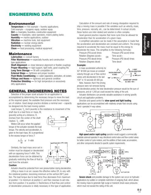
Selection of the proper sized actuator for an application is<br />
accomplished by determining the necessary torque to move the load<br />
at the required speed, the available fluid pressure and the necessary<br />
arc of rotation. Good design practice dictates a nominal over – capacity<br />
be designed into the load moving system.<br />
Load torque, T L (inch pounds) is the resistance to movement of the<br />
shaft due to a load force or mass, M,<br />
(pounds) acting at a distance, R,<br />
(inches) from the center of the shaft<br />
rotation. T L =MR.<br />
Motion will occur when the applied<br />
torque of the actuator exceeds the load<br />
torque. The velocity and acceleration, A,<br />
given to the load mass, M, is proportional<br />
to the excess torque or force, F.<br />
A= F M<br />
or<br />
F=MA<br />
Similarly, the load mass once set in<br />
motion must be stopped or decelerated<br />
with an opposing force F=MA. This<br />
deceleration force can be obtained by<br />
gradually restricting the flow of fluid to<br />
and from the actuator.<br />
Caution:<br />
Actuator should be protected from over pressurization during deceleration.<br />
Lifting a mass in an arc causes the effective radius ER, to vary with<br />
the rotational position, becoming minimum at the vertical (90°) position.<br />
The load torque due to load force thus decreases from maximum<br />
at position 1 to minimum at position 2, and then reverses to aid rotation<br />
from position 2 to position 3. Restrictions of fluid flow and control<br />
of deceleration pressures is vitally necessary in this type of application.<br />
Calculation of the amount and rate of energy dissipation required to<br />
stop a moving mass is possible if the variables such as velocity, mass,<br />
time, pressure, viscosity, etc., can be determined. In actual circuits<br />
these factors are inter-related and solution is often complex.<br />
Good general practice requires that more cycle time be allowed for<br />
deceleration than for acceleration of a given mass.<br />
A simplified calculation can be made if the assumption is made that<br />
the acceleration and deceleration are constant and uniform. The energy<br />
required to accelerate the mass must be equal to the energy to<br />
decelerate the mass. This simplifies to the following formulas:<br />
Pressure (PSI accel) times Pressure (PSI accel) times<br />
Rotation (Degrees accel)= Time accel=<br />
OR<br />
Pressure (PSI decel) times Pressure (PSI decel) times<br />
Rotation (Degrees decel)<br />
Time decel<br />
Example:<br />
A mass accelerated uniformly for<br />
50° @ 800 psi moves at constant<br />
velocity through use of flow-control<br />
valves until decelerated in the last<br />
100° in 10 seconds @ 400 psi.<br />
Note, however, that if the driving<br />
pressure were not removed during<br />
the deceleration period, the total deceleration pressure would be the sum of<br />
pressures, and at 1,200 psi could exceed the rating of the unit.<br />
Actuator distributors can provide valuable assistance in solving specific<br />
circuit and application problems.<br />
Direction and speed control for slow speed and light loading<br />
applications can be accomplished with relatively simple fluid circuits using<br />
hand- operated 4-way valves.<br />
High speed and/or rapid cycling operation would suggest a commercially<br />
available solenoid-operated 4-way directional control valve and flow-control valves<br />
for better control of cycle motions, and the addition of fluid cooler, accumulators,<br />
and other components directed to specific system requirements.<br />
Severe shock and possible damage to the system can occur on hydraulic<br />
applications by sudden or complete restriction of outgoing fluid, which allows<br />
the moving mass to generate high surge or transient shock wave pressures<br />
which must not exceed the rating of the unit.<br />
E-2<br />
4-96<br />
Engineering<br />
Data