DESCRIPTION OF PA / INTERCOM SYSTEM - Jefferson Lab
DESCRIPTION OF PA / INTERCOM SYSTEM - Jefferson Lab
DESCRIPTION OF PA / INTERCOM SYSTEM - Jefferson Lab

Create successful ePaper yourself
Turn your PDF publications into a flip-book with our unique Google optimized e-Paper software.
Intercom.doc 5/30/06<br />
Introduction<br />
<strong>DESCRIPTION</strong> <strong>OF</strong> <strong>PA</strong> / <strong>INTERCOM</strong> <strong>SYSTEM</strong><br />
Henry Robertson<br />
The basic consideration for having an intercom associated with the Personnel Safety System (PSS)<br />
is fast and direct communications. Although there is an assortment of devices (Run/Safe boxes,<br />
door interlocks, etc.) installed for quick shutdown of hazardous systems, a person to person link is<br />
necessary for evaluation of and response to emergency situations. A second but no less important<br />
reason is to inform and warn personnel of forthcoming hazardous situations. Also, there is a<br />
requirement to have an audible alert prior to beam operations. Since this system is for operational<br />
safety it is configured to primarily serve the needs of the Operation's Group.<br />
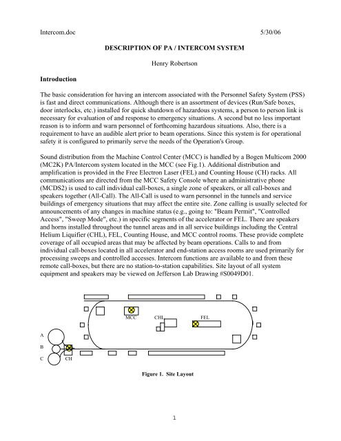
Sound distribution from the Machine Control Center (MCC) is handled by a Bogen Multicom 2000<br />
(MC2K) <strong>PA</strong>/Intercom system located in the MCC (see Fig.1). Additional distribution and<br />
amplification is provided in the Free Electron Laser (FEL) and Counting House (CH) racks. All<br />
communications are directed from the MCC Safety Console where an administrative phone<br />
(MCDS2) is used to call individual call-boxes, a single zone of speakers, or all call-boxes and<br />
speakers together (All-Call). The All-Call is used to warn personnel in the tunnels and service<br />
buildings of emergency situations that may affect the entire site. Zone calling is usually selected for<br />
announcements of any changes in machine status (e.g., going to: "Beam Permit", "Controlled<br />
Access", "Sweep Mode", etc.) in specific segments of the accelerator or FEL. There are speakers<br />
and horns installed throughout the tunnel areas and in all service buildings including the Central<br />
Helium Liquifier (CHL), FEL, Counting House, and MCC control rooms. These provide complete<br />
coverage of all occupied areas that may be affected by beam operations. Calls to and from<br />
individual call-boxes located in all accelerator and end-station access rooms are used primarily for<br />
processing sweeps and controlled accesses. Intercom functions are available to and from these<br />
remote call-boxes, but there are no station-to-station capabilities. Site layout of all system<br />
equipment and speakers may be viewed on <strong>Jefferson</strong> <strong>Lab</strong> Drawing #S0049D01.<br />
MCC CHL FEL<br />
A<br />
B<br />
C<br />
CH<br />
Figure 1. Site Layout<br />
1
Multicom 2000<br />
The MC2K is a programmable audio communication system that can handle up to 120 channels of<br />
audio signals. The core electronics mounted in an equipment rack (MC02B01) in Room-105 drives<br />
multiple audio amplifiers around the site which in turn feed the local speaker (see Fig.2). Some<br />
channels require fiber optic links to provide a high quality signal path over long distances. The<br />
circuit cards required for basic system operation include a single CPU card, and a set of three<br />
additional cards per 24 channels of intercom and <strong>PA</strong> functions. Each set consists of an Analog card,<br />
a Station card, and a Relay module. Two power supplies provide the +/- 5VDC, +/- 12VDC, and +/-<br />
26VDC required for system operation. Channels may by programmed individually for bi-directional<br />
communication between access rooms and the MCC, or they can be grouped together in up to eight<br />
zones for paging specific areas of the accelerator. Architectural numbers that match on-site<br />
locations can be assigned instead of using the default channel numbers. In special situations an All-<br />
Call (911) function is available that is pre-programmed to take priority over all channels for<br />
emergency announcements. The MC2K is programmed from the administrative phone in the MCC<br />
that has a LCD display for selecting options or it can be accessed through a serial port on the back<br />
panel of the card cage using a proprietary software package.<br />
MCC<br />
Administrative Multicom 2000 (MC2K)<br />
Phone (MCDS2) Power Amplifiers Speakers/Horns<br />
Intercom Call-boxes<br />
Injector Access<br />
N.Linac<br />
N. Linac<br />
N. Access<br />
S. Access<br />
S. Linac<br />
S. Linac<br />
BSY Access<br />
Fiber Optics<br />
BSY<br />
Hall A Access<br />
Hall A<br />
Hall B Access<br />
Hall C Access<br />
Hall B<br />
Hall C<br />
FEL Access<br />
FEL<br />
Figure 2. System Block Diagram<br />
System configuration and wiring details are available on <strong>Jefferson</strong> <strong>Lab</strong> Drawing S0065D01.<br />
2
Intercom.doc 5/30/06<br />
Processor Card<br />
The Processor Card (MCPCA2), installed in slot 1 (see Fig.4), controls all other cards in the system.<br />
One MCPCA2 is used per system regardless of system size and no other card may be installed in<br />
this slot. It contains the microprocessor, dual-tone-multiple-frequency (DTMF) encoder, memory,<br />
and system clock. The DTMF encoder converts the switch signal of a call-box to a tone pattern that<br />
calls the administrative phone and shows an extension number. A system clock updates the<br />
day/time readout on this phone and an EPROM memory holds the settings for the system<br />
configuration.<br />
Analog Card<br />
The Analog Card (MCAC) which handles 24 channels is installed in slot 2 (see Fig.4) and every<br />
even slot thereafter. It contains a 20 watt program amplifier, a 12 watt intercom amplifier, and relay<br />
control circuits. The +/-26V power buses are indicated by two LEDs on the card's edge. Each bus is<br />
fused with a 1-amp plug-in fuse that is replaceable by the user. This card provides all program preamplification<br />
and intercom talk-back amplification and includes controls for paging volume(R30),<br />
talk-back volume (R75), compression level(R120), speaker volume(R53), and switching sensitivity<br />
(R119) and delay (R118) (see Fig.3). The switching sensitivity and delay adjustment controls the on<br />
board voice operated transmission (VOX) circuit. This allows the user in an access room to speak<br />
"hands-free" once the call button is pressed on a call-box. The sensitivity adjustment sets the point<br />
that the circuit switches from talk to talk-back modes. The delay control allows pauses between<br />
words without switching modes mid-sentence. To make adjustments to these controls the MCAC<br />
must first be inserted into an extender card.<br />
1-amp fuses<br />
-26V<br />
+26V<br />
R30 R120 R118 R75 R119 R53<br />
Figure 3. Analog Card Adjustments<br />
3
Station Card<br />
The Station Card (MCSC) which also handles 24 channels is installed in slot 3 (see Fig.4) and every<br />
odd slot thereafter. It contains the cross-point switches, and DTMF decoder. This card handles the<br />
telephonic switching between stations. The cross-point switching circuit allows connection of any<br />
channel configured as an input to any channel or group of channels configured as outputs. The<br />
DTMF decoder converts a signal from the analog tone input to a 4-bit output in hex. There must be<br />
a Station Card associated with each Analog Card. There are no user adjustments on this card, but<br />
the +12V bus is indicated by an LED and fused by a 1-amp plug-in fuse.<br />
Relay Module<br />
The Relay Module (MCRM) for each set of 24 channels is installed above the card-cage on the rack<br />
mounting rails. One Relay Module is required for each Analog/Station Card pair installed (see<br />
Fig.4). It is connected to these cards with ribbon cable though the card cage back plane. This<br />
module connects to all program sources, administration and call-boxes, speakers, and amplifiers.<br />
These audio inputs / outputs are connected via 4-pin Molex right-angle headers labeled J1 - J25. J1<br />
is reserved for the MCDS2 phone input. The remaining channels J2-J25 can be mixed inputs or<br />
outputs as needed. No more than 250 watts of power (10 watts/channel) may be used per module. In<br />
our operation an 80 watt booster amp is connected at RCA1 and J39 on the Relay Module. This<br />
amp boosts the sound level (~ 3 watts/channel) to the call-boxes using a 25V constant voltage<br />
output.<br />
Relay Module 2 (Ch.25 - 48)<br />
Relay Module 1 (Ch.1 - 24)<br />
Cardcage<br />
Slot 5 - Station Card 2 MCSC (Ch.25 - 48)<br />
Slot 4 - Analog Card 2 MCAC (Ch.25 - 48)<br />
Slot 3 - Station Card 1 MCSC (Ch.1 - 24)<br />
Slot 2 - Analog Card 1 MCAC (Ch.1 - 24)<br />
Slot 1 - Processor Card MCPCA2<br />
Figure. 4 MC2K Cardcage and Module Layout<br />
4
Intercom.doc 5/30/06<br />
Administrative Phone<br />
The Administrative Phone (MCDS2) is a modified telephone handset that communicates with the<br />
Processor Card with DTMF tones similar to a typical home phone, but with special system calling<br />
features. It is used as the central phone for making announcements and calls on the <strong>PA</strong>/intercom<br />
system. This unit consists of a speaker-phone with an alpha-numeric display. The display shows the<br />
time and day, the incoming call queue, and the programming functions when selected. The keypad<br />
is a standard 12-button type with additional pushbuttons available for setup of speed-dialing,<br />
speaker-phone, and volume settings. System functions are accessed with the standard keypad and<br />
range from setting the time to full system configuration. With proper key-entry and passwords a<br />
menu is displayed for setting system parameters. This phone is connected to channel 01 (the<br />
reserved channel) on the Relay Module.<br />
Distributed Audio Signals<br />
Each output channel from the Multicom used for <strong>PA</strong> is sent through an impedance matching<br />
transformer (see Fig.5). These transformers (TLA-25) match the 25V constant voltage output from<br />
the Relay Module to standard 600 ohm line level audio. In the North and South Linacs the<br />
transformers are then tied directly to the power amps as balanced inputs. The channels assigned to<br />
the Beam Switchyard, Hall B, and Hall C are tied to fiber optic transmitters in the MCC and sent<br />
over fiber to the equipment racks on the second floor of the Counting House. At this point they are<br />
converted back to twisted-pair and then connected to the power amps as unbalanced inputs. The<br />
FEL amplifiers are located in the FEL equipment room (zone 15) and are configured similarly to the<br />
endstation systems.<br />
MCC<br />
Administrative<br />
Phone (MCDS2)<br />
Bogen Multicom System (MC2K)<br />
Matching Transformer<br />
25V<br />
600 ohm<br />
Voltage Constant Line level signal<br />
voltage drive<br />
Fiber Optic TX<br />
Access Room<br />
Call-boxes<br />
Fiber<br />
Trunk<br />
<strong>PA</strong> Speakers<br />
70V<br />
Constant<br />
voltage drive<br />
Power Amplifier<br />
600 ohm<br />
Line level signal<br />
Fiber Optic RX<br />
Figure 5. Typical <strong>PA</strong>/Intercom Channel<br />
5
The power amps from University Sound range from 35 to 150 watts of output power (see Fig.6).<br />
They can drive either low or high impedance speakers. The high impedance / constant voltage<br />
output at 70.7V is used because it provides some important advantages. Smaller gauge cable can be<br />
run over longer distances and can connect to a larger number of speakers in each area. Each<br />
amplifier is capable of handling at least three types of inputs. Currently, only the line and<br />
microphone inputs are used, however in the near future the program input will be used for<br />
prerecorded messages. The front panel controls consist of individual channel and master level<br />
settings with a bar-graph LED display. Treble and base controls can each be adjusted for 12dB of<br />
boost or cut. If the EQ switch is set to "defeat", these tone controls are bypassed and no equalization<br />
is added to the signal. Each input can be attenuated with a rear panel gain control. The overall level<br />
(the combination of individual channels and the master control) should not read over 0dB on the<br />
bargraph, otherwise distortion may occur.<br />
Bargraph Display<br />
Input Volume Bass Treble EQ Master Power<br />
Figure 6. Typical <strong>PA</strong> Amplifier<br />
In the tunnel, speakers are of a low impedance type that use a matching transformer to tie them to<br />
the high impedance line. They are mounted in aluminum bi-directional baffles suspended from the<br />
ceiling. Horns have been installed in the service buildings to compensate for the noise level of<br />
equipment and are either single or bi-directional. They are made of steel and fiberglass and have<br />
weather sealed switches. Both the speakers and horns have a selection of taps for power levels<br />
ranging from 1 to 25 watts depending on the type. This allows balancing of sound in areas with<br />
different ambient noise levels. The total power setting of all of the speakers and horns must be less<br />
than the amplifier's rated output in order to keep the total load impedance higher than or equal to its<br />
output impedance.<br />
Hall A Configuration<br />
The Hall A audio system is an exception to that just specified. Originally this installation matched<br />
those in halls B and C which consist of horns mounted around the perimeter facing toward the<br />
center of the hall. However, this configuration proved not to be adequate for delivering clear speech<br />
throughout the area (Fig.7). Tests were made to determine what type of amplifier/speaker<br />
combination would compensate for the poor acoustics in the hall and provide the best intelligibility<br />
for operational announcements. An energy time curve (ETC) test was performed using a Time-<br />
6
Intercom.doc 5/30/06<br />
Energy-Frequency (TEF) Analyzer with Electrical Acoustical Simulation For Engineers (EASE)<br />
software. The RT60 data for voice intelligibility (1KHz to 3KHz) showed an average of 5.25<br />
second reverb time and up to 10 seconds in certain locations. "RT60" is the measurement of how<br />
long (in seconds) it takes a sound to decay 60dB. In another test, %Alcons, a 75% rating was<br />
measured. "%Alcons" is a percentage measurement of the "loss of consonants" when a hypothetical<br />
standard speech test is given. The direct-to-reverberant ratio of the sound system's transmitted<br />
acoustic signal is measured together with the early decay time. When these two measurements were<br />
combined the results showed that proper speech reinforcement in the hall would be very<br />
problematic. Additionally, the ambient noise level ranged from around 77dBa without activity to<br />
81dBa with the crane running and extended even higher with a fork-lift in operation.<br />
Figure 7. Pattern Dispersion of the Original Hall A <strong>PA</strong> System<br />
The final design (Fig.8) was limited in the location of its installation due to conflicts with the preinstalled<br />
experimental equipment and yet the result was better overall sound coverage than<br />
previously possible (Fig.9). Large low-impedance JBL drivers (2485J) and bi-radial horns (four<br />
2385A and one 2382A) are centrally mounted in the dome area on the crane support. The 2385As<br />
each producing a 60x40 degree pattern are aimed outward at 45 degrees, while the 2382a producing<br />
a 120x40 degree pattern is directed toward the floor. They are all driven by two Crown amplifiers<br />
(CT410), and a Shure equalizer (DFR-11EQ) configured to compensate for the extreme<br />
reverberation. One of the amplifiers also drives the 70.7V speakers and horns in the Hall A<br />
Counting Room and in the truck ramp.<br />
7
Audio Line<br />
IN<br />
CT-410<br />
(4) 2385A<br />
Low OUT<br />
Audio Bus OUT<br />
DFR-11EQ<br />
Bus IN<br />
Low OUT<br />
IN CT-410 Low OUT (1) 2382A<br />
70V OUT<br />
Figure 8. Hall A Amplifier Configuration<br />
Figure 9. Pattern Dispersion of Final Installation<br />
8
Intercom.doc 5/30/06<br />
Call-boxes<br />
There are call-boxes in every accelerator and end-station access room. These are basically just a<br />
speaker and a call button enclosed in a box. The intercom circuits are 25V constant voltage type<br />
requiring each speaker to have a matching transformer which come with power level taps that range<br />
from 1/2 to 2 watts. To communicate with the MCC from an access room, the local pushbutton is<br />
pressed momentarily. This activates the call circuit for that channel on the relay module. The CPU<br />
card then routes the call to the administrative phone on the safety console in the MCC which rings<br />
and displays the calling channel. Once the handset is picked up, the person in the access room can<br />
talk hands-free. This is accomplished through the voice activated (VOX) circuit on the Analog<br />
Card.<br />
Fiber Optics<br />
Fiber optics are used to transport low-level audio signals over long distances. The XA-1800BA<br />
Fiber Optic Transmitter converts the audio signal to light for transmission over fiber optic cables<br />
using linear, intensity modulation (IM). IM is the variation of optical power level of an optical<br />
carrier in unison with an applied modulated signal. This is similar to amplitude modulation (AM) of<br />
an RF carrier. The transmitter employs a balanced transformer-coupled input that includes an<br />
adjustable input attenuator for signals above the recommended 1-volt RMS. The companion<br />
receiver, the RA-1800BA, converts the modulated light back into a duplicate of the original<br />
transmitted signal. It is designed with an internal output transformer to drive balanced loads, and it<br />
has an output level control that is used to compensate for optical attenuation.<br />
Back-up System<br />
In case of a system failure of the Multicom an additional method is installed to handle emergency<br />
paging (see Fig.10). A microphone located in the back of rack MC02B28 in the MCC control room<br />
is connected to the power amps throughout the site. This system requires a variety of modules that<br />
distribute the microphone signal to the amplifiers. Initially the audio signal goes into a microphone<br />
distribution amplifier (STM-DA3) that provides up to three balanced outputs. These are connected<br />
to low-noise microphone pre-amps (STM-2) to boost the signal level. The multiple outputs of the<br />
pre-amps are then connected to resistive branching networks (STD-600) that fan out the signal to<br />
the appropriate power amplifiers. The audio going to the North and South Linacs is connected<br />
directly to the respective amplifier's microphone input. The audio signals going to the FEL, BSY,<br />
and the end-stations are converted to fiber optic signals, transmitted, and converted back to twisted<br />
pair then fed into the amps for those areas. In the back-up mode the <strong>PA</strong> system cannot handle twoway<br />
intercom communications with the access rooms, nor does it have zone selection capability. It<br />
will only deliver All-Calls throughout the site.<br />
9
MCC<br />
Microphone STM-DA3 STM-2 STD-600 Fiber Optic TX<br />
600 ohm<br />
Line level signal<br />
<strong>PA</strong> Speakers<br />
Fiber<br />
Trunk<br />
70V<br />
Constant<br />
voltage drive<br />
Power Amplifier<br />
600 ohm<br />
Line level signal<br />
Fiber Optic RX<br />
Figure 10. Typical <strong>PA</strong> Back-up Channel<br />
General Use<br />
To call a staff phone or make an announcement, the 3-digit architectural number assigned to that<br />
channel is dialed or the appropriate speed-dial button is selected. Pressing [911] will select all<br />
stations and broadcast the announcement throughout the site (this is usually reserved for emergency<br />
announcements). The current list of numbers is given in Appendix A. When a staff phone or <strong>PA</strong><br />
speaker is called, a notification beep is heard at the remote location prior to any messages. This<br />
attracts the attention of the listener to any incoming announcements. The control room is notified of<br />
a call originating from an access room when the MCDS2 phone rings. Call-boxes have hands-free<br />
voice operation once the call-in button is pressed. When answering these calls in the MCC, lifting<br />
the handset automatically connects to the first number on the display. If more calls arrive while the<br />
phone is in use, the phone will ring and place the calls in a queue. The first caller in the queue can<br />
be recalled automatically by pressing the star key [*] twice. Any call in the queue may be selected<br />
by pressing the pound key [#] once to access scroll mode then press it repeatedly until the desired<br />
number is selected. When that number is at the top of the queue, it can then be automatically called<br />
by pressing [*] twice. The call-waiting queue may be cleared by pressing the sequence [# * 1]. As<br />
there are high-noise levels and/or extended reverberations in certain areas of the site, all<br />
announcements should be spoken slowly and pronounced clearly.<br />
10
Intercom.doc 5/30/06<br />
Troubleshooting<br />
When tracking down a problem always start with the simplest probable solution and work toward<br />
the more complex. If the problem seems to affect only a portion of a system, start debugging at the<br />
field device level. If a complete system appears to have failed, start looking for problems at the rack<br />
equipment level. Below is a list of common problems found with the MC2K system. These will be<br />
updated as new problems and solutions are found.<br />
Problem:<br />
Sensitivity to voltage surges during thunderstorms and power outages.<br />
The symptoms may range from no display on the administrative phone to no dial tone or<br />
continuous beeping from the handset.<br />
Solutions:<br />
Cycle power on the Multicom card-cage. Open the back door of rack MC02B01 and note the<br />
power cord labeled MC2K near the bottom of the power strip. Unplug this cord for 5<br />
seconds and then replace it. Check for proper operation.<br />
Replace the Station Card fuse. Power must be removed from the card-cage as described<br />
above before removing the card. Refer to the previous section about this card in order to<br />
locate the proper card slot and position of the fuse. These are accessed from the front of the<br />
rack. Spare fuses are kept in the documentation folder inside the front door of this rack.<br />
Reinstall the card, power up the rack, and check for proper operation.<br />
Replace the Station Card. Follow the procedures above for removing the card. Spare cards<br />
are kept in the PSS locker #4 in building #89. Replace the card, power up the rack, and<br />
check for proper operation.<br />
11
Future Upgrades<br />
In order to improve intelligibility in the end-stations and other high noise areas, an effort is being<br />
made to digitize all of Operations' standard announcements. These could include beam-state<br />
changes, evacuation warnings, and others. To accomplish this a variety of methods have been<br />
researched and eliminated due to complexity and cost.<br />
The method chosen uses a computer (PC) to send messages to the PSS intercom system (see Fig.<br />
11). A Visual Basic program was written to provide a user interface that allowed operators to select<br />
and play a desired message. These messages are prerecorded and saved on a hard drive as Wave<br />
files (.wav format). To make a connection between the computer and the intercom system requires<br />
installing a Telephone Applications Program Interface (TAPI) compatible modem in the PC and a<br />
telephone interface card (MCTC) in slot 11 of the MC2K cardcage. This is not a direct connection.<br />
Each side needs its own analog line, and the two communicate via the POTS (Plain Old Telephone<br />
System).<br />
Personal<br />
Computer<br />
Telephone<br />
System<br />
TAPI Compliant<br />
Modem<br />
POTS lines<br />
<strong>PA</strong> System’s<br />
Control Electronics<br />
Speaker or<br />
zone of<br />
speakers<br />
Matrix<br />
Switch<br />
Telephone<br />
Interface<br />
Figure 11. PC to Intercom System, Overview.<br />
12
Intercom.doc 5/30/06<br />
The Auto-Announce program is available from the pop-up task bar at the bottom of the screen. The<br />
user screen (see Fig. 12) is small so as not to block large areas of the PSS status screen that may be<br />
in use. This screen will open in the center of the display, but can be moved by the operator if<br />
needed. This screen includes the “Segments” drop-down menu, a hang-up pushbutton, and a status<br />
bar. Clicking on the pushbutton will hang up the telephone line to the <strong>PA</strong> system and stops any<br />
operations in progress. The status bar shows the time and date, and displays any messages from the<br />
program.<br />
Disconnect Line<br />
Pushbutton<br />
Figure 12. Initial Auto-Announce Screen<br />
Status Bar<br />
To play a message, one must first select the segment of interest by clicking on the menu (see<br />
Fig.13). When an area is chosen, a window for that segment pops up and allows the user to select a<br />
message by clicking on a drop-down list (see Fig. 14).<br />
Figure 13. Drop-down Menu For Selecting Segment.<br />
Figure 14. Segment Window With Message Drop-down List.<br />
13
When a message is selected, the program will play the associated file through the intercom system<br />
to a pre-configured set of speakers. The announcement will take a few seconds to start and will play<br />
twice. When the message ends the program automatically closes the selected segment screen and<br />
allows the user to make another selection. Only one segment window can be open at a time, and<br />
only one message can be selected at a time. When done the Auto-Announce screen should not be<br />
closed, but instead, minimized for future use.<br />
14