DESCRIPTION OF PA / INTERCOM SYSTEM - Jefferson Lab
DESCRIPTION OF PA / INTERCOM SYSTEM - Jefferson Lab
DESCRIPTION OF PA / INTERCOM SYSTEM - Jefferson Lab

Create successful ePaper yourself
Turn your PDF publications into a flip-book with our unique Google optimized e-Paper software.
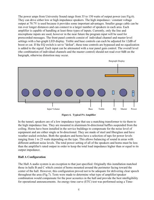
The power amps from University Sound range from 35 to 150 watts of output power (see Fig.6).<br />
They can drive either low or high impedance speakers. The high impedance / constant voltage<br />
output at 70.7V is used because it provides some important advantages. Smaller gauge cable can be<br />
run over longer distances and can connect to a larger number of speakers in each area. Each<br />
amplifier is capable of handling at least three types of inputs. Currently, only the line and<br />
microphone inputs are used, however in the near future the program input will be used for<br />
prerecorded messages. The front panel controls consist of individual channel and master level<br />
settings with a bar-graph LED display. Treble and base controls can each be adjusted for 12dB of<br />
boost or cut. If the EQ switch is set to "defeat", these tone controls are bypassed and no equalization<br />
is added to the signal. Each input can be attenuated with a rear panel gain control. The overall level<br />
(the combination of individual channels and the master control) should not read over 0dB on the<br />
bargraph, otherwise distortion may occur.<br />
Bargraph Display<br />
Input Volume Bass Treble EQ Master Power<br />
Figure 6. Typical <strong>PA</strong> Amplifier<br />
In the tunnel, speakers are of a low impedance type that use a matching transformer to tie them to<br />
the high impedance line. They are mounted in aluminum bi-directional baffles suspended from the<br />
ceiling. Horns have been installed in the service buildings to compensate for the noise level of<br />
equipment and are either single or bi-directional. They are made of steel and fiberglass and have<br />
weather sealed switches. Both the speakers and horns have a selection of taps for power levels<br />
ranging from 1 to 25 watts depending on the type. This allows balancing of sound in areas with<br />
different ambient noise levels. The total power setting of all of the speakers and horns must be less<br />
than the amplifier's rated output in order to keep the total load impedance higher than or equal to its<br />
output impedance.<br />
Hall A Configuration<br />
The Hall A audio system is an exception to that just specified. Originally this installation matched<br />
those in halls B and C which consist of horns mounted around the perimeter facing toward the<br />
center of the hall. However, this configuration proved not to be adequate for delivering clear speech<br />
throughout the area (Fig.7). Tests were made to determine what type of amplifier/speaker<br />
combination would compensate for the poor acoustics in the hall and provide the best intelligibility<br />
for operational announcements. An energy time curve (ETC) test was performed using a Time-<br />
6