

![[PDF] JCI Gage Standards - Johnson Controls Inc.](https://img.yumpu.com/23687663/1/500x640/pdf-jci-gage-standards-johnson-controls-inc.jpg)
[PDF] JCI Gage Standards - Johnson Controls Inc.
[PDF] JCI Gage Standards - Johnson Controls Inc.
[PDF] JCI Gage Standards - Johnson Controls Inc.

Create successful ePaper yourself
Turn your PDF publications into a flip-book with our unique Google optimized e-Paper software.
<strong>Johnson</strong> <strong>Controls</strong> Automotive Experience<br />
Global Supplier <strong>Standards</strong> Manual<br />
Chapter 2<br />
Tooling & Equipment<br />
(December 1, 2012)<br />
<strong>JCI</strong> <strong>Gage</strong> <strong>Standards</strong><br />
<strong>Johnson</strong> <strong>Controls</strong> and Supplier Managed <strong>Gage</strong>s<br />
This manual is for the intended use of the employees and suppliers of <strong>Johnson</strong> <strong>Controls</strong>, <strong>Inc</strong>. and is considered to be a PROPRIETARY<br />
DOCUMENT. Any distribution or sharing of this document is prohibited. All copies must be obtained from the <strong>Johnson</strong> <strong>Controls</strong> <strong>Gage</strong><br />
Engineer.<br />
Uncontrolled if printed
TABLE OF CONTENTS<br />
Introduction 1<br />
Scope 2<br />
General Requirements 3<br />
Safety and Ergonomic Requirements 4<br />
Quotation Requirements 6<br />
<strong>Gage</strong> Design Requirements 7<br />
A. Concept Drawing 7<br />
B. <strong>Gage</strong> Design 7<br />
<strong>Gage</strong> Build Requirements 9<br />
A. Bases 9<br />
B. Tooling Balls / Tooling Holes 9<br />
C. Risers and Stanchions 9<br />
D. Details 9<br />
E. Removable Details 10<br />
F. Hinged Details 10<br />
G. Locating Pins 10<br />
H. Clamps 10<br />
I. Scribe Lines / Tolerance Bands 10<br />
J. SPC Indicators 11<br />
K. Build Tolerances 11<br />
L. Labeling 12<br />
M. Corrosion Protection 12<br />
N. <strong>Gage</strong> Certification 13<br />
O. Third Party Certification 13<br />
P. <strong>Gage</strong> Instructions 13<br />
Q. Function Check 13<br />
R. Measurement Systems Analysis 14<br />
S. Shipping / Transportation 15<br />
T. Preventive Maintenance Instructions 15<br />
U. <strong>Gage</strong> Records 15<br />
V. Specialty Gaging 16<br />
W. Automated and Semi-Automated Gaging 16<br />
Appendices 17<br />
A. Appendix A – Documents 17<br />
B. Appendix B – Diagrams 40<br />
C. Appendix C – Standard Materials List 68<br />
D. Appendix D – Revision Table 69<br />
E. Appendix E – Reference List 71<br />
F. Appendix F – Glossary of Terms 72<br />
Revision Level: 005 – 12/01/12 1
Go to Table of Contents<br />
INTRODUCTION<br />
TO OUR PARTNER GAGE SUPPLIERS<br />
In today’s global automotive industry, it is essential for a company’s commitment to provide its customers with a high<br />
quality and defect-free part that is delivered on time. This can be quite a challenge due to the ever-changing<br />
requirements set forth by our customers. Yet, this is the expectation of our customers. Some companies struggle to<br />
maintain this high quality by implementing so-called “quick fix” strategies. These are only temporary. <strong>Johnson</strong> <strong>Controls</strong><br />
maintains that in order to supply our customers with these high quality parts we have to implement long-term strategies<br />
that are industry proven. One of these strategies is the Partnership Supplier program. This program is crucial for the<br />
success of <strong>Johnson</strong> <strong>Controls</strong>. We know we cannot do it alone and therefore have to rely on our suppliers to help us. We<br />
feel it is, and always will be, a TEAM EFFORT.<br />
The intent of this manual is to define the <strong>Johnson</strong> <strong>Controls</strong>’ requirements for gages and fixtures. It also goes beyond the<br />
simple design and build requirements and sets forth other requirements for our Partner <strong>Gage</strong> Supplies. Since <strong>Johnson</strong><br />
<strong>Controls</strong> has many customers, it is important to understand that our manual is to be used as a guide in conjunction with<br />
our customers’ standards. The intent is also to supersede any customer requirements that are more lenient but to<br />
utilize any customer requirements that are more demanding. We understand that all customer requirements are<br />
different, but we believe that by using this manual, there will be less confusion and more consistency in designing and<br />
building gages for <strong>Johnson</strong> <strong>Controls</strong>. The intent of this manual IS NOT to dictate the process of HOW to build a gage but<br />
to GUIDE you in completing your task.<br />
While this manual sets forth certain minimum gage and procedural requirements, it is not intended to be absolute. It is<br />
both <strong>Johnson</strong> <strong>Controls</strong>' and the Partner <strong>Gage</strong> Suppliers’ responsibility to continuously improve and to be objective in its<br />
approach to any gage program. Therefore, your independent analysis of our requirements and suggested changes or<br />
improvements are welcomed. We do ask, however, that any proposed deviation from this manual be approved by the<br />
<strong>Johnson</strong> <strong>Controls</strong> <strong>Gage</strong> Engineer prior to its incorporation.<br />
Your responsibility in our TEAM is a large one. The quality, functionality, value and timeliness of these gages are a direct<br />
reflection of your company. As a Partner, you have to not only show the expertise in your field, but also provide<br />
invaluable assets like integrity, dependability and ingenuity. <strong>Johnson</strong> <strong>Controls</strong>, in its effort to select the BEST Partner<br />
<strong>Gage</strong> Suppliers, recognized not only these assets in your company, but also a desire to be a member of the JOHNSON<br />
CONTROLS TEAM.<br />
We value the “Partnership” that has been established. We appreciate your efforts.<br />
Sincerely<br />
Doug Stewart<br />
<strong>Gage</strong> Engineer<br />
<strong>Johnson</strong> <strong>Controls</strong>, <strong>Inc</strong>., North American Automotive Group<br />
By signing below, the <strong>Gage</strong> Supplier acknowledges the receipt of this manual and also agrees to comply with its contents.<br />
_________________________ _________________________ _________________________<br />
Astronetics CG Model and Fixture Jay-Enn<br />
_________________________ _________________________ _________________________<br />
MetroCal Michigan <strong>Gage</strong> Specialties MP Components<br />
Revision Level: 005 – 12/01/12 2
Go to Table of Contents<br />
SCOPE<br />
This <strong>Gage</strong> Standard applies to all of <strong>Johnson</strong> <strong>Controls</strong> North American Automotive Group and its Partner <strong>Gage</strong> Suppliers.<br />
This <strong>Gage</strong> Standard establishes requirements for gages and fixtures that are used in conjunction with the inspection,<br />
measurement, and evaluation of the part. Such gages and fixtures are Attribute gages, SPC gages, CMM holding fixtures<br />
or any combination of the previously mentioned. Generally, gages and fixtures are defined as:<br />
FIXTURE<br />
<br />
GAGE<br />
<br />
A device that is used to hold one or more parts while various operations are performed. For instance, a<br />
fixture is used to hold the part while an inspection is performed.<br />
An instrument that is used to measure the part. For instance, a gage is a fixture with an Attribute rail or SPC<br />
indicator port attached to it.<br />
PLEASE NOTE: The terms fixture and gage are commonly referred to as the same piece of<br />
equipment. A fixture and a gage can be the same, but not always. If the measuring instrument is<br />
not attached to the holding device, then it is only a fixture [CMM holding fixture], whereas, if the<br />
measuring instrument is attached to the holding device [Attribute gage, SPC gage], it becomes a<br />
gage.<br />
This <strong>Gage</strong> Standard does not establish requirements for jigs, assembly fixtures, milling fixtures, assembly nests, headliner<br />
tub fixtures, calipers, micrometers and the like. It does, however, provide instructions or guidelines that could be used<br />
with these types of equipment.<br />
Please note the following terms and their definitions as they are used in this document:<br />
Term<br />
<strong>JCI</strong> representative<br />
<strong>Gage</strong> Engineer<br />
Supplier<br />
Definition<br />
<strong>Johnson</strong> <strong>Controls</strong> North American Automotive Group representative<br />
<strong>Johnson</strong> <strong>Controls</strong> North American Automotive Group <strong>Gage</strong> Engineer<br />
<strong>Gage</strong> Supplier<br />
Revision Level: 005 – 12/01/12 3
Go to Table of Contents<br />
GENERAL REQUIREMENTS<br />
1. The Supplier must quote in compliance with the Reliability and Maintainability requirements as stated on the <strong>Gage</strong> Request for<br />
Quote or the <strong>Gage</strong> Assumptions / <strong>Gage</strong> Cost Model form. If these requirements cannot be met, the Supplier must either “no quote”<br />
the job or obtain a written deviation from the <strong>JCI</strong> representative.<br />
2. Receipt of the hardcopy purchase order does not represent the start date of the work to be completed. The start date will be<br />
established when the purchase order number is sent via e-mail (or verbally) or the receipt of the CAD model or prints, whichever is<br />
later. The start date plus the quoted timing will establish the gage delivery date. All deviations from the delivery date must be<br />
communicated to the <strong>Johnson</strong> <strong>Controls</strong>’ team in writing. Only circumstances fully outside of the Supplier's control will be<br />
considered as acceptable program delays.<br />
3. All work that is started without a purchase order number and/or CAD model will be the Supplier’s responsibility if the program is<br />
delayed or canceled.<br />
4. The Supplier is responsible for the accuracy of all gages. Work resulting from the use of “out of calibration” equipment or defective<br />
processes will be the Supplier’s responsibility and must be corrected without cost to <strong>Johnson</strong> <strong>Controls</strong>. This includes the<br />
equipment and processes for any sub-suppliers. Return to <strong>Gage</strong> Build Requirements – Section A. <strong>Gage</strong> Certification, item #1<br />
5. If a gage was used to qualify a part or process and the it was found to be in error (i.e. built or certified with equipment that is out of<br />
calibration, a net surface is cut to the wrong side of material, etc.), the Supplier may be charged for prevailing layout cost, air freight<br />
part shipment charges, labor charges and/or other charges directly related to the discrepant gage. In addition, if a tool has been<br />
modified using a gage that was not dimensionally correct, the Supplier will be charged for the tool work to correct the part. <strong>Johnson</strong><br />
<strong>Controls</strong> will make every effort to ensure the gages are re-verified within the same parameters (temperature, humidity) as the<br />
Supplier. To ensure that equipment changes are not done hastily or needlessly, the <strong>JCI</strong> representative must allow the Supplier to<br />
re-verify the gage before any changes are initiated. If there is a question or concern, the <strong>JCI</strong> representative, the Supplier and the<br />
<strong>Gage</strong> Engineer will meet to resolve the issue. Return to <strong>Gage</strong> Build Requirements – Section A. <strong>Gage</strong> Certification, item #1.<br />
6. The Supplier is responsible for part to gage clearance issues regardless of when parts are available. If the gage is shipped to<br />
<strong>Johnson</strong> <strong>Controls</strong> prior to part availability, the return shipping cost will be <strong>Johnson</strong> <strong>Controls</strong>’ responsibility.<br />
7. All gages must be warranted against manufactures’ defects for the life of the program. Warranty items may consist of substandard<br />
materials, poor labeling or any items that may cause bodily injury. Any detail in need of repair or replacement due to operator<br />
error, poor maintenance, or overall neglect is not considered warranty items. If a warranty item is in question, it will be brought to<br />
the <strong>Gage</strong> Engineer’s attention and decided upon jointly, between the <strong>Gage</strong> Engineer, the <strong>JCI</strong> representative, and the Supplier.<br />
8. Throughout the life of the program, the Supplier may be requested to provide a cost breakdown for quoted and/or completed work.<br />
The <strong>Johnson</strong> <strong>Controls</strong> <strong>Gage</strong> Cost Breakdown form must be used to supply this information.<br />
9. No fixtures will be modified from the original design without the prior consent of the <strong>JCI</strong> representative.<br />
10. If a gage is to be used in a country other than the continental United States, all labeling and documentation must be in English and<br />
the respective native language. The <strong>Gage</strong> Request for Quote or the <strong>Gage</strong> Assumptions / <strong>Gage</strong> Cost Model form will indicate<br />
whether or not international labeling and documentation is required, but the <strong>JCI</strong> representative will make the final determination of<br />
which specific labels or documents are to be translated. The <strong>JCI</strong> representative will assist in the translations as required.<br />
11. If <strong>Johnson</strong> <strong>Controls</strong> provides or assists in the development of new or innovative devices or techniques, the Supplier may not<br />
disclose this information (verbal or tangible) to anyone outside of <strong>Johnson</strong> <strong>Controls</strong> without the written permission of the <strong>Gage</strong><br />
Engineer. This shall prevail for a period of three years after delivery of the gage. All trade secrets and/or patent rights are the<br />
property of <strong>Johnson</strong> <strong>Controls</strong>.<br />
12. A Supplier shall not share any photograph or video images of any <strong>Johnson</strong> <strong>Controls</strong> gages with anyone outside of <strong>Johnson</strong><br />
<strong>Controls</strong> without the written permission of the <strong>Gage</strong> Engineer. All images are the property of <strong>Johnson</strong> <strong>Controls</strong>.<br />
Go to Glossary of Terms<br />
Revision Level: 005 – 12/01/12 4
Go to Table of Contents<br />
SAFETY AND ERGONOMIC REQUIREMENTS<br />
1. Every effort must be made to design and manufacture a gage or fixture that is operator friendly. Safety is top priority at <strong>Johnson</strong><br />
<strong>Controls</strong> and it must be carried over into the equipment that is purchased. If an ergonomic issue is in question after a fixture is built<br />
then the <strong>JCI</strong> representative and Supplier must determine the course of action and financial responsibility. If agreement cannot be<br />
made the <strong>Gage</strong> Engineer will arbitrate.<br />
2. The entire gage must be free of any sharp edges, or burrs, paying very close attention to the “operators area of movement.”<br />
3. Attention must be given when purchasing or designing and building toggle clamps, hinge drops, and other movable details that can<br />
pinch the operator. Clamps that are free of pinch points must be used whenever possible.<br />
4. Toggle Clamps and hinged drops must have mechanisms installed that prevent free falling onto the operator (handle stops, toggle<br />
clamp lockout, hinge drop lockout). This pertains not only in its built position but also if it will be rotated into a different orientation<br />
for inspection purposes.<br />
5. Every effort must be taken to ensure that any removable detail does not exceed 40-lbs. In those circumstances the 40-lb. weight is<br />
exceeded, assist devices such as counter balances must be used. Also, considerations must be given to the ease of removal and<br />
assembly of these details. Hand cutouts, handles, forklift sleeves or eyebolts must be installed whenever possible.<br />
6. The following weight restrictions apply:<br />
<br />
<br />
<br />
<br />
Fixtures < 40 pounds must have two (2) handles installed.<br />
Fixtures > 40 pounds but < 65 pounds must have four (4) handles installed.<br />
Fixtures > 65 pounds but < 300 pounds must have a dedicated cart or table with casters.<br />
Fixtures > 300 pounds must have eyebolts or forklift sleeves installed.<br />
NOTE: The <strong>JCI</strong> representative is responsible to determine the method of procurement (internal fabrication,<br />
manufacturing plant purchase or Supplier fabrication) for the cart or table. Also, regardless of procurement<br />
method, the cart must be designed and fabricated with full and direct support on center of the fixture (center<br />
pillar with caster or leveling jack).<br />
7. As a general practice, all handles that are attached to a gage should have a minimum grip length of 4”, a minimum grip width of 1”,<br />
and minimum hand access height of 1”.<br />
8. The Supplier must make every effort to incorporate or allow for the following ergonomic information when designing and building a<br />
gage:<br />
Operator<br />
(See anthropometric chart below)<br />
<strong>Gage</strong> design<br />
<strong>Gage</strong> efficiency<br />
(Operator motion efficiency)<br />
Arm reach Inspection tool placement Task / operation time<br />
Work envelope Proper clearances Operator postures<br />
Arm elevation Mechanisms are easily accessible Operator fatigue<br />
Work forces Mechanisms are operated easily Eliminate unnecessary motions<br />
Motion – bending / twisting<br />
Tools / mechanisms can be used by<br />
both right and left handed people<br />
Minimize operator reaches per cycle<br />
Right hand vs. left hand Working height of gage is 41” Part location on the gage<br />
Anthropometric Measurements<br />
Body Dimension<br />
Range of Motion<br />
Low – High<br />
Working (standing) elbow height 38 – 47<br />
Maximum frequent arm elevation 50 – 62<br />
Standing eye height 57 – 70<br />
Optimal horizontal work envelope (measured from the center of rotation of the shoulder) 12 – 15<br />
Functional non-extended horizontal reach (measured from the shoulder blade) 25 – 32<br />
Range of Motion figures are in inches.<br />
Revision Level: 005 – 12/01/12 5
9. The Supplier must make every effort to design and build the gage in a manner that is “operator friendly”. Refer to the Ergonomic<br />
Repetition Benchmark Matrix, Ergonomic Force Benchmark Matrix, and the Ergonomic Posture Benchmark Matrix for further<br />
clarification. The Supplier may contact the <strong>Johnson</strong> <strong>Controls</strong> Ergonomics team for clarification.<br />
Go to Glossary of Terms<br />
Revision Level: 005 – 12/01/12 6
Go to Table of Contents<br />
QUOTATION REQUIREMENTS<br />
1. Each gage quotation must contain the following information:<br />
<br />
<br />
<br />
<br />
<br />
<br />
<br />
<strong>Johnson</strong> <strong>Controls</strong> program name<br />
Part description<br />
Detailed description of the work to be accomplished.<br />
Any deviations from the quotation.<br />
Itemized cost<br />
– Design<br />
– Build<br />
– Third Party Certification**<br />
– <strong>Gage</strong> R<br />
Quotation total cost<br />
Itemized timing<br />
– Design<br />
– Build (NOTE: Timing for internal Certification, Third Party Certification and <strong>Gage</strong> R must be included in<br />
the gage build timing.)<br />
** See <strong>Gage</strong> Build Requirements – Section B. Third Party Certification, Item #1 for Third Party Certification requirements.<br />
2. The Supplier’s quote must reflect the use of the materials listed in the Standard Materials list. Reference Appendix C. Standard<br />
Material List.<br />
3. If a Supplier intends to use recycled components on the gage, it must be identified on the quote. If it is not noted, the gage must<br />
be built using new components.<br />
4. It is important that the Supplier understands the specific quote requirements at the time of quotation. Cost and timing must reflect<br />
these requirements. Further, any assumptions and/or exceptions that affect cost and timing must be clearly identified on the<br />
quotation.<br />
5. When a quotation requires flush and feeler details, sheet metal representations, or part surface representations, aluminum or<br />
fixture plank must be used. Overall gage weight and/or detail wear resistance are items to consider when determining which<br />
material to use.<br />
6. If a part requires CMM dimensional inspection on the underside of the part, then the part must be held a minimum of nine (9)<br />
inches off the base, otherwise it may be held as close to the base as feasibly possible. Return to <strong>Gage</strong> Design Requirements –<br />
<strong>Gage</strong> Design, Item #9<br />
7. The gage base size must be a minimum of four (4) inches larger on each side than the size of the part as held on the gage. The<br />
base type, MIC 6 tooling plate verses cast aluminum, will be determined by the gage size. For parts that require bases bigger than<br />
400 in², a cast aluminum base will be required (a welded steel base may be used with the approval of the <strong>JCI</strong> representative). All<br />
other parts will require a MIC 6 tooling plate base. MIC 6 tooling plate bases must be a minimum of one (1) inch thick. In some<br />
cases, due to part configuration and/or fixturing requirements, a cast aluminum base smaller than 400 in² may be required. It is the<br />
Supplier’s responsibility to ensure that the proper base size and type will be used. If the base is in question, the Supplier must<br />
contact the <strong>Gage</strong> Engineer or <strong>JCI</strong> representative for clarification. Return to <strong>Gage</strong> Build Requirements – Section A. Bases, item #4<br />
8. If a Supplier chooses to “no quote” a gage or gage program, a 24-hour (or less) response time is required. This includes refusal of<br />
a package that is sourced using the <strong>Gage</strong> Assumptions / <strong>Gage</strong> Cost Model form.<br />
9. <strong>Johnson</strong> <strong>Controls</strong> may use the <strong>Gage</strong> Assumptions / <strong>Gage</strong> Cost Model form to estimate and source plastic part gages. When this<br />
form is used, the Supplier is not required to provide a quote, unless directed by the <strong>JCI</strong> representative. If a cost breakdown is<br />
required, the Supplier will breakdown the <strong>Gage</strong> Cost Model cost vs. the supplier’s quoted cost. The <strong>Gage</strong> Cost Model will not be<br />
used to estimate costs of engineering changes.<br />
Go to Glossary of Terms<br />
Revision Level: 005 – 12/01/12 7
Go to Table of Contents<br />
GAGE DESIGN REQUIREMENTS<br />
A. CONCEPT DRAWING<br />
NOTE: The concept drawing/design will be required on an “as needed” basis as dictated by the <strong>JCI</strong> representative.<br />
1. The Concept drawing is to be drawn on an 8.5" x 11" sheet of paper.<br />
2. The Concept drawing must show the “<strong>Gage</strong> Intent.” It should reflect the Geometric Dimensioning and Tolerancing (GDT) scheme<br />
and any special requirements reviewed at the quotation meeting. It should show approximate base size, part orientation, location<br />
of datums, location and orientation of clamps, location of flush rails / feeler rails, and location of SPC ports. The concept must be<br />
labeled with the <strong>Johnson</strong> <strong>Controls</strong> gage number and gage description.<br />
3. The concept review and approval DOES NOT give the authority to order gage materials. As shown in the <strong>Gage</strong> Design<br />
Requirements – Section B. <strong>Gage</strong> Design, item #11, approval of the gage design authorizes the ordering of materials and<br />
components. If gage materials have been ordered prior to final design approval, and changes are made to the gage design that<br />
affect these materials, the material costs for the unusable stock will be absorbed by the Supplier.<br />
Go to Table of Contents<br />
B. GAGE DESIGN<br />
1. All gage designs produced for <strong>Johnson</strong> <strong>Controls</strong> must be computer generated. All designs must be in IGES format, both wire<br />
frame and surface data included. Whenever possible, the fixture must be designed using solid modeling software for proper<br />
interpretations during design signoffs.<br />
2. The gage design is intended to be an accurate representation of the gage. It should reflect how the gage will be constructed and<br />
must include the basic information such as, base size and type, part orientation, location, size and orientation of all stanchions,<br />
details and clamps, size and location of datums, location of flush rails / feeler rails, and location of SPC ports. It must have all<br />
necessary section cuts to show detail and any required blow up sections. Also, all internally manufactured “one-of-a-kind”<br />
components need to be drawn and dimensioned on the design.<br />
3. Datums that are located on or near parting lines, gates, ejector pins, welds or any similar features must be brought to the attention<br />
of the <strong>JCI</strong> representative for correction.<br />
4. All stock items should be commercially purchased whenever possible.<br />
5. All designs must have an isometric view of the gage on the design.<br />
6. All designs must list all parts (assemblies, subassemblies or versions) that can be verified on the gage. Part numbers that are<br />
referenced must be the less finish part number(s) without color designation.<br />
7. All designs will be drawn and dimensioned using the metric system (except Standard English stock sizes) unless otherwise<br />
specified by the <strong>JCI</strong> representative.<br />
8. Each design must have three Tooling balls or two Tooling holes and a Surface Target with start coordinates labeled on the gage<br />
base. If a gage is to be sub-based, these items must be on each base.<br />
9. All datum surfaces and locators must be labeled on the design with the respective GDT datum callout.<br />
10. When a slot or similar feature is used as a Regardless of Feature Size (RFS) 4-way locator, it must be so designed as to allow<br />
each locating feature to move independently.<br />
11. All Pins and Blocks used for part inspection (i.e. go/nogo pin, plug gage, virtual condition pin) must be labeled on the design with<br />
their respective size as well as the calculation(s) used to obtain that size.<br />
12. If the design reflects a coordinate system other than the automotive X, Y, Z system, then the design must be clearly identified with<br />
the appropriate coordinate references (i.e. H, W, L).<br />
13. If the part is to be positioned in a different coordinate system than the CAD model (tool die draw or workline verses body position),<br />
the design must be labeled in a distinct manner with the appropriate rotation points and angles to move to and from the original<br />
system. Return to <strong>Gage</strong> Build Requirements – Section K. Labeling, item #3<br />
14. The design must show the storage locations for removable details or interchangeable details, and loose components (SPC<br />
Indicator, GO-NOGO pins, Plug gages). Also, when loose details or components are needed, a general note for tethering of the<br />
details is required to be on the design. Return to <strong>Gage</strong> Build Requirements – Section E. Removable Details, item #1<br />
15. The design must reflect the proper clearance for dimensional layout inspection. Reference Quotation Requirements – Item # 4.<br />
16. The <strong>JCI</strong> representative must approve the initial gage design and subsequent design changes. It is recommended that two reviews<br />
take place – one at or about 50% completion and one at 100% completion. The design does not have to be signed at the 50%<br />
review, but must be for the 100% review. The <strong>JCI</strong> representative and the Supplier must sign the final design. Other signatures<br />
may be required, as dictated by the customer design standards and/or the <strong>JCI</strong> representative. It is the Supplier’s responsibility to<br />
notify the <strong>JCI</strong> representative prior to completing the design to determine who is required to sign the final design.<br />
Revision Level: 005 – 12/01/12 8
17. Design approval gives the authority for the Supplier to order gage materials. If materials have been ordered prior to final design<br />
approval and changes are made to the gage design that affect these materials, the material costs for the unusable stock will be<br />
absorbed by the Supplier. Return to <strong>Gage</strong> Design Requirements – Section A. Concept Drawing, item #3<br />
18. All design changes must be recorded in a standard change column on the design.<br />
19. All gage details must be confined within the boundaries of the base, including details that move (toggle clamps, hinge drops, etc.)<br />
20. The approved (signed) design is the property of <strong>Johnson</strong> <strong>Controls</strong> and will be stored at the Supplier. An electronic copy (and hard<br />
copy as required by the <strong>JCI</strong> representative) must be supplied with the gage each time the design is updated. Reference <strong>Gage</strong><br />
Build Requirements – Section H. Records, Item #2.<br />
21. <strong>Johnson</strong> <strong>Controls</strong> will supply all CAD models in its native format (CATIA, UNIGRAPHICS, etc.). Every effort will be made to<br />
minimize the file size while ensuring all the critical data is supplied. All IGES translation errors or problems are the Supplier’s<br />
responsibility.<br />
22. In the event that the customer requires a manual design, items 2 – 14 above and standard gage design practices apply. The<br />
original design must be drawn on Mylar and must be neat and legible.<br />
23. Consideration for maximum CMM access must be given when designing the clamp type and location. Horizontal handle or<br />
bayonet type clamps should be used when CMM access is a priority.<br />
Go to Glossary of Terms<br />
Revision Level: 005 – 12/01/12 9
Go to Table of Contents<br />
GAGE BUILD REQUIREMENTS<br />
A. BASES<br />
1. It is the Supplier’s responsibility to ensure that the base meets the flatness, parallelism and squareness tolerances as specified<br />
below. The datum scheme for these base measurements is defined as the base bottom as it sits in the horizontal position.<br />
d 0.10 A Per 300 mm 2<br />
d 0.20 A Not to exceed over entire base<br />
f 0.10 A Between top and bottom surfaces<br />
o 0.15 All machined edges<br />
2. All edges must be machined square and beveled.<br />
3. The base must have the J-Corner identified.<br />
Revision Level: 005 – 12/01/12 10<br />
NOTE: All Tolerances specified are in millimeters.<br />
4. All Tooling plate bases smaller than 200 in 2 require four (4) jig feet, one at each corner. Bases between 200 in 2 and 400 in 2 require<br />
five (5) jig feet, one at each corner and one in the center. Bases larger than 400 in 2 a cast aluminum base is required. A welded<br />
steel base may be used with the approval of the <strong>JCI</strong> representative. Reference Quotation Requirements – Item # 5.<br />
5. Tooling plate bases must be a minimum of 1” thick.<br />
6. Cast aluminum, welded aluminum or steel bases must be stress relieved.<br />
7. All bases must be of uniform thickness. It is the Supplier’s responsibility to inspect the base for uniformity before construction. If<br />
the gage is constructed and the base is found to be varying in thickness, the base will have to be replaced and reconstructed at the<br />
expense of the Supplier.<br />
Go to Table of Contents<br />
B. TOOLING BALLS / TOOLING HOLES<br />
1. Three (3) Tooling balls or Tooling holes must be located and identified with the start coordinates on the base of the gage. These<br />
features will be used to establish the origin of the fixture for certification and part layout. Reference <strong>Gage</strong> Build Requirements –<br />
Section D. Details, Item #11, for tooling ball requirements as single point net representations (datum target).<br />
2. Tooling ball size will be .500 inch. Tooling hole size will be a minimum of 10 millimeters.<br />
3. Each Tooling ball must have a protective cover. The cover must not interfere with the start coordinate labels.<br />
Go to Table of Contents<br />
C. RISERS and STANCHIONS<br />
1. The risers and stanchions must be attached to the base securely with a minimum of two (2) dowels and two (2) cap screws unless<br />
specified in the design as a removable detail. Reference <strong>Gage</strong> Build Requirements – Section E. Removable Details.<br />
2. Risers and stanchions may be relieved or cut away in certain areas to gain access to the part for dimensional inspection. It is the<br />
Supplier’s responsibility to ensure the area(s) that are removed do not affect the integrity or stability of the gage.<br />
Go to Table of Contents<br />
D. DETAILS<br />
1. All details must be attached to the base securely with dowels and cap screws. It is the Supplier’s responsibility to ensure that the<br />
correct quantities of dowel and cap screws are used. If the quantity is substandard, the Supplier must fix or replace the detail<br />
without costs to <strong>Johnson</strong> <strong>Controls</strong>. Reference GAGE BUILD REQUIREMENTS – Section E. Removable Details for details that are<br />
to be built as removable.<br />
2. Details shall not be shimmed during construction.<br />
3. Details used as net surfaces must be made of steel. Steel plates located on aluminum details may be used.<br />
4. Flush rails, feeler rails and sheet metal representations must be constructed of aluminum or fixture plank. Fixture plank must be<br />
sectioned into details no larger than 400 mm in length each.<br />
5. A 6 mm gap distance is to be used, unless otherwise specified by the <strong>JCI</strong> representative customer gage build standards.<br />
6. All net details that net around the area of a hole or cutout in the part must have CMM probe clearances cut into the detail. These<br />
clearances must be a minimum of five (5) mm deep and two (2) mm bigger than the part feature.
7. All loose details (Plug gages, Go/NoGo pins) must be tethered to the gage using chain, Car-Lane cable, or retractable springloaded<br />
cases with cable lockouts. These chains or cables may be removed if the detail is to be used when the part is scanned.<br />
8. All noncircular plug gages must be keyed for orientation.<br />
9. Unless otherwise specified by the customer, a plug gage located in a bushing and clamped on top will be the method to represent<br />
a screw or fastener pin.<br />
10. When a single point datum target is required, a tooling ball must be used. The associated clamp must be adjusted to not deform<br />
the part. Return to <strong>Gage</strong> Build Requirements – Section B. Tooling Balls – Item #1<br />
11. Each feeler rail must have an associated go/nogo feeler pin that reflects the proper tolerance.<br />
Go to Table of Contents<br />
E. REMOVABLE DETAILS<br />
1. All removable details must use hardened bushings and bullet nose dowels. The bushings must be in the detail and the dowels<br />
must be in the mating component. Reference Design Requirements – Section B. <strong>Gage</strong> Design, item #14.<br />
2. When there are similar removable details used on the same gage, the details must have a unique locating scheme for each. Each<br />
detail and storage location must be clearly labeled or color-coded.<br />
Reference <strong>Gage</strong> Build Requirements – Section C. Risers and Stanchions – Item #1<br />
Reference <strong>Gage</strong> Build Requirements – Section D. Details – Item #1<br />
Go to Table of Contents<br />
F. HINGED DETAILS<br />
1. All hinge drop details must be counterbalanced or have a lock out mechanism installed. This also pertains if the gage will be tipped<br />
90° to inspect the part.<br />
2. All hinge drop details must have rubber stops installed to prevent damage.<br />
Go to Table of Contents<br />
G. LOCATING PINS<br />
1. All locating pins must be tapered and spring-loaded (RFS pin). The <strong>Gage</strong> Engineer or <strong>JCI</strong> representative must approve all other<br />
pins (MMC pin, LMC pin).<br />
2. All tapered RFS pins must locate the part approximately at the mid point of the taper.<br />
3. All locating pins must be made of hardened steel.<br />
4. If a locating pin must be locked out to load the part, the lockout mechanism must be positive. For instance, if a detail has an “L”<br />
shaped cut to lockout the locating pin, the cut must have enough lead in to disengage the locating pin and hold it out of position.<br />
5. The locating pin spring pressure must be strong enough to locate the part without distortion when clamped.<br />
6. Spring loaded locating pins must move freely in all directions except the locating direction using graphite lubricant.<br />
Go to Table of Contents<br />
H. CLAMPS<br />
1. All clamps must have a clamp direction of 90° to the part surface.<br />
2. Clamps that are spring loaded must have a positive lockout mechanism.<br />
3. When clamping over a hole, the clamp foot must be cut to allow access to the hole.<br />
4. When engaging a clamp, it must not interfere with the part or any other detail(s) on the gage.<br />
5. Clamp pressure must be the minimum required to locate the part, but stronger than the opposing spring-loaded features.<br />
6. All clamp pressure feet must be mar-proof. Examples are rubber, neoprene or nylon. If metal clamp feet are required, they must<br />
be free of burrs and sharp edges and have a mar-proof coating.<br />
Go to Table of Contents<br />
I. SCRIBE LINES / TOLERANCE BANDS<br />
1. All scribe lines and tolerance bands must be scribed or milled into the surface. Painted lines on the surface are not acceptable.<br />
2. All scribe lines and tolerance bands must be identified with a distinct color to ensure good visibility for measurement. If a nominal<br />
line is included in the tolerance band, the nominal line must be contrasting color within the tolerance band.<br />
3. Every effort must be made to minimize or eliminate the effect of the parallax error.<br />
4. As required by the Customer or <strong>JCI</strong> representative, gage bases may have bodylines scribed on them. It is recommended that the<br />
bodylines are scribed every 100 mm for smaller fixtures and 200 mm for larger fixtures. These bodylines must be labeled with the<br />
appropriate body coordinate and left hand (-) or right hand (+) signification.<br />
Revision Level: 005 – 12/01/12 11
Go to Table of Contents<br />
J. SPC INDICATORS<br />
1. The SPC indicator type to be used on all gages supplied to <strong>Johnson</strong> <strong>Controls</strong> will be Mitutoyo series 543 or 575. Specific indicator<br />
features (resolution, discrimination, travel, and sensitivity) will be dictated by each application.<br />
2. Master set blocks will be at a length of 31mm and 50mm for applications that require more CMM access.<br />
3. All indicators must be set up to zero out in the approximate center of its travel length. For instance, if an indicator has a 1-inch<br />
travel, the indicator must be zeroed out at .5 inch.<br />
4. The SPC indicator bushing and port sizes will be 3/8” I.D. and O.D. respectively.<br />
5. The check direction of each indicator must be 90º to the surface it is measuring.<br />
6. The proper indicator tip must be used for each application. Examples are listed below:<br />
<br />
<br />
<br />
Ball point / spherical / conical tip – used to check a point on a compound surface or overall length indicating on a Micro<br />
slide.<br />
Flat tip – used to check a part edge that has a radius at the checkpoint.<br />
Knife blade (chisel) tip – used to check a part edge with a flat contour.<br />
7. Indicator extensions should be used sparingly or only as the application dictates. Extensions must be kept to the shortest length<br />
possible to obtain an accurate measurement.<br />
8. All indicator extensions and tips must be tightened without using lock-tite or other chemical fasteners.<br />
9. A feather-light indicator must be used if the inspection point on the part is flexible or touch sensitive.<br />
Go to Table of Contents<br />
K. BUILD TOLERANCES<br />
NOTE:<br />
<br />
<br />
<br />
<br />
1. Net Surfaces<br />
Tolerances are established using the following gage certification datum scheme - the primary datum is the surface plane<br />
established by the tooling balls or tooling holes, the secondary datum is the longer line established by the tooling balls or<br />
tooling holes and the tertiary datum is the shorter line established by a single tooling ball or surface target.<br />
The check direction is defined as the direction(s) in which the part is to be held.<br />
The non-check direction is defined as the direction(s) that the part is not to be held.<br />
All tolerances are in millimeters unless otherwise noted.<br />
2. Round Pin Locators (4-way / 2-way)<br />
d 0.20 A B C Check direction<br />
d 1.00 A B C Non-check direction<br />
j n 0.10 A B C Check direction<br />
j n 0.50 A B C Non-check direction<br />
3. All other Locators<br />
j 0.10 A B C Check direction<br />
j 0.50 A B C Non-check direction<br />
4. Attribute rail – flush and/or feeler [vector check]<br />
d 0.40 A B C<br />
5. Attribute rail – flush and/or feeler [set two check one check]<br />
k 0.40 A B C<br />
6. Sheet metal representation<br />
d 0.30 A B C<br />
7. SPC port location<br />
j n 0.20 A B C Check direction<br />
j n 0.50 A B C Non-check direction<br />
Revision Level: 005 – 12/01/12 12
8. Scribe lines<br />
k 0.60 A B C<br />
9. Sight checks (painted)<br />
k 1.00 A B C<br />
10. Slides<br />
f 0.10 A B C Entire travel<br />
11. Check pin location (MMC, LMC or VC pin)<br />
j n 0.15 A B C Check direction<br />
12. Go Pin size<br />
13. Nogo Pin size<br />
+0.00 / -0.02<br />
+0.02 / -0.00<br />
Go to Table of Contents<br />
L. LABELING<br />
1. All labeling on the gage must be legible and descriptive. The labeling must be placed in such a manner that it is readable when the<br />
part is on the fixture. Labels may be engraved, printed or stamped. If tags are used, they must be permanently attached to the<br />
gage.<br />
2. The following detail types must be labeled on the gage:<br />
<br />
<br />
<br />
<br />
<br />
<br />
<br />
<br />
<br />
All datums (net surfaces and locators)<br />
Clamp sequence<br />
Flush rail location and offset measurement<br />
Feeler rail location and offset measurement<br />
Go/NoGo pin sizes<br />
Indicator port reference number<br />
Master set block offset measurement<br />
Body line references (appropriate customer references – XYZ or LWH)<br />
Specific measurement locations<br />
3. Tooling balls or tooling holes on the base must be clearly labeled with their respective start coordinates. If there are more than<br />
three (3) tooling balls or tooling holes on the base, the three (3) that are used to certify the fixture must be labeled with the word<br />
“Origin” next to the coordinate. Coordinates will be assumed to be in body position, but if they are in work line or other, they must<br />
be clearly identified with the coordinate system used. Reference <strong>Gage</strong> Design Requirements, Section B. <strong>Gage</strong> Design, item #7.<br />
4. Each gage must have a Supplier Identification tag permanently attached to it. Each tag must be labeled with the following<br />
information:<br />
A. Supplier name, address and phone number<br />
B. Supplier job number<br />
C. Customer<br />
D. <strong>Johnson</strong> <strong>Controls</strong> <strong>Gage</strong> Number (84xxxx)<br />
E. <strong>Gage</strong> Description<br />
F. Part Revision Level<br />
G. Certification date<br />
H. Program name(s) and part name(s)<br />
As Required<br />
I. Third party source name, address, phone number and certification date<br />
J. List of part numbers and names (if gage checks multiple parts)<br />
5. <strong>Gage</strong> instructions must be affixed to each gage. Reference <strong>Gage</strong> Build Requirements - Section P. <strong>Gage</strong> Instructions, item #2.<br />
Go to Table of Contents<br />
M. CORROSION PROTECTION<br />
1. All steel components must be black oxided.<br />
2. All non-mating surfaces must be painted with the customer-required color. If a color is not specified, blue is to be used.<br />
Revision Level: 005 – 12/01/12 13
Go to Table of Contents<br />
N. GAGE CERTIFICATION<br />
1. It is the Supplier’s responsibility to ensure that the cutter path and certification data are correct. See General Requirements – item<br />
#4 & General Requirements – item #5 for clarification. The accuracy of the gage must be verified using a certified CMM (traceable<br />
to a national standard). One of a kind details, like step blocks or thickness feelers, may be certified with traceable hand held<br />
equipment (micrometers, calipers). Purchased inspection details and devices (gage pins, scales, protractors, indicators) may be<br />
certified by including the certification report from the manufacturer. If a report is not sent, the detail must be certified using<br />
appropriate means.<br />
2. The Supplier Internal Certification must use a vector check for all net surfaces, sheet metal representations and compound<br />
surfaces. A “set two, check one” check may be used on details that represent a one-direction check like a net point, flush rail, or<br />
feeler rail. SPC bushing locations must be verified and reported in the check direction but only verified in the non-check direction.<br />
Pin size and location and hole size and location must be verified and reported.<br />
3. The number of certification masters developed for each detail is dependent on the size and complexity of the detail. It is the<br />
Supplier’s responsibility to develop a sufficient amount of points to demonstrate that the gage is dimensionally correct. As an<br />
example, on a typical 25 mm x 25 mm net block, it is recommended that a minimum of five (5) masters be used. There must be<br />
enough masters to evaluate any single or combination of elements of size, location, orientation and profile.<br />
4. All gage certifications must include a “road map” of the certification points.<br />
Go to Table of Contents<br />
O. THIRD PARTY CERTIFICATION<br />
1. A Third Party Certification is required on all gages that are manufactured by a Supplier who’s certification department IS NOT<br />
accredited to a nationally recognized laboratory or inspection standard (i.e. ISO Guide 25 or ISO Guide 17025). This accreditation<br />
must be performed by a duly recognized accreditation body (American Association for Laboratory Accreditation – A2LA or<br />
equivalent). Certification to the QS9000 or TE9000 standard DOES NOT supersede this requirement; it is in conjunction with it.<br />
Refer to the AIAG QS9000 manual paragraph 4.11.2.b.1 for clarification.<br />
This Third Party certification must be performed one of two ways:<br />
<br />
<br />
The third party source verifies the certification masters against the CAD model and inspects the gage at the third party<br />
facility.<br />
The third party source develops new certification masters and inspects the gage at the third party facility.<br />
Return to Quotation Requirements – item #1<br />
2. It is the Supplier’s responsibility to ensure the accuracy and on time delivery of the Third Party Certification.<br />
3. If the Third Party Certification is found to be discrepant, it is the Supplier’s responsibility to correct it without cost to <strong>Johnson</strong><br />
<strong>Controls</strong>, up to and including the internal and Third Party recertification.<br />
Go to Table of Contents<br />
P. GAGE INSTRUCTIONS<br />
1. All gages must have gage instructions attached to the gage. Also, an electronic copy must be supplied on a CD upon delivery of<br />
the gage. Reference <strong>Gage</strong> Build Requirements – Section H. - <strong>Gage</strong> Records, item #2.<br />
2. The gage instructions must be detailed and understandable with references to the gage clearly labeled. They must identify the<br />
gage preparation, loading, clamping, inspection and unloading of the part. The instructions must include all part configurations.<br />
They must include a picture of the gage with the appropriate references identified (locators, net surfaces, check points, etc).<br />
Return to <strong>Gage</strong> Build Requirements – Section K. – Labeling, Item #5<br />
Go to Table of Contents<br />
Q. FUNCTION CHECK<br />
1. A function check must be performed prior to delivery of the gage. The Supplier may utilize their own completion checklist, but it<br />
must include all the items listed on the gage completion checklist in the appendix. The function check of the gages must consist of<br />
the following steps as a minimum:<br />
A. Evaluate the gage against the gage design.<br />
B. Function all components on the gage.<br />
C. Using the gage instructions, load the part on the gage.<br />
D. Identify and remove all interferences.<br />
E. Document the results.<br />
F. Correct any discrepancies.<br />
2. It is the Supplier’s responsibility to request parts for the function check. If the gage is to be delivered prior to part availability, all<br />
items above must be performed, with the exception of items C and D. When parts become available, it is the responsibility of the<br />
Supplier to complete the function check.<br />
Revision Level: 005 – 12/01/12 14
Go to Table of Contents<br />
R. MEASUREMENT SYSTEMS ANALYSIS<br />
1. A Measurement Systems Analysis study (<strong>Gage</strong> R) must be performed prior to delivery and/or final buy off of the gage. For<br />
engineering changes, refer to step #8.<br />
The primary function of the gage, when delivered will determine which study is to be performed. Reference matrix below.<br />
• For a single-function gage (CMM holding fixture, SPC gage, Attribute gage), one study must be performed.<br />
• For a single-function gage that will become a multi-function gage (CMM/SPC gage, CMM/Attribute, SPC/Attribute)<br />
later in the program, a study must be performed at each build phase.<br />
• For a multifunctional gage that is built from the initial kickoff, only one study is to be performed, of which the easiest<br />
variable study takes precedence.<br />
<strong>Gage</strong> Type<br />
1 st Build<br />
Perform MSA<br />
study referring<br />
to this Step #<br />
below<br />
2 nd Build<br />
Perform MSA<br />
study referring<br />
to this Step #<br />
below<br />
CMM holding fixture C 2.1.1 N/A N/A<br />
SPC gage S 2.1.2 N/A N/A<br />
Attribute gage A 3.1.1 N/A N/A<br />
CMM – SPC gage C – S 2.1.2 N/A N/A<br />
CMM – SPC gage C 2.1.1 S 2.1.2<br />
CMM – Attribute gage C – A 2.1.1 N/A N/A<br />
CMM – Attribute gage C 2.1.1 A 3.1.1<br />
CMM – SPC – Attribute gage C – S – A 2.1.2 N/A N/A<br />
CMM – SPC – Attribute gage C 2.1.1 S – A 2.1.2<br />
SPC – Attribute gage S – A 2.1.2 N/A N/A<br />
SPC – Attribute gage S 2.1.2 A 3.1.1<br />
Key: C = CMM holding fixture S = SPC gage A = Attribute gage<br />
2. The <strong>Gage</strong> R study will use one (1) operator loading one (1) part ten (10) times.<br />
2.1. The study must be performed one of two ways as listed below:<br />
2.1.1. CMM HOLDING FIXTURE<br />
A. Obtain one (1) part from the <strong>JCI</strong> representative.<br />
B. Using the CAD model, obtain nine (9) body coordinate points, three in each direction (X, Y, and Z) to show the most<br />
variation in each axis.<br />
NOTE: The <strong>JCI</strong> representative may choose the points for the study or consensus must be gained from the <strong>JCI</strong><br />
representatives to use the points chosen by the Supplier. It is preferred that each point be on an edge to allow the CMM<br />
to “shank” check the part, checking only in the primary check direction. GR Study Coordinates<br />
C. Using the gage instructions, load the part on the gage.<br />
D. Using a CMM, measure each of the body coordinates. Record the deviation from the master check direction for<br />
each coordinate.<br />
E. Unload the part.<br />
F. Repeat steps C–E until the ten (10) trials are complete.<br />
G. Input data into form, calculate and analyze the result.<br />
H. If study is found to be unacceptable, the <strong>JCI</strong> representative and the Supplier must jointly determine the<br />
improvements needed to obtain an acceptable result.<br />
2.1.2. SPC GAGE<br />
A. Obtain a part from the <strong>JCI</strong> representative.<br />
B. Using the gage instructions, load the part on the gage.<br />
C. Measure each SPC location. Record the measurement(s).<br />
D. Unload the part.<br />
E. Repeat until the ten (10) readings at each SPC location have been obtained.<br />
F. Input data into form, calculate and analyze the result.<br />
G. If study is found to be unacceptable, the <strong>JCI</strong> representative and the Supplier must jointly determine the<br />
improvements needed to obtain an acceptable result.<br />
Revision Level: 005 – 12/01/12 15
2.2. Acceptance criteria for the study will be as follows:<br />
>20% Will not be accepted without approval from the <strong>JCI</strong> representative.<br />
10% - 20%<br />
Borderline acceptable. Must investigate cost and timing impact to improve<br />
measurement system. <strong>JCI</strong> representative must approve plan.<br />
0% - 10% Acceptable.<br />
3. The Attribute study will use two (2) operators loading twenty (20) parts two (2) times each.<br />
3.1. The Attribute study must be performed as listed below:<br />
3.1.1. ATTRIBUTE GAGE<br />
A. Obtain twenty (20) parts from the <strong>JCI</strong> representative.<br />
NOTE: The parts used in this study should represent acceptable and rejectable parts. If the <strong>JCI</strong> representative deems<br />
acceptable, the parts may be modified (trim or sand an edge, ream a hole) to ensure that the parts are rejectable.<br />
B. Using the gage instructions, load a part on the gage.<br />
C. Using all the attribute inspection devices, measure the part. Record the inspection result for each device.<br />
D. Unload the part.<br />
E. Repeat steps B-D until the twenty (20) parts have been measured.<br />
F. Repeat steps B-E for the second operator.<br />
G. Repeat steps B-F for the second trial.<br />
H. Input data into form, calculate and analyze the result.<br />
I. If study is found to be unacceptable, the <strong>JCI</strong> representative and the Supplier must jointly determine the<br />
improvements needed to obtain an acceptable result.<br />
3.2. Acceptance criteria for the Attribute study will be as follows:<br />
PASS<br />
FAIL<br />
Acceptable<br />
Will not be accepted without approval from the <strong>JCI</strong> representative.<br />
4. If an engineering change is completed that affects the locating or measurement scheme of the gage, the Measurement Systems<br />
Analysis process must be re-verified. If the engineering change is in question, it is the Suppliers’ responsibility to contact the <strong>JCI</strong><br />
representative for clarification.<br />
5. Completion of the <strong>Gage</strong> R study or Attribute study does not waive the Supplier’s responsibility to repair or adjust the gage (at no<br />
cost to <strong>Johnson</strong> <strong>Controls</strong>) if the <strong>Gage</strong> Repeatability and Reproducibility study or Attribute study required for PPAP is unacceptable.<br />
The <strong>JCI</strong> representative and the Supplier must jointly determine the improvements needed to obtain an acceptable result.<br />
Go to Table of Contents<br />
S. SHIPPING / TRANSPORTATION<br />
1. All gages must be completely protected from the elements when being shipped.<br />
2. All gages must be secured when shipped.<br />
3. <strong>Johnson</strong> <strong>Controls</strong> will accept full responsibility of the gage when it is delivered and unloaded at <strong>Johnson</strong> <strong>Controls</strong>’ receiving<br />
location.<br />
Go to Table of Contents<br />
T. PREVENTIVE MAINTENANCE INSTRUCTIONS<br />
1. All gages must have Preventive Maintenance instructions supplied electronically on the CD upon delivery.<br />
2. The Preventive Maintenance instructions must be detailed and understandable with references to the gage clearly labeled. They<br />
must identify the maintenance instructions, recommended frequency of maintenance, recommended chemicals / solutions to use<br />
for maintenance and long-term storage preparation instructions. NOTE: If the chemicals / solutions cannot be purchased “over the<br />
counter”, then a hardcopy of the MSDS sheet must be included with the gage upon delivery.<br />
Go to Table of Contents<br />
U. RECORDS<br />
1. The Supplier is responsible to provide an itemized <strong>Gage</strong> Timing chart for each gage from initial kickoff to delivery on a periodic<br />
basis. The report will be due every week but may be modified by the <strong>JCI</strong> representative. Delays in program timing must be<br />
reported immediately, first verbally, then on the hardcopy timeline. For gages with total timing of less than three (3) weeks, no<br />
timeline is required.<br />
2. The Supplier is responsible to provide two (2) electronic copies of the latest documents and data on a Compact Disk each time the<br />
gage is modified*. One copy will be attached to the gage and the other will be delivered to the <strong>JCI</strong> representative. This disk must<br />
contain the following:<br />
Revision Level: 005 – 12/01/12 16
Native CAD model<br />
<strong>Gage</strong> Design<br />
<strong>Gage</strong> Certification<br />
<strong>Gage</strong> R and/or Attribute study or studies<br />
<strong>Gage</strong> Instructions<br />
<strong>Gage</strong> Preventive Maintenance Instructions<br />
Digital picture of the gage<br />
Any other pertinent documents as required<br />
Final gage timeline - OPTIONAL<br />
Final gage checklist - OPTIONAL<br />
Modified is defined as any change to the fixture or its documents due to a <strong>Johnson</strong> <strong>Controls</strong> or OEM directed change,<br />
repair, correction, etc. All modifications do NOT necessarily constitute a <strong>JCI</strong> representative level change.<br />
Return to <strong>Gage</strong> Design Requirements – Section B. <strong>Gage</strong> Design, Item #21<br />
Return to <strong>Gage</strong> Build Requirements – Section C. <strong>Gage</strong> Instructions, Item #2<br />
3. The CD jacket must be labeled with the Supplier name, Supplier job number, <strong>Johnson</strong> <strong>Controls</strong>’ Tool Number, <strong>Gage</strong> Description,<br />
and revision level.<br />
4. All documents that require signed approval will be in original hard copy format and kept at the Supplier.<br />
Go to Table of Contents<br />
V. SPECIALTY GAGING<br />
NOTE: Specialty Gaging is defined as any fixture or gage that employs the use of non-contact or technologically advanced<br />
devices used in place of more commonly used analog devices. Examples may include Lasers probes, Vision systems, or Magnetic<br />
systems.<br />
1. The Supplier is responsible to prove-out and validate Specialty Gaging using the same methods as a fixture or gage as defined in<br />
this standard. In addition, the Supplier is responsible to verify all software applications and/or written code provided with the gage.<br />
This verification is to be performed by testing the input and output relationships and results with a minimum of 3 replications on 10<br />
different parts. This verification study must be documented and supplied with the gage.<br />
2. Specialty gages must meet the <strong>JCI</strong> Special Equipment General Specifications (SEGS) and Special Equipment Safety<br />
Specifications (SESS) as well as any applicable industry standards that may not be covered in the SESS and SEGS documents. If<br />
aspects of these manuals are in question, contact the <strong>JCI</strong> representative or Capital Equipment Buyer for clarification.<br />
Go to Table of Contents<br />
W. AUTOMATED and SEMI-AUTOMATED GAGING<br />
NOTE: Automated Gaging is defined as piece of equipment that is used to assess the acceptability of the part without operator<br />
intervention, except for loading and unloading of the part. Semi-Automated Gaging is defined as a piece of equipment that is used<br />
to assist the operator in loading, clamping, measurement and/or unloading of the part. Examples for both types of gages may<br />
include pneumatic equipment or electronic equipment.<br />
1. Prior to design and build of any Automated Gaging, the <strong>JCI</strong> Representative must complete an Equipment Specification sheet. This<br />
sheet will be used in place of the <strong>Gage</strong> Request for Quote or <strong>Gage</strong> Assumptions / Cost Model sheet. The Supplier is responsible<br />
to meet all requirements of the Equipment Specification.<br />
2. The Supplier is responsible to prove-out and validate Automated and Semi-Automated Gaging using the same methods as a fixture<br />
or gage as defined in this standard. In addition, the Supplier is responsible to verify all software applications and/or written code<br />
provided with the gage. This verification is to be performed by testing the input and output relationships and results with a<br />
minimum of 3 replications on 10 different parts. This verification study must be documented and supplied with the gage.<br />
3. Automated and Semi-Automated gages must meet the <strong>JCI</strong> Special Equipment General Specifications (SEGS) and Special<br />
Equipment Safety Specifications (SESS) as well as any applicable industry standards that may not be covered in the SESS and<br />
SEGS documents. If the Supplier is in need of a copy of these manuals or if aspects of these manuals are in question, contact the<br />
<strong>JCI</strong> representative or Capital Equipment Buyer for clarification.<br />
4. The Supplier is responsible for dry cycling the Automated and Semi-Automated gaging. This dry cycle will consist of a continuous<br />
20 hours of operation or as defined by the <strong>JCI</strong> representative. The dry cycle results must be documented and supplied with the<br />
gage.<br />
Go to Glossary of Terms<br />
Revision Level: 005 – 12/01/12 17
Go to Table of Contents<br />
APPENDIX A – Documents<br />
DESCRIPTION APPENDIX # PAGE #<br />
Supplier Internal Certification A1 18<br />
Third Party Certification A2 19<br />
<strong>Gage</strong> Repeatability Study A3 20<br />
<strong>Gage</strong> Completion Check List A4 21<br />
Supplier Quotation A5 22<br />
<strong>Gage</strong> Concept Drawing A6 23<br />
Supplier Identification Tag A7 24<br />
<strong>Gage</strong> Request for Quote A8 25<br />
<strong>Gage</strong> Instructions A9 27<br />
<strong>Gage</strong> Repeatability Study Coordinates A10 28<br />
<strong>Gage</strong> Cost Breakdown A11 29<br />
<strong>Gage</strong> Preventive Maintenance Instruction A12 30<br />
Attribute Study A13 31<br />
<strong>Gage</strong> Timing Chart A14 32<br />
Check Pin and Check Block Calculation A15 33<br />
Ergonomic Repetition Benchmarks matrix A16 34<br />
Ergonomic Force Benchmarks matrix A17 35<br />
Ergonomic Posture Benchmarks matrix A18 36<br />
<strong>Gage</strong> Assumption / <strong>Gage</strong> Cost Model A19 38<br />
Revision Level: 005 – 12/01/12 18
APPENDIX A1.<br />
Supplier Internal Certification<br />
Return to <strong>Gage</strong> Build Requirements, Section A. <strong>Gage</strong> Certification, Item #2.<br />
Go to Appendix List<br />
Go to Table of Contents<br />
ABC Corporat ion 123 West 12th Street Somewhere MI 99998 ABC Job#: 1290A<br />
Customer: <strong>Johnson</strong> <strong>Controls</strong><br />
Date Chkd: 04/Mar/00<br />
Part Name: GMT236 Overhead Console Chkd By: D. P.<br />
Part Number: 9999998 File: 1290<br />
START COORDINATES<br />
X = 3820.000 Y = -580.000 Z = 350.000<br />
Detail No. X Master X Check X Diff Y Master Y Check Y Diff Z Master Z Check Z Diff. Vec. Dev. Chk Type Ln # Pt # Dim.<br />
Net Surface - Datum A1<br />
1 2691.010 2690.981 -0.029 -827.998 -827.996 0.002 770.456 770.512 0.056 -0.063 Surf Rd 1 1<br />
1 2691.010 2690.989 -0.021 -826.552 -826.497 0.055 794.329 794.346 0.017 0.061 Surf Rd 1 2<br />
1 2702.691 2702.777 0.086 -827.116 -827.108 0.008 783.204 783.202 -0.002 -0.086 Surf Rd 1 3<br />
1 2713.000 2712.996 -0.004 -827.788 -827.801 -0.013 770.456 770.499 0.043 0.045 Surf Rd 1 4<br />
1 2713.000 2713.026 0.026 -827.998 -827.996 0.002 794.329 794.361 0.032 0.041 Surf Rd 1 5<br />
Net Surface - Datum A2<br />
2 3030.000 3030.001 0.001 -827.351 -827.359 -0.008 769.233 769.303 0.070 -0.070 Surf Rd 1 6<br />
2 3030.000 3029.910<br />
EXAMPLE<br />
-0.090 -827.265 -827.259 0.006 749.962 749.976 0.014 0.091 Surf Rd 1 7<br />
2 3042.000 3042.019 0.019 -827.279 -827.261 0.018 758.999 758.999 0.000 -0.026 Surf Rd 1 8<br />
2 3055.000 3055.003 0.003 -827.198 -827.189 0.009 769.233 769.237 0.004 0.010 Surf Rd 1 9<br />
2 3055.000 3054.995 -0.005 -827.000 -826.989 0.011 749.922 749.919 -0.003 0.012 Surf Rd 1 10<br />
Net Surface - Datum A3<br />
3 3262.000 3261.999 -0.001 -858.205 -858.199 0.006 920.000 919.999 -0.001 0.006 Surf Rd 1 11<br />
3 3262.000 3262.000 0.000 -859.191 -859.215 -0.024 897.999 898.002 0.003 0.024 Surf Rd 1 12<br />
3 3286.000 3286.000 0.000 -859.676 -859.728 -0.052 898.000 898.007 0.007 -0.052 Surf Rd 1 13<br />
3 3286.000 3286.006 0.006 -837.471 -837.491 -0.020 920.000 920.000 0.000 0.021 Surf Rd 1 14<br />
Centerline of Hole - Datum A3<br />
4-WAY PIN 3275.806 3275.811 0.005 -858.726 -858.758 -0.032 911.116 911.200 0.084 0.090 Hole 1 15 6.789<br />
Net Surface - Datum A4<br />
4 3520.000 3520.009 0.009 -837.558 -837.577 -0.019 975.000 975.003 0.003 0.021 Surf Rd 1 16<br />
4 3520.000 3520.010 0.010 -837.432 -837.466 -0.034 975.000 975.000 0.000 -0.035 Surf Rd 1 17<br />
4 3545.000 3544.989 -0.011 -837.337 -837.378 -0.041 950.000 950.073 0.073 0.084 Surf Rd 1 18<br />
4 3545.000 3545.000 0.000 -837.185 -837.247 -0.062 950.000 950.011 0.011 -0.063 Surf Rd 1 19<br />
Centerline of Hole - Datum A4<br />
2-Way PIN 3534.555 3534.547 -0.008 -837.471 -837.392 0.079 962.500 962.511 0.011 0.080 Hole 1 20 7.032<br />
Revision Level: 005 – 12/01/12 19
APPENDIX A2.<br />
Third Party Certification<br />
Return to <strong>Gage</strong> Build Requirements, Section B. Third Party Certification, Item #1.<br />
Go to Appendix List<br />
Go to Table of Contents<br />
FCS - Fixture Certification Service<br />
1001 Springs Road<br />
Somewhere, MI 99998<br />
Office - (810) 123-0987 Fax - (810) 123-7890<br />
FCS Job #: FCS9684<br />
Customer: <strong>Johnson</strong> <strong>Controls</strong><br />
Date Chkd: 12/Mar/00<br />
Part Name: GMT236 Overhead Console Chkd By: R. S.<br />
Part Number: 9999998<br />
File: FCS9684<br />
START COORDINATES<br />
X = 3820.000 Y = -580.000 Z = 350.000<br />
Detail X X X Y Y Y Z Z Z Vec. Chk Ln Pt<br />
No. Master Check Diff Master Check Diff Master Check Diff Dev. Type # # Dim.<br />
Net Surface - Datum A1<br />
1 2691.010 2691.005 -0.005 -827.998 -828.002 -0.004 770.456 770.521 0.065 -0.065 Surf Rd 1 1<br />
1 2691.010 2690.998 -0.012 -826.552 -826.549 0.003 794.329 794.369 0.040 0.042 Surf Rd 1 2<br />
1 2702.691 2702.721 0.030 -827.116 -827.191 -0.075 783.204 783.205 0.001 -0.081 Surf Rd 1 3<br />
1 2713.000 2713.059 0.059 -827.788 -827.816 -0.028 770.456 770.502 0.046 0.080 Surf Rd 1 4<br />
1 2713.000 2712.961 -0.039 -827.998 -828.009 -0.011 794.329 794.336 0.007 0.041 Surf Rd 1 5<br />
Net Surface - Datum A2<br />
2 3030.000 3030.058 0.058 -827.351 -827.419 -0.068 769.233 769.230 -0.003 -0.089 Surf Rd 1 6<br />
2 3030.000 3030.021 0.021 -827.265 -827.305 -0.040 749.962 749.950 -0.012 0.047 Surf Rd 1 7<br />
EXAMPLE<br />
2 3042.000 3042.034 0.034 -827.279 -827.276 0.003 758.999 759.002 0.003 -0.034 Surf Rd 1 8<br />
2 3055.000 3054.953 -0.047 -827.198 -827.191 0.007 769.233 769.190 -0.043 0.064 Surf Rd 1 9<br />
2 3055.000 3055.035 0.035 -827.000 -827.069 -0.069 749.922 749.921 -0.001 0.077 Surf Rd 1 10<br />
Net Surface - Datum A3<br />
3 3262.000 3261.976 -0.024 -858.205 -858.210 -0.005 920.000 920.019 0.019 0.031 Surf Rd 1 11<br />
3 3262.000 3262.000 0.000 -859.191 -859.150 0.041 897.999 898.052 0.053 0.067 Surf Rd 1 12<br />
3 3286.000 3286.016 0.016 -859.676 -859.678 -0.002 898.000 898.017 0.017 -0.023 Surf Rd 1 13<br />
3 3286.000 3286.012 0.012 -837.471 -837.416 0.055 920.000 920.009 0.009 0.057 Surf Rd 1 14<br />
Centerline of Hole - Datum A3<br />
4-WAY PIN 3275.806 3275.798 -0.008 -858.726 -858.715 0.011 911.116 911.112 -0.004 0.014 Boss 1 15 6.789<br />
Net Surface - Datum A4<br />
4 3520.000 3520.023 0.023 -837.558 -837.512 0.046 975.000 975.012 0.012 0.053 Surf Rd 1 16<br />
4 3520.000 3520.010 0.010 -837.432 -837.500 -0.068 975.000 975.008 0.008 -0.069 Surf Rd 1 17<br />
4 3545.000 3545.069 0.069 -837.337 -837.307 0.030 950.000 950.003 0.003 0.075 Surf Rd 1 18<br />
4 3545.000 3545.004 0.004 -837.185 -837.178 0.007 950.000 950.019 0.019 -0.021 Surf Rd 1 19<br />
Centerline of Hole - Datum A4<br />
2-Way PIN 3534.555 3534.570 0.015 -837.471 -837.432 0.039 962.500 962.498 -0.002 0.042 Boss 1 20 7.032<br />
Revision Level: 005 – 12/01/12 20
APPENDIX A3.<br />
<strong>Gage</strong> Repeatability Study<br />
Return to <strong>Gage</strong> Build Requirements, Section E. Measurement System Analysis, Item #2.<br />
Go to Appendix List<br />
Go to Table of Contents<br />
EXAMPLE<br />
Revision Level: 005 – 12/01/12 21
APPENDIX A4.<br />
<strong>Gage</strong> Completion Check List<br />
Return to <strong>Gage</strong> Build Requirements, Section Q. Function Check, Item #1.<br />
Go to Appendix List<br />
Go to Table of Contents<br />
Revision Level: 005 – 12/01/12 22
APPENDIX A5.<br />
Supplier Quotation<br />
Return to Quotation Requirements, Item #1.<br />
Go to Appendix List<br />
Go to Table of Contents<br />
ABC Corporation 123 West 12th Street Somewhere MI 99998<br />
March 30, 2000<br />
Mr. John <strong>Johnson</strong><br />
<strong>Johnson</strong> <strong>Controls</strong><br />
921 E 32 nd Street<br />
Holland, MI 49435<br />
Dear Mr. <strong>Johnson</strong>:<br />
SUBJECT: CMM HOLDING FIXTURE – GMT236 Overhead Console<br />
ABC Corporation is pleased to submit this quotation for your approval on the above subject. Our quotation is based on the following<br />
assumptions:<br />
EXAMPLE<br />
Assumptions:<br />
- ABC Corporation to construct one (1) CMM holding fixture.<br />
- Design will be a computer generated 3D model with views and sections as required.<br />
- Customer to supply all CAD models and GDT information.<br />
- Fixture will be 180º out of body.<br />
- Fixture to include:<br />
1 - aluminum tooling plate with 4 jig feet<br />
4 – U/D net pads<br />
1 – C/C & F/A 4-way RFS tapered pin<br />
1 – C/C 2-way RFS tapered pin on a slide<br />
- Design and Build Requirements to meet <strong>Johnson</strong> <strong>Controls</strong> and OEM gage standard Requirements.<br />
- Quote to include internal certification.<br />
- Cost and timing as stated in this letter will remain in effect for 60 day from the date of this letter.<br />
Cost Summary:<br />
GMT236 Overhead Console<br />
Design (Delivery 2 wks) $ 750.00<br />
Build (Delivery 5 wks) 5200.00<br />
3rd Party Certification 350.00<br />
<strong>Gage</strong> R & R study 250.00<br />
GRAND TOTAL $ 6550.00<br />
Thank you for giving ABC Corporation the opportunity to provide this quotation. If you have any questions, please feel free to<br />
contact me at (110) 123-4567.<br />
Sincerely,<br />
Joe Smith<br />
Joe Smith<br />
Account Representative<br />
FN: 330119.doc<br />
ABC #330119<br />
cc: R. Thomas<br />
C. McPherson<br />
Revision Level: 005 – 12/01/12 23
APPENDIX A6.<br />
<strong>Gage</strong> Concept Drawing<br />
Return to <strong>Gage</strong> Design Requirements, Section A. Concept Drawing, Item #2.<br />
Go to Appendix List<br />
Go to Table of Contents<br />
<strong>Gage</strong> Description: GMT236 Bracket Retainer <strong>Gage</strong> Number: 849999<br />
2-way locator<br />
(Datum A2 & C)<br />
V. C. Plug gage<br />
Net pad<br />
(Datum A4)<br />
Net pad<br />
(Datum A3)<br />
6 mm Gap rail<br />
Net pad<br />
(Datum A5)<br />
4-way locator<br />
(Datum A1 & B)<br />
3 mm Gap w/Nominal scribe<br />
Revision Level: 005 – 12/01/12 24
APPENDIX A7.<br />
Supplier Identification Tag<br />
Return to <strong>Gage</strong> Build Requirements, Section L. Labeling, Item #4.<br />
Go to Appendix List<br />
Go to Table of Contents<br />
ABC Corporation<br />
123 West 12th Street<br />
Somewhere, MI 99998<br />
Office - (810)123-4567<br />
Fax - (810)123-7654<br />
EXAMPLE<br />
1290A<br />
ABC Corp.JOB NUMBER:<br />
<strong>Gage</strong> Number:<br />
Part Description:<br />
Customer: General Motors<br />
Eng. Level: Rel.<br />
849999<br />
GMT236 OHC Bracket Retainer<br />
Revision Level: 005 – 12/01/12 25
APPENDIX A8. <strong>Gage</strong> Request for Quote (page 1)<br />
Return to General Requirements, Item #1.<br />
Return to General Requirements, Item #10.<br />
Go to Appendix List<br />
Go to Table of Contents<br />
Revision Level: 005 – 12/01/12 26
APPENDIX A8. <strong>Gage</strong> Request for Quote (page 2)<br />
Return to General Requirements, Item #1.<br />
Return to General Requirements, Item #10.<br />
Go to Appendix List<br />
Go to Table of Contents<br />
Revision Level: 005 – 12/01/12 27
APPENDIX A9.<br />
<strong>Gage</strong> Instructions<br />
Return to <strong>Gage</strong> Build Requirements, Section E. Measurement System Analysis, Item #2.1.1.<br />
Go to Appendix List<br />
Go to Table of Contents<br />
GAGE OPERATING INSTRUCTIONS<br />
GAGE #:<br />
849999 GAGE NAME: GMT236 Overhead Console Bracket Retainer<br />
E/C LEVEL: Rel E/C DATE: 10/14/99<br />
RECERT. FREQ: Bi-Annually<br />
TYPE OF FIXTURE:<br />
CMM SPC<br />
ATTR<br />
GAGE CHECKS PART NUMBER(s):<br />
999998 and 999999<br />
INSTRUCTIONS:<br />
1 Inspect fixture for damage.<br />
2 Disengage all clamps.<br />
3 Load part onto 4-way locator and 2-way locator pins, ensuring part is resting on all nets.<br />
4 Starting with clamp #1, engage all clamps in sequence.<br />
5 Turn the SPC indicator on, place it in the master set block and press the "zero" button.<br />
6 Place the indicator in the SPC port and record reading.<br />
7 Remove the indicator from the SPC port and place it in the storage box.<br />
8 Place the plug gage into hole. Record results.<br />
9 Remove the plug gage and place it in its storage clip.<br />
10 Using the Go/Nogo gage, inspect the gap rail at the opening in the part and at the front edge. Record result<br />
for each inspection area.<br />
11 Place the plug gage into its storage clip.<br />
12 Turn the SPC indicator off.<br />
13 Open all clamps and remove part.<br />
14<br />
Revision Level: 005 – 12/01/12 28
APPENDIX A10.<br />
<strong>Gage</strong> Repeatability Study Coordinates<br />
Return to <strong>Gage</strong> Build Requirements, Section E. Measurement System Analysis, Item #2.1.1.<br />
Go to Appendix List<br />
Go to Table of Contents<br />
X direction - Pt#1<br />
Z direction - Pt#1<br />
Z direction - Pt#2<br />
X direction - Pt#3<br />
Y direction - Pt#3<br />
Z direction - Pt#3<br />
X direction - Pt#2<br />
Y direction - Pt#1<br />
Y direction - Pt#2<br />
Revision Level: 005 – 12/01/12 29
APPENDIX A11.<br />
<strong>Gage</strong> Cost Breakdown<br />
Return to General Requirements, Item #8.<br />
Go to Appendix List<br />
Go to Table of Contents<br />
JOHNSON CONTROLS, <strong>Inc</strong>.<br />
GAGE COST BREAKDOWN WORKSHEET<br />
<strong>Gage</strong> Shop:<br />
Contact:<br />
ABC Corporation 7 Date:<br />
123 West 12th Street<br />
Quote #:<br />
Somewhere, MI 99998<br />
Invoice #:<br />
Jim Smith<br />
Purchase Order #:<br />
11/24/00<br />
ABC1234<br />
12345<br />
M999888<br />
Program Name:<br />
2001 GMT236 OHC<br />
<strong>Gage</strong> Desc:<br />
Overhead Console <strong>Gage</strong> Number: 849999<br />
Change Description / Comments:<br />
FUNCTION<br />
EXAMPLE<br />
HOURS x RATE = TOTAL<br />
COMMENTS<br />
1 <strong>Gage</strong> Design 32 $ 60.00 $ 1,920.00<br />
2 NC Programming 24 $ 60.00 $ 1,440.00<br />
3 NC Machining 16 $ 60.00 $ 960.00<br />
4 Assembly 38 $ 60.00 $ 2,280.00<br />
5 <strong>Gage</strong> R&R study 8 $ 60.00 $ 480.00<br />
6 Internal certification 12 $ 60.00 $ 720.00<br />
7 Third party certification 14 $ 60.00 $ 840.00<br />
SUB TOTAL (LABOR): $ 8,640.00<br />
MATERIALS<br />
TOTAL<br />
COMMENTS<br />
8 <strong>Gage</strong> Base $ 900.00<br />
9 <strong>Gage</strong> Components $ 750.00<br />
SUB TOTAL MATERIALS: $ 1,650.00<br />
TOTAL GAGE COST: $ 10,290.00<br />
Revision Level: 005 – 12/01/12 30
APPENDIX A12.<br />
<strong>Gage</strong> Preventive Maintenance Instruction<br />
Return to <strong>Gage</strong> Build Requirements, Section G. Preventive Maintenance instructions, Item #1.<br />
Go to Appendix List<br />
Go to Table of Contents<br />
GAGE PREVENTIVE MAINTENANCE INSTRUCTIONS<br />
GAGE #:<br />
849999 GAGE NAME: GMT236 Overhead Connsole Bracket Retainer<br />
E/C LEVEL: Rel E/C DATE: 10/14/99<br />
RECERT. FREQ: Bi-Annually<br />
TYPE OF FIXTURE:<br />
CMM SPC<br />
ATTR<br />
GAGE CHECKS PART NUMBER(s):<br />
999998 and 999999<br />
INSTRUCTIONS:<br />
3 <strong>JCI</strong> End of shift Broom, rag, mild<br />
EXAMPLE<br />
RESP.<br />
MAINTENANCE<br />
FREQUENCY<br />
TOOLS NEEDED<br />
1 Inspect fixture for damage.<br />
<strong>JCI</strong> Every use None<br />
2 Inspect electronic equipment for damage and ensure it powers up. <strong>JCI</strong> Every use None<br />
4 Lubricate moving parts. Ensure all scews and bolts are tight.<br />
<strong>JCI</strong> Once a month<br />
soap.<br />
Light oil, silicone<br />
spray, allen<br />
wrench.<br />
5 Inspect fixture for loose clamps or mechanisms, and wore details. <strong>JCI</strong> / Once a month None<br />
6 Remove rust and small scratches.<br />
7 Replace batteries in electronic equipment.<br />
<strong>Gage</strong><br />
Suppier <strong>JCI</strong> /<br />
<strong>Gage</strong><br />
Suppier <strong>JCI</strong><br />
Annually<br />
Annually #2 phillips<br />
8<br />
9<br />
10<br />
Remove all loose debris and wipe clean.<br />
Wet/Dry sand<br />
paper, steel wool,<br />
light oil.<br />
screwdriver,<br />
battery #EV321<br />
Revision Level: 005 – 12/01/12 31
APPENDIX A13.<br />
Attribute Study<br />
Return to <strong>Gage</strong> Build Requirements, Section E. Measurement System Analysis, Item #3.<br />
Go to Appendix List<br />
Go to Table of Contents<br />
Attribute <strong>Gage</strong> R&R - Data / Calculation sheet<br />
6/8/00<br />
INN-MOS-FR-11-01-04b-E Rev. 02<br />
MSA - Attribute<br />
<strong>Gage</strong> Name: Example Attribute study<br />
Part Name: '00 Front Trimplate<br />
Date:<br />
<strong>Gage</strong> Number: 840123<br />
Part Number: VE4567<br />
Performed By:<br />
<strong>Gage</strong> Type: Go/Nogo pin check<br />
Characteristic: Gap to Console<br />
Phone #:<br />
1/1/00<br />
Lewis<br />
555-1211<br />
Accept Criteria - GO: 1.50 Reject Criteria - NOGO: 4.50 Units: mm<br />
ATTRIBUTE GAGE R and R RESULTS<br />
FAIL<br />
PART<br />
1<br />
2<br />
3<br />
4<br />
5<br />
6<br />
7<br />
8<br />
9<br />
10<br />
11<br />
12<br />
13<br />
14<br />
15<br />
16<br />
17<br />
18<br />
19<br />
20<br />
APPRAISER A<br />
Mike<br />
APPRAISER B<br />
Mary<br />
TRIAL 1 TRIAL 2 TRIAL 1 TRIAL 2<br />
g<br />
g<br />
g<br />
g<br />
g g g g<br />
ng g g g<br />
ng ng ng ng<br />
g<br />
EXAMPLE<br />
g g g<br />
g g g g<br />
ng ng ng ng<br />
g g g g<br />
g g g g<br />
ng ng ng ng<br />
g g g g<br />
g g g g<br />
ng ng ng ng<br />
ng ng ng ng<br />
g g g g<br />
ng ng ng ng<br />
g g g g<br />
g g g g<br />
ng ng ng ng<br />
g g g g<br />
Revision Level: 005 – 12/01/12 32
APPENDIX A14.<br />
<strong>Gage</strong> Timing Chart<br />
Return to <strong>Gage</strong> Build Requirements, Section H. Records, Item #1.<br />
Go to Appendix List<br />
Go to Table of Contents<br />
EXAMPLE<br />
Revision Level: 005 – 12/01/12 33
APPENDIX A15.<br />
Check Pin and Check Block Calculation<br />
Return to <strong>Gage</strong> Design Requirements, Section B. <strong>Gage</strong> Design, Item #6.<br />
Go to Appendix List<br />
Go to Table of Contents<br />
Go / Nogo Pin<br />
2.25 mm 3.75 mm<br />
Feeler rail = 3.00 mm<br />
Tolerance = +/- .75 mm<br />
Go pin = 3.00 - .75 = 2.25 mm<br />
Nogo pin = 3.00 + .75 = 3.75 mm<br />
Virtual Condition Pin<br />
5.00 mm<br />
Hole Size = 8.00 mm<br />
Hole Size Tolerance = +/- .50 mm<br />
Hole Location Tolerance = +/- 2.50 mm<br />
Virtual Condition pin = 8.00 - .50 - 2.5 = 5.00 mm<br />
Revision Level: 005 – 12/01/12 34
APPENDIX A16. Ergonomic Repetition Benchmarks matrix<br />
Return to Safety and Ergonomic Requirements, Item #9.<br />
Go to Appendix List<br />
Go to Table of Contents<br />
Repetition Benchmarks<br />
LOW MODERATE HIGH<br />
Leisurely Pace<br />
Steady Pace<br />
Frequent Pauses Non-<br />
Infrequent Pauses<br />
cyclical Tasks<br />
Rapid Pace<br />
No Rest Pauses<br />
Bottleneck Stations<br />
High Frequency of<br />
Similar Tasks<br />
Revision Level: 005 – 12/01/12 35
APPENDIX A17. Ergonomic Force Benchmarks matrix (page 1)<br />
Return to Safety and Ergonomic Requirements, Item #9.<br />
Go to Appendix List<br />
Go to Table of Contents<br />
Force Benchmarks<br />
TYPE OF HANDLING ILLUSTRATION LOW MODERATE HIGH<br />
POWER GRIP < 14# 14# - 21# 21# - 48#<br />
2 POINT PINCH < 3# 3# - 4.5# 4.5# - 9#<br />
3 POINT PINCH < 4# 4# - 6# 6# - 14#<br />
LATERAL PINCH < 4# 4# - 6# 6# - 14#<br />
THUMB PUSH < 7# 7# - 10.5# 10.5# - 19#<br />
PALM PRESS < 10# 10# - 15# 15# - 35#<br />
FOOT CONTROL < 10# 10# - 16# 16# - 37#<br />
OTHER POSTURES<br />
NO EFFORT<br />
NEEDED (/=<br />
60% Average<br />
Maximum Effort)<br />
Revision Level: 005 – 12/01/12 36
APPENDIX A18. Ergonomic Posture Benchmarks matrix (page 2)<br />
Return to Safety and Ergonomic Requirements, Item #9.<br />
Go to Appendix List<br />
Go to Table of Contents<br />
Posture Benchmarks<br />
Low Risk Moderate Risk High Risk<br />
H<br />
A<br />
N<br />
D<br />
15 - 30º EXTENSION<br />
0-15º EXTENSION<br />
30 º EXTENSION<br />
0 - 15º FLEXION >15º FLEXION<br />
OR<br />
unsupported<br />
hand/forearm<br />
a<br />
n<br />
d<br />
0-15º ULNAR DEVIATED WRIST 5-15º ULNAR DEVIATED WRIST >15º ULNAR DEVIATED WRIST<br />
W<br />
R<br />
I<br />
S<br />
T<br />
NEUTRAL & RELAXED FINGER<br />
GRIP<br />
TENSED / AWKWARD FINGER GRIP<br />
TENSED / AWKWARD FINGER GRIP<br />
RELAXED or SUPPORTED ELBOW<br />
70º FLEXION<br />
ELBOW<br />
APPENDIX A18. Ergonomic Posture Benchmarks matrix (page 3)<br />
Return to Safety and Ergonomic Requirements, Item #9.<br />
Go to Appendix List<br />
Go to Table of Contents<br />
Posture Benchmarks<br />
Low Risk Moderate Risk High Risk<br />
H<br />
E<br />
A<br />
D<br />
&<br />
N<br />
E<br />
C<br />
K<br />
NUETRAL 15º FLEXION or CHIN PROTRUDED<br />
RECLINE<br />
VERTICAL<br />
FLEXED<br />
T<br />
o<br />
r<br />
s<br />
o<br />
SYMETRICAL<br />
TWISTED<br />
BEND / REACH / LIFT<br />
D<br />
I<br />
V S<br />
I T<br />
E A<br />
W N<br />
C<br />
E<br />
15" - 24" TO SCREEN<br />
14" - 16" TO DOCUMENT<br />
OR HIGH RESOLUTION<br />
APPENDIX A19. <strong>Gage</strong> Assumptions / <strong>Gage</strong> Cost Model (page 1)<br />
Return to General Requirements, Item #1.<br />
Return to General Requirements, Item #10.<br />
Go to Appendix List<br />
Go to Table of Contents<br />
Revision Level: 005 – 12/01/12 39
APPENDIX A19. <strong>Gage</strong> Assumptions / <strong>Gage</strong> Cost Model (page 2)<br />
Return to General Requirements, Item #1.<br />
Return to General Requirements, Item #10.<br />
Go to Appendix List<br />
Go to Table of Contents<br />
Revision Level: 005 – 12/01/12 40
Go to Table of Contents<br />
APPENDIX B - Diagrams<br />
DESCRIPTION APPENDIX # PAGE #<br />
Toggle Clamp with Handle Stop B1 41<br />
Toggle Clamp with Lock-out Pin B2 42<br />
Hinged Drop Detail with Lock-out Pin B3 43<br />
Minimum CMM Probe Access Distance B4 44<br />
<strong>Gage</strong> Base Size B5 45<br />
Tooling Ball Labeling B6 46<br />
Go / NoGo <strong>Gage</strong> and Screw Pin Tethering and Storage B7 47<br />
Removable Detail Tethering and Storage B8 48<br />
Details Overhanging Base B9 49<br />
J-Corner Identification B10 50<br />
Jig Foot Location B11 51<br />
Base Thickness Uniformity B12 52<br />
Hole Clearance for CMM Access B13 53<br />
Bullet Nose Dowel Location B14 54<br />
Locating Pin with Lock-out Pin B15 55<br />
Bayonet Clamp Location to Allow for CMM Access B16 56<br />
Clamp Lock-out Mechanism B17 57<br />
Handle Installation B18 58<br />
Forklift Sleeve Installation B19 59<br />
Datum Scheme for Base Certification B20 60<br />
<strong>Gage</strong> Certification Datum Set-up B21 61<br />
Check direction / Non-check Direction for Certification B22 62<br />
Fastener Pin Representation B23 63<br />
Eyebolt Installation B24 64<br />
Tooling Ball Origin Identification B25 65<br />
Clamping Direction B26 66<br />
Tooling Hole B27 67<br />
Revision Level: 005 – 12/01/12 41
APPENDIX B1. Toggle Clamp with Handle Stop<br />
Return to Safety and Ergonomic Requirements, Item #4.<br />
Go to Appendix List<br />
Go to Table of Contents<br />
PINCH POINT<br />
PINCH POINT<br />
HANDLE<br />
STOP<br />
Revision Level: 005 – 12/01/12 42
APPENDIX B2. Toggle Clamp with Lock-out Pin<br />
Return to Safety and Ergonomic Requirements, Item #4.<br />
Go to Appendix List<br />
Go to Table of Contents<br />
CLAMP<br />
LOCK OUT PIN<br />
TETHERING CABLE<br />
Revision Level: 005 – 12/01/12 43
APPENDIX B3. Hinge Drop Detail with Lock-out Pin<br />
Return to Safety and Ergonomic Requirements, Item #4.<br />
Return to Build Requirements, Section F. Hinged Details, Item #1.<br />
Go to Appendix List<br />
Go to Table of Contents<br />
VIEW IN DIRECTION OF ARROW "A"<br />
HINGED DETAIL<br />
HINGED DETAIL<br />
LOCK OUT PIN<br />
LOCK OUT PIN<br />
TETHERING CABLE<br />
TETHERING CABLE<br />
Revision Level: 005 – 12/01/12 44
APPENDIX B4. Minimum CMM Probe Access Distance<br />
Return to Quotation Requirements, Item #4.<br />
Go to Appendix List<br />
Go to Table of Contents<br />
PART<br />
BASE<br />
MIN 9"<br />
Revision Level: 005 – 12/01/12 45
APPENDIX B5. <strong>Gage</strong> Base Size<br />
Return to Quotation Requirements, Item #5.<br />
Go to Appendix List<br />
Go to Table of Contents<br />
PART<br />
4" CLEAR AROUND ENTIRE PERIPHERY<br />
TOOLING PLATE BASE<br />
CAST ALUMINUM BASE<br />
W X L < 400 SQ IN<br />
W X L >/= 400 SQ IN<br />
Revision Level: 005 – 12/01/12 46
APPENDIX B6. Tooling Ball Labeling<br />
Return to Design Requirements, Section B. Design, Item #8.<br />
Return to Build Requirements, Section L. Labeling, Item #3.<br />
Go to Appendix List<br />
Go to Table of Contents<br />
THIS SURFACE<br />
1162.3<br />
A<br />
TOOLING BALL "A"<br />
X=1600.00<br />
Y=725.00<br />
Z=1175.00<br />
SECTION C-C<br />
Revision Level: 005 – 12/01/12 47
APPENDIX B7. Go / NoGo <strong>Gage</strong> and Screw Pin Tethering and Storage<br />
Return to Design Requirements, Section B. <strong>Gage</strong> Design, Item #14.<br />
Go to Appendix List<br />
Go to Table of Contents<br />
SCREW PIN<br />
Go/Nogo GAGE<br />
Revision Level: 005 – 12/01/12 48
APPENDIX B8. Removable Detail Tethering and Storage<br />
Return to Design Requirements, Section B. <strong>Gage</strong> Design, Item #14.<br />
Go to Appendix List<br />
Go to Table of Contents<br />
WORKING AREA<br />
STORAGE AREA<br />
BUSHING<br />
BULLET NOSE DOWEL<br />
BULLET NOSE DOWEL<br />
Revision Level: 005 – 12/01/12 49
APPENDIX B9. Details Overhanging Base<br />
Return to Design Requirements, Section B. <strong>Gage</strong> Design, Item #20.<br />
Go to Appendix List<br />
Go to Table of Contents<br />
UNACCAPTABLE<br />
OR<br />
ACCEPTABLE<br />
ACCEPTABLE<br />
Revision Level: 005 – 12/01/12 50
APPENDIX B10. J-Corner Identification<br />
Return to Build Requirements, Section A. Bases, Item #3.<br />
Go to Appendix List<br />
Go to Table of Contents<br />
<br />
<br />
Revision Level: 005 – 12/01/12 51
APPENDIX B11. Jig Foot Location<br />
Return to Build Requirements, Section A. Bases, Item #4.<br />
Go to Appendix List<br />
Go to Table of Contents<br />
< 200 sq. in > 200 sq. in<br />
Revision Level: 005 – 12/01/12 52
APPENDIX B12. Base Thickness Uniformity<br />
Return to Build Requirements, Section A. Bases, Item #6.<br />
Go to Appendix List<br />
Go to Table of Contents<br />
Revision Level: 005 – 12/01/12 53
APPENDIX B13. Hole Clearance for CMM Access<br />
Return to Build Requirements, Section D. Details, Item #7.<br />
Go to Appendix List<br />
Go to Table of Contents<br />
Clearance<br />
PART<br />
PART<br />
Revision Level: 005 – 12/01/12 54
APPENDIX B14. Bullet Nose Dowel Location<br />
Return to Build Requirements, Section E. Removable Details, Item #1.<br />
Go to Appendix List<br />
Go to Table of Contents<br />
BUSHING<br />
BULLET NOSE DOWEL<br />
BULLET NOSE DOWEL<br />
Revision Level: 005 – 12/01/12 55
APPENDIX B15. Locating Pin with Lock-out Pin<br />
Return to Build Requirements, Section G. Locating Pins, Item #4.<br />
Go to Appendix List<br />
Go to Table of Contents<br />
WORKING POSITION<br />
LOCK 0UT PIN POSITION<br />
Revision Level: 005 – 12/01/12 56
APPENDIX B16. Bayonet Clamp Location to Allow for CMM Access<br />
Return to Build Requirements, Section H. Clamps, Item #1.<br />
Go to Appendix List<br />
Go to Table of Contents<br />
CLAMPED POSITION<br />
UNCLAMPED POSITION<br />
PART<br />
PART<br />
DOWEL<br />
DOWEL<br />
Revision Level: 005 – 12/01/12 57
APPENDIX B17. Clamp Lock-out Mechanism<br />
Return to Build Requirements, Section H. Clamps, Item #3.<br />
Go to Appendix List<br />
Go to Table of Contents<br />
Revision Level: 005 – 12/01/12 58
APPENDIX B18. Handle Installation<br />
Return to Safety and Ergonomic Requirements, Item #6.<br />
Go to Appendix List<br />
Go to Table of Contents<br />
22-30 INCHES<br />
22-30 INCHES<br />
TOTAL GAGE WEIGHT < 65 LBS<br />
TOTAL GAGE WEIGHT > 65 LBS < 100 LBS<br />
Revision Level: 005 – 12/01/12 59
APPENDIX B19. Forklift Sleeve Installation<br />
Return to Safety and Ergonomic Requirements, Item #6.<br />
Go to Appendix List<br />
Go to Table of Contents<br />
Forklift Lifting Area<br />
OVERALL GAGE WEIGHT > 100 LBS<br />
* - 4” Riser Blocks may be attached to base feet for cart.<br />
Revision Level: 005 – 12/01/12 60
APPENDIX B20. Datum Scheme for Base Certification<br />
Return to Build Requirements, Section A. Bases, Item #1.<br />
Go to Appendix List<br />
Go to Table of Contents<br />
BOTTOM OF<br />
JIG FEET<br />
BOTTOM VIEW<br />
BOTTOM<br />
OF BASE<br />
*DATUM "A" REFERENCE<br />
* DATUM "A" REFERENCE (WITH JIG FEET)<br />
** DATUM "A" REFERENCE (WITHOUT JIG FEET)<br />
Revision Level: 005 – 12/01/12 61
APPENDIX B21. <strong>Gage</strong> Certification Datum Set-up<br />
Return to Build Requirements, Section K. Build Tolerances, Note #1.<br />
Go to Appendix List<br />
Go to Table of Contents<br />
Revision Level: 005 – 12/01/12 62
APPENDIX B22. Check Direction / Non-check Direction for Certification<br />
Return to Build Requirements, Section K. <strong>Gage</strong> Build Tolerances, Note #2.<br />
Return to Build Requirements, Section K. <strong>Gage</strong> Build Tolerances, Note #3.<br />
Go to Appendix List<br />
Go to Table of Contents<br />
NON-CHECK<br />
DIRECTION<br />
CHECK<br />
DIRECTION<br />
NET<br />
SURFACE<br />
NON-CHECK<br />
DIRECTION<br />
NON-CHECK<br />
DIRECTION<br />
CHECK<br />
DIRECTION<br />
NON-CHECK<br />
DIRECTION<br />
SPC POINT<br />
NET PAD<br />
ATTRIBUTE RAIL<br />
CHECK<br />
DIRECTION<br />
CHECK<br />
DIRECTION<br />
CHECK<br />
DIRECTION<br />
NON-CHECK<br />
DIRECTION<br />
NO<br />
NET<br />
NO<br />
NET<br />
NON-CHECK<br />
DIRECTION<br />
NON-CHECK<br />
DIRECTION<br />
ROUND LOCATOR (4-WAY)<br />
ROUND LOCATOR (2-WAY)<br />
Revision Level: 005 – 12/01/12 63
APPENDIX B23. Fastener Pin Representation<br />
Return to Build Requirements, Section D. Details, Item #10.<br />
Go to Appendix List<br />
Go to Table of Contents<br />
Revision Level: 005 – 12/01/12 64
APPENDIX B24. Eyebolt Installation<br />
Return to Safety and Ergonomic Requirements, Item #6.<br />
Go to Appendix List<br />
Go to Table of Contents<br />
Revision Level: 005 – 12/01/12 65
APPENDIX B25. Tooling Ball Origin Identification<br />
Return to Build Requirements, Section A. Bases, Item #1.<br />
Go to Appendix List<br />
Go to Table of Contents<br />
Origin<br />
Origin<br />
Origin<br />
Revision Level: 005 – 12/01/12 66
APPENDIX B26. Clamping Direction<br />
Return to Build Requirements, Section H. Clamps, Item #2.<br />
Go to Appendix List<br />
Go to Table of Contents<br />
Revision Level: 005 – 12/01/12 67
APPENDIX B27. Tooling Hole and Surface Target Labeling<br />
Return to Design Requirements, Section B. Design, Item #8.<br />
Return to Build Requirements, Section L. Labeling, Item #3.<br />
Go to Appendix List<br />
Go to Table of Contents<br />
Revision Level: 005 – 12/01/12 68
Go to Table of Contents<br />
Return to Quotation Requirements, Item #2.<br />
APPENDIX C – STANDARD MATERIAL LIST<br />
Material<br />
Aluminum<br />
Steel<br />
Fixture Plank<br />
Product Code<br />
(grade)<br />
Applications*<br />
6061 Details, Flush/feeler rails<br />
Mic 6 Tooling Plate<br />
Bases<br />
1018 Details, Net pads, Sheet metal representations<br />
1020 Details, Net pads, Sheet metal representations<br />
MP 1055<br />
MP1054<br />
Prolab 65<br />
Lab 1000<br />
Ren Shape 450<br />
Ren Shape 470<br />
Flush / feeler rails, Attribute tub fixtures, Sheet metal representations<br />
Flush / feeler rails, Attribute tub fixtures, Sheet metal representations<br />
Flush / feeler rails, Attribute tub fixtures, Sheet metal representations<br />
Flush / feeler rails, Attribute tub fixtures, Sheet metal representations<br />
Flush / feeler rails, Attribute tub fixtures, Sheet metal representations<br />
Flush / feeler rails, Attribute tub fixtures, Sheet metal representations<br />
<br />
Applications refer to examples and are not intended to be finite.<br />
Revision Level: 005 – 12/01/12 69
Go to Table of Contents<br />
APPENDIX D – REVISION TABLE<br />
Level Date Description<br />
Release<br />
03/15/02 a. Release for publication.<br />
001 11/07/02 a. Added Partner <strong>Gage</strong> Supplier signatures to Introduction page.<br />
b. Added note to <strong>Gage</strong> Build Requirements - Section K. Build Tolerance, All tolerances are in<br />
millimeters unless otherwise noted.<br />
c. Updated <strong>Gage</strong> Build Requirements - Section K. Build Tolerances to include the Check pin<br />
location tolerance.<br />
d. Updated <strong>Gage</strong> Build Requirements - Section K. Build Tolerances to include Go and Nogo pin<br />
size tolerances.<br />
002 03/03/04 a. Changed Automotive Systems Group to Automotive Group.<br />
003 05/05/04 a. Added reference to <strong>Gage</strong> Assumption/<strong>Gage</strong> Cost Model form in General Requirements #1<br />
and #10.<br />
b. Added reference to <strong>Gage</strong> Assumption/<strong>Gage</strong> Cost Model form in Quotation Requirements #8.<br />
c. Added Quotation Requirements #9, referencing customer cost breakdowns using the <strong>Gage</strong><br />
Assumptions / <strong>Gage</strong> Cost Model form.<br />
d. Revised wording of <strong>Gage</strong> Design Requirements - Section B. <strong>Gage</strong> Design #16 for<br />
clarification.<br />
e. Moved <strong>Gage</strong> Build Requirements - Section H Clamps #1 to <strong>Gage</strong> Design Requirements -<br />
Section B. <strong>Gage</strong> Design #23. Also, reworded entry for clarification.<br />
f. Revised wording of <strong>Gage</strong> Build Requirements - Section D. Details #1 for clarification.<br />
g. Revised wording of <strong>Gage</strong> Build Requirements - Section D. Details #4 for clarification.<br />
h. Revised wording of <strong>Gage</strong> Build Requirements - Section D. Details #5 for clarification.<br />
i. Revised wording of <strong>Gage</strong> Build Requirements - Section I Scribe Lines / Tolerance Bands #1<br />
for clarification.<br />
j. Revised wording of <strong>Gage</strong> Build Requirements - Section I Scribe Lines / Tolerance Bands #2<br />
for clarification.<br />
k. Revised wording of <strong>Gage</strong> Build Requirements - Section J SPC Indicators #2 for clarification.<br />
l. Changed <strong>Gage</strong> Build Requirements - Section K SPC Indicators #3 entry from center of<br />
indicator travel to approximate center of indicator travel.<br />
m. Changed <strong>Gage</strong> Build Requirements - Section K SPC Indicators #8 reference from tips must<br />
be secure to tips must be tightened.<br />
n. Revised wording of <strong>Gage</strong> Build Requirements - Section K SPC Indicators #9 for clarification.<br />
o. Revised wording of <strong>Gage</strong> Build Requirements - Section L Labeling #5 for clarification.<br />
p. Revised wording of <strong>Gage</strong> Build Requirements - Section N <strong>Gage</strong> Certification #1 for<br />
clarification.<br />
q. Revised wording of <strong>Gage</strong> Build Requirements - Section N <strong>Gage</strong> Certification #2 for<br />
clarification.<br />
r. Changed <strong>Gage</strong> Build Requirements - Section N <strong>Gage</strong> Certification #2 entry from onedirection<br />
check like a flush or feeler rail to one-direction check like a net point, flush rail, or<br />
feeler rail.<br />
s. Changed <strong>Gage</strong> Build Requirements - Section O Third Party Certification #3 entry by adding<br />
up to and including the internal and Third Party recertification.<br />
t. Changed <strong>Gage</strong> Build Requirements - Section P <strong>Gage</strong> Instructions #2 entry from it must<br />
include to they must include.<br />
u. Revised wording of <strong>Gage</strong> Build Requirements - Section Q Function Check #1 for clarification.<br />
v. Added <strong>Gage</strong> Assumption / <strong>Gage</strong> Cost Model to Appendix A – Documents as Appendix A19.<br />
004 07/25/06 a. Changed all references of <strong>Gage</strong> Buyer to <strong>Gage</strong> Engineer.<br />
b. Corrected the Quotation Requirements #7 entry by changing the 600 in² reference to 400 in².<br />
c. Changed <strong>Gage</strong> Design Requirements - Section B. <strong>Gage</strong> Design #8 to include Tooling Holes<br />
and Surface Target. Added Tooling Holes and Surface Target picture to Appendix B –<br />
Diagrams as Appendix B27.<br />
d. Added wording to <strong>Gage</strong> Design Requirements - Section B. <strong>Gage</strong> Design #19 to include,<br />
including details that move (toggle clamps, hinge drops, etc.)<br />
e. Changed <strong>Gage</strong> Build Requirements - Section B. Tooling Balls to include reference to Tooling<br />
Holes.<br />
Revision Level: 005 – 12/01/12 70
004 07/25/06 f. Changed Table of Contents <strong>Gage</strong> Build Requirements – Section B to include Tooling Holes.<br />
(continued)<br />
g. Renumbered Table of Contents.<br />
h. Added reference to <strong>Gage</strong> Build Requirements - Section B. #1 to include Tooling Holes.<br />
i. Changed <strong>Gage</strong> Build Requirements - Section B. #2 to include reference for Tooling Holes<br />
size requirement.<br />
j. Changed <strong>Gage</strong> Build Requirements - Section I. Scribe Lines / Tolerance Bands #4 to have<br />
scribe lines on the gage base as an option, as determined by the Customer or <strong>JCI</strong><br />
Representative.<br />
k. Changed <strong>Gage</strong> Build Requirements – Section K. Build Tolerances Note #1 to include the<br />
reference of tooling holes.<br />
l. Changed <strong>Gage</strong> Build Requirements – Section L. Labeling #3 to include the reference of<br />
tooling holes.<br />
005 12/01/12 a. Added <strong>JCI</strong> Supplier Portal header and footer to cover page.<br />
Revision Level: 005 – 12/01/12 71
Go to Table of Contents<br />
APPENDIX E – REFERENCE LIST<br />
Reference Title Author / Publisher Publish<br />
Date<br />
ASME Y14.5-1994 Geometric Dimensioning and Tolerancing ASME 1/95<br />
CG Model and Fixture <strong>Gage</strong> Build <strong>Standards</strong> CG Model and Fixture Unknown<br />
Chrysler Truck Platform Interior Systems Dimensional Quality Plan<br />
DaimlerChrylser Corporation –<br />
Truck Platform<br />
6/00<br />
Chrysler AME <strong>Gage</strong> <strong>Standards</strong> DaimlerChrylser Corporation 9/98<br />
Chrysler Corporation Checking Fixture Design and Build <strong>Standards</strong> DaimlerChrylser Corporation 4/93<br />
Ford Vehicle Operations Final Assembly Engineering Tooling Aids –<br />
Design and Build Guidelines<br />
Ford Motor Company 2/97<br />
GM Checking Fixture/<strong>Gage</strong> <strong>Standards</strong> (PED:114) General Motors 10/01<br />
GM Global Checking Fixture <strong>Standards</strong> General Motors 9/99<br />
GM Mid/Lux Supplier Development/Quality Part Fixturing Design/Build General Motors Mid/Lux<br />
<strong>Standards</strong><br />
Division<br />
4/96<br />
ISO Guide 25 Laboratory Certification ISO / IEC 12/90<br />
ISO / IEC 17025 Laboratory Certification ISO / IEC 12/90<br />
Jay Enn <strong>Gage</strong> Build <strong>Standards</strong> Jay Enn Corporation 1/97<br />
<strong>Johnson</strong> <strong>Controls</strong> Athens Plant General <strong>Gage</strong> Specifications <strong>Johnson</strong> <strong>Controls</strong> Athens 6/98<br />
<strong>Johnson</strong> <strong>Controls</strong> Interiors Special Equipment General Specifications<br />
<strong>Johnson</strong> <strong>Controls</strong> Equipment<br />
Development Team<br />
5/01<br />
<strong>Johnson</strong> <strong>Controls</strong> Interiors Special Equipment General Specifications<br />
<strong>Johnson</strong> <strong>Controls</strong> Equipment<br />
Development Team<br />
5/01<br />
<strong>Johnson</strong> <strong>Controls</strong> Thermobond Headliner Substrate <strong>Standards</strong> <strong>Johnson</strong> <strong>Controls</strong> Tooling 12/99<br />
<strong>Johnson</strong> <strong>Controls</strong> Acousticor Headliner Substrate <strong>Standards</strong> <strong>Johnson</strong> <strong>Controls</strong> Tooling 10/98<br />
<strong>Johnson</strong> <strong>Controls</strong> Honda Business Unit <strong>Gage</strong> and Fixture Criteria <strong>Johnson</strong> <strong>Controls</strong> Honda BU 4/99<br />
<strong>Johnson</strong> <strong>Controls</strong> Injection Mold <strong>Standards</strong> <strong>Johnson</strong> <strong>Controls</strong> Tooling 1/00<br />
<strong>Johnson</strong> <strong>Controls</strong> Integration Center <strong>Gage</strong> (CMM Fixture) Development <strong>Johnson</strong> <strong>Controls</strong> Integration<br />
3/99<br />
Criteria<br />
Center<br />
<strong>Johnson</strong> <strong>Controls</strong> Lakeshore <strong>Gage</strong> <strong>Standards</strong> <strong>Johnson</strong> <strong>Controls</strong> Lakeshore Unknown<br />
<strong>Johnson</strong> <strong>Controls</strong> Reynosa Plant General <strong>Gage</strong> Specifications <strong>Johnson</strong> <strong>Controls</strong> Reynosa 9/99<br />
Measurement Systems Analysis Reference Manual<br />
Chrysler/Ford/General Motors<br />
Supplier Quality Requirements 6/98<br />
Task Force<br />
MMMA Checking Fixture Tolerance Standard Mazda Motors 5/90<br />
MP Components <strong>Gage</strong> Build <strong>Standards</strong> MP Components 1/99<br />
Peterson Jig and Fixture, <strong>Inc</strong>. Fixture Build <strong>Standards</strong> Peterson Jig and Fixture Unknown<br />
Quality Systems Requirements - QS9000 Manual<br />
Chrysler/Ford/General Motors<br />
Supplier Quality Requirements 3/98<br />
Task Force<br />
Quality Systems Requirements – Tooling & Equipment Supplement<br />
Chrysler/Ford/General Motors<br />
Tooling and Equipment 6/98<br />
Representatives<br />
Supplier Quality Assurance Manual for Parts and Components (Section Toyota Motor Manufacturing<br />
17 – Checking Fixtures, <strong>Gage</strong>s and Test Equipment)<br />
North America, <strong>Inc</strong>.<br />
3/00<br />
Revision Level: 005 – 12/01/12 72
Go to Table of Contents<br />
APPENDIX F – GLOSSARY OF TERMS<br />
Return to General Requirements Return to Safety and Ergonomics Requirements Return to Quotation Requirements<br />
Return to <strong>Gage</strong> Design Requirements Return to <strong>Gage</strong> Build Requirements<br />
(Pass cursor over term to read definition.)<br />
2-way locator 4-way locator 90º out of body 180º out of body A2LA Accuracy<br />
Analysis of variance<br />
(ANOVA)<br />
Anthropometry<br />
Appraiser variation<br />
(AV)<br />
ASME Y14.5M-<br />
1994<br />
ASME Y14.5.1M-<br />
1994<br />
Attribute rail Attribute study Base<br />
Bayonet clamp Bias Body position Bullet-nose dowel Bushing Calibration<br />
Cartesian<br />
coordinate system<br />
Cast aluminum<br />
base<br />
Certification Certification target Clamp Clamping direction Clamp pressure Concept drawing<br />
Contour template<br />
Coordinate<br />
measuring machine<br />
Datum Datum Axis Datum feature Datum point<br />
Datum reference<br />
frame<br />
Datum surface Datum target Design approval Detail Discrimination Drop template<br />
Equipment variation<br />
(EV)<br />
Feeler rail Fixture Fixture plank Flatness Flush rail <strong>Gage</strong> <strong>Gage</strong> design<br />
<strong>Gage</strong> R study <strong>Gage</strong> R&R study <strong>Gage</strong> instructions Gaging tolerance<br />
Geometric<br />
Dimensioning and<br />
Tolerancing<br />
Go/NoGo pin<br />
Hinge drop<br />
IGES I-J-K check Inspection ISO Guide 25 ISO Guide 17025 J corner Jig feet<br />
Linearity LMC Maintainability Master set block<br />
Mean Time<br />
Between Failures<br />
Mean Time<br />
Between<br />
Maintenance<br />
Mean Time to<br />
Repair<br />
Measurement<br />
Measurement<br />
system<br />
Measurement<br />
system analysis<br />
Measurement<br />
system error<br />
Measurement<br />
uncertainty<br />
Microslide<br />
MMC<br />
NC machining Net surface Out of calibration<br />
Operator’s area of<br />
movement<br />
Parallax error Parallelism Part Alignment<br />
Part orientation Phase I gage Phase II gage Pinch point Plug gage Precision Primary datum<br />
Profile of a line Profile of a surface QAF QS9000 Reliability Repeatability (EV) Reproducibility (AV)<br />
Resolution RFS Riser Scribe line Secondary datum<br />
Set two check one<br />
check<br />
Sheet metal<br />
Representation<br />
Significant<br />
characteristic<br />
Simulated datum Site check SPC indicator SPC port Squareness Stability<br />
Stanchion Start Coordinates Step gage Sub-base TE9000 Tertiary datum<br />
Third party<br />
certification<br />
Toggle clamp Tooling ball Tooling plate Total variation True position Tulip Vector check<br />
Virtual condition<br />
Warranty<br />
X-Y-Z coordinate<br />
system<br />
Revision Level: 005 – 12/01/12 73
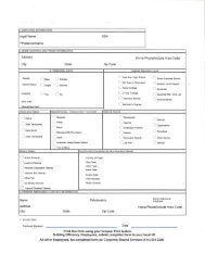
![[PDF] Download our Full Range of Li-Ion Technologies Spec Sheet](https://img.yumpu.com/23687660/1/190x245/pdf-download-our-full-range-of-li-ion-technologies-spec-sheet.jpg?quality=85)

![[PDF] NA Direct & Indirect Supplier Communication Letter - Johnson ...](https://img.yumpu.com/23687657/1/190x245/pdf-na-direct-indirect-supplier-communication-letter-johnson-.jpg?quality=85)


![[PDF] [PDF] - Johnson Controls Inc.](https://img.yumpu.com/23687654/1/190x245/pdf-pdf-johnson-controls-inc.jpg?quality=85)
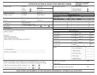


![[PDF] Warren S. Johnson Society of Retirees, Inc.](https://img.yumpu.com/23687624/1/190x245/pdf-warren-s-johnson-society-of-retirees-inc.jpg?quality=85)