Maintenance and Repair Manual - saf-holland
Maintenance and Repair Manual - saf-holland
Maintenance and Repair Manual - saf-holland

You also want an ePaper? Increase the reach of your titles
YUMPU automatically turns print PDFs into web optimized ePapers that Google loves.
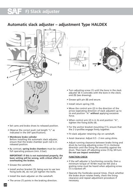
F) Slack adjuster<br />
Automatic slack adjuster – adjustment Type HALDEX<br />
L<br />
10<br />
7<br />
4<br />
1<br />
2<br />
3<br />
2<br />
• Turn adjusting screw (1) until the bore in the slack<br />
adjuster (8.1) coincides with the bore in the clevis<br />
end (9) (see drawing).<br />
• Grease split pin (8) <strong>and</strong> secure.<br />
• Install return spring (10).<br />
• Set cams <strong>and</strong> brake shoes to released position.<br />
• Observe the correct push rod length “L” as<br />
indicated in the SAF specifications.<br />
• Membrane brake cylinder<br />
Before installing the automatic slack adjuster,<br />
ensure that the brake chamber push rod is in<br />
released position.<br />
• By contrast, spring brake chambers must be under<br />
full operating pressure (min. 6 bar).<br />
IMPORTANT: If this is not maintained properly, the<br />
basic setting will be wrong, with critical effect of<br />
overheating the brakes.<br />
• Grease the camshaft.<br />
11<br />
• Install anchor bracket (3), being sure to use two<br />
fixing bolts (4), do not yet tighten the bolts.<br />
• Install the slack adjuster on the camshaft.<br />
• The arrow (7) points in the braking direction.<br />
• Move the control arm (2) in the direction of the<br />
arrow (operating direction of slack adjuster) up to<br />
its end position “A” without applying excessive<br />
force.<br />
• When control arm (2) is in its end position “A”,<br />
tighten the fixing bolts (4).<br />
• For the anchor bracket mounting (11), ensure that<br />
the 2 U-profiles engage firmly together.<br />
• Fit slack adjuster retaining clip on camshaft.<br />
• Axial clearance: Adjust 0.5 - 2 mm using shims.<br />
• Adjust running clearance between brake lining <strong>and</strong><br />
drum by turning adjusting screw (1) in clockwise<br />
direction until the lining fits smoothly against the<br />
drum. Then back off adjusting screw (1) by 3/4 turn.<br />
Do not use impact wrenches!<br />
FUNCTION CHECK<br />
• If the self adjuster is functioning correctly, then a<br />
minimum torque of 18 Nm must be felt <strong>and</strong> a<br />
grating noise must be heard when adjusting screw<br />
(1) is backed off.<br />
• Operate the footbrake several times. Check whether<br />
the brake drum rotates freely, check the lining<br />
clearance <strong>and</strong> repeat adjustment procedure if<br />
necessary.<br />
24