Maintenance and Repair Manual - saf-holland
Maintenance and Repair Manual - saf-holland
Maintenance and Repair Manual - saf-holland

You also want an ePaper? Increase the reach of your titles
YUMPU automatically turns print PDFs into web optimized ePapers that Google loves.
<strong>Maintenance</strong> <strong>and</strong><br />
<strong>Repair</strong> <strong>Manual</strong><br />
SK RS 9042 - SK 1000 ET 0<br />
Edition 01/2006<br />
Service
Vehicle information<br />
Manufacturer...................................................................................................................................<br />
Address.............................................................................................................................................<br />
Body type.........................................................................................................................................<br />
Chassis no.........................................................................................................................................<br />
Year of manufacture ......................................................................................................................<br />
Registration, date-in-service...........................................................................................................<br />
Spare parts service<br />
for SAF axles <strong>and</strong> suspension systems<br />
When ordering spare parts, quote correct<br />
axle identification serial no., refer to the<br />
axle type plate.<br />
Please enter the vehicle identification<br />
figures in the type plates shown below so<br />
that correct specifications are available<br />
when required.<br />
Type plate for axle identification<br />
Identification of axles without type plate<br />
Production No. of axle on right of axle tube as seen in<br />
direction of forward travel.<br />
2
Contents<br />
This manual is intended for the technical workshop personnel responsible for maintenance<br />
<strong>and</strong> repair.<br />
Page<br />
SAF axle identification 2<br />
Notes 4/31<br />
A) Component description 5-6<br />
B) General <strong>saf</strong>ety instructions 7<br />
C) <strong>Maintenance</strong> instructions<br />
<strong>Maintenance</strong> instructions for SAF axles SK RS 9042 – SK 1000 ET 0 8<br />
<strong>Maintenance</strong> schedule for SAF axles SK RS 9042 – SK 1000 ET 0 9<br />
D) Spare part illustration/spare part designation<br />
Spare part illustration <strong>and</strong> spare part designation<br />
for SAF axles SK RS 9042 – SK 1000 ET 0 10-11<br />
E) Installation instructions<br />
<strong>Repair</strong>ing brakes 12-22<br />
F) Slack adjuster<br />
Adjustment of S-cam brake with manual slack adjusters 23<br />
Adjustment of HALDEX automatic slack adjusters 24<br />
Adjustment of S-ABA automatic slack adjusters 25<br />
G) Track control 26-27<br />
H) Service tools 28-29<br />
I) Tightening torque in Nm 30<br />
The item numbers indicated are given only for identification <strong>and</strong> to distinguish between different versions.<br />
Use the part numbers from the valid spare parts documents for identification of spare parts.<br />
SAF axles <strong>and</strong> suspension units are subject to continuous further development; the data <strong>and</strong> drawings<br />
contained in the manual may therefore differ from the details given in the operating permit.<br />
The contents of the manual does not constitute the basis for a legal claim.<br />
Reprinting, reproduction or translation in whole or in part is not permitted.<br />
The issue of this publication invalidates all earlier maintenance <strong>and</strong> repair manuals.<br />
3
4<br />
NOTIZEN / NOTES / NOTE
A) Component Description<br />
The components of the SAF axle Types SK 1000 have important technical details which distinguish them<br />
from other axle types:<br />
– Great ease of installation<br />
(e.g. only 1/4 of the working time is now required for brake repairs)<br />
– Hub unit maintenance free<br />
– Long wheel bearing grease change interval of at least 1,000,000 km<br />
– Favourable lubrication intervals for the camshaft bearing at each brake lining change, but not later<br />
than every 12 months<br />
– Approx. 40 % less individual components in the brakes<br />
– No adjustment of the wheel bearing clearance necessary<br />
Overview of the Components<br />
– Hub cap with snap fit: Removal <strong>and</strong> fitting is quick <strong>and</strong> easy;<br />
simply lever off <strong>and</strong> push on.<br />
– Wheel hub: A compact unit of hub with two equal-sized wheel<br />
bearings <strong>and</strong> seal rings. The wheel bearings are filled with a<br />
longlife grease <strong>and</strong> sealed. The hub unit can only be replaced as<br />
a complete assembly.<br />
– Wheel bearings: Thanks to the protected installation of the<br />
generously dimensioned wheel bearings, service lives of at least<br />
1,000,000 km <strong>and</strong> more can be achieved. Grease changing at<br />
brake repairs is no longer necessary.<br />
After 1,000,000 km, check the wheel bearing clearance <strong>and</strong><br />
replace the hub unit, if necessary.<br />
5
A) Component Description<br />
Wheel bearing clearance<br />
Thanks to the precision manufacturing of the components, no<br />
adjustment of wheel bearing clearance is necessary.<br />
The correct position of the wheel bearing is achieved simply by<br />
tightening the axle nut.<br />
Axle nuts<br />
Right-h<strong>and</strong> side – right-h<strong>and</strong> thread<br />
Left-h<strong>and</strong> side – left-h<strong>and</strong> thread<br />
Additional locking of the axle nuts is therefore not necessary.<br />
Brake shoes<br />
The brake shoes are each supported spherically on a ball <strong>and</strong> are<br />
held by a spring clamp. Only one return spring is required for the<br />
return of the brake shoes. The brake shoe cam rollers are guided<br />
exactly in the specially machined S-cam profile.<br />
Brake linings<br />
Two different asymmetrically formed lining segments are riveted<br />
onto the brake shoes. The thicker end of the lining is installed on<br />
the S-cam side (cam roller).<br />
As a result of this scythe-shaped brake lining contour, uniform maximum<br />
wear of the brake lining over the whole surface is achieved<br />
during normal operation.<br />
The brake linings have a groove cut into the edge by laser which<br />
marks the maximum permissible lining wear.<br />
Camshaft<br />
Until 02/98 the following applied:<br />
The camshaft bearings are brass bushes situated in the brake calliper.<br />
The bearing bush in the rod guide is made from PVC.<br />
From 03/98 the following applies:<br />
The camshaft bearings in the brake calliper as well as the rod guide<br />
are in the form of a screwed compact bearing, that guarantees a<br />
quick replacement. Both bearing are provided with grease nipples<br />
<strong>and</strong> must be greased every 12 months.<br />
For both variations the following applies:<br />
Both bearings have a long-life lubrication <strong>and</strong> are protected by seal<br />
rings <strong>and</strong> rubber sleeves against the ingress of dirt <strong>and</strong> splash water.<br />
On the slack adjuster end the camshaft has a milled groove <strong>and</strong> a<br />
slip-on indicator for visual checking of the brake lining wear.<br />
When the wear indicators have reached a horizontal position, an<br />
inspection of the brake lining thickness must be carried out.<br />
Inspection of the brake lining thickness<br />
During maintenance work, the thickness of the brake linings can be<br />
inspected at two sight holes in the rear cover plate.<br />
6
B) General <strong>saf</strong>ety instructions<br />
Please observe the following <strong>saf</strong>ety instructions in order to maintain the operational <strong>and</strong> road <strong>saf</strong>ety<br />
of your SAF axles <strong>and</strong> suspension systems:<br />
1. The wheel contact surfaces between the wheel disc <strong>and</strong> wheel hub <strong>and</strong> the wheel nut contact surface<br />
at the wheel disc must not be additionally painted. The contact surfaces must be clean, smooth<br />
<strong>and</strong> free from grease. Failure to observe this may result in the wheel coming loose. Any additional<br />
instructions of the wheel manufacturer must also be observed.<br />
2. Only the wheel <strong>and</strong> tyre sizes approved by the trailer builder may be used. The tyres must always have<br />
the specified inflation pressure.<br />
3. The brake systems of the tractor <strong>and</strong> the trailer/semi-trailer must be synchronised by means of a<br />
tractor/trailer brake synchronisation not later than 5,000 km after the initial start of operation of the<br />
trailer/semi-trailer in order to ensure a <strong>saf</strong>e <strong>and</strong> uniform braking behaviour <strong>and</strong> uniform brake pad<br />
wear. Tractor/trailer brake synchronisations should be carried out by appropriately qualified <strong>and</strong><br />
equipped brake workshops.<br />
The use of an additional braking system, such as a trailer anti-jackknife brake is forbidden by law on<br />
vehicles with type approval after January 1999.<br />
4. Before starting a journey, ensure that the maximum permissible axle load is not exceeded <strong>and</strong> that the<br />
load is distributed equally <strong>and</strong> uniformly.<br />
5. On trailers with air suspension, ensure that the air bags are completely filled with air before starting<br />
the journey. Incompletely filled air bags may result in damage to axles, suspension, frame <strong>and</strong><br />
superstructure <strong>and</strong> impair road <strong>saf</strong>ety.<br />
6. Ensure that the brakes are not overheated by continuous operation.<br />
With drum brakes, overheating can result in a hazardous deterioration in the braking efficiency.<br />
With disc brakes, overheating can result in damage to surrounding components – in particular the<br />
wheel bearings. This can result in a significant deterioration in road <strong>saf</strong>ety, e.g. failure of wheel<br />
bearings.<br />
7. The parking brake must not be immediately applied when the brakes are hot, as the brake discs <strong>and</strong><br />
brake drums may be damaged by different stress fields during cooling.<br />
8. Use the supports provided when loading <strong>and</strong> unloading in order to avoid damage to the axle.<br />
9. Observe the operating recommendation of the trailer builder for off-road operation of the installed<br />
axles <strong>and</strong> suspension systems.<br />
The SAF definition of OFF-ROAD means driving on non-asphalted / non-concreted routes, such as e.g.<br />
gravel roads, agricultural <strong>and</strong> forestry tracks, on construction sites <strong>and</strong> in gravel pits.<br />
Off-road operation of SAF axles <strong>and</strong> suspension systems not designed for the purpose may result in<br />
damage <strong>and</strong> hence to an impairment of road <strong>saf</strong>ety.<br />
10. SAF axles <strong>and</strong> suspension systems require continuous care, service <strong>and</strong> maintenance in order to<br />
maintain operational <strong>and</strong> road <strong>saf</strong>ety <strong>and</strong> to be able to recognise natural wear <strong>and</strong> defects in good<br />
time.<br />
The daily inspection of the trailer for road <strong>saf</strong>ety before starting the journey is one of the driver’s<br />
obligations.<br />
SAF recommends that at least the inspections <strong>and</strong> maintenance operations described on page 6 should<br />
be carried out.<br />
We recommend the use of original SAF spare parts.<br />
A close-knit service network of SAF partner companies is available for the technical support of the SAF axle<br />
<strong>and</strong> suspension systems <strong>and</strong> for the supply of original SAF spare parts (see rear cover or on the Internet<br />
under www.<strong>saf</strong>-axles.com).<br />
Updates will be published as necessary on the Internet under www.<strong>saf</strong>-axles.com.<br />
7
C) <strong>Maintenance</strong> instructions<br />
SK 1000 Drum / ET 0<br />
SK RS 9042 - SK 1000 ET 0<br />
<strong>Maintenance</strong> intervals<br />
whichever comes first<br />
Mechanical check<br />
Mileage intervals ><br />
Time intervals ><br />
After first<br />
5,000 km<br />
or<br />
After first<br />
month<br />
every<br />
30,000 km<br />
every<br />
3 months<br />
Periodic checks<br />
every<br />
75,000 km<br />
every<br />
6 months<br />
every<br />
150,000 km<br />
every<br />
12 months<br />
Note: Be sure to retighten wheel nuts to the prescribed torque<br />
after the first 50 km <strong>and</strong> 150 km (<strong>and</strong> after every wheel removal).<br />
Check <strong>and</strong> adjust hub end-float (if required) after every brake<br />
lining replacement.<br />
Pack wheel bearings with fresh grease after 500,000 km or<br />
60 months, whichever comes first.<br />
Lubricate camshaft bearings after every brake lining replacement,<br />
however, at least every 12 months.<br />
The U-bolt must be tightened once only within the first 5,000 km<br />
after the first loaded test-drive.<br />
•<br />
• •<br />
Visual <strong>and</strong> <strong>saf</strong>ety inspection<br />
– Perform general annual inspection<br />
(brakes, air bags, tyres, etc.)<br />
– Perform general annual <strong>saf</strong>ety check<br />
(tractor/ (semi-) trailer brake compatibility, ABS etc.)<br />
Special service conditions<br />
Vehicles with long st<strong>and</strong>ing periods:<br />
Vehicles used under extreme conditions:<br />
service at specified time intervals<br />
service at suitably reduced intervals<br />
Warranty claims will only be accepted as long as the operating <strong>and</strong> maintenance instructions have been<br />
complied with <strong>and</strong> if SAF approved spare parts have been fitted.<br />
8
C) <strong>Maintenance</strong> instructions<br />
SK 1000 Drum / ET 0<br />
SK RS 9042 - SK 1000 ET 0<br />
Hub unit<br />
Hub unit maintenance-free.<br />
Inspect for signs of wear at each brake lining change<br />
(e.g. escape of grease).<br />
After brake relining, lubricate camshaft bearings<br />
whilst rotating the camshaft through 360° several<br />
times.<br />
Do not disassemble the wheel bearing assembly.<br />
Use a vacuum cleaner to remove brake dust.<br />
High-pressure cleaners <strong>and</strong> liquid cleaners must not<br />
be used on the brake drum or hub unit. Remove<br />
residues of grease from the stub shaft <strong>and</strong> apply<br />
SAF fitting paste.<br />
Lubricant specification:<br />
Camshaft:<br />
SAF Part No. 4 387 0011 05<br />
Stub axle:<br />
SAF Part No. 4 387 0015 06<br />
SAF fitting paste<br />
Brake anchor bracket ball:<br />
SAF Part No. 4 387 0007 00<br />
copper paste<br />
Hub nut tightening<br />
LH direction of travel - LH thread.<br />
RH direction of travel - RH thread.<br />
Tightening torque 900 Nm. Each hub unit must<br />
be rotated smoothly at least twice while tightening<br />
the bolts.<br />
Hub nuts with LH threads are marked with<br />
a groove milled into the hex outside.<br />
BRAKE type SNK 420<br />
Max. permissible turned brake drum bore:<br />
424.0 mm<br />
Brake drum bore with max. permissible wear:<br />
425.0 mm<br />
SAF approved brake linings: BERAL 1541, BREMSKERL 6386<br />
Turn new brake linings to brake drum bore dimension + 0.3 mm.<br />
When renewing rivets, observe the manufacturer’s instructions regarding the brake lining form<br />
(see leaflet enclosed in pack); rivet on the brake linings with the thicker lining on the cam roller side.<br />
d 0<br />
nominal Normalmaß size<br />
420.0<br />
d 1<br />
1st 1. oversize Rep.-Stufe<br />
422.0<br />
d 2<br />
2nd 2. Rep.-Stufe oversize<br />
424.0<br />
Brake<br />
size<br />
SAF parts no.<br />
brake lining<br />
Brake drum / brake lining<br />
refacing stages in mm<br />
Brake linings<br />
Rivets<br />
DIN 7338<br />
rivet<br />
Nominal size 1st oversize 2nd oversize<br />
number per axle<br />
SNK 420 d 0 -420.0 d 1 -422.0 d 2 -424.0<br />
x 180 1 057 0060 00 20.6 21.6 22.6<br />
1 057 0061 00 20.0 21.0 22.0<br />
x 200 1 057 0066 00 20.6 21.6 22.6<br />
1 057 0067 00 20.0 21.0 22.0<br />
4 64 B 8 x 15<br />
Assembly tools<br />
SAF parts no.<br />
Lever for hub cap 1 434 1041 00<br />
Hub nut spanner 1 012 0024 00<br />
Puller 4 434 3822 00<br />
Brake shoe clamping device 3 349 1001 00<br />
Brake drum fixing flanges 3 434 1040 01<br />
9
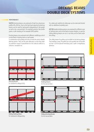
D) Spare part illustrations<br />
SK 1000 Drum / ET 0<br />
SK RS 9042 - SK 1000 ET 0<br />
Torque wrench settings<br />
Use a torque wrench.<br />
The use of impact wrenches<br />
is not accepted.<br />
Wheel nuts:<br />
Spigot-hub-centred fixing:<br />
M 22 x 1.5 / 600 Nm<br />
Bolt-centred fixing:<br />
M 22 x 1.5 / 430 Nm<br />
U-bolts:<br />
(diagonally in three stages)<br />
M 22 / 650 Nm<br />
Shock absorber:<br />
M 24 / 400 Nm<br />
93<br />
091 96<br />
97<br />
98<br />
94<br />
92<br />
29<br />
30<br />
31<br />
40<br />
40.1<br />
39<br />
34<br />
95<br />
41<br />
94<br />
89.1<br />
99<br />
90<br />
27<br />
64<br />
70<br />
73 72<br />
75 66 65 71<br />
74<br />
86<br />
85.1<br />
081/082<br />
88.1<br />
88<br />
87<br />
18<br />
15<br />
010<br />
12<br />
18.3<br />
18<br />
89.2<br />
89.3<br />
059<br />
4.1<br />
6.2 6 6.1<br />
3<br />
25<br />
Typenschild plate<br />
78<br />
4<br />
5<br />
01<br />
20<br />
76.2 76 22/22.1<br />
19<br />
10
D) Spare part designation<br />
SK 1000 Drum / ET 0<br />
SK RS 9042 - SK 1000 ET 0<br />
Item Parts designation Item Parts designation<br />
01 Axle beam assembly<br />
including items 3 - 25<br />
3 Spherical mounting plate<br />
4 Protective plug for ABS<br />
4.1 Protective plug in axle tube<br />
5 Ball<br />
6 Camshaft bearing,<br />
brake carrier side<br />
6.1 Riffle bolt<br />
6.2 Lock nut M 8<br />
010 Camshaft bearing assembly<br />
linkage adjustment side<br />
including items 12, 15, 18<br />
12 Compact bearing,<br />
linkage adjuster side<br />
15 Pinch bolt M 8 x 22<br />
18 Bellows<br />
18.3 Brake lining wear gauge<br />
19 O-ring<br />
20 O-ring<br />
22 Hub nut, RH thread W.A.F. 140<br />
22.1 Hub nut, LH thread W.A.F. 140<br />
24 Lock nut<br />
25 Mounting plate for MB cylinder<br />
27 Hub unit<br />
29 Brake drum<br />
30 Wheel bolt assembly<br />
including items 31 - 34<br />
31 Riffle bolt<br />
34 Wheel nut with pressure plate<br />
39 O-ring<br />
40 Hub cap assembly<br />
including items 39, 41<br />
40.1 Wheel cap assembly with exciter<br />
41 Plug<br />
059 Brake assembly<br />
including items 64, 74 - 75<br />
70 Brake lining set<br />
including items 71, 72, 73<br />
71 Brake lining, cam roller side<br />
72 Brake lining, ball side<br />
73 Rivet<br />
74 Clamp<br />
75 Return spring<br />
76 ABS sensor bracket<br />
76.1 Hex bolt<br />
78 ABS sensor<br />
081 Camshaft assembly (LH)<br />
including items 18.3, 85.1 - 88.1<br />
082 Camshaft assembly (RH)<br />
including items 18.3, 85.1 - 88.1<br />
85.1 Disc spring<br />
86 Clamp<br />
87 Washer<br />
88 Washer<br />
88.1 Clamp<br />
with automatic adjustment<br />
89.1 Automatic slack adjuster<br />
89.2 Anchor plate, RH<br />
89.3 Anchor plate, LH<br />
90 Return spring<br />
091 Dust cover assembly<br />
including items 92 - 99<br />
92 Dust cover, RH<br />
93 Dust cover, LH<br />
94 Plug<br />
95 Cable clamp<br />
96 Hex bolt<br />
97 Clamp<br />
98 Plug<br />
99 Rubber grommet, ABS<br />
64 Brake shoe assembly<br />
including items 65, 71 - 73<br />
65 Brake shoe with item 66<br />
66 Cam roller<br />
When ordering spare parts quote correct axle identification serial no., refer to the axle type plate.<br />
11
E) Installation instructions<br />
<strong>Repair</strong>ing the brakes<br />
Removing <strong>and</strong> installing the wheel hub<br />
Park the vehicle on level, solid ground <strong>and</strong> chock the wheels to<br />
prevent the vehicle from rolling away.<br />
Lift the axle using a jack.<br />
Completely release the wheel brake by turning the adjusting screw<br />
on the slack adjuster until cam <strong>and</strong> brake shoes are in the end<br />
position.<br />
Prise the wheel cap off the hub unit using a crowbar SAF Part No.<br />
1 434 1041 00 inserted into one of the grooves around the collar of<br />
the wheel cap.<br />
Press the ABS sensor completely out of the sensor mounting block<br />
<strong>and</strong> place inside the axle tube.<br />
The sensor holder can remain on the axle nut.<br />
Loosen the axle nut <strong>and</strong> unscrew from the stub axle.<br />
Axle nut wrench: SAF Part No. 1 012 0024 00.<br />
Note:<br />
Axle nut: W.A.F. 140<br />
On left-h<strong>and</strong> side of vehicle (as seen in direction of forward travel)<br />
– left-h<strong>and</strong> thread<br />
Identification of axle nut with left-h<strong>and</strong> thread:<br />
Milled groove on outside of hexagonal head.<br />
Place a wheel mounting trolley under the hub unit <strong>and</strong> pull the<br />
complete hub unit with wheel from the stub axle.<br />
12
E) Installation instructions<br />
The complete hub unit with wheel can be easily pulled from<br />
the stub shaft.<br />
If the bearing inner races tilt on the stub shaft, the hub unit<br />
can be pulled off using a normal workshop puller or<br />
SAF Part No. 4 434 3822 00.<br />
Note:<br />
Do not dismantle the hub unit!<br />
The hub unit is maintenance free. However, a visual inspection for<br />
wear should be carried out (e.g. escape of grease).<br />
Brake drum cleaning:<br />
The brake drum may only be cleaned using a dry cleaning material.<br />
Liquid cleansers, high-pressure cleaners or machine cleaning are not<br />
permitted. With this type of cleaning, there is a danger of cleaning<br />
fluid entering the hub unit <strong>and</strong> resulting in faults in the wheel<br />
bearing lubrication system.<br />
Disassembling the brakes<br />
Lever the spring clip out of the retainer in the brake shoe using a<br />
screwdriver.<br />
Remove the spring clip.<br />
Pull the upper brake shoe sideways over the cam <strong>and</strong> ball pivot<br />
point <strong>and</strong> then remove both brake shoes from the brake carrier.<br />
Inspecting the camshaft<br />
Push the camshaft backwards <strong>and</strong> forwards firmly in the compact<br />
bearing <strong>and</strong> measure the radial clearance.<br />
Max. permissible radial clearance: 2.0 mm.<br />
If the maximum permissible radial clearance is exceeded, the<br />
camshaft must be removed <strong>and</strong> the compact bearing on the brake<br />
carrier must be replaced.<br />
‰<br />
13
E) Installation instructions<br />
Camshaft bearing arrangement<br />
Removing <strong>and</strong> installing the camshaft<br />
Removing the slack adjuster.<br />
Remove the spring clip from<br />
the groove in the camshaft<br />
<strong>and</strong> pull the camshaft completely<br />
out of the bearing.<br />
Arrangement <strong>and</strong> installation<br />
position of the camshaft bearings,<br />
see drawing above.<br />
Remove the bolts from the compact bearing <strong>and</strong> replace with a new<br />
bearings (see page 10, item 81 with parts 85.1 - 88.1 <strong>and</strong> item 10<br />
with parts 12, 15 <strong>and</strong> 18).<br />
After installation of the new<br />
compact bearing, the camshaft<br />
must rotate freely. Insert<br />
the bolts <strong>and</strong> fit the nuts.<br />
14
E) Installation instructions<br />
Tightening torque for the bolts on the compact bearing:<br />
- Brake side 40 Nm<br />
- Slack adjuster side 35 Nm<br />
Replace the complete compact bearing assembly on the slack<br />
adjuster.<br />
Coat the splines on the camshaft <strong>and</strong> the splines on the slack<br />
adjuster with copper paste.<br />
Suitable greases, see chapter “<strong>Maintenance</strong> instructions”!<br />
Push washer <strong>and</strong> new sealing<br />
sleeve onto the camshaft.<br />
Insert the canshaft into the<br />
bearings <strong>and</strong> secure in position<br />
with the circlip.<br />
Align the compact bearings with the camshaft, tighten the mounting<br />
bolts <strong>and</strong> check the camshaft for free rotation.<br />
If necessary, correct the position of the compact bearing relative to<br />
the slack adjuster again.<br />
Push on both seal sleeves until they contact the compact bearing on<br />
the slack adjuster side.<br />
15
E) Installation instructions<br />
Install the slack adjuster <strong>and</strong> wear indicator; fit both cover plates<br />
<strong>and</strong> secure to the axle body with clamps.<br />
Grease the camshaft bearing in the brake carrier <strong>and</strong> in the plastic<br />
bearing bush using a grease gun until grease emerges at the end of<br />
the bearing.<br />
Turn the camshaft through 360º several times.<br />
Check that the bearing is completely lubricated <strong>and</strong> that the camshaft<br />
turns easily.<br />
Lubrication intervals for the camshaft bearing, see chapter<br />
“<strong>Maintenance</strong> instructions”.<br />
Brake linings<br />
Original dimensions <strong>and</strong> wear limits, see table in chapter<br />
“<strong>Maintenance</strong> instructions”.<br />
Two different brake linings are riveted onto each brake shoe.<br />
The lining contour tapers towards the ball side.<br />
The thicker end of the brake lining is riveted on the roller side<br />
(S-cam).<br />
Corrosion-proofed steel rivets are used for securing the linings.<br />
The brake linings have a monitoring shoulder on the face end<br />
indicating the brake lining type approved by SAF <strong>and</strong> the wear<br />
limit for the minimum brake lining thickness.<br />
Only brake linings of the same quality may be installed on the<br />
same axle.<br />
Observe the approved rivet quality.<br />
Replacement of the brake lining<br />
Clean all parts <strong>and</strong> inspect for wear. Inspect the brake drum for<br />
wear <strong>and</strong> turn down to the next repair stage, if necessary (see table<br />
in chapter “<strong>Maintenance</strong> instructions”).<br />
Remove the brake lining from the brake shoe.<br />
Thoroughly clean the mounting surface for the brake lining on the<br />
brake shoe; grind slightly, if necessary.<br />
Carefully remove any corrosion from the lining plate. Protect the<br />
contact surface against corrosion with a thin coating of zinc dust<br />
primer.<br />
Replace the brake linings according to the repair stage of the brake<br />
drum (see table in chapter “<strong>Maintenance</strong> instructions”).<br />
Observe the position of the different brake lining segments.<br />
The thicker end of the brake lining is riveted on the roller side<br />
(S-cam).<br />
16
E) Installation instructions<br />
The brake lining must contact the brake drum over its full surface.<br />
The corners of the brake lining must not be broken <strong>and</strong> the lining<br />
must not be cracked at the rivets.<br />
Required riveting force: 25,000 N<br />
Read off the required working pressure on the setting plate of the<br />
riveter <strong>and</strong> set the pressure at the pressure gauge.<br />
Observe the riveting sequence 1 - 8 for each brake lining half.<br />
Brake drum<br />
Brake drum diameter<br />
Permissible wear limits, see table in chapter<br />
“<strong>Maintenance</strong> instructions”.<br />
Brake drum cleaning:<br />
The brake drum may only be cleaned using a dry cleaning material.<br />
Liquid cleansers, high-pressure cleaners or machine cleaning are not<br />
permitted. With this type of cleaning, there is a danger of cleaning<br />
fluid entering the hub unit <strong>and</strong> resulting in faults in the wheel<br />
bearing lubrication system.<br />
Inspecting the brake drum<br />
Removing <strong>and</strong> installing the brake drum<br />
Inspect the brake surface of the brake drum closely for further<br />
serviceability.<br />
Brake drums with fine hairline cracks in the contact surface can<br />
continue to be used. If the contact surfaces of the brake drums<br />
exhibit deep scoring, the drums must be turned down. If cracks<br />
are still visible after turning down, replace the brake drums.<br />
Measure the brake drum diameter <strong>and</strong> turn down to the next<br />
repair stage, if necessary. When the maximum permissible brake<br />
drum inside diameter is reached, the brake drums must be replaced.<br />
Permissible wear limits, see table in chapter<br />
“<strong>Maintenance</strong> instructions”.<br />
17
E) Installation instructions<br />
Note:<br />
Do not dismantle the hub unit for turning out the brake drum.<br />
Centrehub unit on the brake drum lathe using clamping device,<br />
SAF Part No. 3 343 1040 01.<br />
Further machining of the brake drum can then be carried out as<br />
normal in the workshop.<br />
Replacing the brake drum<br />
For dismantling of the brake drum, drive all wheel bolts out of the<br />
wheel hub using a hammer. Removal of the snap rings (33) is not<br />
necessary. Before assembly of the hub unit <strong>and</strong> brake drum, remove<br />
any corrosion from the contact surfaces.<br />
Drive the wheel studs into the brake drum flange until they are<br />
flush with the inner surface using a normal workshop drift.<br />
Ensure that the twist lock engages correctly.<br />
The circlips (33) are no longer required.<br />
If necessary, the wheel studs can also be correctly positioned by<br />
pulling in using a wheel nut.<br />
Installing the brake shoes<br />
Check the proper mounting seat of the two balls in the brake carrier.<br />
The balls can still be moved easily by h<strong>and</strong> in their mountings.<br />
If a ball has come loose in its mounting, a secure fit can be achieved<br />
again by tapping the sides of the mounting lightly with a hammer.<br />
18
E) Installation instructions<br />
Check the proper mounting of the cam roller on the brake shoes.<br />
The cam roller must not jam in the mounting. It must turn easily, but<br />
without radial clearance.<br />
Replace the cam roller if the journal is severely worn.<br />
When installing new cam rollers, a secure mounting in the brake<br />
shoe can be achieved by pressing in the two side faces in a vice.<br />
Apply copper paste to the brake shoes, to the ball surface <strong>and</strong> to<br />
the two journals of the cam roller.<br />
See chapter “<strong>Maintenance</strong> instructions” for recommended media.<br />
Apply copper paste to the<br />
two balls in the brake carrier.<br />
See chapter<br />
“<strong>Maintenance</strong> instructions”<br />
for recommended media.<br />
Hook a new return spring into the tabs of the brake shoes.<br />
Position the upper brake shoe on the ball pivot point <strong>and</strong> the cam<br />
roller surface.<br />
Tilt the lower brake shoe towards the cover plate until the correct<br />
seating on the cam <strong>and</strong> on the ball pivot point is achieved; if<br />
necessary, turn the camshaft into the required position. Insert the<br />
spring clip into the groove on the lower brake shoe <strong>and</strong> hook into<br />
the retainer on the upper brake shoe using a screwdriver.<br />
Ensure that the spring clip is fitted securely.<br />
Check the assembly <strong>and</strong> the proper operational condition of the<br />
installed brakes.<br />
Turn the camshaft by actuating the slack adjuster by h<strong>and</strong> <strong>and</strong> check<br />
the correct positioning <strong>and</strong> smooth return of the brake shoes;<br />
readjust the camshaft bearing, if necessary.<br />
19
E) Installation instructions<br />
Turning down the brake linings<br />
Even after a brake lining replacement with new brake linings, the<br />
brake lining must be in full contact with the braking surface of the<br />
brake drum over its whole surface in order to achieve an optimum<br />
braking effect.<br />
For a uniform contact pattern, the brake lining must therefore be<br />
turned down centrally to the stub shaft on a normal workshop<br />
brake lining lathe.<br />
Set the lathe tool to the diameter of the brake drum + 0.3 mm.<br />
Use the clamping device for the brake shoes,<br />
SAF Part No. 3 349 1001 00.<br />
Leave the clamping device loose at this stage – do not clamp!<br />
Turn the camshaft by actuating the slack adjuster until the brake<br />
shoes are spread sufficiently that the lathe tool can take off material<br />
over the whole circumference of the brake linings.<br />
Now tighten the clamping device.<br />
Turn down the brake linings.<br />
Inspect the brake lining surface all over for complete machining. If<br />
necessary, loosen the clamping device <strong>and</strong> spread the brake shoes<br />
slightly further <strong>and</strong> repeat the machining process.<br />
Remove all chips of the brake lining from the brake shoes <strong>and</strong> stub<br />
axle.<br />
Brake lining lathe<br />
120 mm diameter supporting tube for axle type SK 9042 / 11242<br />
Order adapter sleeves from the lathe manufacturer.<br />
Installing the wheel hub with brake drum<br />
Coat the wheel bearing seating surfaces on the stub shaft<br />
<strong>and</strong> in the wheel hub all round with SAF fitting paste<br />
(SAF Part No. 4 387 0015 06).<br />
See chapter “<strong>Maintenance</strong> instructions” for recommended media.<br />
20
E) Installation instructions<br />
Completely release the wheel brake by turning the adjusting screw<br />
on the slack adjuster until the cam rollers of the brake shoes are in<br />
the end position.<br />
Position a wheel mounting carriage <strong>and</strong> push the complete wheel<br />
hub unit with brake drum onto the stub axle.<br />
Inspect the O-rings (19) on the axle nut <strong>and</strong> replace, if necessary.<br />
Screw on the axle nut.<br />
Axle nut: W.A.F. 140<br />
On left-h<strong>and</strong> side of vehicle (as seen in direction of forward travel)<br />
– left-h<strong>and</strong> thread<br />
Identification of axle nut with left-h<strong>and</strong> thread: Milled groove on<br />
outside of hexagonal head.<br />
Tighten the axle nut.<br />
Axle nut wrench: SAF Part No. 1 012 0024 00<br />
Tightening torque 900 Nm. Each hub unit must<br />
be rotated smoothly at least twice while tightening the bolts.<br />
Special locking of the axle nut is not necessary.<br />
Completely coat the ABS sensor with copper paste <strong>and</strong> install in the<br />
sensor holder.<br />
On the wheel hub, replace the O-ring (39) for the snap fastener of<br />
the wheel cap. Push on the hub cap <strong>and</strong> check that it is securely<br />
seated.<br />
Remove the plug from the hub cap <strong>and</strong> adjust the ABS sensor until<br />
it is just contacting the exciter ring.<br />
Insert the plug into the hub cap again.<br />
Measure the voltage output on the ABS sensor cable using a<br />
voltmeter (approx. 100 mV) whilst turning the brake drum.<br />
Check the sensor, if necessary.<br />
Check that the cover plate of the brake shoes is correctly installed<br />
<strong>and</strong> correct the positioning, if necessary, using a clamp.<br />
21
E) Installation instructions<br />
Checking the brake lining thickness<br />
Checking the brake lining thickness<br />
The brake lining thickness can be checked at the two sight holes in<br />
the rear cover plate.<br />
Carry out the adjustment of the wheel brakes as normal at the slack<br />
adjuster.<br />
See chapter “Slack adjuster”.<br />
Carry out a normal test run <strong>and</strong> check the function <strong>and</strong> adjustment<br />
of the wheel brakes.<br />
Check the freewheeling of the brake drum <strong>and</strong> check the clearance;<br />
repeat the adjustment at the slack adjuster, if necessary.<br />
Brake lining wear indicator<br />
On the slack adjuster the camshaft has a milled groove <strong>and</strong> a slip-on<br />
indicator for visual checking of the brake lining wear.<br />
Wear indicator in vertical position = Brake linings as good as new<br />
When the wear indicators have reached a horizontal position, an<br />
inspection of the brake lining thickness must be carried out.<br />
22
F) Slack adjuster<br />
Braking system - checking <strong>and</strong> adjustment<br />
S-cam brakes with manual slack adjusters<br />
Due to normal brake drum <strong>and</strong> brake lining wear, the wheel brakes must be regularly adjusted in order to<br />
maintain the full brake cylinder stroke. To ensure maximum brake efficiency, the clearance between brake<br />
lining <strong>and</strong> drum must be kept to an absolute minimum. To determine this clearance, check the brake cylinder<br />
stroke while full pressure is applied to the service brake. If the path at the yoke end measures more than 2/3<br />
of the maximum cylinder stroke then the brake must be adjusted without delay. With a correctly adjusted<br />
brake, it should be impossible to move the piston rod by h<strong>and</strong> more than 15 mm.<br />
Turn adjusting screw to the<br />
right until...<br />
... the brake shoes fit<br />
closely to the brake drum.<br />
No-load – absolutely<br />
no play is permissible<br />
between the piston<br />
<strong>and</strong> membrane.<br />
Turn adjusting screw to the<br />
left, until ...<br />
...the no-load stroke at the<br />
slack adjuster (at 127 mm) is<br />
approx. 10 - 15 mm long.<br />
Adjusting screw<br />
(width across flats 19 mm)<br />
The wheel must rotate freely<br />
with no grating noise.<br />
Special instructions for automatic slack adjusters are given on the following pages.<br />
A = At 1/2 stroke, the angle must not exceed 90°.<br />
B = On full brake application, the slack adjuster <strong>and</strong> axle beam must not come in<br />
contact with each other.<br />
L = Inspect piston rod according to technical specification.<br />
23
F) Slack adjuster<br />
Automatic slack adjuster – adjustment Type HALDEX<br />
L<br />
10<br />
7<br />
4<br />
1<br />
2<br />
3<br />
2<br />
• Turn adjusting screw (1) until the bore in the slack<br />
adjuster (8.1) coincides with the bore in the clevis<br />
end (9) (see drawing).<br />
• Grease split pin (8) <strong>and</strong> secure.<br />
• Install return spring (10).<br />
• Set cams <strong>and</strong> brake shoes to released position.<br />
• Observe the correct push rod length “L” as<br />
indicated in the SAF specifications.<br />
• Membrane brake cylinder<br />
Before installing the automatic slack adjuster,<br />
ensure that the brake chamber push rod is in<br />
released position.<br />
• By contrast, spring brake chambers must be under<br />
full operating pressure (min. 6 bar).<br />
IMPORTANT: If this is not maintained properly, the<br />
basic setting will be wrong, with critical effect of<br />
overheating the brakes.<br />
• Grease the camshaft.<br />
11<br />
• Install anchor bracket (3), being sure to use two<br />
fixing bolts (4), do not yet tighten the bolts.<br />
• Install the slack adjuster on the camshaft.<br />
• The arrow (7) points in the braking direction.<br />
• Move the control arm (2) in the direction of the<br />
arrow (operating direction of slack adjuster) up to<br />
its end position “A” without applying excessive<br />
force.<br />
• When control arm (2) is in its end position “A”,<br />
tighten the fixing bolts (4).<br />
• For the anchor bracket mounting (11), ensure that<br />
the 2 U-profiles engage firmly together.<br />
• Fit slack adjuster retaining clip on camshaft.<br />
• Axial clearance: Adjust 0.5 - 2 mm using shims.<br />
• Adjust running clearance between brake lining <strong>and</strong><br />
drum by turning adjusting screw (1) in clockwise<br />
direction until the lining fits smoothly against the<br />
drum. Then back off adjusting screw (1) by 3/4 turn.<br />
Do not use impact wrenches!<br />
FUNCTION CHECK<br />
• If the self adjuster is functioning correctly, then a<br />
minimum torque of 18 Nm must be felt <strong>and</strong> a<br />
grating noise must be heard when adjusting screw<br />
(1) is backed off.<br />
• Operate the footbrake several times. Check whether<br />
the brake drum rotates freely, check the lining<br />
clearance <strong>and</strong> repeat adjustment procedure if<br />
necessary.<br />
24
F) Slack adjuster<br />
Automatic slack adjuster - adjustment Type S-ABA<br />
L<br />
10<br />
2<br />
7<br />
4<br />
1<br />
2<br />
3<br />
• Set cams <strong>and</strong> brake shoes to released position.<br />
• Observe the correct push rod length “L” as<br />
indicated in the SAF specifications.<br />
• Possible adjustment range for control lever<br />
position (slack adjuster) up to its end position<br />
without applying excessive force.<br />
• Membrane brake cylinder<br />
Before installing the automatic slack adjuster,<br />
ensure that the brake chamber push rod is in<br />
released position.<br />
• By contrast, spring brake chambers must be under<br />
full operating pressure (min. 6 bar).<br />
IMPORTANT: If this is not maintained properly, the<br />
basic setting will be wrong, with critical effect of<br />
overheating the brakes.<br />
• Grease the camshaft.<br />
• Install anchor bracket (3), being sure to use two<br />
fixing bolts (4), do not yet tighten the bolts.<br />
• Install the slack adjuster on the camshaft.<br />
• The arrow (7) points in the braking direction.<br />
• Turn adjusting screw (1) until the bore in the slack<br />
adjuster (8.1) coincides with the bore in the clevis<br />
end (9) (see drawing).<br />
• For the fixed point mounting, ensure that the<br />
2 U-profiles engage firmly inside one another.<br />
• Grease split pin (8) <strong>and</strong> secure.<br />
• Install return spring (10).<br />
• Mount slack adjuster on camshaft.<br />
• Axial clearance: Adjust 0.5 - 2 mm using shims.<br />
• Adjust control arm.<br />
• Adjust running clearance between brake lining <strong>and</strong><br />
drum by turning adjusting screw (1) in clockwise<br />
direction until the lining fits smoothly against the<br />
drum. Then back off adjusting screw (1) by 3/4 turn.<br />
Do not use impact wrenches!<br />
FUNCTION CHECK<br />
• If the self adjuster is functioning correctly, then a<br />
minimum torque of 18 Nm must be felt <strong>and</strong> a<br />
grating noise must be heard when adjusting screw<br />
(1) is backed off.<br />
• Operate the footbrake several times. Check whether<br />
the brake drum rotates freely, check the lining<br />
clearance <strong>and</strong> repeat adjustment procedure if<br />
necessary.<br />
25
G) Track control<br />
Commercially available optical measuring instruments must be used<br />
for performance of the track control on SAF SK Series axles.<br />
1) For the original installation in the vehicle manufacturer's works<br />
using universal centering on the wheel studs.<br />
2) For the service inspection using universal rim centering.<br />
26
G) Track control<br />
For track control, the air suspension ride height must be adjusted to the values specified<br />
by SAF.<br />
Semi-trailers with trailing steering axle<br />
Distance A, B, C, max. permissible deviation 1.0 mm<br />
Toe setting + 3.0 mm/m<br />
Camber + 3.0 mm/m<br />
In the case of trailing steering axles the membrane cylinder must be pressurised to 2.0 bar.<br />
Total toe 4.0 mm/m i.e. 2.0 mm/m per wheel side (values apply to unloaded vehicle)<br />
Trailer<br />
Distance A, B, C, max. permissible deviation 1.0 mm<br />
Toe setting + 3.0 mm/m<br />
Camber + 3.0 mm/m<br />
(values apply to unloaded vehicle).<br />
The max. permissible deviations for track values are identical with the manufacturer’s specifications.<br />
To avoid excessive tyre wear we recommend having the track checked at regular intervals.<br />
Track deviations may be caused by:<br />
• loose U-bolts<br />
• spring guide bearing wear<br />
• deformation of axle assembly components due to improper use<br />
The relevant reference point for alignment is the hub cap centre or stub axle centre.<br />
27
H) Service Tools<br />
1. Lever for hub cap<br />
SAF Part No. 1 434 1041 00<br />
2. Axle nut wrench W.A.F. 140<br />
SAF Part No. 1 012 0024 00<br />
3. Clamping device for brake shoes<br />
SAF Part No. 3 349 1001 00<br />
4. Clamping rings for brake drum lathe<br />
SAF Part No. 3 343 1040 01<br />
28
H) Service Tools<br />
5. Wheel hub puller<br />
SAF Part No. 4 434 3822 00<br />
29
I) Tightening torque in Nm<br />
The following tightening torques are only valid if no other values are given in the axle maintenance chart.<br />
Torque wrenches settings, impact wrench not permissible.<br />
Thread<br />
W.A.F.<br />
Material<br />
8,8 10,9 12,9<br />
M 8 W.A.F. 13 25 35 41<br />
M 8 x 1 27 38 45<br />
M 10 W.A.F. 17 / 16 49 69 83<br />
M 10 x 1 52 73 88<br />
M 12 W.A.F. 19 / 18 86 120 145<br />
M 12 x 15 90 125 150<br />
M 14 W.A.F. 22 / 21 135 190 230<br />
M 14 x 1.5 150 210 250<br />
M 16 W.A.F. 24 210 300 355<br />
M 16 x 1.5 225 315 380<br />
M 18 W.A.F. 27 300 405 485<br />
M 18 x 1.5 325 460 550<br />
M 20 W.A.F. 30 410 580 690<br />
M 20 x 1.5 460 640 770<br />
M 22 W.A.F. 32 550 780 930<br />
M 22 x 1.5 610 860 1050<br />
M 24 W.A.F. 36 710 1000 1200<br />
M 24 x 2 780 1100 1300<br />
M 27 W.A.F. 41 1050 1500 1800<br />
M 27 x 2 1150 1600 1950<br />
M 30 W.A.F. 46 1450 2000 2400<br />
M 30 x 2 1600 2250 2700<br />
M 36 x 2 W.A.F. 55 2450 3450 4150<br />
Wheel fixing:<br />
Wheels see appropriate axle maintenance chart.<br />
TRILEX wheels M 18 270 - 300 Nm<br />
M 20<br />
320 - 350 Nm<br />
30
NOTIZEN / NOTES / NOTE<br />
31
Soforthilfe im Pannenfall<br />
NonStopService 24<br />
Support in the case of service<br />
SV10913GB Edition 01/2006 · Last updated 2006-01-31 · Amendments <strong>and</strong> errors reserved © SAF<br />
·<br />
Im Servicefall wählen Sie bitte immer die Rufnummer Ihres Heimatl<strong>and</strong>es.<br />
In the case of service please always dial the number of your own country.<br />
Inl<strong>and</strong><br />
home country<br />
03 62 27 23 21<br />
0 59 33 07 07<br />
+30 21 09 40 19 80<br />
+386 26 16 58 35<br />
0 19 08 64 90<br />
2 61 10 45 06<br />
0800 72 37 37 84 / 0 73 33 80 81 58<br />
75 72 74 74<br />
9 02 18 19 92<br />
697 91 96<br />
03 88 72 06 43<br />
0 93 51 31 33<br />
+41 19 08 64 90<br />
0 87 02 42 02 37<br />
21 09 40 19 80<br />
06 13 45 17 27<br />
+386 26 16 58 35<br />
02 66 16 55 74<br />
+44 87 02 42 02 37<br />
+32 59 33 07 07<br />
+372 697 91 96<br />
+372 697 91 96<br />
+33 3 88 72 06 43<br />
+386 26 16 58 35<br />
+45 75 72 74 74<br />
+32 59 33 07 07<br />
+34 9 13 82 68 41<br />
06 18 31 98 70<br />
02 12 50 02 60<br />
+39 02 66 16 55 74<br />
+45 75 72 74 74<br />
+42 02 61 10 45 06<br />
0 26 16 58 35<br />
0 21 22 75 13 21<br />
+386 26 16 58 35<br />
Otto Sauer Achsenfabrik GmbH · Hauptstraße 26 · D-63856 Bessenbach<br />
Tel +49 (0) 60 95 / 301-0 · Fax +49 (0) 60 95 / 301-259 · www.<strong>saf</strong>-axles.com<br />
☎<br />
A<br />
B<br />
BG<br />
BIH<br />
CH<br />
CZ<br />
D<br />
DK<br />
E<br />
EST<br />
F<br />
FIN<br />
FL<br />
GB<br />
GR<br />
H<br />
HR<br />
I<br />
IRL<br />
L<br />
LT<br />
LV<br />
MC<br />
MK<br />
N<br />
NL<br />
P<br />
PL<br />
RO<br />
RSM<br />
www.<strong>saf</strong>-axles.com<br />
S<br />
SK<br />
SLO<br />
TR<br />
YU<br />
Vom Ausl<strong>and</strong><br />
from abroad<br />
+43 3 62 27 23 21<br />
+32 59 33 07 07<br />
+30 21 09 40 19 80<br />
+386 26 16 58 35<br />
+41 19 08 64 90<br />
+42 02 61 10 45 06<br />
00800 72 37 37 84 / +49 73 33 80 81 58<br />
+45 75 72 74 74<br />
+34 9 13 82 68 41<br />
+372 697 91 96<br />
+3 33 88 72 06 43<br />
+35 8 93 51 31 33<br />
+41 19 08 64 90<br />
+44 87 02 42 02 37<br />
+30 21 09 40 19 80<br />
+36 13 45 17 27<br />
+386 26 16 58 35<br />
+39 02 66 16 55 74<br />
+44 87 02 42 02 37<br />
+32 59 33 07 07<br />
+372 697 91 96<br />
+372 697 91 96<br />
+33 3 88 72 06 43<br />
+386 26 16 58 35<br />
+45 75 72 74 74<br />
+32 59 33 07 07<br />
+34 9 13 82 68 41<br />
+48 6 18 31 98 70<br />
+40 2 12 50 02 60<br />
+39 02 66 16 55 74<br />
+45 75 72 74 74<br />
+42 02 61 10 45 06<br />
+386 26 16 58 35<br />
+90 21 22 75 13 21<br />
+386 26 16 58 35