POWER WINDOW - JustAnswer
POWER WINDOW - JustAnswer
POWER WINDOW - JustAnswer

You also want an ePaper? Increase the reach of your titles
YUMPU automatically turns print PDFs into web optimized ePapers that Google loves.
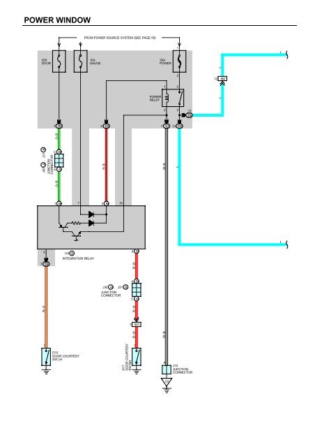
<strong>POWER</strong> <strong>WINDOW</strong><br />
FROM <strong>POWER</strong> SOURCE SYSTEM (SEE PAGE 50)<br />
1<br />
L<br />
25A<br />
DOOR<br />
10A<br />
GAUGE<br />
30A<br />
<strong>POWER</strong><br />
1 5<br />
10<br />
IB2<br />
2 3<br />
1<br />
1D<br />
5<br />
1G<br />
7<br />
1J<br />
13<br />
1G<br />
G- B G- B<br />
C<br />
A<br />
B<br />
A<br />
R- B<br />
W- B<br />
L<br />
1 B<br />
7<br />
3 B<br />
10<br />
L<br />
7<br />
1S<br />
INTEGRATION RELAY<br />
W- B<br />
R- G<br />
L<br />
2<br />
<strong>POWER</strong><br />
RELAY<br />
L<br />
12<br />
1G<br />
B<br />
J30 A , J31<br />
JUNCTION<br />
CONNECTOR<br />
6<br />
I18 B<br />
6<br />
R- W<br />
B<br />
A<br />
B<br />
J30<br />
A , J31<br />
JUNCTION<br />
CONNECTOR<br />
B<br />
C<br />
A<br />
R- W<br />
3<br />
IM1<br />
R- W<br />
1<br />
D10<br />
DOOR COURTESY<br />
SW LH<br />
D11<br />
DOOR COURTESY<br />
SW RH<br />
1<br />
A<br />
J10<br />
JUNCTION<br />
CONNECTOR<br />
IG
L<br />
L<br />
P 7<br />
<strong>POWER</strong> <strong>WINDOW</strong> MASTER SW<br />
9<br />
BW<br />
FRONT LH<br />
FRONT RH<br />
DOWN<br />
<strong>WINDOW</strong> LOCK SW<br />
IC<br />
LOCK<br />
NORMAL<br />
E<br />
DU<br />
DD<br />
PU<br />
PD<br />
1<br />
3 4<br />
8 10<br />
W- B<br />
G<br />
R<br />
11 IB2<br />
5 IB2<br />
G- W<br />
R- L<br />
G- W<br />
W- B<br />
R- L<br />
L<br />
20 IB1<br />
G- W<br />
4 IL2<br />
5 IL2<br />
6 IL2<br />
G- W<br />
R- L<br />
R- L<br />
L L<br />
W- B<br />
7 1G<br />
3 1V<br />
G<br />
R<br />
UP<br />
G<br />
5 2 4<br />
SU SD B<br />
U<br />
D<br />
3 1<br />
R<br />
DOWN<br />
P 6<br />
<strong>POWER</strong> <strong>WINDOW</strong> CONTROL<br />
SW FRONT RH<br />
W- B<br />
1 2<br />
M<br />
P 8<br />
<strong>POWER</strong> <strong>WINDOW</strong><br />
MOTOR FRONT LH<br />
2 1<br />
M<br />
P 9<br />
<strong>POWER</strong> <strong>WINDOW</strong> MOTOR<br />
FRONT RH<br />
IE
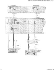
<strong>POWER</strong> <strong>WINDOW</strong><br />
SYSTEM OUTLINE<br />
With the ignition SW turned on, current flows through the GAUGE fuse to TERMINAL 7 of the integration relay to TERMINA<br />
(B) 3 to TERMINAL 1 of the power relay to TERMINAL 2 to GROUND, this activates the relay and the current flowing to<br />
TERMINAL 5 of the relay from the <strong>POWER</strong> fuse flows to TERMINAL 3 of the relay to TERMINAL 9 of the power window<br />
master SW.<br />
1. MANUAL OPERATION (DRIVER’S <strong>WINDOW</strong>)<br />
With the ignition SW turned on and with the power window master SW (Driver’s) in UP position, the current flowing from<br />
TERMINAL 9 of the power window master SW flows to TERMINAL 3 of the master SW to TERMINAL 1 of the power window<br />
motor to TERMINAL 2 to TERMINAL 4 of the master SW to TERMINAL 1 to GROUND and causes the power window motor<br />
to rotate in the up direction. The window ascends only while the SW is being pushed.<br />
In down operation, the flow of current from TERMINAL 9 of the power window master SW to TERMINAL 4 of the master SW<br />
causes the flow of current from TERMINAL 2 of the power window motor to TERMINAL 1 to TERMINAL 3 of the master SW<br />
to TERMINAL 1 to GROUND, flowing in the opposite detection to manual up operation and causing the motor to rotate in<br />
reverse, lowering the window.<br />
2. AUTO DOWN OPERATION (DRIVER’S <strong>WINDOW</strong>)<br />
When the driver’s window SW is pushed strongly to the down side, the current flowing to TERMINAL 9 of the power window<br />
master SW flows to the down contact point and auto down contact point of the driver’s SW.<br />
This activates the relay (Down side) inside the power window master SW and the hold circuit also turns on at the same time,<br />
so the relay (Down side) remains activated even when the SW is released.<br />
Current flows at this time from TERMINAL 9 of the power window master SW to TERMINAL 4 to TERMINAL 2 of the power<br />
window motor to TERMINAL 1 to TERMINAL 3 of the power window master SW to TERMINAL 1 to GROUND, so the motor<br />
continues to operate until the driver’s window is fully down.<br />
When the driver’s window finishes down operation and the hold circuit goes off, so the relay (Down side) also turns off. This<br />
stops the current flowing from TERMINAL 9 of the power window master SW to TERMINAL 4 is cut off, so the power window<br />
motor stops and auto down operation stops.<br />
When the driver’s SW is pulled to the up side during auto down operation, the hold circuit is turned off so the current flowing<br />
from TERMINAL 9 of the power window master SW to TERMINAL 4 is cut off and the power window motor stops. If the SW<br />
remains pulled up the relay (Up side) is activated, so current flows from TERMINAL 9 of the power window master SW to<br />
TERMINAL 3 to TERMINAL 1 of the power window motor to TERMINAL 2 to TERMINAL 4 to TERMINAL1 to GROUND, the<br />
power window motor rotates in the up direction and manual up operation occurs while the SW is pulled up.<br />
3. MANUAL OPERATION (FRONT RH <strong>WINDOW</strong>)<br />
With the power window control SW front RH pulled to the up side, the current flowing from TERMINAL 4 of the power window<br />
control SW flows to TERMINAL 3 of the power window control SW to TERMINAL 2 of the power window motor to TERMINAL<br />
1 to TERMINAL 1 of the power window control SW to TERMINAL 2 to TERMINAL 10 of the master SW to TERMINAL 1 to<br />
GROUND and causes the power window motor front RH to rotate in the up direction. The up operation continues only while<br />
the power window SW is pulled to the up side. When the window descends, the current flowing to the motor flows in the<br />
opposite direction, from TERMINAL 1 to TERMINAL 2, and the motor rotates in reverse. When the window lock SW is<br />
pushed to the lock side, the ground circuit to the front RH window becomes open.<br />
As a result, even if Open/Close operation of the front RH window is tried, the current from TERMINAL 1 of the power window<br />
master SW is not grounded and the motor does not rotate, so the front RH window can not be operated and window lock<br />
occurs.<br />
4. KEY OFF <strong>POWER</strong> <strong>WINDOW</strong> OPERATION<br />
With the ignition SW turned from on to off, the integration relay operates and current flows from the DOOR fuse to<br />
TERMINAL (B) 1 of the relay to TERMINAL (B) 3 to TERMINAL 1 of the power relay to TERMINAL 2 to GROUND for about<br />
43 seconds. The same as normal operation, the current flows from the <strong>POWER</strong> fuse to TERMINAL 5 of the power relay to<br />
TERMINAL 3 to TERMINAL 9 of the power window master SW and TERMINAL 4 of the power window control SW. As a<br />
result, for about 43 seconds after the ignition SW is turned off, the functioning of this relay makes it possible to raise and<br />
lower the power window. Also, by opening the front doors (Door open detection SW on) within about 43 seconds after turning<br />
the ignition SW to off, a signal is input to TERMINAL 6 or (B) 6 of the integration relay. As a result, the relay turned off, and<br />
up and down movement of the power window stops.
SERVICE HINTS<br />
P7 <strong>POWER</strong> <strong>WINDOW</strong> MASTER SW<br />
9-GROUND : Approx. 12 volts with the ignition SW at ON position or key off power window operation<br />
1-GROUND : Always continuity<br />
3-GROUND : Approx. 12 volts with the ignition SW on and the master SW (Driver’s window) at UP position<br />
4-GROUND : Approx. 12 volts with the ignition SW on and the master SW (Driver’s window)<br />
at DOWN or AUTO DOWN position<br />
<strong>WINDOW</strong> LOCK SW<br />
Open with the window lock SW at LOCK position<br />
: PARTS LOCATION<br />
Code See Page Code See Page Code See Page<br />
D10 32 J30 A 31 P8 33<br />
D11 32 J31 B 31 P9 33<br />
I18 B 30 P6 33<br />
J10 31 P7 33<br />
,,,<br />
,,, : JUNCTION BLOCK AND WIRE HARNESS CONNECTOR<br />
,,,<br />
Code See Page Junction Block and Wire Harness (Connector Location)<br />
1D<br />
1G<br />
20 Instrument Panel Wire and Instrument Panel J/B (Lower Finish Panel)<br />
1J 20 Cowl Wire and Instrument Panel J/B (Lower Finish Panel)<br />
1S 20 Floor Wire and Instrument Panel J/B (Lower Finish Panel)<br />
1V 20 Cowl Wire and Instrument Panel J/B (Lower Finish Panel)<br />
: CONNECTOR JOINING WIRE HARNESS AND WIRE HARNESS<br />
Code See Page Joining Wire Harness and Wire Harness (Connector Location)<br />
IB1<br />
IB2<br />
40 Front Door LH Wire and Instrument Panel Wire (Left Kick Panel)<br />
IL2 42 Front Door RH Wire and Instrument Panel Wire (Right Kick Panel)<br />
IM1 42 Floor No.2 Wire and Instrument Panel Wire (Right Kick Panel)<br />
: GROUND POINTS<br />
Code See Page Ground Points Location<br />
IE 40 Cowl Side Panel LH<br />
IG 40 Instrument Panel Brace LH<br />
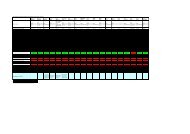
D10, D11 I18 (B) J10 J30 (A)<br />
BLACK<br />
1<br />
1 X 3 XX <br />
X X X <br />
A A<br />
A A A A A A C C<br />
<br />
(Hint : See Page 7)<br />
(Hint : See Page 7)<br />
J31 (B) P6 P7 P8, P9<br />
BLACK<br />
A A C C<br />
<br />
1 2 3 4 5<br />
(Hint : See Page 7)<br />
1 3 4<br />
X X 8 9 10 1 2<br />
(Hint : See Page 7)