Page 1 of 18 On Board Diagnostics PCED 7/25/2009 http://www ...
Page 1 of 18 On Board Diagnostics PCED 7/25/2009 http://www ...
Page 1 of 18 On Board Diagnostics PCED 7/25/2009 http://www ...

You also want an ePaper? Increase the reach of your titles
YUMPU automatically turns print PDFs into web optimized ePapers that Google loves.
<strong>On</strong> <strong>Board</strong> <strong>Diagnostics</strong> <strong>PCED</strong><br />
<strong>http</strong>://<strong>www</strong>.fordtechservice.dealerconnection.com/pubs/content/~WV52/~MUS~LEN/14/...<br />
<strong>Page</strong> 1 <strong>of</strong> <strong>18</strong><br />
7/<strong>25</strong>/<strong>2009</strong><br />
2005 <strong>PCED</strong> <strong>On</strong> <strong>Board</strong> <strong>Diagnostics</strong> SECTION 5: Pinpoint Tests<br />
Procedure revision date: 05/20/2008<br />
KB: Fuel Pump Driver Module<br />
KB: Introduction<br />
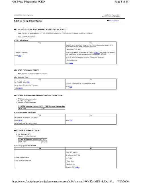
KB1 DTC P1233: IS DTC P1233 PRESENT IN THE KOEO SELF-TEST?<br />
Note: The Ford GT is equipped with 2 FPDMs. DTC P1233 applies to the FPDM mounted in the upper position on the bracket.<br />
Carry out the KOEO self-test.<br />
Is DTC P1233 present?<br />
Yes<br />
The PCM is now receiving a signal from the FPDM. <strong>On</strong>e possible cause <strong>of</strong> DTC<br />
P1233 is that the IFS switch was tripped, then reset.<br />
No<br />
If the engine is a no start:<br />
A hard fault is present.<br />
GO to KB2 .<br />
DISREGARD the DTC at this time. RETURN to Section 3 and continue as directed.<br />
After repairing the no start, to diagnose intermittent causes <strong>of</strong> P1233,<br />
RETURN to this test step and follow the, if the engine starts path.<br />
If the engine starts:<br />
GO to KB<strong>18</strong> .<br />
KB2 DOES THE ENGINE START?<br />
Note: The Ford GT starts with 1 FPDM disabled.<br />
Does the engine start?<br />
Yes<br />
For Ford GT, GO to KB3 .<br />
For all others, To check the FPM circuit,<br />
GO to KB14 .<br />
No<br />
Verify the IFS switch is set (button pressed). If OK,<br />
GO to KB3 .<br />
KB3 CHECK VOLTAGE AND GROUND CIRCUITS TO THE FPDM<br />
FPDM connector disconnected.<br />
Key ON, engine OFF.<br />
Measure the voltage between:<br />
( + ) FPDM Connector, Harness Side ( - ) FPDM Connector, Harness Side<br />
FPDM PWR<br />
GND<br />
Is the voltage greater than 10.5 V?<br />
For Ford GT, To check the FPM circuit,<br />
Yes<br />
No<br />
GO to KB14 .<br />
GO to KB4 .<br />
For all others, INSTALL a new FPDM.<br />
KB4 CHECK VOLTAGE TO FPDM<br />
Key ON, engine OFF.<br />
Measure the voltage between:<br />
( + ) FPDM Connector, Harness Side ( - )<br />
FPDM PWR<br />
Ground<br />
Is the voltage greater than 10.5 V?<br />
Yes<br />
No<br />
Key in OFF position.<br />
REPAIR the open circuit.<br />
(Open FPDM ground circuit).<br />
No voltage to the FPDM.<br />
For F-150,<br />
F-Super Duty,<br />
Expedition, and<br />
Navigator, GO to KB10 .
<strong>On</strong> <strong>Board</strong> <strong>Diagnostics</strong> <strong>PCED</strong><br />
<strong>http</strong>://<strong>www</strong>.fordtechservice.dealerconnection.com/pubs/content/~WV52/~MUS~LEN/14/...<br />
<strong>Page</strong> 2 <strong>of</strong> <strong>18</strong><br />
7/<strong>25</strong>/<strong>2009</strong><br />
For all others, GO to KB5 .<br />
KB5 CHECK THE B+ VOLTAGE TO THE FPDM POWER SUPPLY RELAY<br />
FPDM PWR Relay connector disconnected.<br />
Measure the voltage between:<br />
( + ) FPDM PWR Relay Connector, Harness Side ( - )<br />
B+ Ground<br />
Is the voltage greater than 10.5 V?<br />
GO to KB6 .<br />
Yes<br />
B+ circuit fault. CHECK the condition <strong>of</strong> the related fuse/fuse links. If OK, REPAIR<br />
the open circuit. If the fuse/fuse link is damaged, CHECK the circuit for short to<br />
ground before replacing.<br />
No<br />
KB6 CHECK THE VPWR VOLTAGE TO FPDM POWER SUPPLY RELAY<br />
Key ON, engine OFF.<br />
Measure the voltage between:<br />
( + ) FPDM PWR Relay Connector, Harness Side ( - )<br />
VPWR<br />
Ground<br />
Is the voltage greater than 10.5 V?<br />
GO to KB7 .<br />
Yes<br />
REPAIR the open circuit.<br />
No<br />
KB7 CHECK FOR GROUND TO THE FPDM POWER SUPPLY RELAY<br />
Measure the resistance between:<br />
( + ) FPDM PWR Relay Connector, Harness Side ( - )<br />
GND<br />
Ground<br />
Is the resistance less than 5 ohms?<br />
GO to KB8 .<br />
Yes<br />
REPAIR the open circuit.<br />
No<br />
KB8 CHECK THE FPDM PWR CIRCUIT FOR AN OPEN IN THE HARNESS<br />
Measure the resistance between:<br />
( + ) FPDM Connector, Harness Side ( - ) FPDM PWR Relay Connector, Harness Side<br />
FPDM PWR<br />
FPDM PWR<br />
Is the resistance less than 5 ohms?<br />
Yes<br />
INSTALL a new FPDM relay. GO to KB9 .<br />
No<br />
KB9 ISOLATE THE OPEN IN THE FPDM CIRCUIT<br />
IFS Switch connector disconnected.<br />
Measure the resistance between:<br />
( + ) FPDM Connector, Harness Side ( - ) IFS Switch Connector, Harness Side<br />
FPDM PWR<br />
FPDMPWR-B<br />
Measure the resistance between:<br />
( + ) FPDM PWR Relay Connector, Harness Side ( - ) IFS Switch Connector, Harness Side<br />
FPDM PWR<br />
FPDMPWR-A<br />
Is the resistance less than 5 ohms?<br />
INSTALL a new IFS switch.<br />
Yes<br />
VERIFY the IFS switch is set (button pressed).<br />
REPAIR the open circuit.<br />
No
<strong>On</strong> <strong>Board</strong> <strong>Diagnostics</strong> <strong>PCED</strong><br />
<strong>http</strong>://<strong>www</strong>.fordtechservice.dealerconnection.com/pubs/content/~WV52/~MUS~LEN/14/...<br />
<strong>Page</strong> 3 <strong>of</strong> <strong>18</strong><br />
7/<strong>25</strong>/<strong>2009</strong><br />
KB10 CHECK THE FUEL PUMP FUSE<br />
Note: These steps are for applications with FPDM PWR relay integral to the PDJB.<br />
Check the FPDM power supply relay fuse. (located on the PDJB).<br />
Is the fuse OK?<br />
GO to KB11 .<br />
Yes<br />
INSTALL a new fuse.<br />
CHECK the associated circuits for a short to ground before installing the fuse.<br />
No<br />
KB11 CHECK VOLTAGE TO IFS<br />
IFS Switch connector disconnected.<br />
Key ON, engine OFF.<br />
Measure the voltage between:<br />
( + ) IFS Switch Connector, Harness Side ( - )<br />
FPDMPWR-A<br />
Ground<br />
Is the voltage greater than 10.5 V?<br />
Key in OFF position.<br />
GO to KB13 .<br />
Yes<br />
Key in OFF position.<br />
GO to KB12 .<br />
No<br />
KB12 CHECK THE FPDM PWR CIRCUIT FOR AN OPEN BETWEEN THE IFS AND PDJB<br />
PDJB connector disconnected. (connector with FPDM PWR circuit)<br />
Measure the resistance between:<br />
( + ) IFS Switch Connector, Harness Side ( - ) PDJB Connector, Harness Side<br />
FPDMPWR-A<br />
FPDM PWR<br />
Is the resistance less than 5 ohms?<br />
CHECK the fuel pump fuse.<br />
If OK, INSTALL a new FP RLY/PDJB.<br />
Yes<br />
REPAIR the open circuit.<br />
No<br />
KB13 CHECK THE IFS FOR AN OPEN<br />
Measure the resistance between:<br />
( + ) IFS Switch Connector, Component Side ( - ) IFS Switch Connector, Component Side<br />
FPDMPWR-A<br />
FPDMPWR-B<br />
Is the resistance less than 5 ohms?<br />
REPAIR the open circuit.<br />
(Open FPDM PWR circuit).<br />
Yes<br />
INSTALL a new IFS switch.<br />
No<br />
KB14 CHECK THE FPM CIRCUIT FOR AN OPEN IN THE HARNESS<br />
FPDM connector disconnected.<br />
PCM connector disconnected.<br />
Measure the resistance between:<br />
( + ) FPDM Connector, Harness Side ( - ) PCM Connector, Harness Side<br />
FPM<br />
FPM<br />
Is the resistance less than 5 ohms?<br />
GO to KB15 .<br />
Yes<br />
REPAIR the open circuit.<br />
No<br />
KB15 CHECK THE FPM CIRCUIT FOR A SHORT TO VOLTAGE IN THE HARNESS
<strong>On</strong> <strong>Board</strong> <strong>Diagnostics</strong> <strong>PCED</strong><br />
<strong>http</strong>://<strong>www</strong>.fordtechservice.dealerconnection.com/pubs/content/~WV52/~MUS~LEN/14/...<br />
<strong>Page</strong> 4 <strong>of</strong> <strong>18</strong><br />
7/<strong>25</strong>/<strong>2009</strong><br />
Key ON, engine OFF.<br />
Measure the voltage between:<br />
( + ) FPDM Connector, Harness Side ( - )<br />
FPM<br />
Ground<br />
Is the voltage less than 1 V?<br />
Key in OFF position.<br />
GO to KB16 .<br />
Yes<br />
REPAIR the short circuit.<br />
No<br />
KB16 CHECK THE FPM CIRCUIT FOR A SHORT TO GROUND IN THE HARNESS<br />
Measure the resistance between:<br />
( + ) FPDM Connector, Harness Side ( - )<br />
FPM<br />
Ground<br />
Is the resistance greater than 10K ohms?<br />
GO to KB17 .<br />
Yes<br />
REPAIR the short circuit.<br />
No<br />
KB17 CHECK FOR FPM OUTPUT FROM THE FPDM<br />
FPDM connector connected.<br />
Key ON, engine OFF.<br />
Note: It is OK for the voltage to cycle below this range and then return within range.<br />
Measure the voltage between:<br />
( + ) PCM Connector, Harness Side ( - )<br />
FPM<br />
Ground<br />
Is the voltage between 0.02 - 1 V?<br />
Yes<br />
INSTALL a new PCM. REFER to Section 2, Flash Electrically Erasable<br />
Programmable Read <strong>On</strong>ly Memory (EEPROM).<br />
INSTALL a new FPDM.<br />
No<br />
KB<strong>18</strong> CHECK CIRCUITS THAT MAY CAUSE AN INTERMITTENT LOSS OF VOLTAGE SUPPLY TO THE FPDM<br />
Note: Be aware that P1233 could be set if the inertia fuel shut<strong>of</strong>f IFS switch is tripped then reset.<br />
Key ON, engine OFF.<br />
Access the PCM and monitor the FPM PID.<br />
Note: With no fault detected, the FPDM sends a 50% duty cycle (all OK) to the PCM on the FPM circuit. Depending on diagnostic tools, the FPM PID may display 50%, or a random<br />
value that is fluctuating between 85% and 115%.<br />
Observe the FPM PID for an indication <strong>of</strong> a fault while completing the following: (look for the FPM PID to change from the 50 percent value, or to stop fluctuating).<br />
Shake, wiggle, and bend the following circuits:<br />
FPDM GND<br />
FPDM PWR circuit to the FPDM<br />
FPM circuit between the FPDM and the PCM<br />
B+ and ground circuits to the FPDM power supply relay<br />
Lightly tap on the IFS to simulate road shock<br />
Lightly tap on the FPDM to simulate road shock<br />
Lightly tap on the FPDM power supply relay to simulate road shock<br />
Key in OFF position.<br />
Is a concern present?<br />
Yes<br />
ISOLATE the fault and REPAIR as necessary.<br />
No<br />
Unable to duplicate or identify the fault at this time.<br />
GO to Z1 .<br />
KB19 DTC P1235: IS DTC P1235 PRESENT IN THE KOEO SELF-TEST?<br />
Note: The Ford GT is equipped with 2 FPDMs. DTC P1235 applies to the FPDM mounted in the upper position on the bracket.<br />
Note: For ETC applications, check if ETC DTC P2105 is present. An ETC system concern could cause P1235, and should be diagnosed first.<br />
Carry out the KOEO self-test.
<strong>On</strong> <strong>Board</strong> <strong>Diagnostics</strong> <strong>PCED</strong><br />
<strong>http</strong>://<strong>www</strong>.fordtechservice.dealerconnection.com/pubs/content/~WV52/~MUS~LEN/14/...<br />
<strong>Page</strong> 5 <strong>of</strong> <strong>18</strong><br />
7/<strong>25</strong>/<strong>2009</strong><br />
Is DTC P1235 present?<br />
Yes<br />
For LS, and<br />
No<br />
GO to KB20 .<br />
Thunderbird, GO to KB29 .<br />
For all others, GO to KB30 .<br />
KB20 CHECK THE FP CIRCUIT FOR AN OPEN IN THE HARNESS<br />
Note: For the LS and Thunderbird the FPDM functions are incorporated into the rear electronics module (REM). In the following steps, if directed to carry out an action with the<br />
FPDM, carry out the action with the REM.<br />
FPDM connector disconnected.<br />
PCM connector disconnected.<br />
Measure the resistance between:<br />
( + ) PCM Connector, Harness Side ( - ) FPDM Connector, Harness Side<br />
FP<br />
FP<br />
Is the resistance less than 5 ohms?<br />
GO to KB21 .<br />
Yes<br />
REPAIR the open circuit.<br />
No<br />
KB21 CHECK THE FP CIRCUIT FOR A SHORT TO VOLTAGE IN THE HARNESS<br />
FPDM2 connector disconnected (Ford GT).<br />
Key ON, engine OFF.<br />
Measure the voltage between:<br />
( + ) FPDM Connector, Harness Side ( - )<br />
FP<br />
Ground<br />
Is the voltage less than 1 V?<br />
Key in OFF position.<br />
GO to KB22 .<br />
Yes<br />
REPAIR the short circuit.<br />
No<br />
KB22 CHECK THE FP CIRCUIT FOR A SHORT TO GROUND<br />
Measure the resistance between:<br />
( + ) FPDM Connector, Harness Side ( - )<br />
FP<br />
Ground<br />
Is the resistance greater than 10K ohms?<br />
For Aviator,<br />
Crown Victoria,<br />
Focus,<br />
Grand Marquis,<br />
Yes<br />
No<br />
Sable,<br />
Taurus, and<br />
REPAIR the short circuit.<br />
Town Car, GO to KB23 .<br />
For LS, and<br />
Thunderbird, GO to KB<strong>25</strong> .<br />
For all others, GO to KB24 .<br />
KB23 CHECK THE FP CIRCUIT IN THE FPDM<br />
FPDM connector connected.<br />
Key ON, engine OFF.<br />
Measure the voltage between:<br />
( + ) PCM Connector, Harness Side ( - )<br />
FP<br />
Ground
<strong>On</strong> <strong>Board</strong> <strong>Diagnostics</strong> <strong>PCED</strong><br />
<strong>http</strong>://<strong>www</strong>.fordtechservice.dealerconnection.com/pubs/content/~WV52/~MUS~LEN/14/...<br />
<strong>Page</strong> 6 <strong>of</strong> <strong>18</strong><br />
7/<strong>25</strong>/<strong>2009</strong><br />
Is the voltage between 4.5 - 5.5 V?<br />
Yes<br />
INSTALL a new PCM. REFER to Section 2, Flash Electrically Erasable<br />
Programmable Read <strong>On</strong>ly Memory (EEPROM).<br />
INSTALL a new FPDM.<br />
No<br />
KB24 CHECK THE FP CIRCUIT IN THE FPDM<br />
FPDM connector connected.<br />
FPDM2 connector disconnected (Ford GT).<br />
Key ON, engine OFF.<br />
Measure the voltage between:<br />
( + ) PCM Connector, Harness Side ( - )<br />
FP<br />
Ground<br />
Is the voltage greater than 10.5 V?<br />
Yes<br />
INSTALL a new PCM. REFER to Section 2, Flash Electrically Erasable<br />
Programmable Read <strong>On</strong>ly Memory (EEPROM).<br />
INSTALL a new FPDM.<br />
No<br />
KB<strong>25</strong> CHECK THE FPF PID<br />
PCM connector connected.<br />
REM connector connected.<br />
Key ON, engine OFF.<br />
Access the PCM and monitor the FPF PID.<br />
While viewing the FPF PID, check if PID indicates YES sometime within 20 seconds.<br />
Does the FPF PID indicate YES sometime within 20 seconds?<br />
Yes<br />
GO to KB28 . GO to KB26 .<br />
No<br />
KB26 CHECK THE FP PID<br />
Access the PCM and monitor the FP PID.<br />
Is the duty cycle between 70 - 80%?<br />
GO to KB27 .<br />
Yes<br />
Key in OFF position. INSTALL a new PCM. REFER to Section 2, Flash Electrically<br />
Erasable Programmable Read <strong>On</strong>ly Memory (EEPROM).<br />
No<br />
KB27 CHECK THE PWM_DC1 PID<br />
Access the REM and monitor the PWM_DC1 PID.<br />
Is the duty cycle between 70 - 80%?<br />
Key in OFF position.<br />
Yes<br />
No<br />
No fault found.<br />
DISREGARD DTC P1235 at this time.<br />
INSTALL a new REM.<br />
RETURN to Section 3 , Symptom Charts for further direction.<br />
KB28 CHECK THE REM CIRCUITRY VOLTAGE ON THE FP CIRCUIT AT THE PCM<br />
Key in OFF position.<br />
PCM connector disconnected.<br />
Key ON, engine OFF.<br />
Measure the voltage between:<br />
( + ) PCM Connector, Harness Side ( - )<br />
FP<br />
Ground<br />
Is the voltage greater than 8 V?<br />
Yes<br />
INSTALL a new PCM. REFER to Section 2, Flash Electrically Erasable<br />
Programmable Read <strong>On</strong>ly Memory (EEPROM).<br />
INSTALL a new REM.<br />
No
<strong>On</strong> <strong>Board</strong> <strong>Diagnostics</strong> <strong>PCED</strong><br />
<strong>http</strong>://<strong>www</strong>.fordtechservice.dealerconnection.com/pubs/content/~WV52/~MUS~LEN/14/...<br />
<strong>Page</strong> 7 <strong>of</strong> <strong>18</strong><br />
7/<strong>25</strong>/<strong>2009</strong><br />
KB29 CHECK THE FP CIRCUIT(S) FOR INTERMITTENT CONCERNS<br />
Key ON, engine OFF.<br />
Access the REM and monitor the PWM_DC1 PID.<br />
Observe the PWM_DC1 PID for an indication <strong>of</strong> a fault while completing the following: (the PID value changes when a fault is detected).<br />
Shake, wiggle, and bend the FP circuit between the PCM and REM<br />
Lightly tap on the FPDM to simulate road shock<br />
Is a concern present?<br />
Yes<br />
Key in OFF position.<br />
No<br />
ISOLATE the fault and REPAIR as necessary.<br />
Unable to duplicate or identify the fault at this time.<br />
GO to Z1 .<br />
KB30 CHECK THE FP CIRCUIT FOR AN INTERMITTENT OPEN OR SHORTS<br />
Key ON, engine OFF.<br />
Access the PCM and monitor the FPM PID.<br />
Note: With no fault detected, the FPDM sends a 50% duty cycle (all OK) to the PCM on the FPM circuit. Depending on diagnostic tools, the FPM PID may display 50%, or a random<br />
value that is fluctuating between 85% and 115%.<br />
Observe the FPM PID for an indication <strong>of</strong> a fault while completing the following: (look for the FPM PID to change from the 50% value, or to stop fluctuating).<br />
Shake, wiggle, and bend the FP circuit between FPDM and the PCM<br />
Lightly tap on the FPDM to simulate road shock<br />
Is a concern present?<br />
Yes<br />
Key in OFF position.<br />
No<br />
ISOLATE the fault and REPAIR as necessary.<br />
Unable to duplicate or identify the fault at this time.<br />
GO to Z1 .<br />
KB31 DTC P1237: IS DTC P1237 PRESENT IN THE KOEO SELF-TEST?<br />
Note: The Ford GT is equipped with 2 FPDMs. DTC P1237 applies to the FPDM mounted in the upper position on the bracket.<br />
Carry out the KOEO self-test.<br />
Is DTC P1237 present?<br />
Yes<br />
DTC P1237 is possibly intermittent.<br />
No<br />
A hard fault is present.<br />
GO to KB32 .<br />
For LS, and<br />
Thunderbird, GO to KB49 .<br />
For all others, GO to KB38 .<br />
KB32 DOES THE ENGINE START?<br />
Note: The Ford GT starts with 1 FPDM disabled.<br />
FPDM2 connector disconnected (Ford GT).<br />
Does the engine start?<br />
For LS, and<br />
Thunderbird, GO to KB52 .<br />
For all others, GO to KB41 .<br />
Yes<br />
For LS, and<br />
Thunderbird, GO to KB43 .<br />
For all others, GO to KB33 .<br />
No<br />
KB33 CHECK FPPWR, FPRTN AND INTERNAL FUEL PUMP CIRCUIT RESISTANCE<br />
FPDM connector disconnected.<br />
Measure the resistance between:<br />
( + ) FPDM Connector, Harness Side ( - ) FPDM Connector, Harness Side<br />
FPPWR<br />
FPRTN<br />
Is the resistance less than 10 ohms?<br />
Yes<br />
No
<strong>On</strong> <strong>Board</strong> <strong>Diagnostics</strong> <strong>PCED</strong><br />
<strong>http</strong>://<strong>www</strong>.fordtechservice.dealerconnection.com/pubs/content/~WV52/~MUS~LEN/14/...<br />
<strong>Page</strong> 8 <strong>of</strong> <strong>18</strong><br />
7/<strong>25</strong>/<strong>2009</strong><br />
GO to KB34 .<br />
ISOLATE the concern,<br />
GO to KB37 .<br />
KB34 CHECK THE FPRTN CIRCUIT FOR A SHORT TO VOLTAGE IN THE HARNESS<br />
Key ON, engine OFF.<br />
Measure the voltage between:<br />
( + ) FPDM Connector, Harness Side ( - )<br />
FPRTN<br />
Ground<br />
Is the voltage less than 1 V?<br />
GO to KB35 .<br />
Yes<br />
REPAIR the short circuit.<br />
No<br />
KB35 CHECK THE FPPWR CIRCUIT FOR A SHORT TO GROUND IN THE HARNESS<br />
FP connector disconnected.<br />
Measure the resistance between:<br />
( + ) FPDM Connector, Harness Side ( - )<br />
FPPWR<br />
Ground<br />
Is the resistance greater than 10K ohms?<br />
GO to KB36 .<br />
Yes<br />
REPAIR the short circuit.<br />
No<br />
KB36 CHECK FOR VOLTAGE TO FP<br />
FPDM connector connected.<br />
FP connector disconnected.<br />
Key ON, engine OFF.<br />
Note: During Output Test Mode, the fuel pump stays commanded on for only about 5 seconds.<br />
Enter output test mode. Refer to Section 2, Output Test Mode (OTM).<br />
Command the outputs ON.<br />
Measure the voltage between:<br />
( + ) FP Connector, Harness Side ( - ) FP Connector, Harness Side<br />
FPPWR<br />
FPRTN<br />
Is the voltage greater than 10 V?<br />
Yes<br />
VERIFY the vehicle battery was at a proper charge during the test.<br />
No<br />
INSTALL a new FP.<br />
VERIFY the pump ON command did not time out before the voltage check was<br />
made.<br />
If OK, INSTALL a new FPDM.<br />
KB37 ISOLATE THE OPEN IN THE FP CIRCUIT<br />
FP connector disconnected.<br />
Measure the resistance between:<br />
( + ) FP Connector, Harness Side ( - ) FPDM Connector, Harness Side<br />
FPPWR<br />
FPPWR<br />
FPRTN<br />
FPRTN<br />
Measure the resistance between:<br />
( + ) FP Connector, Component Side ( - ) FP Connector, Component Side<br />
FPPWR<br />
FPRTN<br />
Is the resistance less than 10 ohms?<br />
Yes<br />
Unable to duplicate or identify the fault at this time.<br />
REPAIR the open circuit.<br />
No<br />
GO to Z1 .<br />
If the open is internal to the pump, INSTALL a new FP.
<strong>On</strong> <strong>Board</strong> <strong>Diagnostics</strong> <strong>PCED</strong><br />
<strong>http</strong>://<strong>www</strong>.fordtechservice.dealerconnection.com/pubs/content/~WV52/~MUS~LEN/14/...<br />
<strong>Page</strong> 9 <strong>of</strong> <strong>18</strong><br />
7/<strong>25</strong>/<strong>2009</strong><br />
KB38 VERIFY THE DTC P1237 IS INTERMITTENT<br />
Key ON, engine OFF.<br />
Access the PCM and monitor the FPM PID.<br />
Is the FPM PID 75% (or varying between <strong>25</strong>0% and 400%)?<br />
A hard fault is present.<br />
GO to KB32 .<br />
Yes<br />
DTC P1237 is possibly intermittent.<br />
GO to KB39 .<br />
No<br />
KB39 CHECK THE FPPWR AND FPRTN CIRCUIT FOR AN INTERMITTENT OPEN OR SHORTS<br />
Key ON, engine OFF.<br />
Access the PCM and monitor the FPM PID.<br />
Note: With no fault detected, the FPDM sends a 50% duty cycle (all OK) to the PCM on the FPM circuit. Depending on diagnostic tools, the FPM PID may display 50%, or a random<br />
value that is fluctuating between 85% and 115%.<br />
Observe the FPM PID for an indication <strong>of</strong> a fault while completing the following: (look for the FPM PID to change from the 50% value, or to stop fluctuating).<br />
Shake, wiggle, and bend the FPPWR and FPRTN circuits between the FPDM and the FP<br />
Lightly tap on the FP and FPDM to simulate road shock<br />
Is a concern present?<br />
Yes<br />
ISOLATE the fault and REPAIR as necessary.<br />
Key in OFF position.<br />
GO to KB40 .<br />
No<br />
KB40 CHECK THE FPPWR CIRCUIT FOR A SHORT TO GROUND IN THE HARNESS<br />
FPDM connector disconnected.<br />
Connect a non-powered test lamp between:<br />
( + ) FPDM Connector, Harness Side ( - ) FPDM Connector, Harness Side<br />
FPPWR<br />
FPDM PWR<br />
Key ON, engine OFF.<br />
Note: The lamp turns ON when a fault is detected.<br />
Observe the test lamp for an indication <strong>of</strong> a fault while completing the following.<br />
Shake, wiggle, and bend the FPPWR circuit between the FPDM and the FP.<br />
Is a concern present?<br />
Yes<br />
Key in OFF position.<br />
No<br />
ISOLATE the fault and REPAIR as necessary.<br />
Unable to duplicate or identify the fault at this time.<br />
GO to Z1 .<br />
KB41 CHECK THE FPPWR CIRCUIT FOR A SHORT TO VOLTAGE IN THE HARNESS<br />
FPDM connector disconnected.<br />
Key ON, engine OFF.<br />
Measure the voltage between:<br />
( + ) FPDM Connector, Harness Side ( - )<br />
FPPWR<br />
Ground<br />
Is the voltage less than 1 V?<br />
GO to KB42 .<br />
Yes<br />
REPAIR the short circuit to PWR.<br />
No<br />
KB42 CHECK THE FPRTN CIRCUIT FOR A SHORT TO GROUND IN THE HARNESS<br />
FPDM connector disconnected.<br />
Key ON, engine OFF.<br />
Measure the voltage between:<br />
( + ) FPDM Connector, Harness Side ( - ) FPDM Connector, Harness Side<br />
FPDM PWR<br />
FPRTN
<strong>On</strong> <strong>Board</strong> <strong>Diagnostics</strong> <strong>PCED</strong><br />
<strong>http</strong>://<strong>www</strong>.fordtechservice.dealerconnection.com/pubs/content/~WV52/~MUS~LEN/14/...<br />
<strong>Page</strong> 10 <strong>of</strong> <strong>18</strong><br />
7/<strong>25</strong>/<strong>2009</strong><br />
Is the voltage less than 1 V?<br />
INSTALL a new FPDM.<br />
Yes<br />
REPAIR the short circuit to GND.<br />
No<br />
KB43 CHECK THE REM/FP PWR AND GROUND CIRCUIT TO REM PINS J1-1, J1-2<br />
Note: Verify the IFS switch is not tripped.<br />
REM-J1 connector disconnected.<br />
Key ON, engine OFF.<br />
Measure the voltage between:<br />
( + ) REM-J1 Connector, Harness Side ( - ) REM-J1 Connector, Harness Side<br />
REM/FP PWR<br />
GND<br />
Is the voltage greater than 10.5 V?<br />
Key in OFF position.<br />
Yes<br />
No<br />
For these applications, the FPDM functions are incorporated into the REM. In the<br />
following steps, if directed to carry out an action with the FPDM, carry out the action<br />
with the REM.<br />
GO to KB44 .<br />
GO to KB33 .<br />
KB44 CHECK THE REM/FP PWR CIRCUIT VOLTAGE TO THE REM USING CHASSIS GROUND AS A REFERENCE<br />
Key ON, engine OFF.<br />
Measure the voltage between:<br />
( + ) REM-J1 Connector, Harness Side ( - )<br />
REM/FP PWR<br />
Ground<br />
Is the voltage greater than 10.5 V?<br />
REPAIR the open circuit.<br />
(Open FPDM ground circuit).<br />
Yes<br />
Key in OFF position.<br />
GO to KB45 .<br />
No<br />
KB45 CHECK THE B+ VOLTAGE TO THE FP/REM POWER SUPPLY RELAY<br />
FP/REM PWR Relay connector disconnected.<br />
Measure the voltage between:<br />
( + ) FP/REM PWR Relay Connector, Harness Side ( - )<br />
B+ - Pin 3 Ground<br />
Is the voltage greater than 10.5 V?<br />
GO to KB46 .<br />
Yes<br />
B+ circuit fault. CHECK the condition <strong>of</strong> the related fuse/fuse links. If OK, REPAIR<br />
the open circuit. If the fuse/fuse link is damaged, CHECK the circuit for short to<br />
ground before replacing.<br />
No<br />
KB46 CHECK FOR IGN START/RUN VOLTAGE (THROUGH THE IFS SWITCH) TO THE RELAY HARNESS CONNECTOR<br />
REM-J3 connector disconnected.<br />
Key ON, engine OFF.<br />
Measure the voltage between:<br />
( + ) FP/REM PWR Relay Connector, Harness Side ( - )<br />
IGN START/RUN - Pin 2<br />
Ground<br />
Is the voltage greater than 10.5 V?<br />
Key in OFF position.<br />
GO to KB47 .<br />
Yes<br />
ISOLATE the concern,<br />
GO to KB51 .<br />
No<br />
KB47 CHECK THE GROUND CIRCUIT TO FP/REM PWR RLY<br />
Measure the resistance between:
<strong>On</strong> <strong>Board</strong> <strong>Diagnostics</strong> <strong>PCED</strong><br />
<strong>http</strong>://<strong>www</strong>.fordtechservice.dealerconnection.com/pubs/content/~WV52/~MUS~LEN/14/...<br />
<strong>Page</strong> 11 <strong>of</strong> <strong>18</strong><br />
7/<strong>25</strong>/<strong>2009</strong><br />
( + ) FP/REM PWR Relay Connector, Harness Side ( - )<br />
GND - Pin 1<br />
Ground<br />
Is the resistance less than 5 ohms?<br />
GO to KB48 .<br />
Yes<br />
REPAIR the open circuit.<br />
No<br />
KB48 CHECK REM/FP PWR CIRCUIT CONTINUITY<br />
Measure the resistance between:<br />
( + ) FP/REM PWR Relay Connector, Harness Side ( - ) REM-J1 Connector, Harness Side<br />
REM/FP PWR - Pin 5<br />
REM/FP PWR<br />
Is the resistance less than 5 ohms?<br />
INSTALL a new FP/REM PWR relay.<br />
Yes<br />
REPAIR the open circuit.<br />
No<br />
KB49 CHECK THE REMJ1 GND AND CIRCUITS ASSOCIATED WITH THE FPDM PWR RLY FOR INTERMITTENTS<br />
REMJ1 connector disconnected.<br />
Connect a non-powered test lamp between:<br />
( + ) REM-J1 Connector, Harness Side ( - ) REM-J1 Connector, Harness Side<br />
REM/FP PWR<br />
GND<br />
Key ON, engine OFF.<br />
Note: The lamp turns <strong>of</strong>f when a concern is present.<br />
Observe the test lamp for an indication <strong>of</strong> a fault while completing the following.<br />
Shake, wiggle, and bend the REM/FP PWR and GND circuits to REM<br />
Shake, wiggle, and bend the circuits going to the FPDM PWR RLY<br />
Lightly tap on the FPDM PWR RLY and IFS to simulate road shock<br />
Is a concern present?<br />
Yes<br />
ISOLATE the fault and REPAIR as necessary.<br />
Key in OFF position.<br />
GO to KB50 .<br />
No<br />
KB50 CHECK THE FPPWR AND FPRTN CIRCUIT(S) FOR INTERMITTENT CONCERNS<br />
Measure the resistance between:<br />
( + ) REM-J1 Connector, Harness Side ( - ) REM-J1 Connector, Harness Side<br />
FPPWR<br />
FPRTN<br />
Note: Resistance changes suddenly when a fault is detected.<br />
Observe the DMM for an indication <strong>of</strong> a concern while completing the following.<br />
Shake, wiggle, and bend the FPPWR and FPRTN circuits between the FP and the REM<br />
Measure the resistance between:<br />
( + ) REM-J1 Connector, Harness Side ( - )<br />
FPRTN<br />
Ground<br />
Note: Resistance changes suddenly when a fault is detected.<br />
Observe the DMM for an indication <strong>of</strong> a concern while completing the following.<br />
Shake, wiggle, and bend the FPPWR and FPRTN circuits between the FP and the REM<br />
Is a concern present?<br />
Yes<br />
ISOLATE the fault and REPAIR as necessary.<br />
No<br />
Unable to duplicate or identify the fault at this time.<br />
CONNECT the REM.<br />
GO to Z1 .<br />
KB51 ISOLATE THE OPEN IN THE IGN START/RUN CIRCUIT<br />
IFS Switch connector disconnected.
<strong>On</strong> <strong>Board</strong> <strong>Diagnostics</strong> <strong>PCED</strong><br />
<strong>http</strong>://<strong>www</strong>.fordtechservice.dealerconnection.com/pubs/content/~WV52/~MUS~LEN/14/...<br />
<strong>Page</strong> 12 <strong>of</strong> <strong>18</strong><br />
7/<strong>25</strong>/<strong>2009</strong><br />
Measure the resistance between:<br />
( + ) IFS Switch Connector, Component Side ( - ) IFS Switch Connector, Component Side<br />
IGN START/RUN-A<br />
IGN START/RUN-B<br />
Measure the resistance between:<br />
( + ) FPDM PWR Relay Connector, Harness Side ( - ) IFS Switch Connector, Harness Side<br />
IGN START/RUN<br />
IGN START/RUN-B<br />
Is the resistance less than 5 ohms?<br />
REPAIR the open circuit.<br />
Yes<br />
INSTALL a new IFS switch.<br />
No<br />
KB52 CHECK THE FPRTN CIRCUIT FOR A SHORT TO GROUND IN THE HARNESS<br />
REM-J1 connector disconnected.<br />
Key ON, engine OFF.<br />
Measure the voltage between:<br />
( + ) REM-J1 Connector, Harness Side ( - ) REM Connector, Harness Side<br />
REM/FP PWR<br />
FPRTN<br />
Is the voltage less than 1 V?<br />
GO to KB49 .<br />
Yes<br />
REPAIR the short circuit to GND.<br />
No<br />
KB53 CARRY OUT THE REM SELF-TEST TO VERIFY THE IFS SWITCH INPUT TO THE REM<br />
Carry out the REM self-test. Refer to the Workshop Manual Section 419-10, Multifunction Electronic Modules.<br />
Carry out the REM self-test.<br />
Is DTC B2172 present?<br />
Yes<br />
GO to KB54 . GO to A1 .<br />
No<br />
KB54 DTC B2172: CHECK THE IFS SWITCH INPUT CIRCUIT TO THE REM<br />
REM-J3 connector disconnected.<br />
Key ON, engine OFF.<br />
Measure the voltage between:<br />
( + ) REM-J3 Connector, Harness Side ( - )<br />
IFS<br />
Ground<br />
Is the voltage greater than 10.5 V?<br />
Key in OFF position.<br />
Yes<br />
No<br />
If the engine is a no start and REM DTC B2172 is received in on-demand self-test<br />
mode:<br />
INSTALL a new REM.<br />
If the engine starts or REM DTC B2172 is a continuous memory DTC:<br />
DTC is possibly intermittent.<br />
If the engine is a no start:<br />
RETURN to Section 3 to continue diagnosis.<br />
Key in OFF position.<br />
CHECK the IFS switch for an open.<br />
If OK,<br />
REPAIR the open circuit.<br />
If the engine starts:<br />
GO to Z1 .<br />
KB55 DTC P1234: IS DTC P1234 PRESENT IN THE KOEO SELF-TEST?<br />
Note: The Ford GT is equipped with 2 FPDMs. DTC P1234 applies to FPDM2, which is mounted in the lower position on the bracket.<br />
Carry out the KOEO self-test.<br />
Is DTC P1234 present?<br />
Yes<br />
No<br />
The PCM is now receiving a signal from FPDM2. <strong>On</strong>e possible cause <strong>of</strong> DTC P1234
<strong>On</strong> <strong>Board</strong> <strong>Diagnostics</strong> <strong>PCED</strong><br />
<strong>http</strong>://<strong>www</strong>.fordtechservice.dealerconnection.com/pubs/content/~WV52/~MUS~LEN/14/...<br />
<strong>Page</strong> 13 <strong>of</strong> <strong>18</strong><br />
7/<strong>25</strong>/<strong>2009</strong><br />
A hard fault is present.<br />
GO to KB56 .<br />
is that the IFS switch was tripped, then reset.<br />
GO to KB66 .<br />
KB56 CHECK VOLTAGE AND GROUND CIRCUITS TO THE FPDM2<br />
FPDM2 connector disconnected.<br />
Key ON, engine OFF.<br />
Measure the voltage between:<br />
( + ) FPDM2 Connector, Harness Side ( - ) FPDM2 Connector, Harness Side<br />
FPDM2 PWR - Pin 5 GND - Pin 3<br />
Is the voltage greater than 10.5 V?<br />
Key in OFF position.<br />
Yes<br />
No<br />
To check the FPM2 circuit,<br />
GO to KB57 .<br />
GO to KB62 .<br />
KB57 CHECK VOLTAGE TO FPDM2<br />
Measure the voltage between:<br />
( + ) FPDM2 Connector, Harness Side ( - )<br />
FPDM2 PWR - Pin 5<br />
Ground<br />
Is the voltage greater than 10.5 V?<br />
REPAIR the open circuit.<br />
Open FPDM2 ground circuit.<br />
Yes<br />
Key in OFF position.<br />
No voltage to FPDM2.<br />
GO to KB58 .<br />
No<br />
KB58 CHECK THE B+ VOLTAGE TO THE FPDM2 POWER SUPPLY RELAY<br />
FPDM2 PWR Relay connector disconnected.<br />
Measure the voltage between:<br />
( + ) FPDM2 PWR Relay Connector, Harness Side ( - )<br />
B+ - Pin 3 Ground<br />
Is the voltage greater than 10.5 V?<br />
GO to KB59 .<br />
Yes<br />
B+ circuit fault. CHECK the condition <strong>of</strong> the related fuse/fuse links. If OK, REPAIR<br />
the open circuit. If the fuse/fuse link is damaged, CHECK the circuit for short to<br />
ground before replacing.<br />
No<br />
KB59 CHECK THE VPWR VOLTAGE TO FPDM2 POWER SUPPLY RELAY<br />
Measure the voltage between:<br />
( + ) FPDM2 PWR Relay Connector, Harness Side ( - )<br />
VPWR - Pin 1<br />
Ground<br />
Is the voltage greater than 10.5 V?<br />
GO to KB60 .<br />
Yes<br />
REPAIR the open circuit.<br />
No<br />
KB60 CHECK FOR GROUND TO THE FPDM2 POWER SUPPLY RELAY<br />
Key in OFF position.<br />
Measure the resistance between:<br />
( + ) FPDM2 PWR Relay Connector, Harness Side ( - )<br />
GND - Pin 2<br />
Ground<br />
Is the resistance less than 5 ohms?<br />
Yes<br />
No
<strong>On</strong> <strong>Board</strong> <strong>Diagnostics</strong> <strong>PCED</strong><br />
<strong>http</strong>://<strong>www</strong>.fordtechservice.dealerconnection.com/pubs/content/~WV52/~MUS~LEN/14/...<br />
<strong>Page</strong> 14 <strong>of</strong> <strong>18</strong><br />
7/<strong>25</strong>/<strong>2009</strong><br />
GO to KB61 .<br />
REPAIR the open circuit.<br />
KB61 CHECK THE FPDM2 PWR CIRCUIT FOR AN OPEN IN THE HARNESS<br />
Measure the resistance between:<br />
( + ) FPDM2 Connector, Harness Side ( - ) FPDM2 PWR Relay Connector, Harness Side<br />
FPDM2 PWR - Pin 5 FPDM2 PWR - Pin 5<br />
Is the resistance less than 5 ohms?<br />
Yes<br />
INSTALL a new FPDM2 PWR relay. GO to KB66 .<br />
No<br />
KB62 CHECK THE FPM2 CIRCUIT FOR AN OPEN IN THE HARNESS<br />
FPDM2 connector disconnected.<br />
PCM connector disconnected.<br />
Measure the resistance between:<br />
( + ) FPDM2 Connector, Harness Side ( - ) PCM Connector, Harness Side<br />
FPM2 - Pin 1<br />
FPM2<br />
Is the resistance less than 5 ohms?<br />
GO to KB63 .<br />
Yes<br />
REPAIR the open circuit.<br />
No<br />
KB63 CHECK THE FPM2 CIRCUIT FOR A SHORT TO VOLTAGE IN THE HARNESS<br />
Key ON, engine OFF.<br />
Measure the voltage between:<br />
( + ) FPDM2 Connector, Harness Side ( - )<br />
FPM2 - Pin 1<br />
Ground<br />
Is the voltage less than 1 V?<br />
Key in OFF position.<br />
GO to KB64 .<br />
Yes<br />
REPAIR the short circuit.<br />
No<br />
KB64 CHECK THE FPM2 CIRCUIT FOR A SHORT TO GROUND IN THE HARNESS<br />
Measure the resistance between:<br />
( + ) FPDM2 Connector, Harness Side ( - )<br />
FPM2 - Pin 1<br />
Ground<br />
Is the resistance greater than 10K ohms?<br />
GO to KB65 .<br />
Yes<br />
REPAIR the short circuit.<br />
No<br />
KB65 CHECK FOR FPM2 OUTPUT FROM THE FPDM2<br />
FPDM2 connector connected.<br />
Key ON, engine OFF.<br />
Note: It is OK for the voltage to cycle below this range and then return within range.<br />
Measure the voltage between:<br />
( + ) PCM Connector, Harness Side ( - )<br />
FPM2<br />
Ground<br />
Is the voltage between 0.02 - 1 V?<br />
Yes<br />
INSTALL a new PCM. REFER to Section 2, Flash Electrically Erasable<br />
Programmable Read <strong>On</strong>ly Memory (EEPROM).<br />
INSTALL a new FPDM2.<br />
No
<strong>On</strong> <strong>Board</strong> <strong>Diagnostics</strong> <strong>PCED</strong><br />
<strong>http</strong>://<strong>www</strong>.fordtechservice.dealerconnection.com/pubs/content/~WV52/~MUS~LEN/14/...<br />
<strong>Page</strong> 15 <strong>of</strong> <strong>18</strong><br />
7/<strong>25</strong>/<strong>2009</strong><br />
KB66 CHECK CIRCUITS THAT MAY CAUSE AN INTERMITTENT LOSS OF VOLTAGE SUPPLY TO THE FPDM2<br />
Note: Be aware that P1234 could be set if the IFS switch is tripped then reset.<br />
Key ON, engine OFF.<br />
Access the PCM and monitor the FPM2 PID.<br />
Note: With no fault detected, the FPDM2 sends a 50% duty cycle (all OK) to the PCM on the FPM2 circuit. Depending on diagnostic tools, the FPM2 PID may display 50%, or a<br />
random value that is fluctuating between 85% and 115%.<br />
Observe the FPM2 PID for an indication <strong>of</strong> a fault while completing the following: (look for the FPM2 PID to change from the 50% value, or to stop fluctuating).<br />
Shake, wiggle, and bend the following circuits:<br />
FPDM2 GND<br />
FPDM2 PWR circuit to FPDM2<br />
FPM2 circuit between the FPDM2 and the PCM<br />
B+ and ground circuits to the FPDM2 power supply relay<br />
Lightly tap on the IFS to simulate road shock<br />
Lightly tap on the FPDM2 to simulate road shock<br />
Lightly tap on the FPDM2 power supply relay to simulate road shock<br />
Key in OFF position.<br />
Is a concern present?<br />
Yes<br />
ISOLATE the fault and REPAIR as necessary.<br />
No<br />
Unable to duplicate or identify the fault at this time.<br />
GO to Z1 .<br />
KB67 DTC P1236: IS DTC P1236 PRESENT IN THE KOEO SELF-TEST?<br />
The Ford GT is equipped with 2 FPDMs. DTC P1236 applies to FPDM2, which is mounted in the lower position on the bracket.<br />
Carry out the KOEO self-test.<br />
Is DTC P1236 present?<br />
A hard fault is present.<br />
GO to KB68 .<br />
Yes<br />
GO to KB72 .<br />
No<br />
KB68 CHECK THE FP CIRCUIT FOR AN OPEN IN THE HARNESS<br />
Key in OFF position.<br />
FPDM2 connector disconnected.<br />
PCM connector disconnected.<br />
Measure the resistance between:<br />
( + ) PCM Connector, Harness Side ( - ) FPDM2 Connector, Harness Side<br />
FP FP - Pin 6<br />
Is the resistance less than 5 ohms?<br />
GO to KB69 .<br />
Yes<br />
REPAIR the open circuit.<br />
No<br />
KB69 CHECK THE FP CIRCUIT FOR A SHORT TO VOLTAGE IN THE HARNESS<br />
FPDM connector disconnected.<br />
Key ON, engine OFF.<br />
Measure the voltage between:<br />
( + ) FPDM2 Connector, Harness Side ( - )<br />
FP - Pin 6<br />
Ground<br />
Is the voltage less than 1 V?<br />
Key in OFF position.<br />
GO to KB70 .<br />
Yes<br />
REPAIR the short circuit.<br />
No<br />
KB70 CHECK THE FP CIRCUIT FOR A SHORT TO GROUND<br />
Measure the resistance between:<br />
( + ) FPDM2 Connector, Harness Side ( - )<br />
FP - Pin 6<br />
Ground
<strong>On</strong> <strong>Board</strong> <strong>Diagnostics</strong> <strong>PCED</strong><br />
<strong>http</strong>://<strong>www</strong>.fordtechservice.dealerconnection.com/pubs/content/~WV52/~MUS~LEN/14/...<br />
<strong>Page</strong> 16 <strong>of</strong> <strong>18</strong><br />
7/<strong>25</strong>/<strong>2009</strong><br />
Is the resistance greater than 10K ohms?<br />
GO to KB71 .<br />
Yes<br />
REPAIR the short circuit.<br />
No<br />
KB71 CHECK THE FP CIRCUIT IN THE FPDM2<br />
FPDM2 connector connected.<br />
Key ON, engine OFF.<br />
Measure the voltage between:<br />
( + ) PCM Connector, Harness Side ( - )<br />
FP<br />
Ground<br />
Is the voltage greater than 10.5 V?<br />
Yes<br />
INSTALL a new PCM. REFER to Section 2, Flash Electrically Erasable<br />
Programmable Read <strong>On</strong>ly Memory (EEPROM).<br />
INSTALL a new FPDM2.<br />
No<br />
KB72 CHECK THE FP CIRCUIT FOR AN INTERMITTENT OPEN OR SHORTS<br />
Key ON, engine OFF.<br />
Access the PCM and monitor the FPM2 PID.<br />
Note: With no fault detected, the FPDM2 sends a 50% duty cycle (all OK) to the PCM on the FPM2 circuit. Depending on diagnostic tools, the FPM2 PID may display 50%, or a<br />
random value that is fluctuating between 85% and 115%.<br />
Observe the FPM2 PID for an indication <strong>of</strong> a fault while completing the following: (look for the FPM2 PID to change from the 50% value, or to stop fluctuating).<br />
Shake, wiggle, and bend the FP circuit between FPDM2 and the PCM<br />
Lightly tap on the FPDM2 to simulate road shock<br />
Is a concern present?<br />
Yes<br />
Key in OFF position.<br />
No<br />
ISOLATE the fault and REPAIR as necessary.<br />
Unable to duplicate or identify the fault at this time.<br />
GO to Z1 .<br />
KB73 DTC P1238: IS DTC P1238 PRESENT IN THE KOEO SELF-TEST?<br />
Note: The Ford GT is equipped with 2 FPDMs. DTC P1238 applies to FPDM2, which is mounted in the lower position on the bracket.<br />
Carry out the KOEO self-test.<br />
Is DTC P1238 present?<br />
A hard fault is present.<br />
GO to KB74 .<br />
Yes<br />
DTC P1238 is possibly intermittent.<br />
GO to KB80 .<br />
No<br />
KB74 CHECK FP2PWR, FP2RTN AND INTERNAL FUEL PUMP CIRCUIT RESISTANCE<br />
Key in OFF position.<br />
FPDM2 connector disconnected.<br />
Measure the resistance between:<br />
( + ) FPDM2 Connector, Harness Side ( - ) FPDM2 Connector, Harness Side<br />
FP2PWR - Pin 4 FP2RTN - Pin 2<br />
Is the resistance less than 10 ohms?<br />
GO to KB75 .<br />
Yes<br />
ISOLATE the concern,<br />
GO to KB79 .<br />
No<br />
KB75 CHECK THE FP2PWR AND FP2RTN CIRCUIT(S) FOR A SHORT TO VOLTAGE IN THE HARNESS<br />
Key in OFF position.<br />
FP connector disconnected. Refer to the Wiring Diagrams Manual for the correct connector.<br />
Key ON, engine OFF.<br />
Measure the voltage between:
<strong>On</strong> <strong>Board</strong> <strong>Diagnostics</strong> <strong>PCED</strong><br />
<strong>http</strong>://<strong>www</strong>.fordtechservice.dealerconnection.com/pubs/content/~WV52/~MUS~LEN/14/...<br />
<strong>Page</strong> 17 <strong>of</strong> <strong>18</strong><br />
7/<strong>25</strong>/<strong>2009</strong><br />
( + ) FPDM2 Connector, Harness Side ( - )<br />
FP2PWR - Pin 4<br />
Ground<br />
FP2RTN - Pin 2<br />
Ground<br />
Are the voltages less than 1 V?<br />
GO to KB76 .<br />
Yes<br />
REPAIR the short circuit.<br />
No<br />
KB76 CHECK THE FP2PWR AND FP2RTN CIRCUIT(S) FOR A SHORT TO GROUND IN THE HARNESS<br />
Key in OFF position.<br />
Measure the resistance between:<br />
( + ) FPDM2 Connector, Harness Side ( - )<br />
FP2PWR - Pin 4<br />
Ground<br />
FP2RTN - Pin 2<br />
Ground<br />
Are the resistances greater than 10K ohms?<br />
GO to KB77 .<br />
Yes<br />
REPAIR the short circuit.<br />
No<br />
KB77 CHECK FOR A SHORT BETWEEN THE FP2PWR AND FP2RTN CIRCUITS<br />
Measure the resistance between:<br />
( + ) FPDM2 Connector, Harness Side ( - ) FPDM2 Connector, Harness Side<br />
FP2PWR - Pin 4 FP2RTN - Pin 2<br />
Is the resistance greater than 10K ohms?<br />
GO to KB78 .<br />
Yes<br />
REPAIR the short circuit.<br />
No<br />
KB78 CHECK FOR VOLTAGE TO FP<br />
FPDM2 connector connected.<br />
Key ON, engine OFF.<br />
Note: During Output Test Mode, the fuel pump stays commanded on for only about 5 seconds.<br />
Enter output test mode. Refer to Section 2, Output Test Mode (OTM).<br />
Command the outputs ON.<br />
Measure the voltage between:<br />
( + ) FP Connector, Harness Side ( - ) FP Connector, Harness Side<br />
FP2PWR<br />
FP2RTN<br />
Is the voltage greater than 10 V?<br />
Yes<br />
VERIFY the vehicle battery was at a proper charge during the test.<br />
No<br />
INSTALL a new FP.<br />
VERIFY the pump ON command did not time out before the voltage check was<br />
made.<br />
If OK, INSTALL a new FPDM2.<br />
KB79 ISOLATE THE OPEN IN THE FP2 CIRCUIT<br />
FP connector disconnected. Refer to the Wiring Diagrams Manual for the correct connector.<br />
Measure the resistance between:<br />
( + ) FP Connector, Harness Side ( - ) FPDM2 Connector, Harness Side<br />
FP2PWR FP2PWR - Pin 4<br />
FP2RTN FP2RTN - Pin 2<br />
Measure the resistance between:<br />
( + ) FP Connector, Component Side ( - ) FP Connector, Component Side<br />
FP2PWR<br />
FP2RTN<br />
Is the resistance less than 10 ohms?<br />
Yes<br />
No
<strong>On</strong> <strong>Board</strong> <strong>Diagnostics</strong> <strong>PCED</strong><br />
<strong>http</strong>://<strong>www</strong>.fordtechservice.dealerconnection.com/pubs/content/~WV52/~MUS~LEN/14/...<br />
<strong>Page</strong> <strong>18</strong> <strong>of</strong> <strong>18</strong><br />
7/<strong>25</strong>/<strong>2009</strong><br />
No fault found.<br />
Unable to duplicate or identify the fault at this time.<br />
GO to Z1 .<br />
REPAIR the open circuit.<br />
If the open is internal to the pump, INSTALL a new FP.<br />
KB80 CHECK THE FP2PWR AND FP2RTN CIRCUIT FOR AN INTERMITTENT OPEN OR SHORTS<br />
Key ON, engine OFF.<br />
Access the PCM and monitor the FPM2 PID.<br />
Note: With no fault detected, the FPDM2 sends a 50% duty cycle (all OK) to the PCM on the FPM2 circuit. Depending on diagnostic tools, the FPM2 PID may display 50%, or a<br />
random value that is fluctuating between 85% and 115%.<br />
Observe the FPM2 PID for an indication <strong>of</strong> a fault while completing the following: (look for the FPM2 PID to change from the 50% value, or to stop fluctuating).<br />
Shake, wiggle, and bend the FP2PWR and FP2RTN circuits between the FPDM2 and the FP<br />
Lightly tap on the FP and FPDM2 to simulate road shock<br />
Is a concern present?<br />
Yes<br />
ISOLATE the fault and REPAIR as necessary.<br />
Key in OFF position.<br />
GO to Z1 .<br />
No