Page 1 of 18 On Board Diagnostics PCED 7/25/2009 http://www ...
Page 1 of 18 On Board Diagnostics PCED 7/25/2009 http://www ...
Page 1 of 18 On Board Diagnostics PCED 7/25/2009 http://www ...

Create successful ePaper yourself
Turn your PDF publications into a flip-book with our unique Google optimized e-Paper software.
<strong>On</strong> <strong>Board</strong> <strong>Diagnostics</strong> <strong>PCED</strong><br />
<strong>http</strong>://<strong>www</strong>.fordtechservice.dealerconnection.com/pubs/content/~WV52/~MUS~LEN/14/...<br />
<strong>Page</strong> 12 <strong>of</strong> <strong>18</strong><br />
7/<strong>25</strong>/<strong>2009</strong><br />
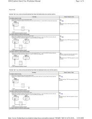
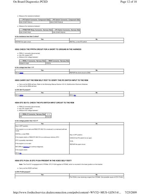
Measure the resistance between:<br />
( + ) IFS Switch Connector, Component Side ( - ) IFS Switch Connector, Component Side<br />
IGN START/RUN-A<br />
IGN START/RUN-B<br />
Measure the resistance between:<br />
( + ) FPDM PWR Relay Connector, Harness Side ( - ) IFS Switch Connector, Harness Side<br />
IGN START/RUN<br />
IGN START/RUN-B<br />
Is the resistance less than 5 ohms?<br />
REPAIR the open circuit.<br />
Yes<br />
INSTALL a new IFS switch.<br />
No<br />
KB52 CHECK THE FPRTN CIRCUIT FOR A SHORT TO GROUND IN THE HARNESS<br />
REM-J1 connector disconnected.<br />
Key ON, engine OFF.<br />
Measure the voltage between:<br />
( + ) REM-J1 Connector, Harness Side ( - ) REM Connector, Harness Side<br />
REM/FP PWR<br />
FPRTN<br />
Is the voltage less than 1 V?<br />
GO to KB49 .<br />
Yes<br />
REPAIR the short circuit to GND.<br />
No<br />
KB53 CARRY OUT THE REM SELF-TEST TO VERIFY THE IFS SWITCH INPUT TO THE REM<br />
Carry out the REM self-test. Refer to the Workshop Manual Section 419-10, Multifunction Electronic Modules.<br />
Carry out the REM self-test.<br />
Is DTC B2172 present?<br />
Yes<br />
GO to KB54 . GO to A1 .<br />
No<br />
KB54 DTC B2172: CHECK THE IFS SWITCH INPUT CIRCUIT TO THE REM<br />
REM-J3 connector disconnected.<br />
Key ON, engine OFF.<br />
Measure the voltage between:<br />
( + ) REM-J3 Connector, Harness Side ( - )<br />
IFS<br />
Ground<br />
Is the voltage greater than 10.5 V?<br />
Key in OFF position.<br />
Yes<br />
No<br />
If the engine is a no start and REM DTC B2172 is received in on-demand self-test<br />
mode:<br />
INSTALL a new REM.<br />
If the engine starts or REM DTC B2172 is a continuous memory DTC:<br />
DTC is possibly intermittent.<br />
If the engine is a no start:<br />
RETURN to Section 3 to continue diagnosis.<br />
Key in OFF position.<br />
CHECK the IFS switch for an open.<br />
If OK,<br />
REPAIR the open circuit.<br />
If the engine starts:<br />
GO to Z1 .<br />
KB55 DTC P1234: IS DTC P1234 PRESENT IN THE KOEO SELF-TEST?<br />
Note: The Ford GT is equipped with 2 FPDMs. DTC P1234 applies to FPDM2, which is mounted in the lower position on the bracket.<br />
Carry out the KOEO self-test.<br />
Is DTC P1234 present?<br />
Yes<br />
No<br />
The PCM is now receiving a signal from FPDM2. <strong>On</strong>e possible cause <strong>of</strong> DTC P1234