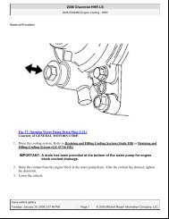
Page 1 of 4 2004 Explorer Sport Trac Workshop Manual 3/29/2009 ...
Page 1 of 4 2004 Explorer Sport Trac Workshop Manual 3/29/2009 ...
Page 1 of 4 2004 Explorer Sport Trac Workshop Manual 3/29/2009 ...

You also want an ePaper? Increase the reach of your titles
YUMPU automatically turns print PDFs into web optimized ePapers that Google loves.
<strong>2004</strong> <strong>Explorer</strong> <strong>Sport</strong> <strong>Trac</strong> <strong>Workshop</strong> <strong>Manual</strong><br />
http://www.fordtechservice.dealerconnection.com/pubs/content/~WS4R/~MUS~LEN/20/S...<br />
<strong>Page</strong> 1 <strong>of</strong> 4<br />
3/<strong>29</strong>/<strong>2009</strong><br />
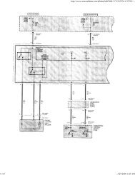
Pinpoint Tests<br />
PINPOINT TEST E: ALL DOOR LOCKS ARE INOPERATIVE FROM THE DRIVER DOOR LOCK CONTROL SWITCH<br />
Test Step<br />
E1 CHECK CIRCUIT 57 (BK)<br />
Disconnect: Driver Door Lock Control Switch C505.<br />
Measure the resistance between driver door lock control switch C505 pin 4, circuit 57 (BK), harness side and ground.<br />
Yes<br />
GO to E2.<br />
Result / Action to Take<br />
No<br />
REPAIR the circuit. TEST the system for normal<br />
operation.<br />
<br />
Is the resistance less than 5 ohms?<br />
E2 CHECK CIRCUIT 120 (PK/LG) FOR AN OPEN<br />
Disconnect: Passenger Door Lock Control Switch C605.<br />
Measure the resistance between driver door lock control switch C505 pin 3, circuit 120 (PK/LG), harness side and<br />
passenger door lock control switch C605 pin 3, circuit 120 (PK/LG), harness side.<br />
Yes<br />
GO to E3.<br />
No<br />
REPAIR the circuit. TEST the system for normal<br />
operation.<br />
<br />
Is the resistance less than 5 ohms?<br />
E3 CHECK CIRCUIT 119 (PK/YE) FOR AN OPEN<br />
Measure the resistance between driver door lock control switch C505 pin 7, circuit 119 (PK/YE), harness side and<br />
passenger door lock control switch C605 pin 7, circuit 119 (PK/YE), harness side.<br />
Yes<br />
INSTALL a new driver door lock control switch.<br />
TEST the system for normal operation.<br />
No<br />
REPAIR the circuit. TEST the system for normal<br />
operation.<br />
<br />
Is the resistance less than 5 ohms?<br />
PINPOINT TEST F: ALL DOOR LOCKS ARE INOPERATIVE FROM THE PASSENGER DOOR LOCK CONTROL SWITCH<br />
F1 CHECK CIRCUIT 57 (BK)<br />
Test Step<br />
Disconnect: Passenger Door Lock Control Switch C605.<br />
Measure the resistance between passenger door lock control switch C605 pin 4, circuit 57 (BK), harness side and<br />
ground.<br />
Yes<br />
GO to F2.<br />
Result / Action to Take<br />
No<br />
REPAIR the circuit. TEST the system for normal<br />
operation.<br />
<br />
Is the resistance less than 5 ohms?<br />
F2 CHECK CIRCUIT 120 (PK/LG) FOR AN OPEN<br />
Disconnect: Driver Door Lock Control Switch C505.<br />
Measure the resistance between driver door lock control switch C505 pin 3, circuit 120 (PK/LG), harness side and<br />
passenger door lock control switch C605 pin 3, circuit 120 (PK/LG), harness side.<br />
Yes<br />
GO to F3.<br />
No<br />
REPAIR the circuit. TEST the system for normal<br />
operation.<br />
<br />
Is the resistance less than 5 ohms?<br />
F3 CHECK CIRCUIT 119 (PK/YE) FOR AN OPEN
<strong>2004</strong> <strong>Explorer</strong> <strong>Sport</strong> <strong>Trac</strong> <strong>Workshop</strong> <strong>Manual</strong><br />
http://www.fordtechservice.dealerconnection.com/pubs/content/~WS4R/~MUS~LEN/20/S...<br />
<strong>Page</strong> 2 <strong>of</strong> 4<br />
3/<strong>29</strong>/<strong>2009</strong><br />
Measure the resistance between driver door lock control switch C505 pin 7, circuit 119 (PK/YE), harness side and<br />
passenger door lock control switch C605 pin 7, circuit 119 (PK/YE), harness side.<br />
Yes<br />
INSTALL a new passenger door lock control<br />
switch. TEST the system for normal operation.<br />
No<br />
REPAIR the circuit. TEST the system for normal<br />
operation.<br />
<br />
Is the resistance less than 5 ohms?<br />
PINPOINT TEST G: ALL DOOR LOCKS ARE INOPERATIVE<br />
Test Step<br />
G1 CHECK THE DIAGNOSTIC TROUBLE CODES (DTCS)<br />
Use the recorded vehicle security module DTCs from the continuous and on-demand self-test.<br />
Was DTC B1309 or B1341 retrieved?<br />
Result / Action to Take<br />
Yes<br />
If B1309 was retrieved, GO to G2 .<br />
G2 CHECK CIRCUIT 119 (PK/YE)<br />
Disconnect the battery. Refer to Section 414-01.<br />
Disconnect: Vehicle Security Module C274b.<br />
Measure the resistance between vehicle security module C274b pin 17, circuit 119 (PK/YE), harness<br />
side and ground.<br />
If B1341 was retrieved, GO to G5 .<br />
No<br />
GO to G8.<br />
Yes<br />
GO to G14.<br />
No<br />
GO to G3.<br />
<br />
Is the resistance greater than 10,000 ohms?<br />
G3 CHECK THE DRIVER DOOR LOCK CONTROL SWITCH<br />
Disconnect: Driver Door Lock Control Switch C505.<br />
Measure the resistance between vehicle security module C274b pin 17, circuit 119 (PK/YE), harness<br />
side and ground.<br />
Yes<br />
INSTALL a new driver door lock control switch. CLEAR the DTCs.<br />
REPEAT the self-test.<br />
No<br />
GO to G4.<br />
<br />
Is the resistance greater than 10,000 ohms?<br />
G4 CHECK THE PASSENGER DOOR LOCK CONTROL SWITCH<br />
Disconnect: Passenger Door Lock Control Switch C605.<br />
Measure the resistance between vehicle security module C274b pin 17, circuit 119 (PK/YE), harness<br />
side and ground.<br />
Yes<br />
INSTALL a new passenger door lock control switch. CLEAR the<br />
DTCs. REPEAT the self-test.<br />
No<br />
GO to G5.<br />
<br />
Is the resistance greater than 10,000 ohms?<br />
G5 CHECK CIRCUIT 120 (PK/LG)<br />
Disconnect the battery. Refer to Section 414-01.<br />
Disconnect: Vehicle Security Module C274b.<br />
Measure the resistance between vehicle security module C274b pin 9, circuit 120 (PK/LG), harness<br />
side and ground.<br />
Yes<br />
GO to G14.<br />
No<br />
GO to G6.
<strong>2004</strong> <strong>Explorer</strong> <strong>Sport</strong> <strong>Trac</strong> <strong>Workshop</strong> <strong>Manual</strong><br />
http://www.fordtechservice.dealerconnection.com/pubs/content/~WS4R/~MUS~LEN/20/S...<br />
<strong>Page</strong> 3 <strong>of</strong> 4<br />
3/<strong>29</strong>/<strong>2009</strong><br />
<br />
Is the resistance greater than 10,000 ohms?<br />
G6 CHECK THE DRIVER LOCK SWITCH<br />
Disconnect: Driver Door Lock Control Switch C505.<br />
Measure the resistance between vehicle security module C274b pin 9, circuit 120 (PK/LG), harness<br />
side and ground.<br />
Yes<br />
INSTALL a new driver door lock control switch. CLEAR the DTCs.<br />
REPEAT the self-test.<br />
No<br />
GO to G7.<br />
<br />
Is the resistance greater than 10,000 ohms?<br />
G7 CHECK THE PASSENGER LOCK SWITCH<br />
Disconnect: Passenger Door Lock Control Switch C605.<br />
Measure the resistance between vehicle security module C274b pin 9, circuit 120 (PK/LG), harness<br />
side and ground.<br />
Yes<br />
INSTALL a new passenger door lock control switch. CLEAR the<br />
DTCs. REPEAT the self-test.<br />
No<br />
GO to G8.<br />
<br />
Is the resistance greater than 10,000 ohms?<br />
G8 CHECK CIRCUIT 117 (PK/BK) FOR A SHORT TO GROUND<br />
Disconnect the battery. Refer to Section 414-01.<br />
Disconnect: Vehicle Security Module C274b.<br />
Measure the resistance between vehicle security module C274b pin 22, circuit 117 (PK/BK), harness<br />
side and ground.<br />
Yes<br />
GO to G9.<br />
No<br />
REPAIR the circuit. TEST the system for normal operation.<br />
<br />
Is the resistance greater than 10,000 ohms?<br />
G9 CHECK CIRCUIT 118 (PK/OG) FOR A SHORT TO GROUND<br />
<br />
Measure the resistance between vehicle security module C274b pin 11, circuit 118 (PK/OG), harness<br />
side and ground.<br />
Yes<br />
GO to G10.<br />
No<br />
REPAIR the circuit. TEST the system for normal operation.<br />
<br />
Is the resistance greater than 10,000 ohms?<br />
G10 CHECK CIRCUIT 163 (RD/OG) FOR A SHORT TO GROUND<br />
Disconnect: Vehicle Security Module C274a.<br />
Measure the resistance between vehicle security module C274a pin 1, circuit 163 (RD/OG), harness<br />
side and ground.<br />
Yes<br />
GO to G11.<br />
No<br />
REPAIR the circuit. TEST the system for normal operation.
<strong>2004</strong> <strong>Explorer</strong> <strong>Sport</strong> <strong>Trac</strong> <strong>Workshop</strong> <strong>Manual</strong><br />
http://www.fordtechservice.dealerconnection.com/pubs/content/~WS4R/~MUS~LEN/20/S...<br />
<strong>Page</strong> 4 <strong>of</strong> 4<br />
3/<strong>29</strong>/<strong>2009</strong><br />
<br />
Is the resistance greater than 10,000 ohms?<br />
G11 CHECK CIRCUIT 117 (PK/BK) FOR AN OPEN<br />
Disconnect the following connectors:<br />
passenger door lock actuator C603<br />
driver door lock actuator C525<br />
driver rear door lock actuator C704<br />
passenger rear door lock actuator C804<br />
Measure the resistance between vehicle security module C274b pin 22, circuit 117 (PK/BK), harness<br />
side and all door lock actuators, circuit 117 (PK/BK), harness side.<br />
Yes<br />
GO to G12.<br />
No<br />
REPAIR the circuit. TEST the system for normal operation.<br />
<br />
Are the resistances less than 5 ohms?<br />
G12 CHECK CIRCUIT 118 (PK/OG) FOR AN OPEN<br />
Measure the resistance between the vehicle security module C274b pin 11, circuit 118 (PK/OG),<br />
harness side and passenger door lock actuators, circuit 118 (PK/OG), harness side.<br />
Yes<br />
GO to G13.<br />
No<br />
REPAIR the circuit. TEST the system for normal operation.<br />
<br />
Are the resistances less than 5 ohms?<br />
G13 CHECK CIRCUIT 163 (RD/OG) FOR AN OPEN<br />
Measure the resistance between vehicle security module C274a pin 1, circuit 163 (RD/OG), harness<br />
side and driver door lock actuator C525, circuit 163 (RD/OG), harness side.<br />
Yes<br />
GO to G14.<br />
No<br />
REPAIR the circuit. TEST the system for normal operation.<br />
Are the resistances less than 5 ohms?<br />
G14 CHECK THE VEHICLE SECURITY MODULE FOR CORRECT OPERATION<br />
Disconnect all vehicle security module connectors.<br />
Check for:<br />
corrosion<br />
pushed-out pins<br />
Connect all vehicle security module connectors and make sure they seat correctly.<br />
Reconnect the battery. Refer to Section 414-01.<br />
Operate the system and verify the concern is still present.<br />
Is the concern still present?<br />
Yes<br />
INSTALL a new vehicle security module. REFER to Section 419-10.<br />
CLEAR the DTCs. REPEAT the self-test.<br />
No<br />
The system is operating correctly at this time. Concern may have<br />
been caused by a loose or corroded connector. CLEAR the DTCs.<br />
REPEAT the self-test.