Druckschrift 99811574, Professional Broadcast Antennas - Kathrein
Druckschrift 99811574, Professional Broadcast Antennas - Kathrein
Druckschrift 99811574, Professional Broadcast Antennas - Kathrein

Create successful ePaper yourself
Turn your PDF publications into a flip-book with our unique Google optimized e-Paper software.
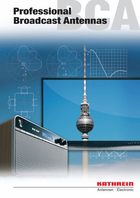
BCA<br />
<strong>Professional</strong><br />
<strong>Broadcast</strong> <strong>Antennas</strong>
Catalogue Issue 07/2011<br />
<strong>Kathrein</strong> Plant IV near Rosenheim, Germany
<strong>Kathrein</strong> <strong>Broadcast</strong> <strong>Antennas</strong><br />
<strong>Kathrein</strong> is one of the world’s leading manufacturers of professional broadcast<br />
antenna systems, including a full range of transmitting antennas for FM, TV, DAB and<br />
DVB broadcasting.<br />
KATHREIN-Werke KG was founded in 1919 in Rosenheim, Germany, to produce antennas<br />
and lightning protection equipment.<br />
Since 1955 <strong>Kathrein</strong> has been supplying professional antenna systems of all sizes to<br />
broadcasters in every part of the world, from Canada to China and from Norway to South<br />
Africa.<br />
Right from the start <strong>Kathrein</strong> has maintained a high level of engineering capability.<br />
Today there is a team of antenna and mechanical engineers dealing exclusively with<br />
broadcast transmitting antennas.<br />
This highly qualified engineering team is responsible for:<br />
– Design of components (antennas, power splitters, etc.).<br />
– Design and optimization of complete antenna systems.<br />
– Installation and testing of antenna systems.<br />
– Project management.<br />
<strong>Kathrein</strong> can provide turn-key installations in cooperation with other contractors or using<br />
the customer’s installation personnel.<br />
Customers are welcome to take advantage of the technical expertise available from<br />
<strong>Kathrein</strong> and to discuss their specific requirements. If your needs cannot be met with our<br />
standard components we are prepared to develop special solutions for you.<br />
<strong>Kathrein</strong>’s quality management system is certified in accordance with ISO 9001, which<br />
includes not only all manufacturing operations, but also design processes.<br />
“Quality leads the way”<br />
As the world’s oldest and largest antenna manufacturer, we live up to claim “Quality leads the way” on a<br />
daily basis. One of the fundamental principies is to always be on the lookout for the best solution for our<br />
customers.<br />
Our quality assurance system and our environmental management system apply to the entire company<br />
and are certified by TÜV according to EN ISO 9001 and EN ISO 14001.<br />
3
Please note:<br />
As a result of more stringent legal regulations and judgements regarding product<br />
liability, we are obliged to point out certain risks that may arise when products are<br />
used under extraordinary operating conditions.<br />
The mechanical design is based on the environmental conditions as stipulated in<br />
ETS 300 019-1-4, which include the static mechanical load imposed on an antenna by wind<br />
at maximum velocity.<br />
Extraordinary operating conditions, such as heavy icing or exceptional dynamic stress<br />
(e.g. strain caused by oscillating support structures), may result in the breakage of an<br />
antenna or even cause it to fall to the ground.<br />
Cylindrical bodies can show crosswind response, which can cause the supporting structure<br />
to oscillate and to be damaged (see EN 1991-1-4 or EN 1993-3-1).<br />
Prismatic bodies, even with non-circular cross-section can show crosswind response, which<br />
can cause the supporting structure to oscillate (see EN 191-1-4 or EN 1993-3-1).<br />
These facts must be considered during the site planning process.<br />
The maximum wind velocities listed should be understood in the sense of working values<br />
according to DIN and EN standards. These values include a safety factor below the ultimate<br />
limit state (elastic limit or permanent deformation). For these wind velocities we guarantee<br />
the mechanical safety and the electrical integrity of our antennas.<br />
4
Band I (VHF) Antenna Systems<br />
47 ... 88 MHz<br />
Band I (VHF) <strong>Antennas</strong><br />
47 ... 88 MHz<br />
Antenna Systems<br />
The antenna systems listed are<br />
examples of typical confi gurations.<br />
The mechanical and electrical data<br />
can be used to estimate gain, size<br />
and mechanical loads of a system.<br />
The fi nal confi guration and technical<br />
data of an individually designed<br />
antenna system, meeting the<br />
customer’s specifi c needs, will be<br />
determined by the <strong>Kathrein</strong> engineers.<br />
<strong>Antennas</strong>, Power Splitters and<br />
Accessories<br />
The basic antennas and related<br />
components shown in this catalog are<br />
only a small portion of the <strong>Kathrein</strong><br />
broadcast product line.<br />
Many special versions are available,<br />
with different connectors, higher power<br />
ratings, and other features such as<br />
special probes or extra ice protection.<br />
Your enquiries are most welcome and<br />
we would like to discuss your special<br />
requirements.<br />
Band II (FM) Antenna Systems<br />
87.5 – 108 MHz<br />
Band II (FM) <strong>Antennas</strong><br />
87.5 – 108 MHz<br />
Band III (VHF) Antenna Systems<br />
174 – 230 MHz<br />
Band III (VHF) <strong>Antennas</strong><br />
174 – 230 MHz<br />
Band IV/V (UHF) Antenna Systems<br />
470 – 862 MHz<br />
Band IV/V (UHF) <strong>Antennas</strong><br />
470 – 862 MHz<br />
L Band Antenna Systems<br />
1452 – 1492 MHz<br />
Power Splitters<br />
Futher Components<br />
Technical Annex
Summary of Types<br />
The articles are listed by type number in numerical order.<br />
Type No. Page Type No. Page Type No. Page Type No. Page Type No. Page<br />
600 ...<br />
600 849 131<br />
601 787 102<br />
715 ...<br />
750 10031 101<br />
600 204 51<br />
600 850 131<br />
601 819 16<br />
715 022 97<br />
750 10032 101<br />
600 223 18<br />
600 851 131<br />
601 820 16<br />
715 849 40<br />
750 10033 76<br />
600 225 18<br />
600 869 131<br />
601 821 16<br />
750 10034 47<br />
600 227 18<br />
600 870 131<br />
601 822 18<br />
734 ...<br />
750 10035 47<br />
600 232 52<br />
600 871 131<br />
601 823 18<br />
734 360 112<br />
750 10060 108<br />
600 234 79<br />
600 874 131<br />
601 824 18<br />
734 361 112<br />
750 10062 108<br />
600 241 68<br />
600 875 131<br />
601 835 72<br />
734 362 112<br />
750 10063 108<br />
600 256 73<br />
600 890 77<br />
601 939 71<br />
734 363 112<br />
750 10066 106<br />
600 261 69<br />
600 891 77<br />
601 940 69<br />
734 364 112<br />
750 10067 106<br />
600 263 50<br />
600 892 77<br />
601 966 97<br />
734 365 112<br />
750 10068 106<br />
600 265 75<br />
600 991 131<br />
601 979 43<br />
750 10069 106<br />
600 267 75<br />
736 ...<br />
750 10082 99<br />
600 479 132<br />
601 ...<br />
736 801 120<br />
750 10083 99<br />
600 480 132<br />
601 070 16<br />
602 ...<br />
736 802 120<br />
750 10085 74<br />
600 481 130<br />
601 071 16<br />
602 036 68<br />
736 803 120<br />
600 482 130<br />
601 072 16<br />
602 037 17<br />
736 804 120<br />
750 101..<br />
600 483 130<br />
601 157 72<br />
602 038 17<br />
736 805 120<br />
750 10112 108<br />
600 484 130<br />
601 278 40<br />
602 039 17<br />
750 10113 108<br />
600 504 130<br />
601 417 97<br />
602 040 17<br />
750 ...<br />
750 10114 108<br />
600 505 130<br />
601 584 103<br />
602 041 17<br />
750 807 68<br />
750 10115 108<br />
600 821 130<br />
601 629 40<br />
602 042 17<br />
750 10116 108<br />
600 843 131<br />
601 647 132<br />
602 052 132<br />
750 100..<br />
750 10117 108<br />
600 844 131<br />
601 694 41<br />
602 232 72<br />
750 10008 41<br />
750 10118 108<br />
600 845 131<br />
601 695 103<br />
602 371 99<br />
750 10012 101<br />
750 10120 110<br />
600 846 131<br />
601 699 71<br />
750 10013 101<br />
750 10122 110<br />
600 847 131<br />
601 709 99<br />
710 ...<br />
750 10016 101<br />
750 10124 110<br />
600 848 131<br />
601 768 43<br />
710 747 69<br />
750 10017 101<br />
750 10125 110<br />
6
Summary of Types<br />
The articles are listed by type number in numerical order.<br />
Type No. Page Type No. Page Type No. Page Type No. Page Type No. Page<br />
750 10128 112<br />
750 103..<br />
759 13851 114<br />
765 817 119<br />
768 344 120<br />
750 10130 111<br />
750 10315 101<br />
759 14152 116<br />
765 818 119<br />
768 345 120<br />
750 10131 111<br />
750 10350 70<br />
765 819 119<br />
768 494 76<br />
750 10132 111<br />
750 10351 70<br />
762 ...<br />
765 820 119<br />
750 10161 80<br />
762 109 44<br />
765 821 119<br />
769 ...<br />
750 10175 101<br />
751 ...<br />
762 943 46<br />
765 822 119<br />
769 731 99<br />
750 10180 107<br />
751 10215 121<br />
765 823 119<br />
750 10192 102<br />
751 10216 121<br />
763 ...<br />
765 824 119<br />
770 ...<br />
751 10217 121<br />
763 715 46<br />
765 825 119<br />
770 144 119<br />
750 102..<br />
751 10281 120<br />
765 826 119<br />
770 145 119<br />
750 10225 44<br />
751 10282 120<br />
764 ...<br />
765 827 119<br />
770 146 119<br />
750 10226 44<br />
751 10283 120<br />
764 485 119<br />
765 828 119<br />
770 147 119<br />
750 10240 78<br />
764 486 119<br />
765 829 119<br />
770 148 119<br />
750 10242 78<br />
752 ...<br />
764 487 119<br />
770 149 119<br />
750 10245 81<br />
752 183 41<br />
764 488 119<br />
767 ...<br />
770 510 119<br />
750 10246 81<br />
764 489 119<br />
767 006 106<br />
770 511 119<br />
750 10247 81<br />
754 ...<br />
764 491 119<br />
770 512 119<br />
750 10266 45<br />
754 154 44<br />
764 493 119<br />
768 ...<br />
770 513 119<br />
750 10267 45<br />
764 494 119<br />
768 331 120<br />
770 514 119<br />
750 10270 104<br />
755 ...<br />
764 495 119<br />
768 332 120<br />
770 515 119<br />
750 10271 104<br />
755 587 44<br />
764 496 119<br />
768 333 120<br />
770 516 119<br />
750 10272 104<br />
764 497 119<br />
768 334 120<br />
770 517 119<br />
750 10290 82<br />
757 ...<br />
764 499 119<br />
768 335 120<br />
770 518 119<br />
750 10291 82<br />
757 629 44<br />
768 336 120<br />
770 519 119<br />
750 10292 82<br />
765 ...<br />
768 340 120<br />
770 520 119<br />
750 10295 83<br />
759 ...<br />
765 814 119<br />
768 341 120<br />
770 521 119<br />
750 10296 83<br />
759 044 132<br />
765 815 119<br />
768 342 120<br />
770 776 48<br />
750 10297 83<br />
759 13232 115<br />
765 816 119<br />
768 343 120<br />
770 777 48<br />
7
Summary of Types<br />
The articles are listed by type number in numerical order.<br />
Type No. Page Type No. Page Type No. Page Type No. Page Type No. Page<br />
772 ...<br />
775 738 49<br />
K 52 31 57 73<br />
K 61 ...<br />
K 72 ...<br />
772 500 42<br />
775 838 49<br />
K 52 31 81 7 16<br />
K 61 12 0 132<br />
K 72 23 41 103<br />
772 501 42<br />
K 52 31 82 7 16<br />
K 61 13 0 132<br />
K 72 23 47 103<br />
772 502 42<br />
776 ...<br />
K 52 31 83 7 16<br />
K 61 14 01 130<br />
K 72 31 47 97<br />
772 549 101<br />
776 165 99<br />
K 52 31 84 7 16<br />
K 61 14 02 130<br />
K 72 36 47 102<br />
772 550 101<br />
776 166 99<br />
K 52 31 85 7 16<br />
K 61 14 03 130<br />
772 999 101<br />
776 167 99<br />
K 52 31 86 7 16<br />
K 61 14 04 130<br />
K 73 ...<br />
776 168 99<br />
K 52 33 57 69<br />
K 61 14 05 130<br />
K 73 31 47 99<br />
773 ...<br />
776 202 99<br />
K 52 33 58 69<br />
K 61 15 11 131<br />
773 000 101<br />
776 203 99<br />
K 52 34 17 41<br />
K 61 15 12 131<br />
773 332 101<br />
K 52 34 517 72<br />
K 61 15 13 131<br />
773 333 101<br />
K 52 ...<br />
K 52 34 527 72<br />
K 61 15 21 131<br />
773 361 80<br />
K 52 14 17 51<br />
K 52 34 528 72<br />
K 61 15 22 131<br />
K 52 16 81 7 18<br />
K 52 34 81 7 17<br />
K 61 15 23 131<br />
774 ...<br />
K 52 16 82 7 18<br />
K 52 34 82 7 17<br />
K 61 15 31 131<br />
774 038 97<br />
K 52 16 83 7 18<br />
K 52 34 83 7 17<br />
K 61 15 32 131<br />
774 039 97<br />
K 52 16 84 7 18<br />
K 52 34 84 7 17<br />
K 61 15 33 131<br />
774 040 97<br />
K 52 16 85 7 18<br />
K 52 34 85 7 17<br />
K 61 15 41 131<br />
774 041 97<br />
K 52 16 86 7 18<br />
K 52 34 86 7 17<br />
K 61 15 42 131<br />
774 046 97<br />
K 52 17 517 77<br />
K 52 40 17 50<br />
K 61 15 43 131<br />
774 047 97<br />
K 52 17 527 77<br />
K 52 40 517 75<br />
K 61 15 52 131<br />
774 052 97<br />
K 52 17 537 77<br />
K 52 40 527 75<br />
K 61 15 61 131<br />
K 52 22 17 52<br />
K 61 15 62 131<br />
775 ...<br />
K 52 22 57 79<br />
K 53 ...<br />
K 61 16 01 132<br />
775 000 53<br />
K 52 30 57 68<br />
K 53 32 187 43<br />
K 61 16 02 132<br />
775 001 53<br />
K 52 30 58 68<br />
K 53 32 188 43<br />
K 61 30 1 130<br />
775 002 53<br />
K 52 31 187 40<br />
K 53 33 57 71<br />
K 61 30 2 130<br />
775 130 46<br />
K 52 31 188 40<br />
K 53 33 58 71<br />
8
Systems<br />
47... 88 MHz<br />
Antenna Systems<br />
47 ... 88 MHz<br />
9
TV Transmitting Antenna<br />
Polarization<br />
47…88 MHz<br />
H<br />
l Antenna array of straight dipole panels (page 16) for different radiation patterns, especially<br />
suitable for mounting on square masts.<br />
Input<br />
Max. power<br />
Frequency<br />
VSWR<br />
Impedance<br />
Polarization<br />
Internal connections<br />
Vertical radiation pattern<br />
Horizontal radiation pattern<br />
Half antenna splitting<br />
Pressurization<br />
Painting<br />
Grounding<br />
Max. wind velocity<br />
Connectors according to IEC, EIA or DIN.<br />
According to customer’s requirements.<br />
One channel in Band I (47 … 88 MHz)<br />
s < 1.05 in one channel<br />
50 Ω<br />
Horizontal<br />
Connectors according to IEC, EIA or DIN<br />
are used throughout the system,<br />
allowing easy assembly and maintenance.<br />
Null fill and beam tilt upon request.<br />
Omnidirectional, directional or custom-designed.<br />
Upon request, the antenna can be divided into<br />
2 halves (for measurement and maintenance).<br />
The 2 halves are connected by a<br />
2-way power splitter or patch panel.<br />
Splitters and connecting cables can be supplied<br />
with dry air (please specify when ordering).<br />
If required, the antenna is painted in aviation<br />
warning colours.<br />
Via mounting parts.<br />
225 km/h<br />
H<br />
S<br />
No. of Panels Gain* Weight in kg (without mounting hardware) Windload in kN (160 km/h) Antenna height H in m (Spacing S in m)<br />
bays per in Frequency in MHz Frequency in MHz Frequency in MHz<br />
bay dBd 47–54 54–61 60–68 66–72 76–82 82–88 47–54 54–61 60–68 66–72 76–82 82–88 47–54 54–61 60–68 66–72 76–82 82–88<br />
2 1) 3 1) 4 1) 2 1) 3 1) 4 1) 2 1) 3 1) 4 1)<br />
2 2) 3 2) 4 2) 5 2) 6 2) 2 2) 3 2) 4 2) 5 2) 6 2) 2 2) 3 2) 4 2) 5 2) 6 2)<br />
2 5.4 280 250 220 200 190 180 3.7 3.3 2.9 2.7 2.4 2.2<br />
1 3 3.5 450 400 350 320 300 300 6.2 5.4 4.8 4.4 3.9 3.7 4.5 4.0 3.6 3.3 2.9 2.7<br />
4 2.0 620 540 460 440 420 400 7.4 6.5 5.8 5.3 4.7 4.4<br />
2 8.4 620 540 460 440 420 400 7.4 6.5 5.8 5.3 4.7 4.4<br />
2 3 6.6 950 840 750 700 660 630 12.4 10.9 9.7 8.9 7.8 7.3 10.9 9.6 8.6 8.0 7.0 6.5<br />
4 5.0 1250 1100 970 900 850 800 14.9 13.0 11.6 10.7 9.4 8.8 (6.4) (5.6) (5.0) (4.7) (4.1) (3.8)<br />
2 11.5 1250 1100 970 900 850 800 14.9 13.0 11.6 10.7 9.4 8.8<br />
4 3 9.6 1750 1550 1480 1360 1300 1250 24.9 21.8 19.3 17.8 15.7 14.7 23.7 20.8 18.6 17.4 15.2 14.1<br />
4 8.1 2500 2200 1960 1800 1710 1630 29.7 26.0 23.1 21.3 18.8 17.6 (6.4) (5.6) (5.0) (4.7) (4.1) (3.8)<br />
2 13.3 1750 1550 1480 1360 1300 1250 22.3 19.5 17.3 16.0 14.1 13.2<br />
6 3 11.4 2770 2450 2200 2000 1900 1820 37.3 32.6 29.0 26.6 23.5 22.0 36.5 32.0 28.6 26.7 23.3 21.7<br />
4 9.9 3700 3260 2920 2700 2550 2420 44.6 39.0 34.7 32.0 28.2 26.4 (6.4) (5.6) (5.0) (4.7) (4.1) (3.8)<br />
2 14.5 2500 2200 1960 1800 1710 1630 29.7 26.0 23.1 21.3 18.8 17.6<br />
8 3 12.6 3700 3260 2920 2700 2550 2420 49.7 43.5 38.6 35.5 31.3 29.3 49.3 43.2 38.6 36.1 31.5 29.3<br />
4 11.1 4920 4350 3900 3560 3370 3200 59.4 52.0 46.2 42.6 37.6 35.2 (6.4) (5.6) (5.0) (4.7) (4.1) (3.8)<br />
* Attenuation of the internal cabling and the gain-decrease in case of null fill in the<br />
vertical radiation pattern are not considered.<br />
Approximate values for gain decrease:<br />
cable attenuation: 0.2 – 0.5 dB<br />
null fill:<br />
0.3 – 1.0 dB<br />
Gain figures are valid for the direction of maximum radiation (see diagrams on<br />
following page).<br />
10<br />
1)<br />
System B, Europa<br />
2)<br />
System M, N, America
TV Transmitting Antenna<br />
Polarization<br />
47…88 MHz<br />
H<br />
Systems<br />
47... 88 MHz<br />
Horizontal Radiation Patterns<br />
Examples of typical horizontal<br />
antenna arrays and their horizontal radiation patterns<br />
for minimal mast dimensions.<br />
Vertical Radiation Patterns<br />
Examples of typical vertical<br />
radiation patterns*) for several bays<br />
of identical, vertically stacked<br />
antenna arrays.<br />
Equal power splitting<br />
1,0<br />
2 bays<br />
E rel<br />
30 40<br />
0,5<br />
0 10 20 α°<br />
1,0<br />
4 bays<br />
10<br />
10<br />
3<br />
dB<br />
3<br />
dB<br />
E rel<br />
30 40<br />
0,5<br />
0 10 20 α°<br />
0<br />
0<br />
Equal power splitting<br />
Different power splitting<br />
4/10 P<br />
1,0<br />
6 bays<br />
E rel<br />
30 40<br />
1/10 P<br />
0,5<br />
1/10 P<br />
4/10 P<br />
0 10 20 α°<br />
1,0<br />
8 bays<br />
0,5<br />
10<br />
10<br />
3<br />
dB<br />
3<br />
dB<br />
E rel<br />
30 40<br />
0 10 20 α°<br />
0<br />
0<br />
*) without null fill<br />
with null fill and beam tilt<br />
11
TV Transmitting Antenna<br />
Polarization<br />
47…88 MHz<br />
H<br />
l Antenna array of bent dipole panels (page 17) for different radiation patterns, especially<br />
suitable for mounting on triangular or round masts.<br />
Input<br />
Max. power<br />
Frequency<br />
VSWR<br />
Impedance<br />
Polarization<br />
Internal connections<br />
Vertical radiation pattern<br />
Horizontal radiation pattern<br />
Half antenna splitting<br />
Pressurization<br />
Painting<br />
Grounding<br />
Max. wind velocity<br />
Connectors according to IEC, EIA or DIN.<br />
According to customer’s requirements.<br />
One channel in Band I (47 … 88 MHz)<br />
s < 1.05 in one channel<br />
50 Ω<br />
Horizontal<br />
Connectors according to IEC, EIA or DIN<br />
are used throughout the system,<br />
allowing easy assembly and maintenance.<br />
Null fill and beam tilt upon request.<br />
Omnidirectional, directional or custom-designed.<br />
Upon request, the antenna can be divided into<br />
2 halves (for measurement and maintenance).<br />
The 2 halves are connected by a<br />
2-way power splitter or patch panel.<br />
Splitters and connecting cables can be supplied<br />
with dry air (please specify when ordering).<br />
If required, the antenna is painted in aviation<br />
warning colours.<br />
Via mounting parts.<br />
225 km/h<br />
H<br />
S<br />
No. of Panels Gain* Weight in kg (without mounting hardware) Windload in kN (160 km/h) Antenna height H in m (Spacing S in m)<br />
bays per in Frequency in MHz Frequency in MHz Frequency in MHz<br />
bay dBd 47–54 54–61 60–68 66–72 76–82 82–88 47–54 54–61 60–68 66–72 76–82 82–88 47–54 54–61 60–68 66–72 76–82 82–88<br />
2 1) 3 1) 4 1) 2 1) 3 1) 4 1) 2 1) 3 1) 4 1)<br />
1<br />
2<br />
4<br />
6<br />
8<br />
2 2) 3 2) 4 2) 5 2) 6 2) 2 2) 3 2) 4 2) 5 2) 6 2) 2 2) 3 2) 4 2) 5 2) 6 2)<br />
2 3.9 310 275 250 235 205 195 4.1 3.3 2.9 2.7 2.4 2.2 4.5 4.0 3.6 3.3 2.9 2.7<br />
3 1.7 470 410 375 350 310 290 5.6 4.9 4.4 4.1 3.6 2.9<br />
2 6.9 650 550 500 470 410 390 8.1 6.5 5.8 5.3 4.7 4.4 10.9 9.6 8.6 8.0 7.0 6.5<br />
3 4.7 990 820 750 700 620 580 11.3 9.9 8.9 8.2 7.1 5.9 (6.4) (5.6) (5.0) (4.7) (4.1) (3.8)<br />
2 9.9 1310 1095 1000 935 825 775 16.3 13.0 11.6 10.7 9.4 8.8 23.7 20.8 18.6 17.4 15.2 14.1<br />
3 7.7 1910 1645 1500 1405 1235 1165 22.5 19.8 17.8 16.3 14.3 11.8 (6.4) (5.6) (5.0) (4.7) (4.1) (3.8)<br />
2 11.7 1910 1645 1500 1405 1235 1165 24.4 19.5 17.3 16.0 14.1 13.2 36.5 32.0 28.6 26.7 23.3 21.7<br />
3 9.5 2820 2645 2250 2105 1855 1745 33.8 29.6 26.6 24.5 21.4 17.7 (6.4) (5.6) (5.0) (4.7) (4.1) (3.8)<br />
2 12.9 2600 2190 2000 1870 1650 1550 32.5 26.0 23.1 21.3 18.8 17.6 49.3 43.2 38.6 36.1 31.5 29.3<br />
3 10.7 3800 3290 3000 2810 2470 2330 45.0 39.5 35.5 32.6 28.5 23.5 (6.4) (5.6) (5.0) (4.7) (4.1) (3.8)<br />
* Attenuation of the internal cabling and the gain-decrease in case of null fill in the<br />
vertical radiation pattern are not considered.<br />
Approximate values for gain decrease:<br />
cable attenuation: 0.2 – 0.5 dB<br />
null fill:<br />
0.3 – 1.0 dB<br />
Gain figures are valid for the direction of maximum radiation (see diagrams on<br />
following page).<br />
1)<br />
System B, Europa<br />
2)<br />
System M, N, America<br />
12
TV Transmitting Antenna<br />
Polarization<br />
47…88 MHz<br />
H<br />
Systems<br />
47... 88 MHz<br />
Horizontal Radiation Patterns<br />
Examples of typical horizontal<br />
antenna arrays and their horizontal radiation patterns<br />
for minimal mast dimensions.<br />
Vertical Radiation Patterns<br />
Examples of typical vertical<br />
radiation patterns*) for several bays<br />
of identical, vertically stacked<br />
antenna arrays.<br />
Equal power splitting<br />
1,0<br />
2 bays<br />
E rel<br />
30 40<br />
0,5<br />
60°<br />
0 10 20 α°<br />
1,0<br />
4 bays<br />
10<br />
10<br />
3<br />
dB<br />
3<br />
dB<br />
E rel<br />
30 40<br />
0,5<br />
0 10 20 α°<br />
0<br />
0<br />
Different power splitting<br />
3/4 P<br />
3/7 P<br />
1,0<br />
6 bays<br />
E rel<br />
30 40<br />
60°<br />
0,5<br />
1/7 P<br />
0 10 20 α°<br />
1/4 P<br />
3/7 P<br />
1,0<br />
8 bays<br />
0,5<br />
10<br />
10<br />
3<br />
dB<br />
3<br />
dB<br />
E rel<br />
30 40<br />
0 10 20 α°<br />
0<br />
0<br />
*) without null fill<br />
with null fill and beam tilt<br />
13
<strong>Antennas</strong> for TV in lower VHF Band<br />
47 ... 88 MHz<br />
<strong>Antennas</strong><br />
47... 88 MHz<br />
15
Panel Antenna<br />
Polarization<br />
47…88 MHz<br />
H<br />
l Especially suitable for square and round masts.<br />
Radiation Patterns<br />
(at mid-band)<br />
72°<br />
10<br />
3<br />
dB<br />
0<br />
Horizontal Radiation Pattern<br />
56°<br />
10<br />
Length see table<br />
3<br />
0<br />
dB<br />
Vertical Radiation Pattern<br />
Order No. 601 070 601 071 601 072 601 819 601 820 601 821<br />
K 52 31 81 7 K 52 31 82 7 K 52 31 83 7 K 52 31 84 7 K 52 31 85 7 K 52 31 86 7<br />
Input<br />
Max. power<br />
Frequency<br />
Channel System B, Europa<br />
System M, N, America<br />
VSWR<br />
Gain (at mid-band)<br />
Impedance<br />
Polarization<br />
Weight<br />
Wind load in kN (at 160 km/h)<br />
frontal<br />
lateral<br />
Max. wind velocity<br />
Dimensions in mm<br />
A<br />
B<br />
C<br />
Material:<br />
Mounting:<br />
Grounding:<br />
Scope of supply:<br />
Special features:<br />
Ice protection:<br />
Combinations:<br />
7-16 female<br />
6 kW (higher power upon request)<br />
47 – 54 MHz 54 – 61 MHz 60 – 68 MHz 66 – 72 MHz 76 – 82 MHz 82 – 88 MHz<br />
2 3 4<br />
2 3 4 5 6<br />
< 1.15<br />
7.5 dBd<br />
50 Ω<br />
Horizontal<br />
140 kg 124 kg 110 kg 100 kg 94 kg 89 kg<br />
2.50 2.20 1.95 1.80 1.60 1.50<br />
1.25 1.10 0.95 0.90 0.80 0.75<br />
225 km/h<br />
3360 2960 2640 2470 2165 2015<br />
3200 2800 2500 2340 2040 1900<br />
1330 1180 1060 995 875 820<br />
Hot-dip galvanized steel. Radome: Fiberglass.<br />
Mounting hardware and mounting dimensions upon request.<br />
Via mounting parts.<br />
Antenna consisting of two half-wave dipoles with reflector screens.<br />
The antenna is shipped dismounted.<br />
Even under severe icy conditions the antenna is still functional due to its heavy-duty<br />
construction and the fiberglass covers for the feeding points.<br />
The antenna is especially suitable as a component in arrays to achieve various radiation<br />
patterns. Particularly for square and round masts.<br />
16
Panel Antenna<br />
Polarization<br />
47…88 MHz<br />
H<br />
l Especially suitable for triangular and round masts.<br />
Radiation Patterns<br />
(at mid-band)<br />
<strong>Antennas</strong><br />
47... 88 MHz<br />
80°<br />
10<br />
3<br />
dB<br />
0<br />
Horizontal Radiation Pattern<br />
56°<br />
10<br />
3<br />
dB<br />
Length see table<br />
0<br />
Vertical Radiation Pattern<br />
Order No. 602 037 602 038 602 039 602 040 602 041 602 042<br />
K 52 34 81 7 K 52 34 82 7 K 52 34 83 7 K 52 34 84 7 K 52 34 85 7 K 52 34 86 7<br />
Input<br />
Max. power<br />
Frequency<br />
Channel System B, Europa<br />
System M, N, America<br />
VSWR<br />
Gain (at mid-band)<br />
Impedance<br />
Polarization<br />
Weight<br />
Wind load in kN (at 160 km/h)<br />
frontal<br />
lateral<br />
Max. wind velocity<br />
Dimensions in mm<br />
A<br />
B<br />
C<br />
Material:<br />
Mounting:<br />
Grounding:<br />
Scope of supply:<br />
Special features:<br />
Ice protection:<br />
Combinations:<br />
7-16 female<br />
6 kW (higher power on request)<br />
47 – 54 MHz 54 – 61 MHz 60 – 68 MHz 66 – 72 MHz 76 – 82 MHz 82 – 88 MHz<br />
2 3 4<br />
2 3 4 5 6<br />
< 1.15<br />
7 dBd<br />
50 Ω<br />
Horizontal<br />
148 kg 137 kg 125 kg 117 kg 103 kg 97 kg<br />
2.50 2.20 2.00 1.85 1.60 1.45<br />
1.30 1.20 1.10 1.00 0.90 0.85<br />
225 km/h<br />
3360 2960 2640 2470 2165 2015<br />
3200 2800 2500 2340 2040 1900<br />
1330 1180 1060 995 875 820<br />
Hot-dip galvanized steel. Radome: Fiberglass.<br />
Mounting hardware and mounting dimensions upon request.<br />
Via mounting parts.<br />
Antenna consisting of two half-wave dipoles with reflector screens.<br />
The antenna is shipped dismounted.<br />
Even under icy conditions the antenna keeps operating due to the radomes covering the feed<br />
areas.<br />
The antenna is especially suitable as a component in arrays to achieve various radiation<br />
patterns. Particularly for triangular and round masts.<br />
17
Yagi Antenna<br />
Polarization<br />
47…88 MHz<br />
H<br />
V<br />
l 8 element Yagi-antenna of weather-proof aluminum, fiberglass-elements<br />
with encapsulated copper stranded wire.<br />
Radiation Patterns<br />
(at mid-band)<br />
68°<br />
10<br />
3<br />
dB<br />
0<br />
C<br />
in E-plane<br />
Horizontal Radiation Pattern<br />
128°<br />
A<br />
Length see table<br />
B<br />
10<br />
3<br />
dB<br />
0<br />
in H-plane<br />
Vertical Radiation Pattern<br />
Order No. 600 223 600 225 600 227 601 822 601 823 601 824<br />
K 52 16 81 7 K 52 16 82 7 K 52 16 83 7 K 52 16 84 7 K 52 16 85 7 K 52 16 86 7<br />
Input<br />
Max. power<br />
Frequency<br />
Channel System B, Europa<br />
System M, N, America<br />
VSWR<br />
Gain (at mid-band)<br />
Impedance<br />
Polarization<br />
Weight<br />
Wind load in N (at 160 km/h)<br />
Horizontally polarized frontal<br />
lateral<br />
Vertically polarized frontal<br />
lateral<br />
Max. wind velocity<br />
Dimensions in mm<br />
A<br />
B<br />
C<br />
Material:<br />
Mounting:<br />
Grounding:<br />
Special features:<br />
Combinations:<br />
7-16 female<br />
500 W<br />
47 – 54 MHz 54 – 61 MHz 60 – 68 MHz 66 – 72 MHz 76 – 82 MHz 82 – 88 MHz<br />
2 3 4<br />
2 3 4 5 6<br />
< 1.15<br />
6 dBd<br />
50 Ω<br />
Horizontal or vertical by conversion of the clamps<br />
18 kg 15 kg 12.5 kg 11.5 kg 10 kg 9 kg<br />
715 615 540 500 440 400<br />
675 575 475 440 375 350<br />
715 615 540 500 440 400<br />
790 675 615 565 500 465<br />
160 km/h<br />
3500 2950 2700 2420 2120 1970<br />
3000 2510 2240 2070 1810 1680<br />
2225 1950 1740 1610 1410 1310<br />
Support: Weather-proof aluminum. Elements: Fiberglass with inlaid copper wire.<br />
Cover: Fiberglass. Clamp: Hot-dip galvanized steel.<br />
To pipes of 60 – 115 mm diameter by means of mounting clamps, supplied.<br />
Via mounting parts.<br />
The antenna is shipped dismounted.<br />
Two or more antennas can be combined to achieve higher gain and longer, narrower<br />
beam width.<br />
18
Antenna Systems<br />
87.5 – 108 MHz<br />
Systems<br />
87.5 – 108 MHz<br />
19
FM Transmitting Antenna<br />
Polarization<br />
87.5–108 MHz<br />
H<br />
l Antenna array of dipole panels (page 40) for different radiation patterns.<br />
l Especially suitable for mounting on square masts.<br />
l The feeder network is made up of coaxial power splitters and flexible connecting cables in<br />
accordance with the radiation patterns specification and the transmitting power.<br />
Input<br />
Max. power<br />
Frequency<br />
VSWR<br />
Impedance<br />
Polarization<br />
Internal connections<br />
Vertical radiation pattern<br />
Horizontal radiation pattern<br />
Half antenna splitting<br />
Pressurization<br />
Painting<br />
Grounding<br />
Max. wind velocity<br />
Connectors according to IEC, EIA or DIN.<br />
According to customer’s requirements.<br />
87.5 – 108 MHz<br />
s < 1.2 throughout the whole frequency range.<br />
Lower VSWR for single channels upon request.<br />
50 Ω<br />
Horizontal<br />
Connectors according to IEC, EIA or DIN<br />
are used throughout the system,<br />
allowing easy assembly and maintenance.<br />
Null fill and beam tilt upon request.<br />
Omnidirectional, directional or custom-designed.<br />
Upon request, the antenna can be divided into<br />
2 halves (for measurement and maintenance).<br />
The 2 halves are connected by a<br />
2-way power splitter or patch panel.<br />
Splitters and connecting cables can be supplied<br />
with dry air (please specify when ordering).<br />
If required, the antenna is painted in aviation<br />
warning colours.<br />
Via mounting parts.<br />
225 km/h<br />
H<br />
3200 mm<br />
No. Panels Gain* Weight Antenna Windload<br />
ofper (at mid-band) (without mounting height H (v = 160 km/h)<br />
bays bay dBd times hardware) kg m kN<br />
2 5.0 3.2 140 2.4<br />
1 3 3.5 2.2 200 2.5 3.9<br />
4 2.0 1.6 260 4.9<br />
2 8.0 6.3 260 4.9<br />
2 3 6.5 4.5 400 5.7 7.9<br />
4 5.0 3.2 530 9.8<br />
2 11.0 12.6 530 9.8<br />
4 3 9.5 8.9 790 12.1 15.8<br />
4 8.0 6.3 1080 19.5<br />
2 12.8 19.1 790 14.6<br />
6 3 11.3 13.0 1200 18.5 23.6<br />
4 9.7 9.3 1610 29.3<br />
2 14.0 25.1 1080 19.5<br />
8 3 12.5 17.8 1610 24.9 31.5<br />
4 11.0 12.6 2150 39.0<br />
* Attenuation of the internal cabling and the gain-decrease in case of null fill in the<br />
vertical radiation pattern are not considered.<br />
Approximate values for gain decrease:<br />
cable attenuation: 0.2 – 0.5 dB<br />
null fill:<br />
0.3 – 1.0 dB<br />
Gain figures are valid for the direction of maximum radiation (see diagrams on<br />
following page).<br />
20
FM Transmitting Antenna<br />
Polarization<br />
87.5–108 MHz<br />
H<br />
Horizontal Radiation Patterns<br />
Vertical Radiation Patterns<br />
Examples of typical horizontal<br />
antenna arrays and their horizontal radiation patterns<br />
for minimal mast dimensions.<br />
Examples of typical vertical<br />
radiation patterns*) for several bays<br />
of identical, vertically stacked<br />
antenna arrays.<br />
Systems<br />
87.5 – 108 MHz<br />
Equal power splitting<br />
1,0<br />
2 bays<br />
E rel<br />
30 40<br />
0,5<br />
0 10 20 α°<br />
1,0<br />
4 bays<br />
10<br />
10<br />
3<br />
dB<br />
3<br />
dB<br />
E rel<br />
30 40<br />
0,5<br />
0 10 20 α°<br />
0<br />
0<br />
Equal power splitting<br />
Different power splitting<br />
4/10 P<br />
1,0<br />
6 bays<br />
E rel<br />
30 40<br />
1/10 P<br />
0,5<br />
4/10 P<br />
0 10 20 α°<br />
1/10 P<br />
1,0<br />
8 bays<br />
E rel<br />
30 40<br />
0,5<br />
10<br />
10<br />
3<br />
0<br />
dB<br />
3<br />
0<br />
dB<br />
0 10 20 α°<br />
*) without null fill<br />
with null fill and beam tilt<br />
21
FM Transmitting Antenna<br />
Polarization<br />
87.5–108 MHz<br />
V<br />
l Antenna array of dipole panels (page 40) for different radiation patterns.<br />
l Especially suitable for mounting on square masts.<br />
l The feeder network is made up of coaxial power splitters and flexible connecting cables in<br />
accordance with the radiation patterns specification and the transmitting power.<br />
Input<br />
Max. power<br />
Frequency<br />
VSWR<br />
Impedance<br />
Polarization<br />
Internal connections<br />
Vertical radiation pattern<br />
Horizontal radiation pattern<br />
Half antenna splitting<br />
Pressurization<br />
Painting<br />
Grounding<br />
Max. wind velocity<br />
Connectors according to IEC, EIA or DIN.<br />
According to customer’s requirements.<br />
87.5 – 108 MHz<br />
s < 1.2 throughout the whole frequency range.<br />
Lower VSWR for single channels upon request.<br />
50 Ω<br />
Vertical<br />
Connectors according to IEC, EIA or DIN<br />
are used throughout the system,<br />
allowing easy assembly and maintenance.<br />
Null fill and beam tilt upon request.<br />
Omnidirectional, directional or custom-designed.<br />
Upon request, the antenna can be divided into<br />
2 halves (for measurement and maintenance).<br />
The 2 halves are connected by a<br />
2-way power splitter or patch panel.<br />
Splitters and connecting cables can be supplied<br />
with dry air (please specify when ordering).<br />
If required, the antenna is painted in aviation<br />
warning colours.<br />
Via mounting parts.<br />
225 km/h<br />
H<br />
3000 mm<br />
No. Panels Gain* Weight Antenna Windload<br />
ofper (at mid-band) (without mounting height H (v = 160 km/h)<br />
bays bay dBd times hardware) kg m kN<br />
2 5.4 3.5 140 2.3<br />
1 3 3.7 2.3 200 1.8 3.8<br />
4 2.3 1.7 260 4.7<br />
2 8.4 6.9 260 4.7<br />
2 3 6.7 4.7 400 4.8 7.7<br />
4 5.3 3.4 530 9.3<br />
2 11.4 13.8 530 9.3<br />
4 3 9.7 9.3 790 10.8 15.3<br />
4 8.3 6.8 1080 18.6<br />
2 13.2 20.9 790 14.0<br />
6 3 11.5 14.1 1200 16.8 23.0<br />
4 10.1 10.2 1610 27.9<br />
2 14.4 27.5 1080 18.6<br />
8 3 12.7 18.6 1610 25.8 30.6<br />
4 11.3 13.5 2150 37.2<br />
* Attenuation of the internal cabling and the gain-decrease in case of null fill in the<br />
vertical radiation pattern are not considered.<br />
Approximate values for gain decrease:<br />
cable attenuation: 0.2 – 0.5 dB<br />
null fill:<br />
0.3 – 1.0 dB<br />
Gain figures are valid for the direction of maximum radiation (see diagrams on<br />
following page).<br />
22
dB<br />
dB<br />
dB<br />
dB<br />
FM Transmitting Antenna<br />
Polarization<br />
87.5–108 MHz<br />
V<br />
Horizontal Radiation Patterns<br />
Vertical Radiation Patterns<br />
Examples of typical horizontal<br />
antenna arrays and their horizontal radiation patterns<br />
for minimal mast dimensions.<br />
Examples of typical vertical<br />
radiation patterns*) for several bays<br />
of identical, vertically stacked<br />
antenna arrays.<br />
Systems<br />
87.5 – 108 MHz<br />
Equal power splitting<br />
1,0<br />
2 bays<br />
E rel<br />
30 40<br />
0,5<br />
0 10 20 α°<br />
1,0<br />
4 bays<br />
10<br />
10<br />
3<br />
3<br />
E rel<br />
30 40<br />
0,5<br />
0 10 20 α°<br />
0<br />
0<br />
Equal power splitting<br />
Different power splitting<br />
4/10 P<br />
1,0<br />
6 bays<br />
E rel<br />
30 40<br />
1/10 P<br />
0,5<br />
4/10 P<br />
0 10 20 α°<br />
1/10 P<br />
1,0<br />
8 bays<br />
E rel<br />
30 40<br />
0,5<br />
10<br />
10<br />
3<br />
0<br />
3<br />
0<br />
0 10 20 α°<br />
*) without null fill<br />
with null fill and beam tilt<br />
23
FM Transmitting Antenna<br />
Polarization<br />
87.5–108 MHz<br />
H<br />
l Antenna array of dipole panels (page 41) for different radiation patterns.<br />
l Especially suitable for mounting on triangular or round masts.<br />
l The feeder network is made up of coaxial power splitters and flexible connecting cables in<br />
accordance with the radiation patterns specification and the transmitting power.<br />
Input<br />
Max. power<br />
Frequency<br />
VSWR<br />
Impedance<br />
Polarization<br />
Internal connections<br />
Vertical radiation pattern<br />
Horizontal radiation pattern<br />
Half antenna splitting<br />
Pressurization<br />
Painting<br />
Grounding<br />
Max. wind velocity<br />
Connectors according to IEC, EIA or DIN.<br />
According to customer’s requirements.<br />
87.5 – 108 MHz<br />
s < 1.2 throughout the whole frequency range.<br />
Lower VSWR for single channels upon request.<br />
50 Ω<br />
Horizontal<br />
Connectors according to IEC, EIA or DIN<br />
are used throughout the system,<br />
allowing easy assembly and maintenance.<br />
Null fill and beam tilt upon request.<br />
Omnidirectional, directional or custom-designed.<br />
Upon request, the antenna can be divided into<br />
2 halves (for measurement and maintenance).<br />
The 2 halves are connected by a<br />
2-way power splitter or patch panel.<br />
Splitters and connecting cables can be supplied<br />
with dry air (please specify when ordering).<br />
If required, the antenna is painted in aviation<br />
warning colours.<br />
Via mounting parts.<br />
225 km/h<br />
H<br />
3200 mm<br />
No. Panels Gain* Weight Antenna Windload<br />
ofper (at mid-band) (without mounting height H (v = 160 km/h)<br />
bays bay dBd times hardware) kg m kN<br />
1<br />
2<br />
4<br />
6<br />
8<br />
2 3.9 2.5 150 2.9<br />
3 1.7 1.5 220<br />
2.5<br />
4.4<br />
2 6.9 4.9 290 5.9<br />
3 4.7 3.0 420<br />
5.7<br />
8.8<br />
2 9.9 9.8 560 11.8<br />
3 7.7 5.9 850<br />
12.1<br />
17.5<br />
2 11.7 14.8 850 17.6<br />
3 9.5 8.9 1290<br />
18.5<br />
26.3<br />
2 12.9 19.5 1150 23.5<br />
3 10.7 11.7 1700<br />
24.9<br />
35.0<br />
* Attenuation of the internal cabling and the gain-decrease in case of null fill in the<br />
vertical radiation pattern are not considered.<br />
Approximate values for gain decrease:<br />
cable attenuation: 0.2 – 0.5 dB<br />
null fill:<br />
0.3 – 1.0 dB<br />
Gain figures are valid for the direction of maximum radiation (see diagrams on<br />
following page).<br />
24
FM Transmitting Antenna<br />
Polarization<br />
87.5–108 MHz<br />
H<br />
Horizontal Radiation Patterns<br />
Vertical Radiation Patterns<br />
Examples of typical horizontal<br />
antenna arrays and their horizontal radiation patterns<br />
for minimal mast dimensions.<br />
Examples of typical vertical<br />
radiation patterns*) for several bays<br />
of identical, vertically stacked<br />
antenna arrays.<br />
Systems<br />
87.5 – 108 MHz<br />
Equal power splitting<br />
1,0<br />
2 bays<br />
E rel<br />
30 40<br />
0,5<br />
60°<br />
0 10 20 α°<br />
1,0<br />
4 bays<br />
10<br />
10<br />
3<br />
dB<br />
3<br />
dB<br />
E rel<br />
30 40<br />
0,5<br />
0 10 20 α°<br />
0<br />
0<br />
Different power splitting<br />
3/4 P<br />
3/7 P<br />
1,0<br />
6 bays<br />
60°<br />
0,5<br />
1/7 P<br />
E rel<br />
30 40<br />
0 10 20 α°<br />
1/4 P<br />
3/7 P<br />
1,0<br />
8 bays<br />
E rel<br />
30 40<br />
0,5<br />
10<br />
10<br />
3<br />
0<br />
dB<br />
3<br />
0<br />
dB<br />
0 10 20 α°<br />
*) without null fill<br />
with null fill and beam tilt<br />
25
FM Transmitting Antenna<br />
Polarization<br />
87.5–108 MHz<br />
V<br />
l Antenna array of dipole panels (page 42) for different radiation patterns.<br />
l Especially suitable for mounting on triangular or round masts.<br />
l The feeder network is made up of coaxial power splitters and flexible connecting cables in<br />
accordance with the radiation patterns specification and the transmitting power.<br />
Input<br />
Max. power<br />
Frequency<br />
VSWR<br />
Impedance<br />
Polarization<br />
Internal connections<br />
Vertical radiation pattern<br />
Horizontal radiation pattern<br />
Half antenna splitting<br />
Pressurization<br />
Painting<br />
Grounding<br />
Max. wind velocity<br />
Connectors according to IEC, EIA or DIN.<br />
According to customer’s requirements.<br />
87.5 – 108 MHz<br />
s < 1.2 throughout the whole frequency range.<br />
Lower VSWR for single channels upon request.<br />
50 Ω<br />
Vertical<br />
Connectors according to IEC, EIA or DIN<br />
are used throughout the system,<br />
allowing easy assembly and maintenance.<br />
Null fill and beam tilt upon request.<br />
Omnidirectional, directional or custom-designed.<br />
Upon request, the antenna can be divided into<br />
2 halves (for measurement and maintenance).<br />
The 2 halves are connected by a<br />
2-way power splitter or patch panel.<br />
Splitters and connecting cables can be supplied<br />
with dry air (please specify when ordering).<br />
If required, the antenna is painted in aviation<br />
warning colours.<br />
Via mounting parts.<br />
225 km/h<br />
H<br />
3000 mm<br />
No. Panels Gain* Weight Antenna Windload<br />
ofper (at mid-band) (without mounting height H (v = 160 km/h)<br />
bays bay dBd times hardware) kg m kN<br />
1<br />
2<br />
4<br />
6<br />
8<br />
2 3.9 2.5 150 2.4<br />
3 1.7 1.5 220<br />
2.2<br />
3.9<br />
2 6.9 4.9 290 4.8<br />
3 4.7 3.0 420<br />
5.2<br />
7.7<br />
2 9.9 9.8 560 9.6<br />
3 7.7 5.9 850<br />
11.2<br />
15.5<br />
2 11.7 14.8 850 14.3<br />
3 9.5 8.9 1290<br />
17.2<br />
23.2<br />
2 12.9 19.5 1150 19.1<br />
3 10.7 11.7 1700<br />
23.2<br />
30.9<br />
* Attenuation of the internal cabling and the gain-decrease in case of null fill in the<br />
vertical radiation pattern are not considered.<br />
Approximate values for gain decrease:<br />
cable attenuation: 0.2 – 0.5 dB<br />
null fill:<br />
0.3 – 1.0 dB<br />
Gain figures are valid for the direction of maximum radiation (see diagrams on<br />
following page).<br />
26
dB<br />
dB<br />
dB<br />
dB<br />
FM Transmitting Antenna<br />
Polarization<br />
87.5–108 MHz<br />
V<br />
Horizontal Radiation Patterns<br />
Vertical Radiation Patterns<br />
Examples of typical horizontal<br />
antenna arrays and their horizontal radiation patterns<br />
for minimal mast dimensions.<br />
Examples of typical vertical<br />
radiation patterns*) for several bays<br />
of identical, vertically stacked<br />
antenna arrays.<br />
Systems<br />
87.5 – 108 MHz<br />
Equal power splitting<br />
1,0<br />
2 bays<br />
E rel<br />
30 40<br />
0,5<br />
60°<br />
0 10 20 α°<br />
1,0<br />
4 bays<br />
E rel<br />
30 40<br />
0,5<br />
10<br />
10<br />
3<br />
0<br />
3<br />
0<br />
0 10 20 α°<br />
Different power splitting<br />
3/4 P<br />
3/7 P<br />
1,0<br />
6 bays<br />
E rel<br />
30 40<br />
60°<br />
0,5<br />
1/7 P<br />
1/4 P<br />
3/7 P<br />
0 10 20 α°<br />
1,0<br />
8 bays<br />
E rel<br />
30 40<br />
0,5<br />
10<br />
10<br />
3<br />
0<br />
3<br />
0<br />
0 10 20 α°<br />
*) without null fill<br />
with null fill and beam tilt<br />
27
FM Transmitting Antenna<br />
Polarization<br />
87.5–108 MHz<br />
H V X<br />
l Antenna array of circularly polarized dipole panels (page 43) for different radiation patterns.<br />
l Especially suitable for mounting on square masts.<br />
l The feeder network is made up of coaxial power splitters and flexible connecting cables<br />
in accordance with the radiation patterns specification and the transmitting power.<br />
Input<br />
Max. power<br />
Frequency<br />
VSWR<br />
Impedance<br />
Polarization<br />
Internal connections<br />
Vertical radiation pattern<br />
Horizontal radiation pattern<br />
Half antenna splitting<br />
Pressurization<br />
Painting<br />
Grounding<br />
Max. wind velocity<br />
Connectors according to IEC, EIA or DIN.<br />
According to customer’s requirements.<br />
87.5 – 108 MHz<br />
s < 1.2 throughout the whole frequency range.<br />
Lower VSWR for single channels upon request.<br />
50 Ω<br />
Linear, circular or elliptical<br />
Connectors according to IEC, EIA or DIN<br />
are used throughout the system,<br />
allowing easy assembly and maintenance.<br />
Null fill and beam tilt upon request.<br />
Omnidirectional, directional or custom-designed.<br />
Upon request, the antenna can be divided into<br />
2 halves (for measurement and maintenance).<br />
The 2 halves are connected by a<br />
2-way power splitter or patch panel.<br />
Splitters and connecting cables can be supplied<br />
with dry air (please specify when ordering).<br />
If required, the antenna is painted in aviation<br />
warning colours.<br />
Via mounting parts.<br />
225 km/h<br />
H<br />
3000 mm<br />
No. Panels Gain* Weight Antenna Windload<br />
ofper (at mid-band) (without mounting height H (v = 160 km/h)<br />
bays bay dBd times hardware) kg m kN<br />
2 2.0 1.6 200 2.7<br />
1 3 0.5 1.1 320 2.2 4.3<br />
4 –1.0 0.8 420 5.4<br />
2 5.0 3.2 420 5.4<br />
2 3 3.5 2.4 750 5.2 8.5<br />
4 2.0 1.6 850 10.8<br />
2 8.0 6.3 850 10.8<br />
4 3 6.5 4.5 1530 11.2 17.0<br />
4 5.0 3.2 1660 21.5<br />
2 9.8 9.6 1530 16.1<br />
6 3 8.3 6.8 1870 17.2 25.5<br />
4 6.7 4.7 2240 32.3<br />
2 11.0 12.6 1660 21.5<br />
8 3 9.5 8.9 2240 23.2 34.0<br />
4 8.0 6.3 2970 43.0<br />
* Attenuation of the internal cabling and the gain-decrease in case of null fill in the<br />
vertical radiation pattern are not considered.<br />
Approximate values for gain decrease:<br />
cable attenuation: 0.2 – 0.5 dB<br />
null fill:<br />
0.3 – 1.0 dB<br />
Gain figures are valid for the direction of maximum radiation (see diagrams on<br />
following page).<br />
28
FM Transmitting Antenna<br />
Polarization<br />
87.5–108 MHz<br />
H V X<br />
Horizontal Radiation Patterns<br />
Vertical Radiation Patterns<br />
Examples of typical horizontal<br />
antenna arrays and their horizontal radiation patterns<br />
for minimal mast dimensions.<br />
Examples of typical vertical<br />
radiation patterns*) for several bays<br />
of identical, vertically stacked<br />
antenna arrays.<br />
Systems<br />
87.5 – 108 MHz<br />
Equal power splitting<br />
1,0<br />
2 bays<br />
E rel<br />
30 40<br />
0,5<br />
0 10 20 α°<br />
1,0<br />
4 bays<br />
10<br />
10<br />
3<br />
dB<br />
3<br />
dB<br />
E rel<br />
30 40<br />
0,5<br />
0 10 20 α°<br />
0<br />
0<br />
Equal power splitting<br />
Different power splitting<br />
4/10 P<br />
1,0<br />
6 bays<br />
4/10 P<br />
E rel<br />
30 40<br />
0,5<br />
1/10 P<br />
1/10 P<br />
0 10 20 α°<br />
1,0<br />
8 bays<br />
E rel<br />
30 40<br />
0,5<br />
10<br />
10<br />
3<br />
0<br />
dB<br />
3<br />
0<br />
dB<br />
0 10 20 α°<br />
*) without null fill<br />
with null fill and beam tilt<br />
29
FM Transmitting Antenna<br />
Polarization<br />
87.5–108 MHz<br />
X<br />
l Antenna array of circularly polarized dipole panels (page 44) for different radiation patterns.<br />
l Especially suitable for mounting on triangular or round masts.<br />
l The feeder network is made up of coaxial power splitters and flexible connecting cables<br />
in accordance with the radiation patterns specification and the transmitting power.<br />
Input<br />
Max. power<br />
Frequency<br />
VSWR<br />
Impedance<br />
Polarization<br />
Internal connections<br />
Vertical radiation pattern<br />
Horizontal radiation pattern<br />
Half antenna splitting<br />
Pressurization<br />
Painting<br />
Grounding<br />
Max. wind velocity<br />
Connectors according to IEC, EIA or DIN.<br />
According to customer’s requirements.<br />
87.5 – 108 MHz<br />
s < 1.2 throughout the whole frequency range.<br />
Lower VSWR for single channels upon request.<br />
50 Ω<br />
Circular<br />
Connectors according to IEC, EIA or DIN<br />
are used throughout the system,<br />
allowing easy assembly and maintenance.<br />
Null fill and beam tilt upon request.<br />
Omnidirectional, directional or custom-designed.<br />
Upon request, the antenna can be divided into<br />
2 halves (for measurement and maintenance).<br />
The 2 halves are connected by a<br />
2-way power splitter or patch panel.<br />
Splitters and connecting cables can be supplied<br />
with dry air (please specify when ordering).<br />
If required, the antenna is painted in aviation<br />
warning colours.<br />
Via mounting parts.<br />
225 km/h<br />
H<br />
3000 mm<br />
No. Panels Gain* Weight Antenna Windload<br />
ofper (at mid-band) (without mounting height H (v = 160 km/h)<br />
bays bay dBd times hardware) kg m kN<br />
1<br />
2<br />
4<br />
6<br />
8<br />
2 0.0 1.0 140 2.1<br />
3 –2.0 0.6 200<br />
1.82<br />
3.3<br />
2 3.1 2.0 260 4.3<br />
3 1.1 1.3 430<br />
4.82<br />
6.5<br />
2 6.2 4.2 580 8.5<br />
3 4.2 2.6 800<br />
10.82<br />
13.0<br />
2 8.1 6.5 800 12.8<br />
3 6.1 4.1 1230<br />
16.82<br />
19.5<br />
2 9.3 8.5 1100 17.0<br />
3 7.3 5.4 1590<br />
22.82<br />
26.0<br />
* Attenuation of the internal cabling and the gain-decrease in case of null fill in the<br />
vertical radiation pattern are not considered.<br />
Approximate values for gain decrease:<br />
cable attenuation: 0.2 – 0.5 dB<br />
null fill:<br />
0.3 – 1.0 dB<br />
Gain decrease of –3 dB due to circular polarization is already considered.<br />
Gain figures are valid for the direction of maximum radiation (see diagrams on<br />
following page).<br />
30
FM Transmitting Antenna<br />
Polarization<br />
87.5–108 MHz<br />
X<br />
Horizontal Radiation Patterns<br />
Vertical Radiation Patterns<br />
Examples of typical horizontal<br />
antenna arrays and their horizontal radiation patterns<br />
for minimal mast dimensions.<br />
Examples of typical vertical<br />
radiation patterns*) for several bays<br />
of identical, vertically stacked<br />
antenna arrays.<br />
Systems<br />
87.5 – 108 MHz<br />
Equal power splitting<br />
1,0<br />
2 bays<br />
E rel<br />
30 40<br />
0,5<br />
60°<br />
0 10 20 α°<br />
1,0<br />
4 bays<br />
10<br />
10<br />
3<br />
dB<br />
3<br />
dB<br />
E rel<br />
30 40<br />
0,5<br />
0 10 20 α°<br />
0<br />
0<br />
Different power splitting<br />
3/4 P<br />
3/7 P<br />
1,0<br />
6 bays<br />
60°<br />
0,5<br />
1/4 P<br />
1/7 P<br />
3/7 P<br />
E rel<br />
30 40<br />
0 10 20 α°<br />
1,0<br />
8 bays<br />
E rel<br />
30 40<br />
0,5<br />
10<br />
10<br />
3<br />
0<br />
dB<br />
3<br />
0<br />
dB<br />
0 10 20 α°<br />
*) without null fill<br />
with null fill and beam tilt<br />
31
FM Transmitting Antenna<br />
Polarization<br />
87.5–108 MHz<br />
X<br />
l Antenna array of elliptically polarized dipole panels (page 45) for different radiation patterns<br />
l Especially suitable for mounting on pipes.<br />
l The feeder network is made up of coaxial power splitters and flexible connecting cables<br />
in accordance with the radiation patterns specification and the transmitting power.<br />
Input<br />
Max. power<br />
Frequency<br />
VSWR<br />
Impedance<br />
Polarization<br />
Internal connections<br />
Vertical radiation pattern<br />
Horizontal radiation pattern<br />
Half antenna splitting<br />
Pressurization<br />
Painting<br />
Grounding<br />
Max. wind velocity<br />
Connectors according to IEC, EIA or DIN.<br />
According to customer’s requirements.<br />
87.5 – 108 MHz<br />
s < 1.25 throughout the whole frequency range.<br />
Lower VSWR for single channels upon request.<br />
50 Ω<br />
Elliptical<br />
Connectors according to IEC or EIA<br />
are used throughout the system,<br />
allowing easy assembly and maintenance.<br />
Null fill and beam tilt upon request.<br />
Omnidirectional,with preferred direction.<br />
Upon request, the antenna can be divided into<br />
2 halves (for measurement and maintenance).<br />
The 2 halves are connected by a<br />
2-way power splitter or patch panel.<br />
Splitters and connecting cables can be supplied<br />
with dry air (please specify when ordering).<br />
If required, the antenna is painted in aviation<br />
warning colours.<br />
Via mounting parts.<br />
225 km/h<br />
H<br />
> 500 mm<br />
2100 mm<br />
No. Gain* Weight Antenna Windload<br />
of (at mid-band) (without mounting height H (v = 160 km/h)<br />
bays dBd times hardware) kg m frontal Nlateral N<br />
4 4.5 2.8 100 7.13 460 1460<br />
6 6.3 4.3 150 11.33 690 2190<br />
8 7.5 5.6 200 15.53 920 2920<br />
> 500 mm<br />
10 8.5 7.1 250 19.73 1150 3650<br />
12 9.3 8.5 300 23.93 1380 4380<br />
16 10.5 11.2 350 28.13 1840 5840<br />
* Attenuation of the internal cabling and the gain-decrease in case of null fill in the<br />
vertical radiation pattern are not considered.<br />
Approximate values for gain decrease:<br />
cable attenuation: 0.2 – 0.5 dB<br />
null fill:<br />
0.3 – 1.0 dB<br />
Gain figures are valid for the direction of maximum radiation (see diagrams on<br />
following page).<br />
32
dB<br />
FM Transmitting Antenna<br />
Polarization<br />
87.5–108 MHz<br />
X<br />
Typical Horizontal Radiation Pattern<br />
(at mid-band)<br />
Vertical Radiation Patterns<br />
Examples of typical vertical<br />
radiation patterns*) for several bays<br />
of identical, vertically stacked<br />
antenna arrays.<br />
Systems<br />
87.5 – 108 MHz<br />
100<br />
4 bays<br />
E rel<br />
30 40<br />
50<br />
10<br />
0 10 20 α°<br />
3<br />
0<br />
1,0<br />
6 bays<br />
E rel<br />
30 40<br />
0,5<br />
0 10 20 α°<br />
1,0<br />
8 bays<br />
E rel<br />
30 40<br />
0,5<br />
0 10 20 α°<br />
1,0<br />
10 bays<br />
E rel<br />
30 40<br />
0,5<br />
0 10 20 α°<br />
*) without null fill<br />
with null fill and beam tilt<br />
33
FM-Transmitting Antenna<br />
Polarization<br />
87.5–108 MHz<br />
V<br />
l An economic FM-transmitting antenna system can be built by stacking<br />
2 or more vertical dipoles (page 46) in front of a tubular mast (∅ 60–120 mm).<br />
l Such antenna systems provide signal coverage in all azimuth directions<br />
as shown in the horizontal radiation pattern below.<br />
Input<br />
Max. power<br />
Frequency<br />
VSWR<br />
Impedance<br />
Polarization<br />
Internal connections<br />
Vertical radiation pattern<br />
Horizontal radiation pattern<br />
Half antenna splitting<br />
Pressurization<br />
Painting<br />
Grounding<br />
Max. wind velocity<br />
Connectors according to IEC, EIA or DIN.<br />
According to customer’s requirements.<br />
87.5 – 108 MHz<br />
s < 1.3 throughout the whole frequency range.<br />
Lower VSWR for single channels upon request.<br />
50 Ω<br />
Vertical<br />
Connectors according to IEC, EIA or DIN<br />
are used throughout the system,<br />
allowing easy assembly and maintenance.<br />
Null fill and beam tilt upon request.<br />
Omnidirectional.<br />
Upon request, the antenna can be divided into<br />
2 halves (for measurement and maintenance).<br />
The 2 halves are connected by a<br />
2-way power splitter or patch panel.<br />
Splitters and connecting cables can be supplied<br />
with dry air (please specify when ordering).<br />
If required, the antenna is painted in aviation<br />
warning colours.<br />
Via mounting parts.<br />
225 km/h<br />
> 250<br />
mm<br />
H<br />
2100 mm<br />
No. Gain* Weight Antenna Windload<br />
of (at mid-band) (without mounting height H (v = 160 km/h)<br />
bays dBd times hardware) kg m frontal Nlateral N<br />
2 5.0 3.2 50 3.48 230 440<br />
4 8.0 6.3 100 7.68 460 880<br />
6 9.7 9.3 150 11.88 690 1320<br />
8 11.0 12.6 200 16.08 920 1760<br />
10 11.8 15.1 250 20.28 1150 2200<br />
12 12.7 18.6 300 24.48 1380 2640<br />
16 14.0 25.1 350 32.88 1840 3520<br />
* Attenuation of the internal cabling and the gain-decrease in case of null fill in the<br />
vertical radiation pattern are not considered.<br />
Approximate values for gain decrease:<br />
cable attenuation: 0.2 – 0.5 dB<br />
null fill:<br />
0.3 – 1.0 dB<br />
Gain figures are valid for the direction of maximum radiation (see diagrams on<br />
following page).<br />
34
FM-Transmitting Antenna<br />
Polarization<br />
87.5–108 MHz<br />
V<br />
Typical Horizontal Radiation Pattern<br />
(at mid-band beamtilt ≈1°)<br />
Vertical Radiation Patterns<br />
Examples of typical vertical<br />
radiation patterns*) for several bays<br />
of identical, vertically stacked<br />
antenna arrays.<br />
Systems<br />
87.5 – 108 MHz<br />
100<br />
4 bays<br />
E rel<br />
30 40<br />
220°<br />
50<br />
10<br />
0 10 20 α°<br />
3<br />
dB<br />
0<br />
1,0<br />
6 bays<br />
E rel<br />
30 40<br />
0,5<br />
0 10 20 α°<br />
1,0<br />
8 bays<br />
E rel<br />
30 40<br />
0,5<br />
0 10 20 α°<br />
1,0<br />
12 bays<br />
E rel<br />
30 40<br />
0,5<br />
0 10 20<br />
α°<br />
*) without null fill<br />
with null fill and beam tilt<br />
35
FM Transmitting Antenna<br />
Polarization<br />
87.5–108 MHz<br />
H<br />
l Self-supporting hot-dip galvanized steel superturnstile antenna. Up to 4 bays may be stacked.<br />
l Optionally up to 8 bays may be stacked if the superturnstile antennas are mounted inside a<br />
self-supporting fiberglass cylinder.<br />
Input<br />
Max. power<br />
Frequency<br />
VSWR<br />
Impedance<br />
Polarization<br />
Vertical radiation pattern<br />
Horizontal radiation pattern<br />
Half antenna splitting<br />
Internal connections<br />
Structure<br />
Mounting<br />
Ice protection<br />
Grounding<br />
Max. wind velocity<br />
Connectors according to IEC, EIA or DIN.<br />
According to customer’s requirements,<br />
10 kW max. per bay.<br />
87.5 – 108 MHz<br />
s < 1.2 throughout the whole frequency range.<br />
Tuning not required.<br />
50 Ω<br />
Horizontal<br />
Null fill and beam tilt upon request.<br />
Omnidirectional<br />
Upon request, the antenna can be divided into<br />
2 halves (for measurement and maintenance).<br />
The 2 halves are connected by a<br />
2-way power splitter or patch panel.<br />
The radiating elements are fed with<br />
coaxial connecting cables and hybrid couplers.<br />
Connectors according to IEC, EIA or DIN<br />
are used throughout the system,<br />
allowing easy assembly and maintenance.<br />
Superturnstile antenna on self-supporting<br />
hot dip galvanized steel structure.<br />
Up to 4 bays may be stacked.<br />
On top of existing structure by means of a flange.<br />
Under icing the fiberglass cover over<br />
the feedslots and the rugged construction keep<br />
the antenna in proper function.<br />
Via mounting parts.<br />
160 km/h<br />
H<br />
3000 mm<br />
No. Gain* Weight Antenna Windload<br />
of (at mid-band) (without cylinder) height H (without cylinder)<br />
bays dBd times kg m (160 km/h) kN<br />
1 1 1.26 275 3 3.2<br />
2 4 2.51 550 6 6.5<br />
4 7 5.00 1450 12 14.0<br />
* Attenuation of the internal cabling and the gain-decrease in case of null fill in the<br />
vertical radiation pattern are not considered.<br />
Approximate values for gain decrease:<br />
cable attenuation: 0.2 – 0.4 dB<br />
null fill:<br />
0.3 – 1.0 dB<br />
Gain figures are valid for the direction of maximum radiation (see diagrams on<br />
following page).<br />
36
FM Transmitting Antenna<br />
Polarization<br />
87.5–108 MHz<br />
H<br />
Typical Horizontal Radiation Pattern<br />
(at mid-band)<br />
Vertical Radiation Patterns<br />
Examples of typical vertical<br />
radiation patterns*) for several bays<br />
of identical, vertically stacked<br />
antenna arrays.<br />
Systems<br />
87.5 – 108 MHz<br />
100<br />
1 bay<br />
E rel<br />
30 40<br />
50<br />
10<br />
0 10 20 α°<br />
3<br />
dB<br />
0<br />
100<br />
2 bays<br />
E rel<br />
30 40<br />
50<br />
0 10 20 α°<br />
100<br />
4 bays<br />
E rel<br />
30 40<br />
50<br />
0 10 20 α°<br />
100<br />
8 bays<br />
E rel<br />
30 40<br />
50<br />
0 10 20<br />
α°<br />
*) without null fill<br />
with null fill and beam tilt<br />
37
<strong>Antennas</strong> for FM in VHF Band<br />
87.5 – 108 MHz<br />
<strong>Antennas</strong><br />
87.5 – 108 MHz<br />
39
Panel Antenna<br />
Polarization<br />
87.5–108 MHz<br />
H<br />
V<br />
l Especially suitable for square masts.<br />
Order No. 601 278 601 629 715 849<br />
K 52 31 187 K 52 31 188<br />
Input 7-16 female 7/8 EIA-flange 13-30 female<br />
Max. power 2.5 kW 4 kW 6 kW<br />
Frequency<br />
87.5 – 108 MHz<br />
VSWR < 1.15<br />
Gain (at mid-band)<br />
7.5 dBd<br />
Impedance<br />
50 Ω<br />
Polarization<br />
Horizontal or vertical<br />
Weight<br />
64 kg<br />
Wind load (at 160 km/h)<br />
Horizontally polarized<br />
frontal / lateral: 1500 N / 875 N<br />
Vertically polarized<br />
frontal / lateral: 1500 N / 825 N<br />
Max. wind velocity<br />
225 km/h<br />
Material:<br />
Mounting:<br />
Hot-dip galvanized steel.<br />
Radome: Fiberglass.<br />
Mounting hardware and mounting dimensions<br />
upon request.<br />
A: 2490 mm<br />
B: 1740 mm<br />
C: 730 mm<br />
Grounding:<br />
Via mounting parts.<br />
Scope of supply:<br />
Antenna without mounting clamps.<br />
Special features:<br />
The antenna is shipped dismounted.<br />
Ice protection:<br />
Even under severe icy conditions the antenna is<br />
still functional due to its heavy-duty construction<br />
and the fiberglass covers for the feeding points.<br />
Combinations:<br />
The antenna is especially suitable as a<br />
component in arrays to achieve various radiation<br />
patterns. Particularly for square masts.<br />
Radiation Patterns (at mid-band)<br />
73°<br />
57°<br />
10<br />
10<br />
3<br />
0<br />
dB<br />
in E-plane<br />
3<br />
0<br />
dB<br />
in H-plane<br />
40
Panel Antenna<br />
Polarization<br />
87.5–108 MHz<br />
H<br />
l Especially suitable for triangular and round masts.<br />
B<br />
Order No. 601 694 750 10008 752 183<br />
K 52 34 17<br />
Input 7-16 female 7/8 EIA-flange 13-30 female<br />
Max. power 2.5 kW 4 kW 6 kW<br />
Frequency<br />
87.5 – 108 MHz<br />
VSWR < 1.2<br />
Gain (at mid-band)<br />
7 dBd<br />
Impedance<br />
50 Ω<br />
Polarization<br />
Horizontal<br />
Weight<br />
66 kg<br />
Wind load (at 160 km/h) frontal: 1700 N<br />
lateral: 875 N<br />
Max. wind velocity<br />
225 km/h<br />
A<br />
C<br />
<strong>Antennas</strong><br />
87.5 – 108 MHz<br />
Material:<br />
Hot-dip galvanized steel.<br />
Radome: Fiberglass.<br />
Mounting:<br />
Grounding:<br />
Mounting hardware and mounting dimensions<br />
upon request.<br />
Via mounting parts.<br />
A: 2490 mm<br />
B: 1740 mm<br />
C: 760 mm<br />
Scope of supply:<br />
Antenna without mounting clamps.<br />
Special features:<br />
The antenna is shipped dismounted.<br />
Ice protection:<br />
Even under severe icy conditions the antenna is<br />
still functional due to its heavy-duty construction<br />
and the fiberglass covers for the feeding points.<br />
Combinations:<br />
The antenna is especially suitable as a<br />
component in arrays to achieve various radiation<br />
patterns. Particularly for triangular and round<br />
masts.<br />
Radiation Patterns (at mid-band)<br />
80°<br />
56°<br />
10<br />
10<br />
3<br />
0<br />
dB<br />
Horizontal Radiation Pattern<br />
3<br />
0<br />
dB<br />
Vertical Radiation Pattern<br />
41
Panel Antenna<br />
Polarization<br />
87.5–108 MHz<br />
V<br />
l Especially suitable for triangular and round masts.<br />
Order No. 772 500 772 501 772 502<br />
Input 7-16 female 7/8 1 5/8<br />
EIA-flange EIA-flange<br />
Max. power 2.5 kW 5 kW 14 kW<br />
Frequency<br />
87.5 – 108 MHz<br />
VSWR < 1.15<br />
Gain (at mid-band)<br />
6 dBd<br />
Impedance<br />
50 Ω<br />
Polarization<br />
Vertical<br />
Weight 65 kg 65 kg 75 kg<br />
Wind load frontal: 1550 N 1550 N 1620 N<br />
(at 160 km/h) lateral: 850 N 850 N 970 N<br />
Max. wind velocity<br />
225 km/h<br />
A<br />
Material:<br />
Hot-dip galvanized steel.<br />
Radome: Fiberglass.<br />
Mounting:<br />
Grounding:<br />
To a vertical pipe of ∅ 89 mm by 3 pcs. U-bolts<br />
(supplied) or to proper flanges.<br />
Mounting dimensions upon request.<br />
Via mounting parts.<br />
A: 2200 mm<br />
B: 2000 mm<br />
B<br />
Ice protection:<br />
Even under icy conditions the antenna keeps<br />
operating due to the radomes covering the feed<br />
areas.<br />
Combinations:<br />
The antenna is especially suitable as a<br />
component in arrays to achieve various radiation<br />
patterns. Particularly for triangular and round<br />
masts.<br />
Scope of supply:<br />
Antenna consisting of two half-wave dipoles with<br />
reflector screen and 3 U-bolts.<br />
Special features:<br />
The antenna is shipped dismounted.<br />
Radiation Patterns (at mid-band)<br />
67°<br />
70°<br />
10<br />
3<br />
0<br />
dB<br />
Vertical Radiation Pattern<br />
10<br />
3<br />
0<br />
dB<br />
Horizontal Radiation Pattern<br />
42
Panel Antenna<br />
Polarization<br />
87.5–108 MHz<br />
H V X<br />
l Optionally for circular, horizontal, vertical or slant polarization.<br />
l Especially suitable for square masts.<br />
B<br />
Order No. 601 768 601 979<br />
K 53 32 187 K 53 32 188<br />
Input 4 x 7-16 female 4 x 7/8 EIA-flange<br />
Max. power 2.5 kW per input 4 kW per input<br />
Frequency<br />
87.5 – 108 MHz<br />
VSWR<br />
< 1.25 (linear polarization)<br />
< 1.1 (circular polarization)<br />
Gain (at mid-band)<br />
7.5 dBd (linear polarization)<br />
4.5 dBd (circular polarization)<br />
Impedance<br />
50 Ω<br />
Polarization<br />
Horizontal, vertical, circular<br />
Weight<br />
89 kg<br />
Wind load (at 160 km/h) Frontal: 1600 N<br />
Lateral: 1130 N<br />
Max. wind velocity<br />
225 km/h<br />
A<br />
A = B: 2200 mm<br />
C: 830 mm<br />
C<br />
<strong>Antennas</strong><br />
87.5 – 108 MHz<br />
4 dipoles are arranged symmetrically in front of a reflector screen. With suitable<br />
feeding the antenna radiates circularly polarized. An isolation of 40 – 50 dB<br />
between horizontal and vertical pairs of dipoles is achieved through the spezial<br />
design. This design permits the transmission of 2 programs – horizontally and<br />
vertically polarized – independently from each other.<br />
Material:<br />
Mounting:<br />
Hot-dip galvanized steel.<br />
Weather protection: fiberglass cover.<br />
The antenna must be mounted so that<br />
the bent radiators are horizontally<br />
polarized. Mounting dimensions and<br />
mounting hardware on request.<br />
Radiation Patterns<br />
(at mid-band)<br />
Horizontal Polarization<br />
(bent dipoles)<br />
Grounding:<br />
Via mounting parts.<br />
66°<br />
62°<br />
Scope of supply:<br />
Antenna without mounting clamps.<br />
Special features:<br />
The antenna will be shipped dismounted.<br />
10<br />
10<br />
Ice protection:<br />
Even under severe icy conditions the<br />
antenna is still functional due to its<br />
heavy-duty construction and the fibre -<br />
glass covers of the feeding points.<br />
3<br />
0<br />
dB<br />
in E-plane<br />
Horizontal Radiation Pattern<br />
3<br />
0<br />
dB<br />
in H-plane<br />
Vertical Radiation Pattern<br />
Combinations:<br />
The antenna is especially suitable as a<br />
com ponent in arrays to achieve various<br />
radiation patterns. Particularly for square<br />
masts.<br />
Vertical Polarization<br />
(straight dipoles)<br />
62°<br />
64°<br />
Polarization:<br />
Suitable feeding of the horizontal and<br />
vertical dipole pairs optionally result in<br />
left or right hand circular or elliptical or<br />
slant polarization or simul taneous<br />
horizontal and vertical polarization.<br />
10<br />
3<br />
dB<br />
10<br />
3<br />
dB<br />
0<br />
in H-plane<br />
Horizontal Radiation Pattern<br />
0<br />
in E-plane<br />
Vertical Radiation Pattern<br />
43
Panel Antenna<br />
Polarization<br />
87.5–108 MHz<br />
X<br />
l Especially suitable for triangular and round masts.<br />
A<br />
Order No. normal position 754 154 750 10225 755 587<br />
rotated position 757 629 750 10226 762 109<br />
Input 2 x 7-16 2 x 7/8 2 x 13-30<br />
female EIA-flange female<br />
Max. power 2.5 kW 5 kW<br />
per input<br />
per input<br />
Frequency<br />
87.5 – 108 MHz<br />
VSWR < 1.2<br />
Gain (at mid-band)<br />
3.5 dBd<br />
Impedance<br />
50 Ω<br />
Polarization<br />
Circular<br />
Weight<br />
60 kg<br />
Wind load (at 160 km/h) frontal: 1250 N<br />
lateral: 875 N<br />
Max. wind velocity<br />
225 km/h<br />
C<br />
B<br />
Material:<br />
Hot-dip galvanized steel.<br />
Radome: Fiberglass.<br />
A = B: 1820 mm<br />
C: 900 mm<br />
Mounting:<br />
Mounting hardware and mounting dimensions<br />
upon request.<br />
Grounding:<br />
Via mounting parts.<br />
Scope of supply:<br />
Antenna without mounting clamps.<br />
Special features:<br />
The antenna is shipped dismounted.<br />
Ice protection:<br />
Even under severe icy conditions the antenna is<br />
still functional due to its heavy-duty construction<br />
and the fiberglass covers for the feeding points.<br />
Combinations:<br />
The antenna is especially suitable as a<br />
component in arrays to achieve various radiation<br />
patterns. Particularly for triangular and round<br />
masts.<br />
Radiation Patterns<br />
(at mid-band)<br />
76°<br />
10<br />
3<br />
dB<br />
0<br />
Horizontal and<br />
Vertical Radiation Pattern<br />
44
dB<br />
Dipol Antenna<br />
Polarization<br />
87.5–108 MHz<br />
X<br />
l<br />
l<br />
Omnidirectional propagation with preferred direction.<br />
Mounting to pipes.<br />
Order No. 750 10266 750 10267<br />
Input 7/8˝ EIA-flange 1 5/8˝ EIA-flange<br />
Max. power 5 kW 10 kW<br />
Frequency<br />
87.5 – 108 MHz<br />
VSWR < 1.5<br />
Gain (at mid-band)<br />
–1.5 dBd<br />
Impedance<br />
50 Ω<br />
Polarization<br />
Elliptical<br />
Weight<br />
25 kg<br />
Wind load (at 160 km/h) frontal: 115 N<br />
lateral: 365 N<br />
Max. wind velocity<br />
240 km/h<br />
A<br />
B<br />
<strong>Antennas</strong><br />
87.5 – 108 MHz<br />
Material:<br />
Hot-dip galvanized steel.<br />
Mounting:<br />
Grounding:<br />
To pipes of 75 – 125 mm ∅ by means<br />
of 2 mounting clamps, supplied.<br />
Via mounting parts.<br />
A: 1385 mm<br />
B: approx. 834 mm<br />
Ice protection:<br />
Feed point radome (optional).<br />
Horizontal Radiation Patterns (at mid-band)<br />
Polarization and Pattern<br />
depending on mast structure behind<br />
10<br />
10<br />
3<br />
dB<br />
3<br />
0<br />
Vertical Polarization<br />
0<br />
Horizontal Polarization<br />
45
Dipole Antenna<br />
Polarization<br />
87.5–108 MHz<br />
V<br />
l Omnidirectional propagation with preferred direction.<br />
l For tubular masts.<br />
Order No. 762 943 763 715 775 130<br />
Input 7-16 female 7/8 1 5/8<br />
EIA-flange EIA-flange<br />
Max. power 3 kW 5 kW 10 kW<br />
Frequency<br />
87.5 – 108 MHz<br />
VSWR s < 1.3 s < 1.25<br />
Gain (at mid-band)<br />
2 dBd<br />
Impedance<br />
50 Ω<br />
Polarization<br />
Vertical<br />
Weight 13 kg 22 kg<br />
Wind load frontal: 115 N 165 N<br />
(at 160 km/h) lateral: 220 N 340 N<br />
Max. Wind velocity 225 km/h 300 km/h<br />
A<br />
Material:<br />
Mounting:<br />
Grounding:<br />
Hot-dip galvanized steel.<br />
To pipes of 60 – 125 mm by means of<br />
2 mounting clamps, supplied.<br />
Via mounting parts.<br />
B<br />
A: 1380 mm<br />
B: 830 mm<br />
Radiation Patterns (at mid-band)<br />
220°<br />
70°<br />
10<br />
10<br />
3<br />
0<br />
dB<br />
Horizontal Radiation Pattern<br />
3<br />
0<br />
dB<br />
Vertical Radiation Pattern<br />
46
Yagi Antenna<br />
Polarization<br />
87.5–108 MHz<br />
V<br />
Order No. 750 10035 750 10034<br />
Input 7-16 female 7/8˝ EIA-flange<br />
Max. power 3 kW 5 kW<br />
Frequency<br />
87.5 – 108 MHz<br />
VSWR < 1.3<br />
Gain (at mid-band)<br />
3 dBd<br />
Impedance<br />
50 Ω<br />
Polarization<br />
Vertical<br />
Weight<br />
13 kg<br />
Wind load (at 160 km/h) frontal: 180 N<br />
lateral: 320 N<br />
Max. wind velocity<br />
225 km/h<br />
A<br />
<strong>Antennas</strong><br />
87.5 – 108 MHz<br />
Material:<br />
Mounting:<br />
Hot-dip galvanized steel.<br />
To pipes of 60 – 125 mm ∅ by means<br />
of 2 U-bolts, supplied.<br />
B<br />
Grounding:<br />
Via mounting parts.<br />
A: 1800 mm<br />
B: 870 mm<br />
Radiation Patterns (at mid-band)<br />
175°<br />
75°<br />
10<br />
10<br />
3<br />
0<br />
dB<br />
Horizontal Radiation Pattern<br />
3<br />
0<br />
dB<br />
Vertical Radiation Pattern<br />
47
Yagi Antenna<br />
Polarization<br />
87.5–108 MHz<br />
V<br />
Order No. 770 777 770 776<br />
Input 7-16 female 7/8˝ EIA-flange<br />
Max. power 3 kW 5 kW<br />
Frequency<br />
87.5 – 108 MHz<br />
VSWR < 1.3<br />
Gain (at mid-band)<br />
4 dBd<br />
Impedance<br />
50 Ω<br />
Polarization<br />
Vertical<br />
Weight<br />
13 kg<br />
Wind load (at 160 km/h) frontal: 165 N<br />
lateral: 275 N<br />
Max. wind velocity<br />
225 km/h<br />
Material:<br />
Hot-dip galvanized steel.<br />
A<br />
B<br />
Mounting:<br />
Grounding:<br />
To pipes of 60 – 125 mm ∅ by means<br />
of 2 U-bolts, supplied.<br />
Via mounting parts.<br />
A: 1822 mm<br />
B: 1300 mm<br />
Radiation Patterns (at mid-band)<br />
150°<br />
70°<br />
10<br />
10<br />
3<br />
0<br />
dB<br />
Horizontal Radiation Pattern<br />
3<br />
0<br />
dB<br />
Vertical Radiation Pattern<br />
48
Yagi Antenna<br />
Polarization<br />
87.5–108 MHz<br />
V<br />
Order No. 775 838 775 738<br />
Input 7-16 female 7/8˝ EIA-flange<br />
Max. power 3 kW 5 kW<br />
Frequency<br />
87.5 – 108 MHz<br />
VSWR < 1.3<br />
Gain (at mid-band)<br />
5 dBd<br />
Impedance<br />
50 Ω<br />
Polarization<br />
Vertical<br />
Weight<br />
20 kg<br />
Wind load (at 160 km/h) frontal: 200 N<br />
lateral: 390 N<br />
Max. wind velocity<br />
225 km/h<br />
A<br />
<strong>Antennas</strong><br />
87.5 – 108 MHz<br />
Material:<br />
Mounting:<br />
Grounding:<br />
Hot-dip galvanized steel.<br />
To pipes of 60 – 125 mm ∅ by means<br />
of 2 U-bolts, supplied.<br />
Via mounting parts.<br />
B<br />
A: 1750 mm<br />
B: 1600 mm<br />
Radiation Patterns (at mid-band)<br />
120°<br />
60°<br />
10<br />
10<br />
3<br />
0<br />
dB<br />
Horizontal Radiation Pattern<br />
3<br />
0<br />
dB<br />
Vertical Radiation Pattern<br />
49
Yagi Antenna<br />
Polarization<br />
87.5–108 MHz<br />
H<br />
V<br />
l Component for low power transmitting antennas.<br />
Order No. 600 263<br />
K 52 40 17<br />
Input<br />
7-16 female<br />
Max. power<br />
500 W<br />
Frequency<br />
87.5 – 108 MHz<br />
VSWR s < 1.3<br />
Gain (at mid-band)<br />
5.5 dBd<br />
Impedance<br />
50 Ω<br />
Polarization<br />
Horizontal or vertical<br />
Weight<br />
13.5 kg<br />
Wind load (at 160 km/h)<br />
Horizontally polarized<br />
frontal / lateral: 215 N / 160 N<br />
Vertically polarized<br />
frontal / lateral: 215 N / 340 N<br />
Max. wind velocity<br />
225 km/h<br />
Material:<br />
Supporting pipe: Hot-dip galvanized steel.<br />
Director pipe and reflector: Weather-proof<br />
aluminum. Radiator in fiberglass radome.<br />
A<br />
A: 1400 mm<br />
B: 1700 mm<br />
B<br />
Mounting:<br />
To pipes of 60 – 115 mm diameter by means<br />
of mounting clamps, supplied.<br />
Grounding:<br />
Via mounting parts.<br />
Special features:<br />
The antenna is shipped dismounted.<br />
Combinations:<br />
The antenna is especially suitable as a<br />
component in arrays to achieve various radiation<br />
patterns.<br />
Radiation Patterns (at mid-band)<br />
65°<br />
102°<br />
10<br />
3<br />
0<br />
dB<br />
in E-plane<br />
10<br />
3<br />
0<br />
dB<br />
in H-plane<br />
50
Yagi Antenna<br />
Polarization<br />
87.5–108 MHz<br />
H<br />
V<br />
l High gain antenna for low power transmitting stations.<br />
B<br />
C<br />
<strong>Antennas</strong><br />
87.5 – 108 MHz<br />
A<br />
A: 3160 mm<br />
B: 1840 mm<br />
C: 1750 mm<br />
Order No. 600 204<br />
K 52 14 17<br />
Radiation Patterns<br />
(at mid-band)<br />
Input<br />
7-16 female<br />
Max. power<br />
500 W<br />
Frequency<br />
87.5 – 108 MHz<br />
VSWR < 1.4<br />
Gain (at mid-band)<br />
7.5 dBd<br />
Impedance<br />
50 Ω<br />
Polarization<br />
Horizontal or vertical<br />
Weight<br />
16 kg<br />
Wind load (at 160 km/h)<br />
Horizontally polarized<br />
frontal / lateral: 575 N / 625 N<br />
Max. wind velocity<br />
225 km/h<br />
Vertically polarized<br />
frontal / lateral: 575 N / 665 N<br />
Max. wind velocity<br />
200 km/h<br />
10<br />
3<br />
0<br />
dB<br />
in E-plane<br />
56°<br />
Material:<br />
Weather-proof aluminum.<br />
Radiator in fiberglass radome.<br />
72°<br />
Mounting:<br />
To pipes of 60 – 115 mm diameter by means<br />
of mounting clamps, supplied.<br />
10<br />
Grounding:<br />
Special features:<br />
Combinations:<br />
Via mounting parts.<br />
The antenna is shipped dismounted.<br />
Two or more antennas can be combined<br />
to achieve higher gain and longer, narrower<br />
beam width.<br />
3<br />
0<br />
dB<br />
in H-plane<br />
51
Log.-Per. Antenna<br />
Polarization<br />
87.5–108 MHz<br />
H<br />
l Logarithmic-periodic broadband directional antenna<br />
with extremely low side-lobes.<br />
l High reliability even under heavy icy conditions.<br />
Order No. 600 232<br />
K 52 22 17<br />
Input<br />
7-16 female<br />
Max. power<br />
2 kW<br />
Frequency<br />
87.5 – 108 MHz<br />
VSWR < 1.3<br />
Gain (at mid-band)<br />
6 dBd<br />
Impedance<br />
50 Ω<br />
Polarization<br />
Horizontal<br />
Weight<br />
46 kg<br />
Wind load (at 160 km/h) frontal: 500 N<br />
lateral: 875 N<br />
Max. wind velocity<br />
225 km/h<br />
Side-lobe suppression<br />
> 25 dB<br />
A: 2600 mm<br />
B: 2050 mm<br />
A<br />
B<br />
Material:<br />
Hot-dip galvanized steel.<br />
Mounting:<br />
To pipes of 60 – 115 mm diameter by means<br />
of mounting clamps, supplied.<br />
Attention: Antenna may not be installed with<br />
vertical polarization.<br />
Special version for vertical polarization upon<br />
request.<br />
Grounding:<br />
Via mounting parts.<br />
Combinations:<br />
Several antennas can be combined to increase<br />
the gain and to produce radiation patterns with<br />
very high side-lobe suppressions.<br />
Radiation Patterns (at mid-band)<br />
60°<br />
95°<br />
10<br />
10<br />
3<br />
0<br />
dB<br />
Horizontal Radiation Pattern<br />
3<br />
0<br />
dB<br />
Vertical Radiation Pattern<br />
52
Log.-Per. Antenna<br />
Polarization<br />
87.5–108 MHz<br />
V<br />
l Logarithmic-periodic broadband directional antenna<br />
with extremely low side-lobes.<br />
l High reliability even under heavy icy conditions.<br />
Order No. 775 000 775 001 775 002<br />
Input 7-16 7/8 1 5/8<br />
female EIA-flange EIA-flange<br />
Max. power 2.5 kW 5 kW 10 kW<br />
Frequency<br />
87.5 – 108 MHz<br />
VSWR < 1.3<br />
Gain (at mid-band)<br />
6 dBd<br />
Impedance<br />
50 Ω<br />
Polarization<br />
Vertical<br />
Weight<br />
46 kg<br />
Wind load (at 160 km/h) frontal: 500 N<br />
lateral: 1000 N<br />
Max. wind velocity<br />
225 km/h<br />
Side-lobe suppression<br />
> 25 dB<br />
A<br />
<strong>Antennas</strong><br />
87.5 – 108 MHz<br />
Material:<br />
Mounting:<br />
Grounding:<br />
Hot-dip galvanized steel.<br />
To pipes of 60 – 115 mm diameter by means<br />
of mounting clamps, supplied.<br />
Via mounting parts.<br />
B<br />
A: 2034 mm<br />
B: 2570 mm<br />
Combinations:<br />
Several antennas can be combined to increase<br />
the gain and to produce radiation patterns with<br />
very high side-lobe suppressions.<br />
Radiation Patterns (at mid-band)<br />
95°<br />
60°<br />
10<br />
10<br />
3<br />
0<br />
dB<br />
Horizontal Radiation Pattern<br />
3<br />
0<br />
dB<br />
Vertical Radiation Pattern<br />
53
Antenna Systems<br />
174 – 230 MHz<br />
Systems<br />
174 – 230 MHz<br />
55
VHF Transmitting Antenna<br />
Polarization<br />
174–230 MHz<br />
H<br />
l Antenna array of dipole panels (page 69) for different radiation patterns.<br />
l Especially suitable for mounting on square masts.<br />
l The feeder network is made up of coaxial power splitters and flexible connecting cables<br />
in accordance with the radiation patterns specification and the transmitting power.<br />
Input<br />
Connectors according to IEC, EIA or DIN.<br />
Frequency range<br />
174 – 230 MHz<br />
VSWR<br />
< 1.05 in the operating channels after tuning.<br />
Impedance<br />
50 Ω<br />
Polarization Horizontal. Application of panels K 53 33 57<br />
allows vertical polarization as well.<br />
Internal connections<br />
Connectors according to IEC, EIA or DIN<br />
are used throughout the system,<br />
allowing easy assembly and maintenance.<br />
Max. power<br />
According to customer’s requirements.<br />
Vertical radiation pattern<br />
Null fill and beam tilt upon request.<br />
Horizontal radiation pattern Omnidirectional, directional or custom-designed.<br />
Half antenna splitting Upon request, the antenna can be divided into<br />
2 halves (for measurement and maintenance).<br />
The 2 halves are connected by a<br />
2-way power splitter or patch panel.<br />
Pressurization<br />
Splitters and connecting cables can be supplied<br />
with dry air (please specify when ordering).<br />
Painting<br />
If required, the antenna is painted in aviation<br />
warning colours.<br />
Grounding<br />
Via mounting parts.<br />
Max. wind velocity<br />
225 km/h<br />
H<br />
3200 mm<br />
No. Panels Gain* Weight Antenna Windload<br />
of per (at mid-band) (without mounting height H (v = 160 km/h)<br />
bays bay dB times hardware) kg m kN<br />
2 9.0 7.9 130 2.5<br />
1 3 7.6 5.8 195 2.8 4.1<br />
4 6.1 4.1 270 5.0<br />
2 11.8 15.1 270 5.0<br />
2 3 10.4 11.0 390 6.0 8.3<br />
4 8.9 7.8 540 10.0<br />
2 14.7 29.5 540 10.0<br />
4 3 13.3 21.4 780 12.4 16.5<br />
4 11.8 15.1 1080 20.0<br />
2 16.4 43.7 810 15.0<br />
6 3 15.0 31.6 1170 18.8 24.8<br />
4 13.5 22.4 1640 30.0<br />
2 17.6 57.5 1080 20.0<br />
8 3 16.2 41.7 1640 25.2 33.0<br />
4 14.7 29.5 2160 40.0<br />
* Referred to λ/2 dipole. Attenuation of the internal cabling and the gain-decrease<br />
in case of null fill in the vertical radiation pattern are not considered.<br />
Approximate values for gain decrease:<br />
cable attenuation: 0.2 – 0.5 dB<br />
null fill:<br />
0.3 – 1.0 dB<br />
Gain figures are valid for the direction of maximum radiation (see diagrams on<br />
following page).<br />
56
VHF Transmitting Antenna<br />
Polarization<br />
174–230 MHz<br />
H<br />
Horizontal Radiation Patterns<br />
Examples of typical horizontal<br />
antenna arrays and their horizontal radiation patterns<br />
for minimal mast dimensions.<br />
Vertical Radiation Patterns<br />
Examples of typical vertical<br />
radiation patterns*) for several bays<br />
of identical, vertically stacked<br />
antenna arrays.<br />
Equal power splitting<br />
100<br />
2 bays<br />
E rel<br />
100<br />
50<br />
0 5 10 α°<br />
Systems<br />
174 – 230 MHz<br />
10<br />
3<br />
0<br />
dB<br />
Equal power splitting<br />
10<br />
3<br />
0<br />
dB<br />
Different power splitting<br />
4/13 P<br />
1/13 P<br />
4/13 P<br />
4/13 P<br />
100<br />
E rel<br />
50<br />
E rel<br />
100<br />
50<br />
E rel<br />
4 bays<br />
0 5 10 α°<br />
6 bays<br />
0 5 10 α°<br />
8 bays<br />
50<br />
10<br />
10<br />
3<br />
0<br />
dB<br />
3<br />
0<br />
dB<br />
0 5 10 α°<br />
*) without null fill<br />
with null fill and beam tilt<br />
57
VHF Transmitting Antenna<br />
Polarization<br />
174–230 MHz<br />
H<br />
l Antenna array of dipole panels (page 68) for different radiation patterns.<br />
l Especially suitable for mounting on square masts.<br />
l The feeder network is made up of coaxial power splitters and flexible connecting cables<br />
in accordance with the radiation patterns specification and the transmitting power.<br />
Input<br />
Max. power<br />
Frequency<br />
VSWR<br />
Impedance<br />
Polarization<br />
Internal connections<br />
Radiation pattern<br />
Half antenna splitting<br />
Pressurization<br />
Grounding<br />
Max. wind velocity<br />
Connectors according to IEC, EIA or DIN.<br />
According to customer’s requirements.<br />
174 – 230 MHz<br />
< 1.05 in the operating channel after tuning<br />
or < 1.1 in the whole range<br />
50 Ω<br />
Horizontal<br />
Connectors according to IEC, EIA or DIN<br />
are used throughout the system,<br />
allowing easy assembly and maintenance.<br />
The examples of radiation patterns are valid<br />
for horizontal polarization.<br />
At vertical polarization patterns vary slightly.<br />
Upon request, the antenna can be divided into<br />
2 halves (for measurement and maintenance).<br />
The 2 halves are connected by a<br />
2-way power splitter or patch panel.<br />
Splitters and connecting cables can be supplied<br />
with dry air (please specify when ordering).<br />
Via mounting parts.<br />
225 km/h / 200 km/h<br />
H<br />
1600 mm<br />
No. Panels Gain* Weight Antenna Windload<br />
of per (at mid-band) (without mounting height H (v = 160 km/h)<br />
bays bay dB times hardware) kg m kN<br />
2 5.5 3.5 66 1.1<br />
1 3 4.3 2.7 94 1.3 1.8<br />
4 3.1 2.0 122 2.1<br />
2 8.5 7.1 122 2.1<br />
2 3 7.3 5.4 173 2.9 3.6<br />
4 6.1 4.1 224 4.3<br />
2 11.5 14.1 224 4.3<br />
4 3 10.3 10.7 346 6.1 7.3<br />
4 9.1 8.1 453 8.5<br />
* Referred to λ/2 dipole. Attenuation of the internal cabling and the gain-decrease<br />
in case of null fill in the vertical radiation pattern are not considered.<br />
Approximate values for gain decrease:<br />
cable attenuation: 0.2 – 0.4 dB<br />
null fill:<br />
0.2 – 0.5 dB<br />
Gain figures are valid for the direction of maximum radiation (see diagrams on<br />
following page).<br />
58
VHF Transmitting Antenna<br />
Polarization<br />
174–230 MHz<br />
H<br />
Horizontal Radiation Patterns<br />
Examples of typical horizontal<br />
antenna arrays and their horizontal radiation patterns<br />
for minimal mast dimensions.<br />
Vertical Radiation Patterns<br />
Examples of typical vertical<br />
radiation patterns*) for several bays<br />
of identical, vertically stacked<br />
antenna arrays.<br />
Equal power splitting<br />
1 bay<br />
E rel<br />
E rel<br />
50<br />
50<br />
0<br />
0 10 20 30 40 50<br />
α °<br />
Systems<br />
174 – 230 MHz<br />
0<br />
0 10 20 30<br />
E rel<br />
50<br />
2 bays<br />
E rel<br />
E rel<br />
50<br />
E rel<br />
50<br />
50<br />
E rel<br />
50<br />
E rel<br />
10<br />
10<br />
0<br />
0 10 20 30<br />
3<br />
0<br />
dB<br />
3<br />
dB<br />
0 0 0 10 20 30 40 50 α °<br />
0<br />
0 10 20 30 40 50<br />
α °<br />
50<br />
0<br />
0 10 20 30 40 50<br />
α °<br />
E rel<br />
50<br />
Equal power splitting<br />
Different power splitting<br />
4/6 P<br />
E rel 0<br />
0 10 20 30 40 50<br />
α °<br />
3 bays<br />
E rel<br />
50<br />
E rel<br />
0<br />
0 10 20 30<br />
50<br />
E rel<br />
E rel<br />
0<br />
0 10 20 30 40 50<br />
α ° 50<br />
1/6 P<br />
50<br />
0<br />
0 10 20 30 40 50<br />
α °<br />
50<br />
0<br />
0 10 20 30 40 50<br />
α °<br />
0<br />
0 10 20 30<br />
1/6 P<br />
0<br />
0 10 20 30 40 50<br />
α °<br />
0<br />
0 10 20 30 40 50<br />
α °<br />
4 bays<br />
E rel<br />
E rel<br />
50<br />
50<br />
10<br />
10<br />
3<br />
0<br />
dB<br />
3<br />
dB<br />
0<br />
0 10 0 20 30 40 50 α °<br />
0<br />
0 10 20 30 40 50<br />
α °<br />
59
VHF Transmitting Antenna<br />
Polarization<br />
174–230 MHz<br />
V<br />
l Antenna array of dipole panels (page 70) for different radiation patterns.<br />
l Especially suitable for mounting on square masts.<br />
l The feeder network is made up of coaxial power splitters and flexible connecting cables<br />
in accordance with the radiation patterns specification and the transmitting power.<br />
Input<br />
Max. power<br />
Frequency<br />
VSWR<br />
Impedance<br />
Polarization<br />
Internal connections<br />
Radiation pattern<br />
Half antenna splitting<br />
Pressurization<br />
Grounding<br />
Max. wind velocity<br />
Connectors according to IEC, EIA or DIN.<br />
According to customer’s requirements.<br />
174 – 230 MHz<br />
< 1.05 in the operating channel after tuning<br />
or < 1.1 in the whole range<br />
50 Ω<br />
Vertical<br />
Connectors according to IEC, EIA or DIN<br />
are used throughout the system,<br />
allowing easy assembly and maintenance.<br />
The examples of radiation patterns are valid<br />
for horizontal polarization.<br />
At vertical polarization patterns vary slightly.<br />
Upon request, the antenna can be divided into<br />
2 halves (for measurement and maintenance).<br />
The 2 halves are connected by a<br />
2-way power splitter or patch panel.<br />
Splitters and connecting cables can be supplied<br />
with dry air (please specify when ordering).<br />
Via mounting parts.<br />
225 km/h / 200 km/h<br />
H<br />
1500 mm<br />
No. Panels Gain* Weight Antenna Windload<br />
of per (at mid-band) (without mounting height H (v = 160 km/h)<br />
bays bay dB times hardware) kg m kN<br />
2 4.5 2.8 80 1.2<br />
1 3 2.7 1.9 116 1.3 1.9<br />
4 1.9 1.5 152 2.4<br />
2 7.5 5.6 152 2.4<br />
2 3 5.7 3.7 224 2.7 3.8<br />
4 4.9 3.1 260 4.8<br />
2 10.5 11.2 260 4.8<br />
4 3 8.7 7.4 450 5.5 7.5<br />
4 7.9 6.2 605 9.5<br />
* Referred to λ/2 dipole. Attenuation of the internal cabling and the gain-decrease<br />
in case of null fill in the vertical radiation pattern are not considered.<br />
Approximate values for gain decrease:<br />
cable attenuation: 0.2 – 0.4 dB<br />
null fill:<br />
0.2 – 0.5 dB<br />
Gain figures are valid for the direction of maximum radiation (see diagrams on<br />
following page).<br />
60
dB<br />
dB<br />
dB<br />
VHF Transmitting Antenna<br />
Polarization<br />
174–230 MHz<br />
V<br />
Horizontal Radiation Patterns<br />
Examples of typical horizontal<br />
antenna arrays and their horizontal radiation patterns<br />
for minimal mast dimensions.<br />
Vertical Radiation Patterns<br />
Examples of typical vertical<br />
radiation patterns*) for several bays<br />
of identical, vertically stacked<br />
antenna arrays.<br />
Equal power splitting<br />
1 bay<br />
E rel<br />
E rel<br />
50<br />
50<br />
0<br />
0 10 20 30 40 50<br />
α °<br />
Systems<br />
174 – 230 MHz<br />
0<br />
0 10 20 30<br />
E rel<br />
50<br />
2 bays<br />
E rel<br />
E rel<br />
50<br />
E rel<br />
50<br />
50<br />
10<br />
10<br />
3<br />
3<br />
E rel<br />
50<br />
E rel<br />
0<br />
0 10 20 30 40 50<br />
α °<br />
0<br />
0 10 20 30<br />
50<br />
0<br />
0 0<br />
0 10 20 30 40 50 α °<br />
0<br />
0 10 20 30 40 50<br />
α °<br />
Equal power splitting<br />
E rel<br />
50<br />
E rel 0<br />
0 10 20 30 40 50<br />
α °<br />
3 bays<br />
0<br />
0 10 20 30<br />
E rel<br />
50<br />
E rel<br />
50<br />
E rel<br />
50<br />
E rel<br />
50<br />
0<br />
0 10 20 30 40 50<br />
α °<br />
0<br />
0 10 20 30 40 50<br />
α °<br />
50<br />
0<br />
0 10 20 30 40 50<br />
α °<br />
0<br />
0 10 20 30<br />
0<br />
0 10 20 30 40 50<br />
α °<br />
0<br />
0 10 20 30 40 50<br />
α °<br />
4 bays<br />
E rel<br />
E rel<br />
50<br />
50<br />
10<br />
3<br />
0<br />
0<br />
0 10 20 30 40 50<br />
α °<br />
0<br />
0 10 20 30 40 50<br />
α °<br />
61
VHF Transmitting Antenna<br />
Polarization<br />
174–230 MHz<br />
H<br />
l Antenna array of dipole panels (page 72) for different radiation patterns.<br />
l Especially suitable for mounting on triangular or round masts.<br />
l The feeder network is made up of coaxial power splitters and flexible connecting cables<br />
in accordance with the radiation patterns specification and the transmitting power.<br />
Input<br />
Max. power<br />
Frequency<br />
VSWR<br />
Impedance<br />
Polarization<br />
Internal connections<br />
Vertical radiation pattern<br />
Horizontal radiation pattern<br />
Half antenna splitting<br />
Pressurization<br />
Painting<br />
Grounding<br />
Max. wind velocity<br />
Connectors according to IEC, EIA or DIN.<br />
According to customer’s requirements.<br />
174 – 202 MHz resp. 202 – 230 MHz<br />
< 1.05 in the operating channels after tuning.<br />
50 Ω<br />
Horizontal<br />
Connectors according to IEC, EIA or DIN<br />
are used throughout the system,<br />
allowing easy assembly and maintenance.<br />
Null fill and beam tilt upon request.<br />
Omnidirectional, directional or custom-designed.<br />
Upon request, the antenna can be divided into<br />
2 halves (for measurement and maintenance).<br />
The 2 halves are connected by a<br />
2-way power splitter or patch panel.<br />
Splitters and connecting cables can be supplied<br />
with dry air (please specify when ordering).<br />
If required, the antenna is painted in aviation<br />
warning colours.<br />
Via mounting parts.<br />
225 km/h<br />
H<br />
1600 mm<br />
No. Panels Gain* Weight Antenna Windload<br />
of per (at mid-band) (without mounting height H (v = 160 km/h)<br />
bays bay dB times hardware) kg m kN<br />
1<br />
2<br />
4<br />
6<br />
8<br />
2 3.9 2.5 50 0.8<br />
3 1.7 1.5 70<br />
1.2<br />
1.2<br />
2 6.9 4.9 95 1.7<br />
3 4.7 3.0 140<br />
2.8<br />
2.4<br />
2 9.9 9.8 180 3.3<br />
3 7.7 5.9 270<br />
6.0<br />
4.8<br />
2 11.7 14.8 270 5.0<br />
3 9.5 8.9 400<br />
9.2<br />
7.2<br />
2 12.9 19.5 360 6.6<br />
3 10.7 11.7 540<br />
12.4<br />
9.6<br />
* Referred to λ/2 dipole. Attenuation of the internal cabling and the gain-decrease<br />
in case of null fill in the vertical radiation pattern are not considered.<br />
Approximate values for gain decrease:<br />
cable attenuation: 0.2 – 0.5 dB<br />
null fill:<br />
0.3 – 1.0 dB<br />
Gain figures are valid for the direction of maximum radiation (see diagrams on<br />
following page).<br />
62
VHF Transmitting Antenna<br />
Polarization<br />
174–230 MHz<br />
H<br />
Horizontal Radiation Patterns<br />
Examples of typical horizontal<br />
antenna arrays and their horizontal radiation patterns<br />
for minimal mast dimensions.<br />
Vertical Radiation Patterns<br />
Examples of typical vertical<br />
radiation patterns*) for several bays<br />
of identical, vertically stacked<br />
antenna arrays.<br />
Equal power splitting<br />
1,0<br />
2 bays<br />
E rel<br />
30 40<br />
0,5<br />
60°<br />
0 10 20 α°<br />
Systems<br />
174 – 230 MHz<br />
1,0<br />
4 bays<br />
E rel<br />
30 40<br />
0,5<br />
10<br />
10<br />
3<br />
0<br />
dB<br />
3<br />
0<br />
dB<br />
0 10 20 α°<br />
Different power splitting<br />
3/4 P<br />
3/7 P<br />
1,0<br />
6 bays<br />
E rel<br />
30 40<br />
60°<br />
0,5<br />
3/7 P<br />
1/7 P<br />
0 10 20 α°<br />
1/4 P<br />
1,0<br />
8 bays<br />
E rel<br />
30 40<br />
0,5<br />
10<br />
10<br />
3<br />
0<br />
dB<br />
3<br />
0<br />
dB<br />
0 10 20 α°<br />
*) without null fill<br />
with null fill and beam tilt<br />
63
VHF Transmitting Antenna<br />
Polarization<br />
174–230 MHz<br />
H<br />
l Superturnstile Antenna made of hot-dip galvanized steel for mounting on top of mast.<br />
l Up to 6 bays may be built as self-supporting version. Up to 16 bays can be stacked<br />
inside a self-supporting G.R.P. cylinder.<br />
Input<br />
Max. power<br />
Frequency<br />
VSWR<br />
Impedance<br />
Polarization<br />
Vertical radiation pattern<br />
Horizontal radiation pattern<br />
Half antenna splitting<br />
Internal connections<br />
Mounting<br />
Ice protection<br />
Grounding<br />
Max. wind velocity<br />
Connectors according to IEC, EIA or DIN.<br />
According to customer’s requirements,<br />
10 kW max. per bay.<br />
174 – 230 MHz<br />
< 1.05 in the operating channel<br />
50 Ω<br />
Horizontal<br />
Null fill and beam tilt upon request.<br />
Omnidirectional<br />
Upon request, the antenna can be divided into<br />
2 halves (for measurement and maintenance).<br />
The 2 halves are connected by a<br />
2-way power splitter or patch panel.<br />
The radiating elements are fed with<br />
coaxial connecting cables and hybrid couplers.<br />
Connectors according to IEC, EIA or DIN<br />
are used throughout the system,<br />
allowing easy assembly and maintenance.<br />
On top of existing structure by means of a flange.<br />
The radiating slots are protected by a fiberglass<br />
cover. Cylinder provides full protection.<br />
Via mounting parts resp. via 4 grounding ropes<br />
at the exterior cylinder-surface.<br />
As required.<br />
H<br />
1500 mm<br />
∅ 1.6 m<br />
G.R.P. cylinder<br />
No. Gain* Weight kg Antenna Windload<br />
of (at mid-band) without with height H (v = 160 km/h) kN<br />
bays dB times cylinder cylinder m with without<br />
cylinder cylinder<br />
2 4.0 2.5 150<br />
depending<br />
3.0 4.0 1.5<br />
4 7.0 5.0 310<br />
on<br />
6.0 8.0 3.4<br />
6 8.8 7.6 470<br />
fiber-<br />
9.0 12.0 5.6<br />
8 10.0 10.0 660<br />
glass-<br />
12.0 16.0 –<br />
12 11.8 15.1 1010<br />
cylinder<br />
18.0 24.0 –<br />
16 13.0 20.0 1360 24.0 32.0 –<br />
Wind load with cylinder<br />
* Referred to λ/2 dipole. Attenuation of the internal cabling and the gain-decrease<br />
in case of null fill in the vertical radiation pattern are not considered.<br />
Approximate values for gain decrease:<br />
cable attenuation: 0.2 – 0.5 dB<br />
null fill:<br />
0.3 – 1.0 dB<br />
Gain figures are valid for the direction of maximum radiation (see diagrams on<br />
following page).<br />
64
VHF Transmitting Antenna<br />
Polarization<br />
174–230 MHz<br />
H<br />
Typical Horizontal Radiation Pattern<br />
(at mid-band)<br />
Vertical Radiation Patterns<br />
Examples of typical vertical<br />
radiation patterns*) for several bays<br />
of identical, vertically stacked<br />
antenna arrays.<br />
100<br />
2 bays<br />
E rel<br />
30 40<br />
50<br />
10<br />
3<br />
dB<br />
0 10 20 α°<br />
Systems<br />
174 – 230 MHz<br />
0<br />
100<br />
4 bays<br />
E rel<br />
30 40<br />
50<br />
0 10 20<br />
α°<br />
100<br />
8 bays<br />
E rel<br />
30 40<br />
50<br />
0 10 20<br />
α°<br />
100<br />
12 bays<br />
E rel<br />
30 40<br />
50<br />
0 10 20<br />
α°<br />
*) without null fill<br />
with null fill and beam tilt<br />
65
<strong>Antennas</strong> for TV and DAB in upper VHF Band<br />
174 – 230 MHz<br />
<strong>Antennas</strong><br />
174 – 230 MHz<br />
67
Panel Antenna<br />
Polarization<br />
174–230 MHz<br />
H<br />
V<br />
l Especially suitable for square and round masts.<br />
Order No. 600 241 602 036 750 807<br />
K 52 30 57 K 52 30 58<br />
Input 7-16 female 7/8˝ EIA-flange 13-30 female<br />
Max. power 2 kW 2.5 kW<br />
(higher power upon request)<br />
Frequency range<br />
174 – 230 MHz<br />
VSWR < 1.08<br />
Gain (at mid-band)<br />
8 dBd<br />
Impedance<br />
50 Ω<br />
Polarization<br />
Horizontal or vertical<br />
Weight<br />
23 kg<br />
Wind load (at 160 km/h)<br />
Horizontal:<br />
frontal / lateral: 750 N / 315 N<br />
Vertical:<br />
frontal / lateral: 750 N / 375 N<br />
Max. wind velocity<br />
225 km/h<br />
A<br />
C<br />
Material:<br />
Mounting:<br />
Hot-dip galvanized steel.<br />
Weather protection: Fiberglass.<br />
By means of the pair of hot-dip galvanized<br />
steel clamps:<br />
K 61 12 0 to pipes of 60 – 115 mm ∅<br />
K 61 13 0 to pipes of 115 – 210 mm ∅<br />
(please order separately).<br />
Mounting dimensions upon request.<br />
A: 1300 mm<br />
B: 1300 mm<br />
C: 490 mm<br />
B<br />
Grounding:<br />
Via mounting parts.<br />
Scope of supply:<br />
Antenna without mounting clamps.<br />
Ice protection:<br />
Even under severe icy conditions the antenna is<br />
still functional due to its heavy-duty construction<br />
and the fiberglass covers for the feeding points.<br />
Combinations:<br />
The antenna is especially suitable as a<br />
component in arrays to achieve various radiation<br />
patterns. Particularly for square and round<br />
masts.<br />
Radiation Patterns (at mid-band)<br />
62°<br />
60°<br />
10<br />
10<br />
3<br />
0<br />
dB<br />
in E-Plane<br />
3<br />
0<br />
dB<br />
in H-Plane<br />
68
Panel Antenna<br />
Polarization<br />
174–230 MHz<br />
H<br />
l Especially suitable for square masts.<br />
B<br />
Order No. 600 261 601 940 710 747<br />
K 52 33 57 K 52 33 58<br />
Input 7-16 female 7/8˝ EIA-flange 13-30 female<br />
Max. power 2 kW 3 kW 5 kW<br />
(higher power upon request)<br />
Frequency range<br />
174 – 230 MHz<br />
VSWR < 1.1<br />
Gain (at mid-band)<br />
11 dBd<br />
Impedance<br />
50 Ω<br />
Polarization<br />
Horizontal<br />
Weight<br />
60 kg<br />
Wind load (at 160 km/h) frontal: 1625 N<br />
lateral: 875 N<br />
Max. wind velocity<br />
225 km/h<br />
A<br />
Material:<br />
Hot-dip galvanized steel.<br />
Weather protection: Fiberglass.<br />
C<br />
Mounting:<br />
By means of the pair of hot-dip galvanized<br />
steel clamps:<br />
K 61 16 01 to pipes of 77 mm ∅<br />
K 61 16 02 to pipes of 60 – 125 mm ∅<br />
(please order separately).<br />
Further mounting hardware and mounting<br />
dimensions upon request.<br />
A: 2800 mm<br />
B: 1300 mm<br />
C: 415 mm<br />
<strong>Antennas</strong><br />
174 – 230 MHz<br />
Grounding:<br />
Via mounting parts.<br />
Scope of supply:<br />
Antenna without mounting clamps.<br />
Ice protection:<br />
Even under severe icy conditions the antenna is<br />
still functional due to its heavy-duty construction<br />
and the fiberglass covers for the feeding points.<br />
Combinations:<br />
The antenna is especially suitable as a<br />
component in arrays to achieve various radiation<br />
patterns. Particularly for square masts.<br />
Radiation Patterns (at mid-band)<br />
62°<br />
25°<br />
10<br />
10<br />
3<br />
0<br />
dB<br />
Horizontal Radiation Pattern<br />
3<br />
0<br />
dB<br />
Vertical Radiation Pattern<br />
69
Panel Antenna<br />
Polarization<br />
174–240 MHz<br />
V<br />
l Especially suitable for square and round masts.<br />
Order No. 750 10350 750 10351<br />
B<br />
Input 7-16 female 7/8ʺ EIA fl ange<br />
Max. power 2 kW 3 kW<br />
(at 40 °C ambient temperature)<br />
Frequency range<br />
174 – 240 MHz<br />
VSWR 174 – 230 MHz: < 1.1<br />
230 – 240 MHz: < 1.12<br />
Gain (at mid-band)<br />
8 dBd<br />
Impedance<br />
50 Ω<br />
Polarization<br />
Vertical<br />
Weight<br />
35 kg<br />
Wind load (at 160 km/h) Frontal: 500 N<br />
Lateral: 690 N<br />
Max. wind velocity<br />
225 km/h<br />
A<br />
Material:<br />
Hot-dip galvanized steel.<br />
Weather protection: Fiberglass.<br />
C<br />
Attachment:<br />
Grounding:<br />
Ice protection:<br />
Combinations:<br />
Radiator and refl ector are split into two parts for<br />
easier mounting.<br />
Via mounting parts.<br />
Even under severe icy conditions the antenna is<br />
still functional due to its heavy-duty construction<br />
and the fi berglass covers for the feeding points.<br />
The antenna is especially suitable as a<br />
component in arrays to achieve various radiation<br />
patterns. Particularly for square and round masts.<br />
A: 1300 mm<br />
B: 1300 mm<br />
C: 400 mm<br />
Radiation Patterns (at mid-band)<br />
59°<br />
68°<br />
10<br />
10<br />
3<br />
0<br />
dB<br />
Horizontal Radiation Pattern<br />
3<br />
0<br />
dB<br />
Vertical Radiation Pattern<br />
70
Panel Antenna<br />
Polarization<br />
174–254 MHz<br />
V<br />
l Especially suitable for square masts.<br />
B<br />
Order No. 601 699 601 939<br />
K 53 33 57 K 53 33 58<br />
Input 7-16 female 7/8˝ EIA-flange<br />
Max. power 2 kW 3 kW<br />
(higher power upon request)<br />
Frequency range<br />
174 – 254 MHz<br />
VSWR < 1.1<br />
Gain (at mid-band)<br />
11 dBd<br />
Impedance<br />
50 Ω<br />
Polarization<br />
Vertical<br />
Weight<br />
55 kg<br />
Wind load (at 160 km/h)<br />
frontal: 2.00 kN<br />
lateral: 1.15 kN<br />
Max. wind velocity<br />
225 km/h<br />
A<br />
Material:<br />
Mounting:<br />
Hot-dip galvanized steel.<br />
Weather protection: Fiberglass.<br />
By means of 8 screws M 16 x 80 to a suitable<br />
construction.<br />
Mounting hardware and mounting dimensions<br />
upon request.<br />
A: 2800 mm<br />
B: 1300 mm<br />
C: 400 mm<br />
C<br />
<strong>Antennas</strong><br />
174 – 230 MHz<br />
Grounding:<br />
Via mounting parts.<br />
Scope of supply: Antenna with 8 screws M 16 x 80.<br />
Ice protection:<br />
Even under severe icy conditions the antenna is<br />
still functional due to its heavy-duty construction<br />
and the fiberglass covers for the feeding points.<br />
Combinations:<br />
The antenna is especially suitable as a<br />
component in arrays to achieve various radiation<br />
patterns.<br />
Radiation Patterns (at mid-band)<br />
62°<br />
25°<br />
10<br />
10<br />
3<br />
0<br />
dB<br />
Horizontal Radiation Pattern<br />
3<br />
0<br />
dB<br />
Vertical Radiation Pattern<br />
71
Panel Antenna<br />
Polarization<br />
174...240 MHz<br />
H<br />
l Especially suitable for triangular and round masts.<br />
Order No. 601 157 601 835 602 232<br />
K 52 34 517 K 52 34 527 K 52 34 528<br />
B<br />
Input 7-16 female 7/8˝ EIA-flange<br />
Max. power 2 kW 2.5 kW<br />
(higher power upon request)<br />
Frequency range 174 – 202 MHz 202 – 240 MHz<br />
VSWR < 1.15<br />
Gain (at mid-band)<br />
7 dBd<br />
Impedance<br />
50 Ω<br />
Polarization<br />
Horizontal<br />
Weight<br />
20 kg<br />
Wind load (at 160 km/h) frontal: 375 N<br />
lateral: 375 N<br />
Max. wind velocity<br />
225 km/h<br />
A<br />
Material:<br />
Hot-dip galvanized steel.<br />
Weather protection: Fiberglass.<br />
Mounting:<br />
By means of the pair of hot-dip galvanized<br />
steel clamps:<br />
K 61 12 0 to pipes of 60 – 115 mm ∅<br />
K 61 13 0 to pipes of 115 – 210 mm ∅<br />
(please order separately).<br />
Further mounting hardware and mounting<br />
dimensions upon request.<br />
A: 1200 mm<br />
B: 860 mm<br />
C: 405 mm<br />
C<br />
Grounding:<br />
Via mounting parts.<br />
Scope of supply:<br />
Antenna without mounting clamps.<br />
Ice protection:<br />
Even under severe icy conditions the antenna is<br />
still functional due to its heavy-duty construction<br />
and the fiberglass covers for the feeding points.<br />
Combinations:<br />
The antenna is especially suitable as a<br />
component in arrays to achieve various radiation<br />
patterns. Particularly for triangular and round<br />
masts.<br />
Radiation Patterns (at mid-band)<br />
80°<br />
56°<br />
10<br />
10<br />
3<br />
0<br />
dB<br />
Horizontal Radiation Pattern<br />
3<br />
0<br />
dB<br />
Vertical Radiation Pattern<br />
72
Panel Antenna<br />
Polarization<br />
174–230 MHz<br />
H<br />
V<br />
l Light weight panel of weather-resistant aluminum.<br />
Order No. 600 256<br />
K 52 31 57<br />
Input<br />
7-16 female<br />
Max. power<br />
1 kW<br />
Frequency range<br />
174 – 230 MHz<br />
VSWR < 1.15<br />
Gain (at mid-band)<br />
7.5 dBd<br />
Impedance<br />
50 Ω<br />
Polarization<br />
Horizontal or vertical<br />
by conversion of two clamps<br />
Weight<br />
7 kg<br />
Wind load (160 km/h)<br />
Horizontal:<br />
frontal / lateral: 440 N / 250 N<br />
Vertical:<br />
frontal / lateral: 440 N / 350 N<br />
Max. wind velocity<br />
Horizontal:<br />
225 km/h<br />
Vertical:<br />
200 km/h<br />
A<br />
C<br />
Material:<br />
Mounting:<br />
Grounding:<br />
Weather-resistant aluminum.<br />
To pipes of 60 – 115 mm ∅ by means<br />
of mounting clamps, supplied<br />
Via mounting parts.<br />
A: 1200 mm<br />
B: 1200 mm<br />
C: 360 mm<br />
B<br />
<strong>Antennas</strong><br />
174 – 230 MHz<br />
Combinations:<br />
The antenna is especially suitable as a<br />
component in arrays to achieve various<br />
radiation patterns.<br />
Special features:<br />
The antenna will be shipped dismounted.<br />
Radiation Patterns (at mid-band)<br />
66°<br />
61°<br />
10<br />
10<br />
3<br />
0<br />
dB<br />
in E-Plane<br />
3<br />
0<br />
dB<br />
in H-Plane<br />
73
dB<br />
dB<br />
dB<br />
dB<br />
Panel Antenna<br />
Polarization<br />
174–240 MHz<br />
H V X<br />
l Dual-polarized antenna (horizontal/vertical).<br />
l Optionally circular or slant polarization.<br />
l For TV and DAB at the same time.<br />
A<br />
Order No. 750 10085<br />
Input<br />
Max. power<br />
Frequency range<br />
for vertical polarization<br />
VSWR<br />
Gain (at mid-band)<br />
Impedance<br />
Polarization<br />
Weight<br />
Windload (at 160 km/h)<br />
Max. wind velocity<br />
2 x 7-16 female<br />
2 kW per input<br />
174 – 223 MHz<br />
174 – 240 MHz<br />
< 1.2 (linear polarization)<br />
< 1.1 (circular polarization)<br />
7.5 dBd<br />
50 Ω<br />
linear: horizontal, vertical, slant<br />
circular<br />
35 kg<br />
frontal: 850 N<br />
lateral: 720 N<br />
225 km/h<br />
B<br />
Material:<br />
Mounting:<br />
Hot-dip galvanized steel.<br />
Radome: Fiberglass<br />
Using M16 screws (supplied) to suitable<br />
attachment construction.<br />
Mounting dimensions upon request.<br />
C<br />
A: 1300 mm<br />
B: 1300 mm<br />
C: 465 mm<br />
Grounding:<br />
Via mounting parts.<br />
Scope of supply:<br />
Antenna supplied without clamps.<br />
Radiation Patterns for horizontal polarization<br />
(at mid-band)<br />
Radiation Patterns for vertical polarization<br />
(at mid-band)<br />
65°<br />
55°<br />
60°<br />
65°<br />
10<br />
10<br />
10<br />
10<br />
3<br />
3<br />
3<br />
3<br />
0<br />
E-plane<br />
Horizontal Radiation Pattern<br />
0<br />
H-plane<br />
Vertical Radiation Pattern<br />
0<br />
H-plane<br />
Horizontal Radiation Pattern<br />
0<br />
E-plane<br />
Vertical Radiation Pattern<br />
74
Yagi Antenna<br />
Polarization<br />
174...230 MHz<br />
H<br />
l For low power transmitting antennas.<br />
Order No. 600 265 600 267<br />
K 52 40 517 K 52 40 527 A<br />
Input<br />
7-16 female<br />
Max. power<br />
400 W<br />
Frequency range 174 – 202 MHz 202 – 230 MHz<br />
VSWR < 1.15<br />
Gain (at mid-band)<br />
6 dBd<br />
Impedance<br />
50 Ω<br />
Polarization<br />
Horizontal<br />
Weight<br />
5 kg<br />
Wind load (at 160 km/h)<br />
frontal: 115 N 100 N<br />
lateral: 100 N 90 N<br />
Max. wind velocity<br />
225 km/h<br />
Dimensions A 930 mm 810 mm<br />
B 885 mm 765 mm<br />
Lengths<br />
see table<br />
B<br />
Material:<br />
Mounting:<br />
Weather-proof aluminum.<br />
Radiator in fiberglass radome.<br />
To pipes of 60 – 115 mm ∅ by means<br />
of mounting clamps, supplied.<br />
<strong>Antennas</strong><br />
174 – 230 MHz<br />
Grounding:<br />
Via mounting parts.<br />
Combinations:<br />
The antenna is especially suitable as a<br />
component in arrays to achieve various<br />
radiation patterns.<br />
Special features:<br />
The antenna will be shipped dismounted.<br />
Radiation Patterns (at mid-band)<br />
55°<br />
110°<br />
10<br />
10<br />
3<br />
0<br />
dB<br />
Horizontal Radiation Pattern<br />
3<br />
0<br />
dB<br />
Vertical Radiation Pattern<br />
75
Yagi Antenna<br />
Polarization<br />
215–242 MHz<br />
V<br />
l For low power transmitting antennas.<br />
A<br />
Order No. 768 494 750 10033<br />
Input<br />
7-16 female<br />
Max. power<br />
400 W<br />
Frequency range 215 – 242 MHz 202 – 230 MHz<br />
VSWR < 1.2<br />
Gain (at mid-band)<br />
6 dBd<br />
Impedance<br />
50 Ω<br />
Polarization<br />
Vertical<br />
Weight<br />
5 kg<br />
Wind load (160 km/h)<br />
frontal: 100 N<br />
lateral: 150 N<br />
Max. wind velocity<br />
225 km/h<br />
B<br />
Material:<br />
Weather-proof aluminum.<br />
Radiator in fiberglass radome.<br />
Mounting:<br />
To pipes of 60 – 115 mm ∅ by means<br />
of mounting clamps, supplied.<br />
Grounding:<br />
Combinations:<br />
Via mounting parts.<br />
The antenna is especially suitable as a<br />
component in arrays to achieve various<br />
radiation patterns.<br />
A: 830 mm<br />
B: 765 mm<br />
Special features:<br />
The antenna will be shipped dismounted.<br />
Radiation Patterns (at mid-band)<br />
110°<br />
55°<br />
10<br />
10<br />
3<br />
0<br />
dB<br />
Horizontal Radiation Pattern<br />
3<br />
0<br />
dB<br />
Vertical Radiation Pattern<br />
76
Yagi Antenna<br />
Polarization<br />
174...230 MHz<br />
H<br />
V<br />
l For low power transmitting antennas.<br />
Lengths see table<br />
Order No. 600 890 600 891 600 892<br />
K 52 17 517 K 52 17 527 K 52 17 537<br />
Input<br />
7-16 female<br />
Max. power<br />
400 W<br />
Frequency range 174 – 188 MHz 188 – 209 MHz 209 – 230 MHz<br />
VSWR < 1.15<br />
Gain (at mid-band)<br />
8 dBd<br />
Impedance<br />
50 Ω<br />
Polarization<br />
Horizontal or vertical<br />
Weight 14 kg 12.7 kg 12 kg<br />
Wind load (at 160 km/h) frontal / lateral: frontal / lateral: frontal / lateral:<br />
horizontal: 400 N / 290 N 365 N / 275 N 315 N / 250 N<br />
vertical: 400 N / 475 N 365 N / 440 N 315 N / 390 N<br />
Max. wind velocity<br />
horizontal: 225 km/h 225 km/h 225 km/h<br />
vertical: 190 km/h 225 km/h 225 km/h<br />
Dimensions (Lengths)<br />
A 2000 mm 1850 mm 1700 mm<br />
B 1200 mm 1100 mm 950 mm<br />
C 900 mm 850 mm 750 mm<br />
Radiation Patterns<br />
(at mid-band)<br />
10<br />
3<br />
0<br />
dB<br />
in E-plane<br />
62°<br />
60°<br />
<strong>Antennas</strong><br />
174 – 230 MHz<br />
Material:<br />
Mounting:<br />
Grounding:<br />
Elements: Weather-proof aluminum.<br />
Dipole cover: Fiberglass.<br />
Support and flange: Hot-dip galvanized steel.<br />
By means of mounting flange, supplied.<br />
Via mounting parts.<br />
10<br />
3<br />
0<br />
dB<br />
in H-plane<br />
Combinations:<br />
Two or more antennas can be combined to<br />
achieve higher gain and longer, narrower beam<br />
width.<br />
Special features:<br />
The antenna is shipped dismounted.<br />
77
dB<br />
dB<br />
Log.-Per. Antenna<br />
Polarization<br />
174–240 MHz<br />
H<br />
V<br />
l Logarithmic-periodic broadband directional antenna<br />
with high side-lobe suppression.<br />
Order No. 750 10240 750 10242<br />
Input 7-16 female 7-16 female<br />
Max. power 2 kW 2 kW<br />
Frequency range<br />
174 – 240 MHz<br />
VSWR ≤ 1.25<br />
Gain (at mid-band)<br />
5 dBd<br />
Impedance<br />
50 Ω<br />
Polarization<br />
Horizontal or vertical<br />
Weight 5.5 kg 10 kg<br />
Wind load (at 160 km/h) frontal: 100 N<br />
lateral: 190 N<br />
Max. wind velocity<br />
225 km/h<br />
Weight Aluminum Hot-dip galvanized steel<br />
Mounting:<br />
To pipes of 40 – 95 mm diameter by means<br />
of mounting clamps, supplied.<br />
Grounding:<br />
The inner conductor is DC grounded.<br />
Radiation Patterns (at mid-band)<br />
110°<br />
60°<br />
10<br />
10<br />
3<br />
3<br />
0<br />
in H-plane<br />
0<br />
in E-plane<br />
78
Log.-Per. Antenna<br />
Polarization<br />
174–230 MHz<br />
H<br />
V<br />
l Logarithmic-periodic broadband directional antenna<br />
with high side-lobe suppression.<br />
Order No. 600 234<br />
K 52 22 57<br />
Input<br />
7-16 female<br />
Max. power<br />
1 kW (higher power upon request)<br />
Frequency range<br />
174 – 230 MHz<br />
VSWR < 1.2<br />
Gain (at mid-band)<br />
8.5 dBd<br />
Impedance<br />
50 Ω<br />
Polarization<br />
Horizontal or vertical<br />
Side-lobe suppression<br />
> 25 dB<br />
Weight<br />
27 kg<br />
Wind load (at 160 km/h)<br />
Horizontal:<br />
frontal / lateral: 240 N / 525 N<br />
Vertical:<br />
frontal / lateral: 240 N / 350 N<br />
Max. wind velocity<br />
225 km/h<br />
Material:<br />
Hot-dip galvanized steel.<br />
A: 2300 mm<br />
B: 890 mm<br />
A<br />
B<br />
Mounting:<br />
To pipes of 60 – 115 mm ∅ by means<br />
of mounting clamps, supplied.<br />
<strong>Antennas</strong><br />
174 – 230 MHz<br />
Grounding:<br />
Via mounting parts.<br />
Combinations:<br />
Several antennas can be combined to increase<br />
the gain and to produce radiation patterns with<br />
very high side-lobe suppressions.<br />
Radiation Patterns (at mid-band)<br />
53°<br />
68°<br />
10<br />
10<br />
3<br />
0<br />
dB<br />
in E-plane<br />
3<br />
0<br />
dB<br />
in H-plane<br />
79
Dipole Antenna<br />
Polarization<br />
184–230 MHz<br />
V<br />
l Dipole antenna for side-mounting to masts.<br />
C<br />
Order No. 750 10161 773 361<br />
Input 7-16 female 7-16 female<br />
Max. power<br />
2 kW<br />
Frequency range 200 – 240 MHz 184 – 230 MHz<br />
VSWR < 1.2 < 1.3<br />
Gain (at mid-band)<br />
5.5 dBd<br />
Impedance<br />
50 Ω<br />
Polarization<br />
Vertical<br />
Weight<br />
15 kg<br />
Wind load (160 km/h)<br />
frontal: 250 N<br />
lateral: 440 N<br />
Max. wind velocity<br />
225 km/h<br />
A<br />
B<br />
Material:<br />
Hot-dip galvanized steel.<br />
Radome: Fiberglass.<br />
Mounting:<br />
Laterally using 8 screws M 12 x 50 to suitable<br />
flange (see draft).<br />
D<br />
Grounding:<br />
Via mounting parts.<br />
Ice protection:<br />
Note:<br />
Even under severe icy conditions the antenna is<br />
still functional due to its heavy-duty construction<br />
and the fiberglass covers for the feeding points.<br />
The radiation in the mast direction will be<br />
reduced proportionally to the size of the mast.<br />
A: 2205 mm<br />
B: 1100 mm<br />
C: 372 mm<br />
D: 315 mm<br />
Radiation Patterns (at mid-band)<br />
200°<br />
32°<br />
10<br />
3<br />
0<br />
dB<br />
Horizontal Radiation Pattern<br />
10<br />
3<br />
0<br />
dB<br />
Vertical Radiation Pattern<br />
80
dB<br />
dB<br />
Dipole Antenna<br />
Polarization<br />
174–240 MHz<br />
V<br />
l Weather-proof aluminum.<br />
l For mounting at the top or on the side of a mast.<br />
B<br />
Order No. 750 10245 750 10246 750 10247<br />
Input 7-16 female 7/8ʺ EIA-flange 1 5 /8ʺ EIA-flange<br />
Max. power * ) 2 kW 3 kW 5 kW<br />
Frequency range<br />
174 – 240 MHz<br />
VSWR < 1.2<br />
Gain (at mid-band)<br />
4.8 dBd<br />
Impedance<br />
50 Ω<br />
Polarization<br />
Vertical<br />
Weight<br />
20 kg<br />
Windload Frontal: 510 N (at 160 km/h)<br />
Lateral: 620 N (at 160 km/h)<br />
Max. wind velocity<br />
225 km/h<br />
Material:<br />
Weather-proof aluminum.<br />
Weather protection: Fiberglass.<br />
A<br />
Mounting:<br />
Ice protection:<br />
To tubular masts by using the mounting clamp<br />
753 10299. The clamp is suitable for tube<br />
diameters 90 – 160 mm.<br />
Even under icy conditions the antenna is still<br />
functional due to the fiberglass covers for the<br />
feeding points.<br />
<strong>Antennas</strong><br />
174 – 230 MHz<br />
Special features:<br />
Connector on the side at bottom of the antenna.<br />
Grounding:<br />
Via mounting parts.<br />
Picture shows top mounted antenna<br />
with attachment accessories.<br />
A: 2850 mm<br />
B: 500 mm<br />
Radiation Patterns (at mid-band)<br />
230°<br />
32°<br />
10<br />
10<br />
3<br />
3<br />
0<br />
Horizontal Radiation Pattern<br />
0<br />
Vertical Radiation Pattern<br />
2.5° electrical downtilt<br />
81
dB<br />
dB<br />
Dipole Antenna<br />
Polarization<br />
174–240 MHz<br />
V<br />
l Hot-dip galvanized steel.<br />
l Especially suitable for mounting at the top of masts.<br />
B<br />
Order No. 750 10290 750 10291 750 10292<br />
Input 7-16 female 7/8ʺ EIA-flange 1 5 /8ʺ EIA-flange<br />
Max. power * ) 2 kW 3 kW 5 kW<br />
Frequency<br />
174 – 240 MHz<br />
VSWR < 1.2<br />
Gain (at mid-band)<br />
5.0 dBd<br />
Impedance<br />
50 Ω<br />
Polarization<br />
Vertical<br />
Weight<br />
30 kg<br />
Windload Frontal: 380 N (at 160 km/h)<br />
Lateral: 460 N (at 160 km/h)<br />
Max. wind velocity<br />
225 km/h<br />
Material:<br />
Hot-dip galvanized steel.<br />
Weather protection: Fiberglass.<br />
A<br />
Mounting:<br />
On top of a suitable flange with at least 135 mm<br />
diameter.<br />
Grounding:<br />
Via mounting parts.<br />
Ice protection:<br />
Even under icy conditions the antenna is still<br />
functional due to the fiberglass covers for the<br />
feeding points.<br />
A: 2537 mm<br />
B: 460 mm<br />
Radiation Patterns (at mid-band)<br />
230°<br />
30°<br />
10<br />
10<br />
3<br />
3<br />
0<br />
Horizontal Radiation Pattern<br />
0<br />
Vertical Radiation Pattern<br />
2.5° electrical downtilt<br />
82
dB<br />
dB<br />
Dipole Antenna<br />
Polarization<br />
174–240 MHz<br />
V<br />
l Hot-dip galvanized steel.<br />
l For side-mounting to masts.<br />
B<br />
Order No. 750 10295 750 10296 750 10297<br />
Input 7-16 female 7/8ʺ EIA-flange 1 5 /8ʺ EIA-flange<br />
Max. power * ) 2 kW 3 kW 5 kW<br />
Frequency<br />
174 – 240 MHz<br />
VSWR < 1.2<br />
Gain (at mid-band)<br />
5.0 dBd<br />
Impedance<br />
50 Ω<br />
Polarization<br />
Vertical<br />
Weight<br />
24 kg<br />
Windload Frontal: 480 N (at 160 km/h)<br />
Lateral: 540 N (at 160 km/h)<br />
Max. wind velocity<br />
225 km/h<br />
Material:<br />
Hot-dip galvanized steel.<br />
Weather protection: Fiberglass.<br />
A<br />
D<br />
Mounting:<br />
Grounding:<br />
Laterally using 8 screws M12x60 to suitable<br />
flange.<br />
Via mounting parts.<br />
<strong>Antennas</strong><br />
174 – 230 MHz<br />
Ice protection:<br />
Even under icy conditions the antenna is still<br />
functional due to the fiberglass covers for the<br />
feeding points.<br />
Note:<br />
The radiation in the mast direction will be<br />
reduced proportionally to the side of the mast.<br />
C<br />
A: 2326 mm<br />
B: 460 mm<br />
C: 520 mm<br />
D: 1280 mm<br />
Radiation Patterns (at mid-band)<br />
230°<br />
30°<br />
10<br />
10<br />
3<br />
3<br />
0<br />
Horizontal Radiation Pattern<br />
0<br />
Vertical Radiation Pattern<br />
2.5° electrical downtilt<br />
83
Antenna Systems<br />
470 – 862 MHz<br />
Systems<br />
470 – 862 MHz<br />
85
UHF Transmitting Antenna<br />
Polarization<br />
470–862 MHz<br />
H<br />
V<br />
l Antenna systems consisting of dipole panels (page 96 – 101) for various radiation<br />
patterns.<br />
l The feeder network is made up of coaxial power splitters and flexible connecting cables<br />
in accordance with the radiation patterns specification and the transmitting power.<br />
Input<br />
Max. power<br />
Frequency<br />
VSWR<br />
Impedance<br />
Polarization<br />
Internal connections<br />
Vertical radiation pattern<br />
Horizontal radiation pattern<br />
Half antenna splitting<br />
Pressurization<br />
Painting<br />
Structure<br />
Grounding<br />
Max. wind velocity<br />
Connectors according to IEC, EIA or DIN.<br />
According to customer’s requirements.<br />
470 – 862 MHz<br />
< 1.05 in the operating channels after tuning,<br />
on steel carrier: < 1.15 in band,<br />
in GRP cylinder: < 1.2 in band.<br />
50 Ω<br />
Horizontal with dipole panels<br />
K 72 30 4. . – K72 32 4. .<br />
or vertical with dipole panels<br />
K 73 30 4. . – K 73 32 4. .<br />
Connectors according to IEC, EIA or DIN<br />
are used throughout the system,<br />
allowing easy assembly and maintenance.<br />
Null fill and beam tilt upon request.<br />
Omnidirectional, directional or custom-designed.<br />
Upon request, the antenna can be divided into<br />
2 halves (for measurement and maintenance).<br />
The 2 halves are connected by a<br />
2-way power splitter or patch panel.<br />
Splitters and connecting cables can be supplied<br />
with dry air (please specify when ordering).<br />
If required, the antenna is painted in aviation<br />
warning colours.<br />
2 versions are available: a) Panels mounted on<br />
hot-dip galvanized steel spine.<br />
b) Panels mounted inside self-supporting<br />
fiberglass cylinder (1.6 m )<br />
Via mounting parts.<br />
As required.<br />
H<br />
D<br />
No. Panels Gain* Weight** Antenna Windload**/ kN<br />
of per (at mid-band) (without height H / m (v = 160 km/h)<br />
bays bay dB times mounting with with with with<br />
hardware) spine cylinder spine cylinder<br />
kg 1.6 m 1.6 m<br />
2 15.0 31.6 120<br />
4 3 13.6 22.9 160 4.45 4.3 6.0 6.0<br />
4 11.8 15.1 210<br />
2 16.8 47.9 170<br />
6 3 15.4 34.7 240 6.75 6.5 9.5 9.0<br />
4 13.6 22.9 330<br />
D = 1150 mm on steel carrier<br />
D = 1100 mm in GRP cylinder<br />
86<br />
2 18.0 63.1 240<br />
8 3 16.6 45.7 320 9.05 8.7 13.0 12.0<br />
4 14.8 30.2 420<br />
2 19.8 95.5 350<br />
12 3 18.4 69.2 490 13.65 13.1 20.5 18.0<br />
4 16.6 45.7 670<br />
2 21.0 125.9 450<br />
16 3 19.6 91.2 690 18.25 17.5 28.0 24.0<br />
4 17.8 60.3 890<br />
* Referred to /2 dipole. Attenuation of the internal cabling and the gain-decrease<br />
in case of null fill in the vertical radiation pattern are not considered.<br />
Approximate values for gain decrease:<br />
cable attenuation: 0.2 – 0.5 dB<br />
null fill:<br />
0.3 – 1.0 dB<br />
Gain figures are valid for the direction of maximum radiation (see diagrams on<br />
following page).<br />
** Average values, depending on design and arrangement.
UHF Transmitting Antenna<br />
Polarization<br />
470–862 MHz<br />
H<br />
V<br />
Horizontal Radiation Patterns<br />
Examples of typical horizontal<br />
antenna arrays and their horizontal radiation patterns<br />
for minimal mast dimensions.<br />
Vertical Radiation Patterns<br />
Examples of typical vertical<br />
radiation patterns*) for several bays<br />
of identical, vertically stacked<br />
antenna arrays.<br />
Equal power splitting<br />
100<br />
4 bays<br />
E rel<br />
α°<br />
50<br />
0 5 10<br />
100<br />
8 bays<br />
10<br />
10<br />
3<br />
0<br />
dB<br />
3<br />
0<br />
dB<br />
E rel<br />
α°<br />
50<br />
0 5 10<br />
Systems<br />
470 – 862 MHz<br />
Equal power splittingDifferent power splitting<br />
4/10 P<br />
100<br />
12 bays<br />
E rel<br />
α°<br />
1/10 P<br />
1/10 P<br />
50<br />
4/10 P<br />
0 5 10<br />
100<br />
16 bays<br />
E rel<br />
α°<br />
50<br />
10<br />
10<br />
3<br />
0<br />
dB<br />
3<br />
0<br />
dB<br />
0 5 10<br />
*) without null fill<br />
with null fill and beam tilt<br />
87
UHF Transmitting Antenna<br />
Polarization<br />
470–862 MHz<br />
H<br />
l Superturnstile antenna in a self-supporting fiberglass cylinder with 1.60 m diameter.<br />
Input<br />
Max. power<br />
Frequency<br />
VSWR<br />
Impedance<br />
Polarization<br />
Vertical radiation pattern<br />
Horizontal radiation pattern<br />
Half antenna splitting<br />
Internal connections<br />
Structure<br />
Mounting<br />
Ice protection<br />
Grounding<br />
Connectors according to IEC, EIA or DIN.<br />
According to customer’s requirements,<br />
6 kW max. per bay.<br />
470 – 862 MHz<br />
< 1.05 in operating channels after tuning<br />
or < 1.15 in band.<br />
50 Ω<br />
Horizontal<br />
Null fill and beam tilt upon request.<br />
Omnidirectional, circularity < ±1.5 dB<br />
Upon request, the antenna can be divided into<br />
2 halves (for measurement and maintenance).<br />
The 2 halves are connected by a<br />
2-way power splitter or patch panel.<br />
The radiating elements are fed with<br />
coaxial connecting cables and hybrid couplers.<br />
Connectors according to IEC, EIA or DIN<br />
are used throughout the system,<br />
allowing easy assembly and maintenance.<br />
Superturnstile antenna in self-supporting<br />
fiberglass-cylinder.<br />
Up to 16 bays may be stacked.<br />
On top of existing structure by means of a flange.<br />
Fiberglass-cylinder (= supporting structure)<br />
Via mounting parts resp. via 4 grounding ropes<br />
at the exterior cylinder-surface.<br />
950 mm<br />
H<br />
No. Gain* Weight** Antenna Windload**<br />
of (at mid-band) (with cylinder) height H (v = 160 km/h)<br />
bays dB times kg m kN<br />
2 7.7 5.9 350 1.9 2.5<br />
4 10.7 11.8 700 3.8 5.0<br />
8 13.7 23.4 1400 7.6 10.0<br />
12 15.5 35.5 2200 11.4 15.0<br />
16 16.7 46.8 3050 15.2 20.0<br />
* Referred to /2 dipole. Attenuation of the internal cabling and the gain-decrease<br />
in case of null fill in the vertical radiation pattern are not considered.<br />
Approximate values for gain decrease:<br />
cable attenuation: 0.2 – 0.5 dB<br />
null fill:<br />
0.3 – 1.0 dB<br />
Gain figures are valid for the direction of maximum radiation (see diagrams on<br />
following page).<br />
** Average values, depending on design and arrangement.<br />
88
UHF Transmitting Antenna<br />
Polarization<br />
470–862 MHz<br />
H<br />
Typical Horizontal Radiation Pattern<br />
(at mid-band)<br />
Vertical Radiation Patterns<br />
Examples of typical vertical<br />
radiation patterns*) for several bays<br />
of identical, vertically stacked<br />
antenna arrays.<br />
100<br />
4 bays<br />
E rel<br />
α°<br />
50<br />
10<br />
3<br />
0<br />
dB<br />
0 5 10<br />
100<br />
8 bays<br />
E rel<br />
α°<br />
50<br />
0 5 10<br />
Systems<br />
470 – 862 MHz<br />
100<br />
12 bays<br />
E rel<br />
α°<br />
50<br />
0 5 10<br />
100<br />
16 bays<br />
E rel<br />
α°<br />
50<br />
0 5 10<br />
*) without null fill<br />
with null fill and beam tilt<br />
89
UHF Transmitting Antenna<br />
Polarization<br />
470–806 MHz<br />
H<br />
l Antenna systems consisting of special dipole panels mounted on a pentagonal steel<br />
spine.<br />
l The feeder network is made up of coaxial power splitters and flexible connecting cables<br />
in accordance with the radiation patterns specification and the transmitting power.<br />
Input<br />
Max. power<br />
Frequency<br />
VSWR<br />
Impedance<br />
Polarization<br />
Internal connections<br />
Vertical radiation pattern<br />
Horizontal radiation pattern<br />
Half antenna splitting<br />
Pressurization<br />
Painting<br />
Structure<br />
Grounding<br />
Max. wind velocity<br />
Connectors according to IEC, EIA or DIN.<br />
According to customer’s requirements.<br />
470 – 806 MHz<br />
< 1.15 in band<br />
50 Ω<br />
Horizontal<br />
Connectors according to IEC, EIA or DIN<br />
are used throughout the system,<br />
allowing easy assembly and maintenance.<br />
Null fill and beam tilt upon request.<br />
Omnidirectional, circularity < ±1.5 dB.<br />
Upon request, the antenna can be divided into<br />
2 halves (for measurement and maintenance).<br />
The 2 halves are connected by a<br />
2-way power splitter or patch panel.<br />
Splitters and connecting cables can be supplied<br />
with dry air (please specify when ordering).<br />
If required, the antenna is painted in aviation<br />
warning colours.<br />
Panels mounted on<br />
hot-dip galvanized steel spine.<br />
Via mounting parts.<br />
As required.<br />
H<br />
1150 mm<br />
No. Panels Gain* Weight** Antenna Windload**<br />
of per (at mid-band) (without height H (v = 160 km/h)<br />
bays bay dB times mounting m kN<br />
hardware)<br />
kg<br />
4 5 11.7 14.8 1600 4.45 7.5<br />
6 5 13.5 22.4 2100 6.75 11.0<br />
8 5 14.8 30.2 3000 9.05 15.0<br />
12 5 16.5 44.7 4300 13.65 22.0<br />
936.A2638 Subject to alteration.<br />
16 5 17.8 60.3 5900 18.25 29.0<br />
* Referred to /2 dipole. Attenuation of the internal cabling and the gain-decrease<br />
in case of null fill in the vertical radiation pattern are not considered.<br />
Approximate values for gain decrease:<br />
cable attenuation: 0.2 – 0.5 dB<br />
null fill:<br />
0.3 – 1.0 dB<br />
Gain figures are valid for the direction of maximum radiation (see diagrams on<br />
following page).<br />
** Average values, depending on design and arrangement.<br />
90
dB<br />
UHF Transmitting Antenna<br />
Polarization<br />
470–806 MHz<br />
H<br />
Horizontal Radiation Patterns<br />
Examples of typical horizontal<br />
antenna arrays and their horizontal radiation patterns.<br />
Vertical Radiation Patterns<br />
Examples of typical vertical<br />
radiation patterns*) for several bays<br />
of identical, vertically stacked<br />
antenna arrays.<br />
Omnidirectional patterns<br />
100<br />
4 bays<br />
E rel<br />
α°<br />
50<br />
0 5 10<br />
100<br />
8 bays<br />
E rel<br />
α°<br />
50<br />
10<br />
0 5 10<br />
Systems<br />
470 – 862 MHz<br />
3<br />
0<br />
Directional patterns on request!<br />
100<br />
12 bays<br />
E rel<br />
α°<br />
50<br />
0 5 10<br />
100<br />
16 bays<br />
E rel<br />
α°<br />
50<br />
0 5 10<br />
*) without null fill<br />
with null fill and beam tilt<br />
91
UHF Transmitting Antenna<br />
Polarization<br />
470–862 MHz<br />
V<br />
l Antenna systems consisting of special dipole panels mounted on an<br />
ortagonal steel spine.<br />
l The feeder network is made up of coaxial power splitters and<br />
flexible connecting cables in accordance with the radiation patterns<br />
specification and the transmitting power.<br />
Input<br />
Max. power<br />
Frequency<br />
VSWR<br />
Impedance<br />
Polarization<br />
Internal connections<br />
Vertical radiation pattern<br />
Horizontal radiation pattern<br />
Half antenna splitting<br />
Pressurization<br />
Painting<br />
Structure<br />
Grounding<br />
Max. wind velocity<br />
Connectors according to IEC, EIA or DIN.<br />
According to customer’s requirements.<br />
470 – 862 MHz<br />
< 1.2 in band<br />
50 Ω<br />
Vertical<br />
Connectors according to IEC, EIA or DIN<br />
are used throughout the system,<br />
allowing easy assembly and maintenance.<br />
Null fill and beam tilt upon request.<br />
Omnidirectional, circularity < ±1 dB<br />
(directional or custom-designed on request).<br />
Upon request, the antenna can be divided into<br />
2 halves (for measurement and maintenance).<br />
The 2 halves are connected by a<br />
2-way power splitter or patch panel.<br />
Splitters and connecting cables can be supplied<br />
with dry air (please specify when ordering).<br />
If required, the antenna is painted in aviation<br />
warning colours.<br />
2 versions are available: a) Panels mounted on<br />
hot-dip galvanized steel spine.<br />
b) Panels mounted inside self-supporting<br />
fiberglass cylinder (1.6 m )<br />
Via mounting parts.<br />
As required.<br />
H<br />
1050 mm<br />
No. Panels Gain* Weight** Antenna Windload**/ kN<br />
of per (at mid-band) kg height H / m (v = 160 km/h)<br />
bays bay dB times with with with with with with<br />
spine cylinder spine cylinder spine cylinder<br />
1.6 m 1.6 m 1.6 m<br />
4 8 10.3 10.7 1500 1100 4.15 3.72 7.5 6.0<br />
6 8 12.1 16.2 2100 1650 6.25 5.62 11.0 9.0<br />
8 8 13.3 21.4 3100 2200 8.35 7.52 15.0 12.0<br />
12 8 15.1 32.4 4400 3300 12.55 11.32 22.0 18.0<br />
950 mm<br />
16 8 16.3 42.7 5800 4400 16.75 15.12 29.0 24.0<br />
* Referred to /2 dipole. Attenuation of the internal cabling and the gain-decrease<br />
in case of null fill in the vertical radiation pattern are not considered.<br />
Approximate values for gain decrease:<br />
cable attenuation: 0.2 – 0.5 dB<br />
null fill:<br />
0.3 – 1.0 dB<br />
Gain figures are valid for the direction of maximum radiation (see diagrams on<br />
following page).<br />
** Average values, depending on design and arrangement.<br />
H<br />
92
dB<br />
UHF Transmitting Antenna<br />
Polarization<br />
470–862 MHz<br />
V<br />
Horizontal Radiation Patterns<br />
Examples of typical horizontal<br />
antenna arrays and their horizontal radiation patterns.<br />
Vertical Radiation Patterns<br />
Examples of typical vertical<br />
radiation patterns*) for several bays<br />
of identical, vertically stacked<br />
antenna arrays.<br />
Omnidirectional patterns<br />
100<br />
4 bays<br />
E rel<br />
α°<br />
50<br />
0 5 10<br />
100<br />
8 bays<br />
E rel<br />
α°<br />
50<br />
10<br />
3<br />
0 5 10<br />
Systems<br />
470 – 862 MHz<br />
0<br />
100<br />
12 bays<br />
E rel<br />
α°<br />
Directional patterns on request!<br />
50<br />
0 5 10<br />
100<br />
16 bays<br />
E rel<br />
α°<br />
50<br />
0 5 10<br />
*) without null fill<br />
with null fill and beam tilt<br />
93
<strong>Antennas</strong> for TV in UHF Band<br />
470 – 862 MHz<br />
<strong>Antennas</strong><br />
470 – 862 MHz<br />
95
UHF Panel<br />
Polarization<br />
470–862 MHz<br />
H<br />
l Designed for open steel spines<br />
l Suitable for transposers<br />
500<br />
Specifications<br />
Frequency<br />
470 – 862 MHz<br />
VSWR s < 1.1<br />
Gain (at mid-band)<br />
11 dBd<br />
Polarization<br />
Horizontal<br />
Weight<br />
12 kg<br />
Wind load (at 160 km/h) Frontal: 565 N<br />
Rearside: 815 N<br />
Lateral: 250 N<br />
Max. wind velocity<br />
225 km/h<br />
1000<br />
Horizontal<br />
polarization<br />
Material:<br />
Reflector screen and dipoles: Weather-resistant<br />
aluminum. Protective cover: Fiberglass.<br />
Attachment elbow: Hot-dip galvanized steel.<br />
190<br />
Mounting:<br />
(please order separately)<br />
Grounding:<br />
Scope of supply:<br />
Ice protection:<br />
Combinations:<br />
E.g. by using clamps K 61 14 0… to tubular<br />
masts of 40 – 521 mm diameter.<br />
Further attachment parts and mounting<br />
dimensions upon request.<br />
Via mounting parts.<br />
Directional antenna with one weather protection<br />
unit each for straight connectors and elbow<br />
connectors.<br />
The dipoles remain fully functioning even in icy<br />
conditions as the fiberglass cover protects the<br />
whole antenna and also the antenna is of a very<br />
robust design.<br />
The antenna is particularly suitable for use<br />
in combinations in order to achieve various<br />
radiation patterns.<br />
Examples with different connectors<br />
and mounting possibilities:<br />
Weather<br />
protection<br />
910<br />
190<br />
Radiation Patterns (at mid-band)<br />
62°<br />
28°<br />
10<br />
3<br />
dB<br />
10<br />
3<br />
dB<br />
Weather<br />
protection<br />
1020<br />
0<br />
0<br />
Horizontal Pattern<br />
Vertical Pattern<br />
64<br />
All dimensions in mm<br />
96
UHF Panel<br />
Polarization<br />
470–862 MHz<br />
H<br />
Order No. Polarization Max. Connector Connector Mounting Color<br />
power shape bracket<br />
601 417 H 1 kW 7-16 female Traffic white<br />
(K 72 31 47) RAL 9016<br />
601 966 H 1 kW 7-16 female Traffic orange<br />
RAL 2009<br />
774 040 H 1 kW 7-16 female Traffic white<br />
RAL 9016<br />
774 041 H 1 kW 7-16 female Traffic orange<br />
RAL 2009<br />
774 052 H 1 kW 7-16 female Traffic white<br />
RAL 9016<br />
774 038 H 1.5 kW 7/8ʺ EIA flange Traffic white<br />
RAL 9016<br />
774 039 H 1.5 kW 7 /8ʺ EIA flange Traffic orange<br />
RAL 2009<br />
715 022 H 2 kW 13-30 female Traffic white<br />
RAL 9016<br />
774 046 H 2 kW 13-30 female Traffic white<br />
RAL 9016<br />
774 047 H 2 kW 13-30 female Traffic orange<br />
RAL 2009<br />
<strong>Antennas</strong><br />
470 – 862 MHz<br />
97
UHF Panel<br />
Polarization<br />
470–862 MHz<br />
V<br />
l Designed for open steel spines<br />
l Suitable for transposers<br />
500<br />
Specifications<br />
Frequency range<br />
470 – 862 MHz<br />
VSWR s < 1.12<br />
Gain (at mid-band)<br />
11 dBd<br />
Polarization<br />
Vertical<br />
Weight<br />
12 kg<br />
Wind load (at 160 km/h) Frontal: 565 N<br />
Rearside: 815 N<br />
Lateral: 250 N<br />
Max. wind velocity<br />
225 km/h<br />
1000<br />
Vertical<br />
polarization<br />
Material:<br />
Reflector screen and dipoles: Weather-resistant<br />
aluminum. Protective cover: Fiberglass.<br />
Attachment elbow: Hot-dip galvanized steel.<br />
190<br />
Mounting:<br />
(please order separately)<br />
Grounding:<br />
Scope of supply:<br />
Ice protection:<br />
Combinations:<br />
E.g. by using clamps K 61 14 0… to tubular<br />
masts of 40 – 521 mm diameter.<br />
Further attachment parts and mounting<br />
dimensions upon request.<br />
Via mounting parts.<br />
Directional antenna with one weather protection<br />
unit each for straight connectors and elbow<br />
connectors.<br />
The dipoles remain fully functioning even in icy<br />
conditions as the fiberglass cover protects the<br />
whole antenna and also the antenna is of a very<br />
robust design.<br />
The antenna is particularly suitable for use<br />
in combinations in order to achieve various<br />
radiation patterns.<br />
Examples with different connectors<br />
and mounting possibilities:<br />
Weather<br />
protection<br />
1020<br />
64<br />
Radiation Patterns (at mid-band)<br />
62°<br />
28°<br />
10<br />
10<br />
Weather<br />
protection<br />
3<br />
0<br />
dB<br />
Horizontal Pattern<br />
3<br />
0<br />
dB<br />
Vertical Pattern<br />
1020<br />
64<br />
All dimensions in mm<br />
98
UHF Panel<br />
Polarization<br />
470–862 MHz<br />
V<br />
Order No. Polarization Max. Connector Connector Mounting Color<br />
power shape bracket<br />
601 709 V 1 kW 7-16 female Traffic white<br />
(K 73 31 47) RAL 9016<br />
602 371 V 1 kW 7-16 female Traffic orange<br />
RAL 2009<br />
769 731 V 1 kW 7-16 female Traffic white<br />
RAL 9016<br />
776 165 V 1 kW 7-16 female Traffic white<br />
RAL 9016<br />
776 166 V 1 kW 7-16 female Traffic orange<br />
RAL 2009<br />
750 10082 V 1.5 kW 7/8ʺ EIA flange Traffic white<br />
RAL 9016<br />
750 10083 V 1.5 kW 7 /8ʺ EIA flange Traffic orange<br />
RAL 2009<br />
776 202 V 1.5 kW 7/8ʺ EIA flange Traffic white<br />
RAL 9016<br />
776 203 V 1.5 kW 7/8ʺ EIA flange Traffic orange<br />
RAL 2009<br />
776 167 V 2 kW 13-30 female Traffic white<br />
RAL 9016<br />
<strong>Antennas</strong><br />
470 – 862 MHz<br />
776 168 V 2 kW 13-30 female Traffic orange<br />
RAL 2009<br />
99
UHF Panel<br />
Polarization<br />
470–862 MHz<br />
H<br />
l Especially designed for square steel spines<br />
500<br />
Specifications<br />
Frequency range<br />
470 – 862 MHz<br />
VSWR s < 1.1<br />
Gain (at mid-band)<br />
11 dBd<br />
Polarization<br />
Horizontal<br />
Weight<br />
10 kg<br />
Wind load (at 160 km/h) Frontal: 565 N<br />
Rearside: 815 N<br />
Lateral: 250 N<br />
Max. wind velocity<br />
225 km/h<br />
1000<br />
Horizontal<br />
polarization<br />
Material:<br />
Reflector screen and dipoles: Weather-resistant<br />
aluminum. Protective cover: Fiberglass.<br />
Attachment elbow: Hot-dip galvanized steel.<br />
190<br />
Mounting:<br />
(please order separately)<br />
Grounding:<br />
Scope of supply:<br />
Ice protection:<br />
Combinations:<br />
E.g. by using clamps K 61 14 0… to tubular<br />
masts of 40 – 521 mm diameter.<br />
Further attachment parts and mounting<br />
dimensions upon request.<br />
Via mounting parts.<br />
Directional antenna with one weather protection<br />
unit each for straight connectors and elbow<br />
connectors.<br />
The dipoles remain fully functioning even in icy<br />
conditions as the fiberglass cover protects the<br />
whole antenna and also the antenna is of a very<br />
robust design.<br />
The antenna is particularly suitable for use<br />
in combinations in order to achieve various<br />
radiation patterns.<br />
Examples with different connectors<br />
and mounting possibilities:<br />
Weather<br />
protection<br />
1020<br />
64<br />
Radiation Patterns (at mid-band)<br />
56°<br />
26°<br />
10<br />
10<br />
3<br />
dB<br />
3<br />
dB<br />
1020<br />
0<br />
Horizontal Pattern<br />
0<br />
Vertical Pattern<br />
64<br />
All dimensions in mm<br />
100
UHF Panel<br />
Polarization<br />
470–862 MHz<br />
H<br />
Order No. Polarization Max. Connector Connector Mounting Color<br />
power shape bracket<br />
772 549 H 1 kW 7-16 female Traffic white<br />
RAL 9016<br />
772 550 H 1 kW 7-16 female Traffic orange<br />
RAL 2009<br />
750 10315 H 1 kW 7-16 female Traffic red<br />
RAL 3020<br />
750 10175 H 1 kW 7-16 female Stone grey<br />
RAL 7030<br />
750 10012 H 1.5 kW 7/8ʺ EIA flange Traffic white<br />
RAL 9016<br />
750 10013 H 1.5 kW 7/8ʺ EIA flange Traffic orange<br />
RAL 2009<br />
750 10031 H 1.5 kW 7 /8ʺ EIA flange Traffic white<br />
RAL 9016<br />
750 10032 H 1.5 kW 7/8ʺ EIA flange Traffic orange<br />
RAL 2009<br />
773 000 H 2 kW 13-30 female Traffic white<br />
RAL 9016<br />
772 999 H 2 kW 13-30 female Traffic orange<br />
RAL 2009<br />
<strong>Antennas</strong><br />
470 – 862 MHz<br />
750 10016 H 3 kW 1 5 /8ʺ EIA flange Traffic white<br />
RAL 9016<br />
750 10017 H 3 kW 1 5 /8ʺ EIA flange Traffic orange<br />
RAL 2009<br />
773 333 H 3 kW 1 5 /8ʺ EIA flange Traffic white<br />
RAL 9016<br />
773 332 H 3 kW 1 5 /8ʺ EIA flange Traffic orange<br />
RAL 2009<br />
101
Panel Antenna<br />
Polarization<br />
470–790 MHz<br />
H<br />
V<br />
l Especially designed for multipattern antennas.<br />
Order No. 601 787 750 10192<br />
K 72 36 47<br />
A<br />
Input<br />
7-16 female<br />
Max. power<br />
750 W<br />
Frequency range<br />
470 – 790 MHz<br />
VSWR s < 1.12<br />
Gain (at mid-band)<br />
8 dBd<br />
Impedance<br />
50 Ω<br />
Polarization<br />
Horizontal<br />
Weight<br />
6 kg<br />
Wind load (at 160 km/h) Frontal: 250 N<br />
Rearside: 375 N<br />
Lateral: 100 N<br />
Max. wind velocity<br />
225 km/h<br />
C<br />
B<br />
Material:<br />
Reflector screen and dipoles: Weather-resistant<br />
aluminum. Protective cover: Fiberglass.<br />
Colour: White, upon request orange.<br />
Attachment: Hot-dip galvanized steel.<br />
A = B: 500 mm<br />
C: 190 mm<br />
Mounting:<br />
(please order<br />
separately)<br />
E.g. by using clamps K 61 14 0… to tubular<br />
masts of 40 – 521 mm diameter.<br />
Further attachment parts and mounting<br />
dimensions upon request.<br />
Grounding:<br />
Scope of supply:<br />
Via mounting parts.<br />
Directional antenna with one weather protection<br />
unit each for straight connectors and elbow<br />
connectors.<br />
601 787<br />
Ice protection:<br />
Even under severe icy conditions the antenna is<br />
still functional due to its heavy-duty construction<br />
and the fiberglass covers for the feeding points.<br />
Weather protection<br />
Combinations:<br />
The antenna is particularly suitable for use<br />
in combinations in order to achieve various<br />
radiation patterns.<br />
190<br />
400<br />
750 10192<br />
Radiation Patterns (at mid-band)<br />
60°<br />
60°<br />
Weather protection<br />
10<br />
10<br />
510<br />
3<br />
dB<br />
3<br />
dB<br />
64<br />
0<br />
Horizontal Radiation Pattern<br />
0<br />
Vertical Radiation Pattern<br />
All dimensions in mm<br />
102
Log.-Per. Antenna<br />
Polarization<br />
470–862 MHz<br />
H<br />
V<br />
l High side-lobe suppression.<br />
Order No. 601 584 601 695<br />
K 72 23 47 K 72 23 41<br />
C<br />
Input 7-16 female N female<br />
Max. power<br />
100 W<br />
Frequency range<br />
470 – 862 MHz<br />
VSWR < 1.25<br />
Gain (at mid-band)<br />
9 dBd<br />
Impedance<br />
50 Ω<br />
Side-lobe suppression<br />
> 23 dB at 470 – 500 MHz<br />
> 25 dB at 500 – 862 MHz<br />
Polarization<br />
horizontal or vertical<br />
Weight<br />
9 kg<br />
Wind load (at 160 km/h)<br />
horizontal:<br />
frontal/lateral: 63 / 100 N<br />
vertical:<br />
frontal/lateral: 63 / 500 N<br />
Max. wind velocity horizontal: 225 km/h<br />
vertical: 180 km/h<br />
B<br />
For horizontal polarization<br />
A<br />
A: 1153 mm<br />
B: 353 mm<br />
C: 180 mm<br />
Material:<br />
Radiator: Weather-resistant aluminum.<br />
Radome: Fiberglass, colour: Grey.<br />
Mounting kit: Aluminum.<br />
All screws and nuts: Stainless steel.<br />
For vertical polarization<br />
Mounting:<br />
To tubular masts of 48 – 115 mm diameter using<br />
supplied clamps.<br />
D<br />
D: 140 mm<br />
Grounding:<br />
Via mounting parts.<br />
D<br />
Ice protection:<br />
Since radiating system is fully protected by the<br />
radome and due to its very sturdy construction,<br />
the antenna remains fully operational even under<br />
heavy icy conditions.<br />
For horizontal polarization<br />
Combinations:<br />
Several antennas can be combined to increase<br />
the gain and to produce radiation patterns with<br />
very high side-lobe suppressions.<br />
<strong>Antennas</strong><br />
470 – 862 MHz<br />
Radiation Patterns (at mid-band)<br />
For vertical polarization<br />
53°<br />
65°<br />
10<br />
10<br />
dB<br />
In E-Plane<br />
3<br />
0<br />
dB<br />
In H-Plane<br />
103
UHF Omni<br />
Polarization<br />
470–862 MHz<br />
H<br />
l Low power Superturnstile antennas<br />
l Plug and Play <strong>Antennas</strong> fully assembled<br />
l Low wind load and low weight<br />
Material:<br />
Attachment:<br />
Grounding:<br />
Omnidirectional antenna in protective fiberglass radome<br />
with a diameter of 230 mm.<br />
Radome color: Light grey (RAL 7035).<br />
Flange: Hot-dip galvanized steel.<br />
Onto a fitting counterflange or to tubular masts by using<br />
an optional steel adapter.<br />
Via mounting parts.<br />
Order No. 750 10270 750 10271 750 10272<br />
Input connector 7-16 female 7-16 female 7-16 female<br />
Max. power 350 W 750 W 1 kW<br />
Frequency range 470 – 862 MHz 470 – 862 MHz 470 – 862 MHz<br />
VSWR ≤ 1.2 ≤ 1.2 ≤ 1.2<br />
Gain (at mid-band) 2.0 dBd 4.5 dBd 7.5 dBd<br />
Radome diameter 230 mm 230 mm 230 mm<br />
Height 0.8 m 1.3 m 2.2 m<br />
Weight 13 kg 16 kg 24 kg<br />
Wind load (at 160 km/h) 110 N 200 N 370 N<br />
104
UHF Omni<br />
Polarization<br />
470–862 MHz<br />
H<br />
Horizontal Radiation Pattern<br />
(at mid-band)<br />
Vertical Radiation Patterns<br />
(at mid-band)<br />
750 10270<br />
100<br />
E rel<br />
30 40<br />
50<br />
10<br />
3<br />
0<br />
dB<br />
Typical Horizontal Radiation Pattern<br />
0 10 20<br />
750 10271<br />
α°<br />
100<br />
E rel<br />
30 40<br />
50<br />
0 10 20<br />
α°<br />
100<br />
750 10272<br />
<strong>Antennas</strong><br />
470 – 862 MHz<br />
E rel<br />
30 40<br />
50<br />
0 10 20<br />
α°<br />
105
UHF Omni<br />
Polarization<br />
470–862 MHz<br />
H<br />
l Medium and high power Superturnstile antennas<br />
l Plug and Play <strong>Antennas</strong> fully assembled<br />
l Low wind load and low weight<br />
Material:<br />
Attachment:<br />
Grounding:<br />
Omnidirectional antenna in protective fiberglass radome.<br />
Radome color: Light grey (RAL 7035) or customized.<br />
Flange: Hot-dip galvanized steel.<br />
Onto a fitting counterflange or to tubular masts by using<br />
an optional steel adapter.<br />
Via mounting parts.<br />
Order No. 767 006 750 10066 750 10067 750 10068 750 10069<br />
Input connector 7-16 female 1 5 /8ʺ EIA flange 1 5 /8ʺ EIA flange 1 5 /8ʺ EIA flange 3 1 /8ʺ EIA flange<br />
Max. power 1 kW 2.5 kW 5 kW 5 kW 7.5 kW<br />
Frequency range 470 – 862 MHz 470 – 862 MHz 470 – 862 MHz 470 – 862 MHz 470 – 862 MHz<br />
VSWR ≤ 1.1 ≤ 1.1 ≤ 1.1 ≤ 1.1 ≤ 1.1<br />
Gain (at mid-band) 5.0 dBd 4.5 dBd 7.5 dBd 10.5 dBd 10.5 dBd<br />
Radome diameter 300 mm 332 mm 332 mm 333 mm 333 mm<br />
Height 1.2 m 1.4 m 2.4 m 4.8 m 4.8 m<br />
Weight 20 kg 45 kg 70 kg 140 kg 145 kg<br />
Wind load (at 160 km/h) 285 N 340 N 590 N 1200 N 1200 N<br />
106
UHF Omni<br />
Polarization<br />
470–862 MHz<br />
H<br />
10<br />
3<br />
dB<br />
0<br />
Typical Horizontal Radiation Pattern<br />
Vertical Radiation Patterns<br />
(at mid-band)<br />
Examples of typical vertical<br />
radiation patterns*)<br />
100<br />
750 10066<br />
E rel<br />
30 40<br />
50<br />
0 10 20<br />
α°<br />
750 10067<br />
100<br />
E rel<br />
30 40<br />
50<br />
0 10 20<br />
750 10068 / 750 10069<br />
α°<br />
<strong>Antennas</strong><br />
470 – 862 MHz<br />
100<br />
E rel<br />
10<br />
Order No. 750 10180<br />
Input connector<br />
3 1 /8ʺ EIA flange<br />
Max. power<br />
15 kW<br />
Frequency range<br />
470 – 862 MHz<br />
VSWR ≤ 1.1<br />
Gain (at mid-band)<br />
12.0 dBd<br />
Radome diameter<br />
Height<br />
Weight<br />
Wind load (at 160 km/h)<br />
520 mm<br />
7.5 m<br />
650 kg<br />
4500 N<br />
50<br />
0 5<br />
750 10180<br />
100<br />
50<br />
α°<br />
E rel<br />
10<br />
Available options for 750 10180:<br />
Hook-in ladder<br />
Aviation warning light<br />
0 5<br />
*) without null fill<br />
with null fill and beam tilt<br />
α°<br />
107
UHF Omni<br />
Polarization<br />
470–750 MHz<br />
V<br />
l Plug and Play <strong>Antennas</strong><br />
Material:<br />
Attachment:<br />
Grounding:<br />
Omnidirectional antenna in protective fiberglass radome.<br />
Radome color: Light grey (RAL 7035).<br />
Flange: Hot-dip galvanized steel.<br />
Onto a fitting counterflange or to tubular masts by using<br />
an optional steel adapter.<br />
Via mounting parts.<br />
Order No.<br />
750 10112 –<br />
750 10118<br />
750 10060 750 10062 750 10063<br />
Input connector 7-16 female 7-16 female 7-16 female 7/8ʺ EIA flange<br />
Max. power 400 W 500 W 1 kW 1 kW<br />
Frequency range 470 – 750 MHz 470 – 702 MHz 470 – 702 MHz 470 – 702 MHz<br />
in 7 subbands<br />
VSWR ≤ 1.4 ≤ 1.3 ≤ 1.3 ≤ 1.3<br />
Gain 6.5 – 8.0 dBd 3.0 – 4.5 dBd 5.5 – 7.0 dBd 5.5 – 7.0 dBd<br />
Radome diameter 51 mm 230 mm 332 mm 332 mm<br />
Height 3.1 m 1.4 m 1.9 m 1.9 m<br />
Weight 8 kg 16 kg 40 kg 40 kg<br />
Wind load (at 160 km/h) 250 N 230 N 470 N 470 N<br />
108
dB<br />
dB<br />
dB<br />
UHF Omni<br />
Polarization<br />
470–750 MHz<br />
V<br />
Horizontal Radiation Pattern<br />
(at mid-band)<br />
Vertical Radiation Patterns<br />
(at mid-band)<br />
750 10112 – 750 10118<br />
100<br />
750 10115<br />
10<br />
3<br />
E rel<br />
30 40<br />
50<br />
0 10 20<br />
α°<br />
0<br />
750 10060<br />
100<br />
750 10060<br />
50<br />
10<br />
3<br />
E rel<br />
30 40<br />
0 10 20<br />
α°<br />
0<br />
750 10062 / 750 10063<br />
100<br />
750 10162 / 750 10063<br />
E rel<br />
30 40<br />
50<br />
10<br />
3<br />
0 10 20<br />
α°<br />
0<br />
109
Indoor Antenna<br />
Polarization<br />
470–750 MHz<br />
V<br />
l Vertical Polarized Indoor Antenna for DVB-H<br />
C<br />
Order No. 750 10120 750 10122 750 10124 750 10125<br />
Input<br />
N female<br />
Max. power<br />
50 W (at 50 °C ambient temperature)<br />
Frequency range<br />
470 – 534 MHz 534 – 614 MHz 614 – 702 MHz 702 – 750 MHz<br />
Ch 21 – Ch 28 Ch 29 – Ch 38 Ch 39 – Ch 49 Ch 50 – Ch 55<br />
VSWR < 2.0<br />
Gain (at mid-band)<br />
5 dBd<br />
Impedance<br />
50 Ω<br />
Polarization<br />
Vertical<br />
Protection class IP 30<br />
Weight<br />
1390 g<br />
A<br />
Material:<br />
Reflector: Brass.<br />
Radome: High impact polystyrol, colour: White.<br />
Additional painting is possible.<br />
Mounting plates: Stainless steel.<br />
B<br />
Mounting:<br />
Grounding:<br />
Two holes of 6 mm diameter in the mounting<br />
plate. Screws are not supplied<br />
All metal parts inclusive the inner conductor are<br />
DC grounded.<br />
A: 302 mm<br />
B: 243 mm<br />
C: 50 mm<br />
Radiation Pattern<br />
(at mid-band)<br />
90°<br />
10<br />
3<br />
dB<br />
0<br />
Horizontal Radiation Pattern<br />
110
Indoor Omni Antenna<br />
Polarization<br />
470–750 MHz<br />
V<br />
l Vertical Polarized Indoor Antenna for DVB-H<br />
Order No. 750 10130 750 10131 750 10132<br />
Input<br />
Max. power<br />
Frequency range<br />
N female<br />
50 W (at 50 °C ambient temperature)<br />
470 – 574 MHz 526 – 670 MHz 598 – 750 MHz<br />
Ch 21 – Ch 33 Ch 28 – Ch 45 Ch 37 – Ch 55<br />
VSWR < 2.0<br />
Gain (at mid-band)<br />
0 dBd<br />
Impedance<br />
50 Ω<br />
Polarization<br />
Vertical<br />
Protection class IP 30<br />
Weight<br />
450 g<br />
A<br />
B<br />
Material:<br />
Reflector: Aluminum.<br />
Radome: High impact polystyrol, colour: White.<br />
Additional painting is possible.<br />
A: 258 mm<br />
B: 77 mm<br />
(without connector)<br />
Mounting:<br />
Three holes in the base enable a mounting on<br />
the ceiling. Two types of screws are supplied.<br />
For the N connector a hole in the ceiling with a<br />
diameter of 35 mm is required.<br />
Grounding:<br />
All metal parts including the inner conductor<br />
are DC grounded.<br />
<strong>Antennas</strong><br />
470 – 862 MHz<br />
111
Dipole Antenna<br />
Polarization<br />
470–862 MHz<br />
V<br />
l Particulary suitable for DVB-H<br />
l For indoor or outdoor use<br />
B<br />
Order No. 750 10128<br />
Input<br />
N female<br />
Max. power (total)<br />
250 W<br />
Frequency<br />
470 – 862 MHz<br />
VSWR 470 – 750 MHz: < 1.7<br />
750 – 862 MHz: < 2.2<br />
Gain (at mid-band)<br />
2 dBd<br />
Impedance<br />
50 Ω<br />
Polarization<br />
Vertical<br />
Protection class IP 33<br />
Weight<br />
0.8 kg<br />
Wind load Frontal: 25 N (at 150 km/h)<br />
Lateral: 65 N (at 150 km/h)<br />
Rearside: 35 N (at 150 km/h)<br />
Max. wind velocity<br />
200 km/h<br />
A<br />
Material:<br />
Radiator: Tin plated brass.<br />
Reflector: Weather-proof aluminum.<br />
Radome: High impact plastic, colour: Grey.<br />
All screws and nuts: Stainless steel.<br />
C<br />
Mounting:<br />
Wall mounting: No additional mounting kit<br />
needed.<br />
For pipe mast mounting use clamps listed below<br />
(order separately).<br />
A: 310 mm<br />
B: 190 mm<br />
C: 55 mm<br />
Ice protection:<br />
The radiating system is protected by the radome.<br />
Due to its very sturdy construction, the antenna<br />
remains operational even under icy conditions.<br />
Grounding:<br />
All metal parts of the antenna as well as the<br />
inner conductor are DC grounded.<br />
Radiation Pattern<br />
(at mid-band)<br />
Accessories (order separately)<br />
220°<br />
Type No. Description Remarks<br />
Weight Units per<br />
approx. antenna<br />
734 360 2 clamps Mast: 34 – 60 mm diameter 60 g 1<br />
734 361 2 clamps Mast: 60 – 80 mm diameter 70 g 1<br />
734 362 2 clamps Mast: 80 – 100 mm diameter 80 g 1<br />
734 363 2 clamps Mast: 100 – 120 mm diameter 90 g 1<br />
734 364 2 clamps Mast: 120 – 140 mm diameter 110 g 1<br />
734 365 2 clamps Mast: 45 – 125 mm diameter 80 g 1<br />
10<br />
3<br />
0<br />
dB<br />
Typical Horizontal Pattern<br />
112
Antenna Systems<br />
1452 – 1492 MHz<br />
Systems<br />
1452 – 1492 MHz<br />
113
dB<br />
Transmitting Antenna<br />
Polarization<br />
1452–1492 MHz<br />
V<br />
Order No. 759 13851<br />
Input<br />
7-16 female<br />
Max. power<br />
800 W<br />
Frequency<br />
1452 – 1492 MHz<br />
VSWR < 1.2<br />
Gain<br />
10.5 dBd<br />
Impedance<br />
50 Ω<br />
Polarization<br />
Vertical<br />
Half-power beam width Vertical: 9°<br />
Height<br />
3.000 mm (incl. lightning rod)<br />
Weight<br />
125 kg<br />
Windload (at 160 km/h)<br />
1.15 kN<br />
Max. wind velocity<br />
200 km/h<br />
Material:<br />
Reflector screen and radiators: Copper.<br />
Radomes: Fiberglass, colour: Grey.<br />
Panel pipe: Hot-dip galvanized steel.<br />
All screws and nuts: Stainless steel.<br />
Mounting:<br />
Panel pipe mounted with suitable clamps or<br />
additional flange on existing mast structures.<br />
A version supplied with fixing flange is available<br />
upon request.<br />
Grounding:<br />
The metal parts of the antenna are DC grounded.<br />
Also the inner conductors of the antenna panels<br />
are DC grounded.<br />
Packing infomation:<br />
Wooden crate: 2.700 x 800 x 900 mm<br />
Total weight: 400 kg<br />
10<br />
3<br />
0<br />
Horizontal Radiation Pattern<br />
114
dB<br />
Transmitting Antenna<br />
Polarization<br />
1452–1492 MHz<br />
V<br />
Order No. 759 13232<br />
Input<br />
1 5/8ʺ EIA-flange<br />
Max. power<br />
3 kW<br />
Frequency<br />
1452 – 1492 MHz<br />
VSWR < 1.2<br />
Gain<br />
13 dBd<br />
Impedance<br />
50 Ω<br />
Polarization<br />
Vertical<br />
Half-power beam width Vertical: 4.5°<br />
Downtilt<br />
on request<br />
Height<br />
4.900 mm (excl. lightning rod)<br />
Weight<br />
160 kg<br />
Windload (at 160 km/h)<br />
1.85 kN<br />
Max. wind velocity<br />
200 km/h<br />
Material:<br />
Reflector screen and radiators: Copper.<br />
Radomes: Fiberglass, colour: Grey.<br />
Panel pipe: Hot-dip galvanized steel.<br />
All screws and nuts: Stainless steel.<br />
Mounting:<br />
Panel pipe mounted with suitable clamps or<br />
additional flange on existing mast structures.<br />
A version supplied with fixing flange is available<br />
upon request.<br />
Grounding:<br />
The metal parts of the antenna are DC grounded.<br />
Also the inner conductors of the antenna panels<br />
are DC grounded.<br />
Packing infomation:<br />
2 wooden crate: approx. 2.700 x 800 x 900 mm<br />
Total weight: 180 kg, each<br />
10<br />
3<br />
Systems<br />
1452 – 1492 MHz<br />
0<br />
Horizontal Radiation Pattern<br />
115
dB<br />
Transmitting Antenna<br />
Polarization<br />
1452–1492 MHz<br />
V<br />
l Especially designed for large structures.<br />
Order No. 759 14152<br />
Input<br />
1 5/8ʺ EIA-flange<br />
Max. power<br />
2 kW<br />
Frequency<br />
1452 – 1492 MHz<br />
VSWR < 1.2<br />
Gain<br />
9.5 dBd<br />
Impedance<br />
50 Ω<br />
Polarization Mixed polarized (+45° and –45°)<br />
Beam tilt<br />
3° or on request<br />
Distance of panels<br />
10.000 mm<br />
Height<br />
1302 mm per unit<br />
Weight<br />
approx. 180 kg<br />
Windload (at 160 km/h)<br />
1.1 kN<br />
Max. wind velocity<br />
200 km/h<br />
–45°<br />
r<br />
+45° +45°<br />
–45°<br />
Material:<br />
Reflector screen and radiators: Copper.<br />
Radomes: Fiberglass, colour: Grey.<br />
Panel pipe: Hot-dip galvanized steel.<br />
All screws and nuts: Stainless steel.<br />
Mounting:<br />
Panel pipe mounted with suitable clamps or<br />
additional flange on existing mast structures.<br />
A version supplied with fixing flange is available<br />
upon request.<br />
10<br />
Grounding:<br />
The metal parts of the antenna are DC grounded.<br />
Also the inner conductors of the antenna panels<br />
are DC grounded.<br />
Models: Models 750 10094 (+45°) and 750 10194 (–45°)<br />
L-Band Antenna Panel with 70° half-power<br />
beamwidth, 3° electrical downtilt,<br />
max. power 500 W, height 1302 mm<br />
3<br />
0<br />
Horizontal Radiation Pattern<br />
116
Power Splitters<br />
Power<br />
Splitters<br />
117
High Power Splitters<br />
47 … 88 MHz, 87.5 – 108 MHz,<br />
174 – 230 MHz, 470 – 862 MHz<br />
l All power splitters are matched in the whole frequency range<br />
with VSWR < 1.05.<br />
l The additional tuning unit can be used to optimize the input impedance<br />
of the antenna system on site.<br />
l Special versions with unequal power splitting, alternative connectors<br />
or up to 16 outputs are available on request.<br />
Frequency 47 ... 88 87.5 – 108 174 – 230 470 – 862<br />
range MHz MHz MHz MHz<br />
Length approx. 2400 mm 1700 mm 850 mm 700 mm<br />
with tuning unit approx. 2600 mm – 1500 mm 1000 mm<br />
Input power 1 – 200 kW 1 – 200 kW 1 – 150 kW 1 – 70 kW<br />
Connectors<br />
7-16, 13-30, 7/8 , 1 5/8 , 3 1/8 , 4 1/2 , 6 1/8 EIA flange<br />
(or other connectors upon request)<br />
Impedance<br />
50 Ω<br />
VSWR<br />
< 1.05 in each frequency range<br />
Insertion loss<br />
< 0.05 dB<br />
Material:<br />
Outer conductor: Brass with protective grey paint.<br />
Inner conductor: Brass or aluminum.<br />
Mounting:<br />
Pressurization:<br />
On flat surfaces using the standard mounting equipment<br />
consisting of 2 bracket arms (supplied) or steel frame (order<br />
separately).<br />
The pressurization-tight transformer casing has an opening to<br />
balance out excess pressure.<br />
For pressurized operation (typically at 300 mbar) this opening<br />
must be closed with the supplied sealing screw.<br />
IP 65 (closed ventiation tube for pressurized operation)<br />
IP 53 (opened ventilation tube for non-presserized operation)<br />
Example:<br />
Tunable 16-way splitter with<br />
different power splitting<br />
and with a measuring link.<br />
Weather protection:<br />
The RF connectors can be additionally protected with the sealing<br />
tape (please order separately).<br />
11 mm<br />
11 mm<br />
Example:<br />
4-way splitter with standardattachment.<br />
118
Medium Power Splitters<br />
47 … 88 MHz, 87.5 – 108 MHz,<br />
174 – 230 MHz, 470 – 862 MHz<br />
l All power splitters are matched in the whole frequency range<br />
with VSWR < 1.05.<br />
l The additional tuning unit can be used to optimize the input impedance<br />
of the antenna system on site.<br />
l Special versions with unequal power splitting, alternative connectors<br />
or up to 12 outputs are available on request.<br />
l Power splitters for 66 – 72 MHz, 76 – 82 MHz, 82 – 88 MHz<br />
are available on request.<br />
L<br />
130 mm<br />
Frequency 47 ... 88 87.5 – 108 174 – 230 470 – 862<br />
range MHz MHz MHz MHz<br />
Length approx. 2400 mm 1650 mm 845 mm 560 mm<br />
with tuning unit approx. 2600 mm – 1500 mm 860 mm<br />
Input power 3 kW 2.5 kW 2 kW 1 kW<br />
Connectors<br />
7-16 female (other connectors upon request)<br />
Impedance<br />
50 Ω<br />
VSWR < 1.05<br />
Insertion loss<br />
< 0.05 dB<br />
Material:<br />
Outer conductor: Brass with protective grey paint.<br />
Inner conductor: Brass or aluminum.<br />
Mounting:<br />
On flat surfaces using the standard mounting equipment supplied<br />
(Bracket arm, 130 mm). To tubes of 30 – 340 mm diameter by<br />
means of 2 tension band clamps Type No. 759 044 (please order<br />
separately).<br />
759 044<br />
Pressurization:<br />
The pressurization-tight transformer casing has an opening to<br />
balance out excess pressure.<br />
For pressurized operation (typically at 300 mbar) this opening<br />
must be closed with the supplied sealing screw.<br />
IP 65 (closed ventiation tube for pressurized operation)<br />
IP 53 (opened ventilation tube for non-presserized operation)<br />
Weather protection:<br />
The RF connectors can be additionally protected with the sealing<br />
tape (please order separately).<br />
Order No. of available power splitters – without tuning unit<br />
– with tuning unit<br />
Number 47 – 54 54 – 61 60 – 68 87.5 – 108 174 – 230 470 – 862 174 – 230 470 – 862<br />
of outputs MHz MHz MHz MHz MHz MHz MHz MHz<br />
Power<br />
Splitters<br />
2 765 814 765 814 765 814 770 144 770 510 764 485 770 516 764 493<br />
3 765 815 765 820 765 825 770 145 770 511 764 486 770 517 764 494<br />
4 765 816 765 821 765 826 770 146 770 512 764 487 770 518 764 495<br />
5 765 817 765 822 765 827 770 147 770 513 764 488 770 519 764 496<br />
6 765 818 765 823 765 828 770 148 770 514 764 489 770 520 764 497<br />
8 765 819 765 824 765 829 770 149 770 515 764 491 770 521 764 499<br />
119
Low Power Splitters<br />
174 – 230 MHz, 470 – 862 MHz and<br />
1452 – 1492 MHz<br />
174 – 230 MHz<br />
Order No. 768 343 768 334 768 344 768 335 768 345 768 336<br />
Connector (female) N 7-16 N 7-16 N 7-16<br />
Max. power 1 kW 2 kW 1 kW 2 kW 1 kW 2 kW<br />
(at 50 °C ambient temp.)<br />
Number of outputs 2 3 4<br />
Frequency range<br />
174 – 230 MHz<br />
Impedance<br />
50 Ω<br />
VSWR < 1.07<br />
Insertion loss<br />
< 0.05 dB<br />
Max. size<br />
800 / 82 / 82 mm<br />
470 – 862 MHz<br />
Order No. 768 340 768 331 768 341 768 332 768 342 768 333<br />
Connector (female) N 7-16 N 7-16 N 7-16<br />
Max. power 500 W 1 kW 500 W 1 kW 500 W 1 kW<br />
(at 50 °C ambient temp.)<br />
Number of outputs 2 3 4<br />
Frequency range<br />
470 – 862 MHz<br />
Impedance<br />
50 Ω<br />
VSWR < 1.07<br />
Insertion loss<br />
< 0.05 dB<br />
Max. size<br />
520 / 82 / 82 mm<br />
1452 – 1492 MHz<br />
Order No. 751 10281 751 10282 751 10283<br />
768 332<br />
Number of outputs 2 3 4<br />
Connector (female) 7-16<br />
Max. power<br />
700 W<br />
(at 50 °C ambient temp.)<br />
Frequency range<br />
1452 – 1492 MHz<br />
Impedance<br />
50 Ω<br />
VSWR < 1.1<br />
Insertion loss<br />
< 0.05 dB<br />
Max. size<br />
160 / 82 / 82 mm<br />
Material:<br />
Mounting:<br />
Case: Aluminum.<br />
Inner conductor: Brass.<br />
Bracket included for wall mounting.<br />
May be attached to tubular masts using clamps<br />
listed below (order separately).<br />
Order No. Description Remarks<br />
736 801 1 clamp Mast: 34 – 60 mm diameter<br />
736 802 1 clamp Mast: 60 – 80 mm diameter<br />
736 803 1 clamp Mast: 80 – 100 mm diameter<br />
736 804 1 clamp Mast: 100 – 120 mm diameter<br />
736 805 1 clamp Mast: 120 – 140 mm diameter<br />
120
Low Power Splitter<br />
87.5 – 108 MHz<br />
Low power splitters for connecting several antennas<br />
Order No. 751 10215 751 10216 751 10217<br />
Compact broadband power<br />
splitter for low-loss connection<br />
of several antennas:<br />
For connecting ... antennas 2 3 4<br />
Input<br />
7-16 female (equipment and antenna side)<br />
Frequency range<br />
87.5 – 108 MHz<br />
VSWR < 1.07<br />
Impedance<br />
50 Ω<br />
Max. power<br />
500 W (at 50 °C ambient temperature)<br />
Insertion loss<br />
< 0.15 dB<br />
Maximum cable diameter<br />
For equipment and antenna side:<br />
7 / 8<br />
Packing size<br />
200 x 170 x 115 mm<br />
Material:<br />
Attachment:<br />
Housing: Weather-resistant cast aluminum.<br />
Weather protection: UV-resistant weather-proof<br />
housing.<br />
To tubular masts of 60 – 320 mm diameter<br />
using supplied non-corrosive clamp strap<br />
(1020 x 20 x 1 mm).<br />
A: 140 mm<br />
B: 110 mm<br />
C: 80 mm<br />
D: 100mm<br />
Example 4-way antenna splitter<br />
Power<br />
Splitters<br />
Outputs<br />
Outputs<br />
Input<br />
121
122
Components for Antenna Systems<br />
Filter and Combiners<br />
Patch Panels<br />
Dehydrators<br />
Coaxial Cables and Accessories<br />
Direct Access Units<br />
Mounting Hardware<br />
Further<br />
Components<br />
123
Filters and Combiners<br />
FM<br />
l Easy expandable system design.<br />
l Temperature compensated.<br />
l High Q-cavities enable close channel spacing.<br />
Attenuation/dB<br />
0<br />
10<br />
BCA<br />
Combiners and Filters for<br />
FM <strong>Broadcast</strong> and TV Systems<br />
ABRIDGEMENT<br />
20<br />
30<br />
40<br />
50<br />
-5 -4 -3 -2 -1 f 0<br />
+1 +2 +3 +4 +5<br />
Frequency/MHz<br />
Attenuation/dB<br />
0<br />
1<br />
2<br />
3<br />
4<br />
124<br />
5<br />
-1.0<br />
- 0.8 -0.6 -0.4 -0.2 f 0<br />
+0.2 +0.4 +0.6 +0. 8 +1.0<br />
Frequency/MHz
Filter and Combiners<br />
VHF, UHF<br />
l Several transmitters can be combined to one common antenna.<br />
l <strong>Kathrein</strong> supplies products of high quality brands.<br />
Photo: Exir<br />
Photo: Spinner<br />
Photo: Comtech<br />
Further<br />
Components<br />
125
Patch Panels<br />
l Switching device for: – different transmitters<br />
– antenna halves<br />
– backup systems<br />
– dummy loads<br />
Easy connection and disconnection<br />
of switching ports by special U-Links<br />
Easy connection and disconnection of switching ports by special U-Links<br />
Example: 3-ports, 1 U-Link<br />
Example: 6-ports, 3 U-Links<br />
Dummy<br />
load<br />
Antenna<br />
Transmitter<br />
Half<br />
Antenna<br />
Half<br />
Antenna<br />
Transmitter<br />
Patch panel in combination with a UHF combiner<br />
Photo: Spinner<br />
Photo: Exir<br />
126
Dehydrators<br />
l Continuous air pressure within RF transmission lines.<br />
l Prevents the occurance of humidity and condensation.<br />
l Maintenance-free with fully automatic regeneration.<br />
l 19ʺ rack-mounted or wall-mounted.<br />
Photo: Friedl + Müller<br />
Photo: Cibred<br />
Typical ventilating system<br />
Dual feeder system<br />
Dehydrator<br />
Cable connector<br />
Gas inlet<br />
Air distributor<br />
Plastic air hose<br />
Further<br />
Components<br />
127
Coaxial Cables<br />
and Accessories<br />
l Branch cables completely configurated, phase-adjusted and fully tested.<br />
l Feeder cables incl. accessories up to 6 1 /8ʺ.<br />
l Fire retardant jacket available.<br />
l Air or foam dielectric cables.<br />
Photo: RFS<br />
Photo: RFS<br />
128
Direct Access Units<br />
l Quick and direct access to feeder cables.<br />
l Accurate measurements of VSWR and electrical length.<br />
l Antenna testing and tuning without dismantling the connected feeders.<br />
l For outdoor application.<br />
l Suitable for all broadcast standards.<br />
Normal operation<br />
Measurement operation<br />
Antenna<br />
main splitter<br />
Antenna<br />
main splitter<br />
Through-section<br />
Measurement insert<br />
Main feeder<br />
Main feeder<br />
Further<br />
Components<br />
129
Mounting Hardware<br />
for UHF Panels<br />
Components for mounting UHF panels to pipe masts.<br />
Material: Hot-dip galvanized steel.<br />
Stainless steel bolts and nuts are supplied.<br />
Pair of clamps for one UHF panel<br />
Order No.<br />
Suitable for pipe<br />
mast of mm ∅<br />
Weight<br />
kg<br />
600 481 K 61 14 01 40 – 95 1.6<br />
600 482 K 61 14 02 60 – 115 1.6<br />
600 483 K 61 14 03 115 – 210 4.0<br />
600 484 K 61 14 04 210 – 380 7.2<br />
600 821 K 61 14 05 380 – 521 10.2<br />
Pair of clamps 600 483<br />
Tilt brackets (pair)<br />
Order No. 600 504 (K 61 30 1)<br />
For beam tilt down to 10°<br />
Slant compensation kit<br />
Order No. 600 505 (K 61 30 2)<br />
Pair of plates for compensating the slant<br />
(15 mm per m) on tapered masts<br />
130
Mounting Hardware<br />
for UHF Panels<br />
Components for mounting UHF panels to pipe masts.<br />
Material: Hot-dip galvanized steel.<br />
Stainless steel bolts and nuts are supplied.<br />
Remark: The radius from the center of the array to the reference<br />
point of the panel is given by the distance A.<br />
Pair of clamps for two UHF panel<br />
Order No.<br />
Suitable for pipe<br />
mast of mm ∅<br />
600 869<br />
600 870<br />
600 871<br />
600 843<br />
600 844<br />
600 845<br />
K 61 15 11<br />
K 61 15 12<br />
K 61 15 13<br />
K 61 15 21<br />
K 61 15 22<br />
K 61 15 23<br />
70 – 150<br />
150 – 300<br />
300 – 400<br />
70 – 150<br />
150 – 300<br />
300 – 400<br />
Weight<br />
kg<br />
6.4<br />
8.8<br />
8.8<br />
6.4<br />
8.8<br />
8.8<br />
Distance<br />
A/mm<br />
Angle α between<br />
directions of the<br />
two UHF panels<br />
308 80°<br />
266 90°<br />
Pair of clamps for three UHF panel<br />
Order No.<br />
Suitable for pipe<br />
mast of mm ∅<br />
600 846<br />
600 847<br />
600 848<br />
600 849<br />
600 850<br />
600 851<br />
K 61 15 31<br />
K 61 15 32<br />
K 61 15 33<br />
K 61 15 41<br />
K 61 15 42<br />
K 61 15 43<br />
70 – 150<br />
150 – 300<br />
300 – 400<br />
70 – 150<br />
150 – 300<br />
300 – 400<br />
Weight<br />
kg<br />
8.4<br />
9.2<br />
9.2<br />
8.4<br />
9.2<br />
9.2<br />
Distance<br />
A/mm<br />
Angle α between<br />
directions of the<br />
three UHF panels<br />
308 80°<br />
266 90°<br />
Pair of clamps for four UHF panel<br />
Order No.<br />
Suitable for pipe<br />
mast of mm ∅<br />
600 875<br />
600 991<br />
600 874<br />
K 61 15 52<br />
K 61 15 61<br />
K 61 15 62<br />
150 – 300<br />
70 – 150<br />
150 – 260<br />
Weight<br />
kg<br />
27<br />
26<br />
26<br />
Distance<br />
A/mm<br />
308<br />
258<br />
258<br />
Special features: A part of the mount can be swivelled out for easier mast climbing.<br />
Angle α between<br />
directions of the<br />
four UHF panels<br />
80°<br />
90°<br />
90°<br />
Further<br />
Components<br />
131
Mounting Hardware<br />
Components for mounting antennas or splitters to pipe masts.<br />
Stainless steel bolts and nuts are supplied.<br />
Pair of clamps for one VHF panel<br />
Order No.<br />
Suitable for pipe<br />
mast of mm ∅<br />
Weight<br />
kg<br />
600 479 K 61 12 0 60 – 115 3.4<br />
600 480 K 61 13 0 115 – 210 4.5<br />
Pair of clamps for one VHF panel<br />
Order No.<br />
Suitable for pipe<br />
mast of mm ∅<br />
Weight<br />
kg<br />
601 647 K 61 16 01 77 5.8<br />
602 052 K 61 16 02 60 – 125 5.6<br />
Tension band for mounting medium power splitters<br />
Order No.<br />
Suitable for pipe<br />
mast of mm ∅<br />
Weight<br />
kg<br />
759 044 30 – 340 0.65<br />
132
Technical Annex<br />
10<br />
3<br />
dB<br />
0<br />
133<br />
Technical<br />
Annex
Antenna System<br />
Configurations<br />
<strong>Kathrein</strong> offers a wide variety of antenna systems, allowing the broadcaster to select the optimum<br />
configuration for each station.<br />
Following is an overview of various arrays and their typical characteristics and advantages.<br />
Three-sided Panel Array<br />
Equal power splitting<br />
Different power splitting<br />
The individual panels are designed to<br />
cover an azimuth sector of 120 degrees<br />
and three panels fed with equal power<br />
will result in an omni-directional pattern.<br />
Directional horizontal radiation patterns<br />
can be achieved by using a different panel<br />
arrangement and/or feeding the panels with<br />
unequal power levels.<br />
This arrangement is especially suitable<br />
for triangular and round towers or masts.<br />
These broadband systems are available<br />
with horizontal or circular polarization.<br />
Panel arrangement<br />
Horizontal<br />
radiation pattern<br />
(at mid-band)<br />
10<br />
3<br />
dB<br />
1/7 P<br />
3/7 P<br />
10<br />
3<br />
dB<br />
3/7 P<br />
0<br />
0<br />
Four-sided Panel Array<br />
The individual panels are designed to<br />
cover an azimuth sector of 90 degrees so<br />
that four panels fed with equal power will<br />
produce an omni-directional pattern. Again,<br />
directional horizontal radiation pattern<br />
can be produced with other panel<br />
arrangements and unequal power fed to<br />
various panels in the array.<br />
This configuration is especially suitable for<br />
square towers or masts.<br />
These broadband systems can be supplied<br />
for any polarization.<br />
Panel arrangement<br />
Horizontal<br />
radiation pattern<br />
(at mid-band)<br />
Equal power splitting<br />
10<br />
3<br />
dB<br />
Different power splitting<br />
1/10 P<br />
1/10 P<br />
10<br />
3<br />
dB<br />
4/10 P<br />
4/10 P<br />
0<br />
0<br />
Turnstile Antenna<br />
Turnstile and Superturnstile-<strong>Antennas</strong><br />
ϑ<br />
This type of antenna (also known as<br />
a “batwing”) produces an excellent<br />
horizontally polarized omni-directional<br />
pattern.<br />
A metal mast can be placed in the center of<br />
a turnstile-antenna as long as the mast has<br />
a small diameter relative to the wave-length<br />
of the signal.<br />
0.7 λ<br />
~<br />
ϑ<br />
Superturnstile Antenna<br />
0.7 λ<br />
~<br />
U ~<br />
~<br />
jU<br />
90°<br />
134<br />
0.25 λ<br />
0.5 λ<br />
0.25 λ<br />
0.5 λ
Antenna System<br />
Configurations<br />
Multi-panel Array<br />
If the cross section of the mast or tower is more<br />
than one wavelength it is impossible to obtain<br />
a satisfactory omni-directional horizontal radiation<br />
pattern using three or four panels per bay.<br />
However, an omni pattern can be achieved by<br />
increasing the number of panels per bay.<br />
The horizontal patterns of these “multi-panel”<br />
arrays will vary with frequency, but they can be<br />
designed for excellent omni performance over<br />
limited bandwidths.<br />
Multi-panel arrays are available with horizontal or<br />
vertical polarization.<br />
Special Antenna Systems Inside<br />
Self-supporting GRP Towers<br />
A large-diameter GRP (Glass Reinforced Plastic)<br />
pipe can be utilized to substitute a metal support<br />
structure and enclose an antenna system.<br />
The GRP pipe is transparent to RF energy and it<br />
allows the antenna engineer to use an optimized<br />
antenna design with a small cross-section at the<br />
center of the pipe. Antenna elements may be<br />
dipoles or turnstiles.<br />
The GRP pipe also provides excellent protection<br />
against severe environmental conditions such as<br />
rain, ice, snow, wind and corrosive agents and it<br />
allows access for inspections and maintenance at<br />
any time.<br />
Horizontally and vertically polarized systems can<br />
be supplied.<br />
Examples for Radiation Patterns<br />
47 … 88 MHz<br />
47 … 88 MHz<br />
Relay Receiving <strong>Antennas</strong><br />
For professional receive applications such<br />
as transposer/translator inputs <strong>Kathrein</strong> offer<br />
a full range of antennas including yagis and<br />
logarithmic-periodic types.<br />
UHF models are equipped with radomes to<br />
assure reliable operation in icing conditions and<br />
to protect the antennas against weather damage.<br />
Arrays of these antennas are available to provide<br />
very high gain, extremely narrow main lobes,<br />
and high rejection of co-channel and other<br />
interfering signals coming into the rear and<br />
sides of the array. Receiving antennas and arrays<br />
are available with either horizontal or vertical<br />
polarization.<br />
10<br />
3<br />
0<br />
10 dB expanded<br />
dB<br />
3 units K 52 16 8..<br />
174 – 230 MHz<br />
10<br />
3<br />
0<br />
10 dB expanded<br />
dB<br />
3 units K 52 22 5..<br />
10<br />
3<br />
0<br />
10 dB expanded<br />
dB<br />
2 units K 52 22 1..<br />
470 – 860 MHz<br />
10<br />
3<br />
0<br />
10 dB expanded<br />
dB<br />
4 units K 72 23 4..<br />
135<br />
Technical<br />
Annex
Glossary of <strong>Broadcast</strong><br />
Antenna Terms<br />
Antenna Gain<br />
The gain of an array describes the increase<br />
of signal in the main radiation direction which<br />
is produced by reducing radiation in all other<br />
directions and concentrating it in the main beam.<br />
The gain of a broadcast antenna system is<br />
normally increased by using a larger number of<br />
vertical bays (increasing the vertical aperture) and<br />
thereby forming a more narrow vertical radiation<br />
pattern.<br />
In the case of a directional antenna system the<br />
gain is increased by reducing or eliminating<br />
radiation toward azimuth segments and redirecting<br />
it toward the areas where coverage is<br />
desired.<br />
When calculating the gain of an array the losses in<br />
the feeder cables and the power splitters must be<br />
taken into account.<br />
Downtilt in Panel Arrays<br />
When transmitting antennas are located on elevated<br />
sites it is often beneficial to tilt the main<br />
beam of the vertical radiation pattern downward<br />
to provide higher signal levels in the areas to be<br />
served. There are two ways to accomplish downtilt<br />
(also known as “beam tilt”). The panels can be<br />
mechanically tilted to direct the beam downward,<br />
or phase differences can be introduced into the<br />
array feeder system to achieve electrical tilt.<br />
Impedance Tuning<br />
While the VSWR of a well-designed antenna<br />
system can be optimized by the use of tuning<br />
devices it is not possible to achieve broad<br />
bandwidth by compensating for poor components<br />
with tuners.<br />
The characteristics of a truly high quality<br />
antenna system are established in many ways,<br />
beginning with proper component design and<br />
manufacture followed by competent system<br />
design and installation.<br />
Mast or Tower Dimensions for Panel Arrays<br />
The radiation pattern of a panel array depends<br />
on the relative positions of the individual panels<br />
in space and the relative amplitude and phase of<br />
the RF energy fed to each panel. Therefore it is<br />
necessary to have exact dimensional information<br />
about the supporting tower or mast if one is to<br />
optimize an array design.<br />
136<br />
The cross section of the mast or tower should be<br />
less than one wavelength for a good omni pattern.<br />
As the cross section increases beyond one<br />
wavelength nulls in the horizontal radiation pattern<br />
will rapidly become deeper.<br />
Measurement Links<br />
When large-diameter coax lines are used in an<br />
antenna system it is not possible to easily connect<br />
measurement equipment without dis assembly of<br />
the coax system. In these cases it is advisable to<br />
install measurement links in the coax feeders to<br />
allow convenient connection of test equipment to<br />
the antenna system.<br />
Mismatch Compensation<br />
In a broadcast panel array the impedance match<br />
of individual panels can be disturbed by mutual<br />
coupling, icing and the presence of nearby<br />
obstacles. For this reason it is necessary to design<br />
the feed system so as to cancel reflections within<br />
the array and thereby minimize the presence of<br />
reflected signal at the antenna system input.<br />
This technique is also known as impedance<br />
compensation.<br />
Null Fill<br />
Panel arrays with multiple vertical bays will exhibit<br />
deep nulls in the vertical radiation pattern if all<br />
bays are fed with equal phase and amplitude.<br />
It is important to fill these nulls for proper signal<br />
coverage.<br />
For TV systems it is not sufficient to provide the<br />
minimum signal level, but it is necessary to make<br />
the direct signal bigger than any reflexion to avoid<br />
ghost pictures.<br />
There are three methods of introducing null fill in a<br />
panel array:<br />
– Mechanically tilting some panels downward<br />
– Using a non-linear phase taper between bays<br />
– Using an unequal power split between bays<br />
Since some energy is taken from the main beam<br />
to fill the null, the maximum gain of the antenna<br />
system will be reduced, typically 0.5 to 1.5 dB,<br />
when null fill is introduced.
Glossary of <strong>Broadcast</strong><br />
Antenna Terms<br />
Polarization<br />
The polarization is defined as the direction of<br />
the electrical vector, in practice the plane of the<br />
dipoles.<br />
The electric field of an antenna system can be<br />
split into a horizontal and a vertical component.<br />
If there is only one component, the polarization<br />
is pure horizontal or vertical (plane polarized).<br />
If there are two components which are not in<br />
phase, the polarization is elliptical.<br />
For slant polarization both must exist and they<br />
must be in phase.<br />
When an antenna produces vertically and<br />
horizontally polarized fields with equal amplitude<br />
and with a phase difference of exactly 90 degrees,<br />
the resulting signal is circularly polarized.<br />
Power Rating of Components<br />
Generally, the power rating of components refers<br />
to the maximum CW power (or mean power) level<br />
that can be applied to the input.<br />
The maximum mean power output of a TV<br />
transmitter occurs during transmission of a black<br />
picture and it is typically equal to 70 % of the<br />
peak sync power level.<br />
Split Antenna Systems<br />
An antenna system can usually be divided into<br />
upper and lower halves which can be operated<br />
separately.<br />
This arrangement allows the use of one half<br />
for broadcast operations while the other half is<br />
available for painting or maintenance or other<br />
work that must be performed in close proximity to<br />
the antenna.<br />
The signal level will be reduced by 6 dB if one half<br />
of the antenna is fed with one half of the normal<br />
transmitter power. If the full transmitter power is<br />
available, the use of one half of the antenna will<br />
reduce the signal level by only 3 dB.<br />
It will be necessary to climb the mast or tower<br />
to perform antenna switching unless a coax patch<br />
panel is installed at the transmitter output with<br />
two main feeders up to the antenna inputs.<br />
137<br />
Technical<br />
Annex
138
Company information:<br />
Company name:<br />
Contact person:<br />
Address:<br />
Phone:<br />
Fax:<br />
E-mail:<br />
Station information:<br />
Station name:<br />
Coordinates:<br />
Station height (m):<br />
The following information is required to design an optimum antenna system for you:<br />
Antenna height (m):<br />
Project information:<br />
Polarization: Horizontal Vertical Circular Elliptical<br />
Frequency (MHz) or channels:<br />
Transmitter power (kW):<br />
Min. power rating for system (kW): Analog Digital<br />
Antenna gain: Number of bays: ERP:<br />
Combiner: Yes No Direct Access Unit: Yes No Patch panel: Yes No<br />
Half antenna mode No Half power Full power 1 Feeder 2 Feeders<br />
Horizontal Radiation Pattern:<br />
Omnidirectional or directional<br />
(if directional specify requirements)<br />
Vertical Radiation Pattern:<br />
Beam tilt (in degrees):<br />
Null-fill (in %):<br />
Tower / Mast:<br />
Square Triangular Round Pipe mast<br />
Azimuth direction of tower face:<br />
Side length or diameter:<br />
Vertical antenna aperture:<br />
Feeder cable:<br />
Air Foam<br />
Size:<br />
Connectors:<br />
Length (m): Dehydrator: Yes No<br />
Remarks:<br />
e.g. special climatic conditions<br />
Please contact: KATHREIN-Werke KG · Department BCA · e-mail: broadcast@kathrein.de<br />
Fax +49 8031 184-495 · Anton-<strong>Kathrein</strong>-Str. 1 – 3 · P.O. Box 10 04 44 · D-83004 Rosenheim · Germany<br />
Technical<br />
Annex
9981.1574/0711/5/ZWT/MM Subject to alteration.<br />
Internet: www.kathrein.de<br />
E-Mail: broadcast@kathrein.de<br />
KATHREIN-Werke KG · Phone +49 80 31 184-0 · Fax +49 80 31 184-495<br />
Anton-<strong>Kathrein</strong>-Straße 1 – 3 · P.O. Box 10 04 44 · D-83004 Rosenheim · Germany