1/8 VGA Display Spec. Sheet - KHALUS Electronics
1/8 VGA Display Spec. Sheet - KHALUS Electronics
1/8 VGA Display Spec. Sheet - KHALUS Electronics

Create successful ePaper yourself
Turn your PDF publications into a flip-book with our unique Google optimized e-Paper software.
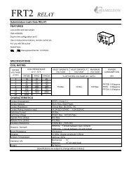
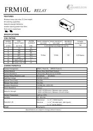
640x480x9.4<br />
<strong>VGA</strong> Cholesteric <strong>Display</strong> & Controller Modules for Graphic, Text and Terminal Applications<br />
Typical Applications<br />
o Battery Powered, Portable <strong>Display</strong>s o Instrumentation <strong>Display</strong>s<br />
o General Purpose Indoor or Outdoor Signage o eBook<br />
o Point of Sale <strong>Display</strong>s o VT100 Compatible Terminal <strong>Display</strong><br />
Product Description<br />
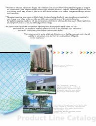
The Kent <strong>Display</strong>s, Inc. 640x480x9.4 <strong>VGA</strong> (640x480)<br />
cholesteric displays are modular units designed for generalpurpose<br />
graphic and character display applications. A<br />
controller module version is also available for “Dumb<br />
Terminal” applicaitons. Intended uses include eBook,<br />
instrumentation, point of sale, terminal and other generalpurpose<br />
indoor/outdoor display applications.<br />
As with all Kent <strong>Display</strong> cholesteric (ChLCD) products, the<br />
<strong>VGA</strong> module contains the same optical and power saving<br />
advantages over traditional LCD products. After an image is<br />
generated on the module, it will remain indefinitely after<br />
power is removed, until a new image is created.<br />
<strong>Display</strong> Only Features:<br />
o<br />
o<br />
o<br />
o<br />
o<br />
o<br />
o<br />
o<br />
o<br />
640 x 480 pixels, 85 dpi, 240 mm (9.45”) diagonal<br />
image area.<br />
Battery powered capability (3.5-9 VDC).<br />
Operates using 5V logic (3V as non-standard).<br />
Graphic or character generation capability.<br />
Full or Partial Screen Update Capability<br />
Dynamic Update Capability, including:<br />
Wipe, Scroll, Rotate, Open, Close, Flashing,<br />
Swell and Fade.<br />
Indefinite image memory capability.<br />
360 degree unlimited viewing angle.<br />
Superior brightness & optical characteristics<br />
<strong>Display</strong> w/Optional Controller Features:<br />
o<br />
o<br />
o<br />
o<br />
o<br />
o<br />
o<br />
o<br />
o<br />
o<br />
o<br />
Up to 31 controllers can be controlled from a host<br />
computer (Unique Address capability).<br />
Battery powered capability (3-9 VDC Input).<br />
Automatic Wake/Idle & Sleep mode capability.<br />
Local diagnostics and control.<br />
*Stores up to 27 unique messages per display.<br />
640, 2048, 3840 or 6360 Characters/<strong>Display</strong> w/ Text<br />
Generator.<br />
4 unique fonts, and font controls w/ Text Generator.<br />
Automatic message generation capability.<br />
RS-232, RS-485, TTL and/or RF “wireless” interface.<br />
<strong>VGA</strong>Soft, Windows-Based Software supplied with<br />
product, provides the following features:<br />
Text and Graphical Editor.<br />
Message/ Image Storage & Retrieval.<br />
VT100 Compatable Terminal Emulation (w/10120-26)<br />
* Based on controller module, storing full screen, larger font text messages<br />
Kent <strong>Display</strong>s Inc<br />
343 Portage Blvd.<br />
Kent, OH 44240, USA<br />
Tel (330) 673 8784<br />
Fax (330) 673 4408<br />
sales@kentdisplays.com<br />
website: www.kentdisplays.com<br />
640x480x9.4 <strong>VGA</strong> <strong>Display</strong> Module<br />
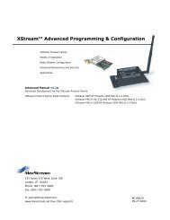
<strong>VGA</strong> <strong>Display</strong> Mechanical Drawing (in mm)<br />
Product Ordering Information:<br />
See detailed Ordering Information & list on next sheet.<br />
25053e 070202, (c) 2002 Kent <strong>Display</strong>s Inc. Page 1 of 12
640x480x9.4<br />
<strong>VGA</strong> Cholesteric <strong>Display</strong> & Controller Modules for Graphic, Text and Terminal Applications<br />
640x480 Product Ordering Information:<br />
Catalog Number<br />
(KDI P/N 15346)<br />
*Logic Level Configuration:<br />
5V = 0-5V Logic Level Signals<br />
(Sample <strong>Display</strong> Part Number)<br />
640x480x9.4 5V H YEL<br />
Interface Connector Configuration:<br />
H = Header installed (2x10, 2mm)<br />
F = Flex Header installed (1x20, 1mm)<br />
ChLCD/Background Color Options:<br />
YEL = Yellow/Black<br />
YLG = Yellow-Green/Black<br />
WHT = White/Blue<br />
GRN = Green/Black<br />
* - A non-standard “3V-F” configuration is available per<br />
request.<br />
(Sample Controller Part Number)<br />
10120 14<br />
Controller Communication and Address<br />
Configuration:<br />
14 = RS-232 Port w/o Address Switches<br />
(Standard)<br />
15 = RS-485 Port w/o Address Switches<br />
16 = TTL Port w/o Address Switches<br />
17 = RS-232 Port w/ Address Switches<br />
18 = RS-485 Port w/ Address Switches<br />
19 = TTL Port w/ Address Switches<br />
26 = RS-232 Port for VT100 Terminal<br />
Emulation Applications.<br />
Model Number<br />
(Sample L<strong>VGA</strong> Product Development Kit)<br />
90022-WHT<br />
(RF Slave Module Part Number)<br />
10158<br />
(RF Host Box Part Number)<br />
10146<br />
Typical <strong>VGA</strong> Module and Related Product Ordering Examples:<br />
640x480x9.4-5V-F-YLG<br />
<strong>VGA</strong> Yellow-Green/Black <strong>Display</strong> Module, 5V interface, 1 mm pitched flex header installed<br />
(contacts away from display).<br />
640x480x9.4-5V-H-GRN<br />
<strong>VGA</strong> Green/Black <strong>Display</strong> Module, 5V interface, 2x10, 2 mm pitched header installed<br />
(standard).<br />
10120-14 Standard 640x480 Controller Module, with RS-232 port, without address switches.<br />
90022-YEL<br />
640x480 Product Development Kit with Yellow/Black <strong>Display</strong> (1 “-5V-H” display, standard<br />
controller, software, COMM & power cables, documentation and technical support are<br />
provided).<br />
10120 Controller Mechanical Drawing 10158 RF Slave Mechanical Drawing<br />
25053e 070202, (c) 2002 Kent <strong>Display</strong>s Inc. Page 2 of 12
640x480x9.4<br />
<strong>VGA</strong> Cholesteric <strong>Display</strong> & Controller Modules for Graphic, Text and Terminal Applications<br />
General <strong>Spec</strong>ifications – 640x480x9.4 <strong>Display</strong> Modules<br />
Parameter Value/Description Units<br />
<strong>Display</strong> Panel Resolution and<br />
Format<br />
Cholesteric reflective LCD (ChLCD) material with contrasting color background,<br />
640 columns by 480 rows.<br />
Pixel Pitch .30 (84.67 DPI) mm<br />
Pixel Size 0.27 x 0.27 mm mm<br />
ChLCD Image Area Dimensions 191.97 x 143.97 (239.96 mm, 9.45” diagonal)<br />
mm<br />
<strong>Display</strong> Viewing Area<br />
192.97 x 144.97 mm<br />
Dimensions<br />
Bezel Outside Dimensions 213.35 x 165.35 mm<br />
<strong>Display</strong> Module Weight 297.5 (0.656lb) g<br />
*Operating Temperature Range 0 to 70 °C<br />
**Image Clearing Temperature<br />
All <strong>Display</strong> Configurations ∼90-95 °C<br />
Storage Temperature Range -40 to +100** °C<br />
Illumination Source<br />
None (reflective technology).<br />
Full Image Update Rate:<br />
Typical all module types Less than 2.8 (in 1x mode, @ 23.5 °C. ½ the duration if 2x mode, ... 1/8 the Sec.<br />
duration in 8x mode. Refer to graph on subsequent sheet)<br />
UV Protection<br />
98% blocking of 380 nm and lower spectral components is recommended<br />
Recommendations<br />
Recommended Transparent Acrylite OP-3-P-99, matte finish, with UV blocker, or equivalent<br />
Plastic <strong>Display</strong> Cover<br />
Recommended Mating<br />
Connector Socket<br />
“-F” configurations: 1.0 mm pitched 20 conductor flex, Parlex p/n 1.00mm-20-87-B-<br />
OS or equiv., matching header, Molex P/N 71220-2000 or<br />
equiv.<br />
“-H” configurations: 2.0 mm pitched, 2x10 socketed header, Samtec P/N TLE-110-<br />
01-GT-DV, or equivalent ribbon cable plug, Samtec P/N<br />
TCSD-10-01-N<br />
*. <strong>Display</strong>s and controllers have been tested to operate between -20-70 °C, however electronics can only be guaranteed between 0 and 70 °C.<br />
Image quality may degrade at temperatures above 70 °C.<br />
** <strong>Display</strong> will not retain image if the display temperature is greater than specified clearing temperature.<br />
Electrical Characteristics – 640x480x9.4 <strong>Display</strong> Modules<br />
Parameter Min. Typ. Max. Units Condition<br />
Power Source Voltage (V CC) 4.75 5.0 5.25 V DC T A = 25 °C<br />
Power Source Voltage (V DD) 3.5 9.0 V DC T A = 25 °C<br />
High Level Logic Input Voltage (V IH) 4.75 V DC<br />
Low Level Input Voltage (V IL) 0.8 V DC<br />
*Average Operating Power, Enabled Active (P EA) 285 1055 mW EN_PWR = High, checkerboard<br />
image driven on display<br />
**Average Operating Power, Enabled Inactive<br />
(P EI)<br />
175 mW EN_PWR = High, All inputs at<br />
steady state<br />
***Average Operating Power, Not Enabled (P NE) 0.015 mW EN_PWR = Low<br />
Power w/ <strong>Display</strong> Disconnected & Maintaining<br />
0 mW V CC & V DD removed from<br />
Image<br />
display.<br />
* Indicates power draw from V DD while the display is updating (EN_PWR & ENABLE active). . Max power output is during brief bulk erase<br />
(~100ms @ 25 C o )<br />
** Indicates power draw from V DD while the display is not updating & EN_PWR is active & ENABLE inactive.<br />
*** Indicates power draw from V DD while the display is not updating & EN_PWR inactive.<br />
Note: All measurements taken with DMM at 5V Vcc, 3.5V V DD<br />
25053e 070202, (c) 2002 Kent <strong>Display</strong>s Inc. Page 3 of 12
640x480x9.4<br />
<strong>VGA</strong> Cholesteric <strong>Display</strong> & Controller Modules for Graphic, Text and Terminal Applications<br />
Interface Connections – 640x480x9.4-5V-H, Configuration <strong>Display</strong> Module (J1)<br />
Pin # Symbol I/O Description<br />
15 HV_CTL I Optional (recommended) Function Pin that can be used to control the High<br />
Voltage Converter Amplitude (Connect to V ss if not used).<br />
7 LATCH I “Latch” column image data to ChLCD material and reset the column data pointer<br />
(triggered at trailing edge).<br />
13 C_CLK I Clock Column data present on the 8-bit data bus (trailing edge triggered).<br />
9 PHASE I Phase. Dictates polarity and frequency of applied ChLCD waveform.<br />
11 R_CLK I Clock Row data present on the row data input, D0 (trailing edge triggered).<br />
5 ENABLE I When disabled (low), all driver outputs at a ground potential.<br />
3 EN_PWR I Enable Power. Turn on module DC-DC converter & enable data input.<br />
20 TEMP_CTL O Analog ChLCD material temperature output (not required for operation).<br />
4 D0, Row Data I Data element 0 of column data bus, Row Data input.<br />
6 D1 I Data element 1 of column data bus.<br />
8 D2 I Data element 2 of column data bus.<br />
10 D3 I Data element 3 of column data bus.<br />
12 D4 I Data element 4 of column data bus.<br />
14 D5 I Data element 5 of column data bus.<br />
16 D6 I Data element 6 of column data bus.<br />
18 D7 I Data element 7 of column data bus.<br />
2 V SS (power GND) Pwr Power return termination point<br />
1 V DD Pwr Positive DC, power supply voltage (3.5 to 9 VDC, Battery or system power source)<br />
19 V CC Pwr Positive 5-Volt DC, Logic Power termination point<br />
17 No Connect -- Spare interface termination<br />
Notes:<br />
1. All inputs are 0-5 Volt logic inputs, with exception of EN_PWR.<br />
Interface Connections – 640x480x9.4-5V-F, Configuration <strong>Display</strong> Module (J3)<br />
Pin # Symbol I/O Description<br />
1 HV_CTL I Optional (recommended) Function Pin that can be used to control the High<br />
Voltage Converter Amplitude (Connect to V ss if not used).<br />
2 LATCH I “Latch” column image data to ChLCD material and reset the column data pointer<br />
(triggered at trailing edge).<br />
3 C_CLK I Clock Column data present on the 8-bit data bus (trailing edge triggered).<br />
4 PHASE I Phase. Dictates polarity and frequency of applied ChLCD waveform.<br />
5 R_CLK I Clock Row data present on the row data input, D0 (trailing edge triggered).<br />
6 ENABLE I When disabled (low), all driver outputs at a ground potential.<br />
7 EN_PWR I Enable Power. Turn on module DC-DC converter & enable data input.<br />
8 TEMP_CTL O Analog ChLCD material temperature output (not required for operation).<br />
9 D0, Row Data I Data element 0 of column data bus, Row Data input.<br />
10 D1 I Data element 1 of column data bus.<br />
11 D2 I Data element 2 of column data bus.<br />
12 D3 I Data element 3 of column data bus.<br />
13 D4 I Data element 4 of column data bus.<br />
14 D5 I Data element 5 of column data bus.<br />
15 D6 I Data element 6 of column data bus.<br />
16 D7 I Data element 7 of column data bus.<br />
17 V SS (power GND) Pwr Power return termination point<br />
18 V SS (power GND) Pwr Power return termination point<br />
19 V DD Pwr Positive DC, power supply voltage (3.5 to 9 VDC, Battery or system power source)<br />
20 V CC Pwr Positive 5-Volt DC, Logic Power termination point<br />
Notes:<br />
1. All inputs are 0-5 Volt logic inputs, with exception of EN_PWR.<br />
Detailed Product Description<br />
The Kent <strong>Display</strong>s 640x480 <strong>Display</strong> modules are modular units designed for general-purpose text and graphic display applications. Intended<br />
uses include instrumentation devices, portable battery powered displays, point of sale and other general-purpose indoor/outdoor sign<br />
applications.<br />
25053e 070202, (c) 2002 Kent <strong>Display</strong>s Inc. Page 4 of 12
640x480x9.4<br />
<strong>VGA</strong> Cholesteric <strong>Display</strong> & Controller Modules for Graphic, Text and Terminal Applications<br />
Use of the 640x480 display module without the separate 10120 controller is for customers who intend to drive the display with their own custom<br />
controller or CPU board. The pin out description for the parallel interface provided is described in the Interface Connection table above.<br />
Kent <strong>Display</strong>s cholesteric liquid crystal displays (ChLCD) are an advanced reflective display technology, which contains a BI-stable non-volatile<br />
memory feature. After an image is written to the ChLCD, the image will remain indefinitely until a new image is generated. The image will<br />
remain on the module display after power is removed. It does not require “power consuming” update signals to retain the image as with<br />
traditional LCD technologies. Furthermore, since the technology is completely reflective, no “power robbing” backlight is required to generate a<br />
high quality image. The memory and reflective features enable the display to be very energy efficient, enabling long life battery operation.<br />
Since a ChLCD does not reflect polarized light, it exhibits a much wider viewing angle over traditional LCD technologies. Extremely high<br />
contrast characteristics are exhibited consistently at viewing angles near the edge of the display in all directions. The display also exhibits<br />
excellent sunlight readability characteristics. The more light put onto the display face, the brighter the image will appear.<br />
The <strong>VGA</strong> 640x480x9.4 display and 10120 Controller modules configured as indicated in Application Block Diagram will contain the following<br />
features:<br />
To Host<br />
Computer<br />
RF, RS-485 or Equiv.<br />
Serial Interface<br />
<strong>VGA</strong><br />
Controller<br />
Module #1<br />
<strong>VGA</strong><br />
Controller<br />
Module #2<br />
<strong>VGA</strong><br />
<strong>Display</strong><br />
Module<br />
<strong>VGA</strong><br />
<strong>Display</strong><br />
Module<br />
<strong>VGA</strong><br />
Controller<br />
Module #N<br />
<strong>VGA</strong><br />
<strong>Display</strong><br />
Module<br />
Notes: N
640x480x9.4<br />
<strong>VGA</strong> Cholesteric <strong>Display</strong> & Controller Modules for Graphic, Text and Terminal Applications<br />
e. Rotate ON<br />
f. Flashing, Fade and Swell<br />
Updating display sections in this mode provides an animation sequence, allowing the user to view multiple frames of data in a<br />
moving sequence. Kent <strong>Display</strong>s patented “Cumulative Drive TM ” techniques enables this feature. The most common application<br />
for this type of update method is to display numbers entered on a keypad in a scrolling fashion, frame by frame as the numbers are<br />
entered. Different “ON” and “OFF” presentation methods are also possible using the controller protocol and <strong>VGA</strong> Interface software<br />
provided with the products. The user simply has to enter the text, or create a graphic image (Using the Graphic editor activated by<br />
the <strong>VGA</strong>Soft) to output in the static frame, and the <strong>VGA</strong> controller will create the frame sequences automatically for the user! The<br />
user can also make the image section larger (for instance, a 10 row font can be output using 20, 30, ... 80 rows of the display) by<br />
selecting the corresponding height adjustment feature on the user interface software. Parameters on flashing images, such as the<br />
Invert and non-invert image duration’s and the number flashes for the respective display image can also be dictated by the user. The<br />
<strong>VGA</strong> Interface software provides a nice windows-based human interface to control these features.<br />
o<br />
o<br />
o<br />
o<br />
When using the <strong>VGA</strong> controller text generator, the user can select between a 30 row fonts, a 15-row font, a 10-row font and a<br />
5x7 character font. Using the 30-row font, up to 40 characters/line and 16 lines of text can be generated on the display. Using the<br />
15-row font, up to 64 characters/line and 32 text lines can be output on a display. Using the 10 row font, up to 80 characters /line and<br />
48 lines of text can be output on the displays. The 5x7 font can be used to output 106 characters/line and 60 lines of text. Using<br />
partial screen text images can also alter a text line within a full screen image. Text based objects can be “Stretched” vertically to 2x,<br />
3x, ... 8x their size to increase the update speed by 2x, 3x,.. 8x the normal duration. However, the number of text lines per screen is<br />
½ with the 2x feature, 1/3 with the 3x feature, ... 1/8 with the 8x feature. The user can also use the windows-based text generator on<br />
the graphic editor activated by the <strong>VGA</strong>Soft to create text based graphical images for output on the display panels. All the described<br />
features are available and demonstrated with the <strong>VGA</strong>Soft software, provided with the product.<br />
The Kent <strong>Display</strong>s automatic “Wake/Idle/Sleep mode” is a standard feature, which supports extended life battery operation. If no<br />
messages or data is received from the host computer after a pre-determined duration, or no local diagnostic/control activity is sensed<br />
by the controller logic, the module will reduce power consumption by activating an “Idle” mode operation automatically. If the <strong>VGA</strong><br />
controller senses no further activity, it will remove the load from the 3.5-9 volt power source. In “Sleep mode”, the display module will<br />
contain the image generated, and power consumption will be less than 6 microwatts (power required to maintain the sleep control<br />
circuitry, RS-232 & RS-485 versions). The module will “wake-up” and resume normal operation after it receives the host wake-up<br />
signal.<br />
Automatic temperature compensation circuitry to extend the module operating temperature range to -20 and 80 C 0 (standard<br />
module electronics can only be guaranteed from 0 to 70 C 0 )<br />
Diagnostic switches and an LED indication to support local operation and control.<br />
25053e 070202, (c) 2002 Kent <strong>Display</strong>s Inc. Page 6 of 12
640x480x9.4<br />
<strong>VGA</strong> Cholesteric <strong>Display</strong> & Controller Modules for Graphic, Text and Terminal Applications<br />
General <strong>Spec</strong>ifications – 10120 Controller with 640x480x9.4 <strong>Display</strong> Modules<br />
Parameter Value/Description Units<br />
30 Row Character Pixel Configuration/ 16 pixels wide by 30 pixels high/ 640 Characters per <strong>Display</strong> / 16 Text Lines (1x --<br />
Characters per <strong>Display</strong>/ Lines per <strong>Display</strong>. configuration. ½ the # of Text lines if 2x configuration, ... 1/8 th text lines if 8x)<br />
15 Row Character Pixel Configuration/ 10 pixel wide by 15 pixels high/ 2048 Characters per <strong>Display</strong>/ 32 Text Lines (1x --<br />
Characters per display/ Lines per <strong>Display</strong> mode)<br />
10 Row Character Pixel Configuration/ 8 pixel wide by 10 pixels high/ 3840 Characters/ 48 Text Lines (1x mode) --<br />
Characters per display/ Lines per <strong>Display</strong><br />
5x7 Character Pixel Configuration/ 6 pixel wide by 8 pixels high/ 6360 Characters/ 60 Text Lines (1x mode) --<br />
Characters per display/ Lines per <strong>Display</strong><br />
Text Generator Character Set Capability 30 Row: Modified Letter Gothic Bold 22 point. 15 Row: Modified Fixed Distance 11 --<br />
point. 10 Row: Modified Fixed Distance 9 point (default). 5x7: Typical 5x7<br />
characters.<br />
Character Set Controls Underline. --<br />
# <strong>Display</strong> Modules/ Controller 1 (more displays can be “Daisy Chained” from controller header, however additional --<br />
displays will contain the same image information as display position #1).<br />
Message Storage Capability<br />
58,400 Bytes, equating to 27 Full Screen large font Text, 9 Full screen small font --<br />
text, 1 Full Screen Graphic (<strong>VGA</strong> Mode), 6 Full screen graphic (1/4 <strong>VGA</strong> Mode), 474<br />
Partial Screen Text (Dyn. Update, Flashing or Normal), 6 Partial Screen Graphic, or<br />
45 Partial Screen Dynamic Update Graphic Messages per display.<br />
Operating Temperature Range<br />
All controller configurations: *-20 to 80 C o<br />
Storage Temperature Range -40 to +100 C o . C o .<br />
Possible Controller Address Selections 31 (standard, more are available per request)<br />
Standard Total Wakeup Duration without 20 (Typical) Sec.<br />
communication or local activity<br />
Standard Active Wakeup Duration Before<br />
implementing Idle Mode<br />
10 (Typical) Sec.<br />
* Indicates display electronics can only be guaranteed between 0 and 70 o ambient. Update rates will be slower at lower temperature extremes.<br />
Image quality may degrade at operating temperatures above 70 C 0 .<br />
Power Requirements (10120 Controller Module)<br />
Power Source (V DD) ***1.1 – 10 (T = 25 C 0 ) VDC<br />
**Average “Wake-up” Active Mode Power 129 (typical, w/ V battery = 6.0 volts, T = 25 C 0 ), 123 (typical, w/ V Battery = 3.0 volts, T = mW<br />
Consumption (10120-14)<br />
25 C 0 )<br />
**Average “Wake-up” Idle Mode Power 114 (typical, w/ V Battery = 6.0 volts, T = 25 C 0 ) , 105 (typical, w/ V Battery = 3.0 volts, T mW<br />
Consumption (10120-14)<br />
= 25 C 0 )<br />
**Average “Sleep Mode” Power<br />
Less than 6 microWatts (w/ V Battery = 3.0 - 6.0 volts, T = 25 C 0 , RS-232, RS-485), uW<br />
Consumption.<br />
Less than 72 microWatts (w/ V Battery = 3.0 - 6.0 volts, T = 25 C 0 , TTL Port Versions)<br />
Recommended Power Interface (J6) Standard 2.54 mm pitched via’s in PCB.<br />
* Indicates display electronics can only be guaranteed between 0 and 70 o ambient. Update rates will be slower at lower temperature extremes.<br />
Image quality may degrade at operating temperatures above 70 C 0 .<br />
** Values indicate average power measurements taken when not generating images (using a DVM). Power values provided for display should be<br />
added to “Active Mode” power value above, when considering total power values when image generation occurs.<br />
*** Indicates power source must be able to supply sufficient current when battery approaches lower specified voltage limit.<br />
25053e 070202, (c) 2002 Kent <strong>Display</strong>s Inc. Page 7 of 12
640x480x9.4<br />
<strong>VGA</strong> Cholesteric <strong>Display</strong> & Controller Modules for Graphic, Text and Terminal Applications<br />
General <strong>Spec</strong>ifications – 10120 Controller with 640x480x9.4 <strong>Display</strong> Modules (Con’t)<br />
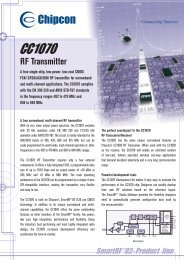
Dynamic Update Information (“Cumulative Drive TM ”)<br />
Frames/Second<br />
35<br />
30<br />
25<br />
20<br />
15<br />
10<br />
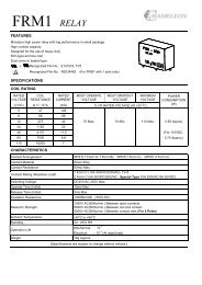
<strong>VGA</strong> Dynamic Update Frame Rates<br />
13.1<br />
17.9<br />
20<br />
23.8<br />
27.8<br />
29.4<br />
31.3<br />
5<br />
4.3 5.6<br />
0<br />
1.6 2.1<br />
0 20 40 60 80 100<br />
Temperature (C)<br />
Frame rates illustrated reflect measurements taken of the dynamic update of a 10 row (or 20,<br />
30, .. 80 row if “2x, 3x,..-8x” feature implemented) 640x480x9.4 display section during the<br />
presentation “ON” of a particular image. A slightly faster frame rate will occur when<br />
measuring the presentation “OFF” of an image. As indicated, a typical frames rate of nearly<br />
18 frames/second can be expected at room temperatures (23.5 C 0 ).<br />
Full Screen Update Rate Information<br />
The chart to the left illustrates the maximum frame<br />
rates possible with the 10120 controllers and <strong>VGA</strong>display<br />
combination. The following additional features<br />
are provided and can be programmed for each<br />
dynamic update message loaded into the controller<br />
RAM:<br />
1. Scroll, Wipe, Open, Close and Rotate<br />
presentation methods.<br />
2. Different ON and OFF presentation methods<br />
are available for each message (i.e. Rotate ON,<br />
Pause, then Scroll OFF).<br />
3. Pause Duration’s to allow the requested static<br />
frame to remain on the display between ON &<br />
OFF presentation methods are programmable<br />
from 0.1 to 25.5 seconds, in 0.1-second<br />
increments.<br />
4. “2x – 8x” feature – Graphic or text data can be<br />
doubled, tripled, ... or eight times in size<br />
vertically to create a larger image update area.<br />
5. Image invert or non-invert characteristics.<br />
The controller module is also capable of generating<br />
flashing text messages, allowing the user to dictate<br />
the invert pause duration, non-invert duration (each<br />
can be set up to 25.5 seconds, in 0.1 second<br />
increments), and the number of flashing cycles to<br />
implement.<br />
Static frames of data can also be output in a “Swell”<br />
and “Fade” modes, which enhance image<br />
appearances or aesthetics during the update process.<br />
Seconds<br />
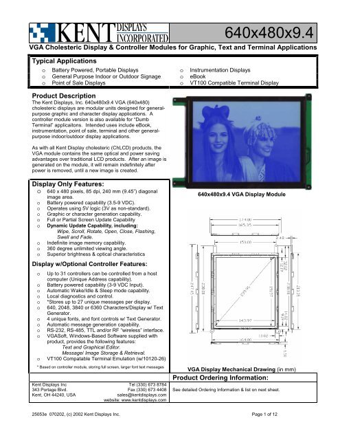
<strong>VGA</strong> Full Screen (@ 1x) Update Duration (Seconds)<br />
1,350.0<br />
173.0 180.0<br />
32.0 35.0<br />
8.2<br />
9.5<br />
5.74.22.8<br />
2.4 2.2 1.7 1.5<br />
-40 -20 0 20 40 60 80 100<br />
Temperature<br />
1.1<br />
The chart to the left illustrates measured full<br />
screen (all 480 rows) update durations when<br />
configured to the slowest 1x mode, with respect<br />
to temperature for a 640x480x9.4 display and<br />
10120 controller module. As indicated on the<br />
chart, a typical update duration of 2.8 Seconds<br />
can be expected at typical room temperatures<br />
(23.5 C). When configured to 2x mode, ½ the<br />
durations indicated can be expected. When<br />
configured to 3x mode, 1/3 the durations<br />
indicated can be expected. .... When configured<br />
to 8x mode, 1/8 th the durations indicated can be<br />
expected.<br />
If faster full screen update rates are necessary,<br />
the 640x480x9.4 display module can be<br />
configured to drive in “Dynamic Drive TM ” mode<br />
as a custom module. In this configuration, 1x<br />
update durations of 4 to 5 times faster than the<br />
durations indicated to the left can be expected.<br />
The graph above reflects full screen update duration (when configured to the slowest 1x mode, where<br />
all 480 rows contain unique data) measurements taken on 640x480x9.4 displays at the temperatures<br />
indicated. As indicated, a typical update duration of 2.8 Seconds can be expected at room<br />
temperatures (23.5 C 0 ).<br />
25053e 070202, (c) 2002 Kent <strong>Display</strong>s Inc. Page 8 of 12
640x480x9.4<br />
<strong>VGA</strong> Cholesteric <strong>Display</strong> & Controller Modules for Graphic, Text and Terminal Applications<br />
10120 Controller Module Communication Interfaces/Information<br />
Serial Communication Format RS-232 (10120-14, 10120-17 & 10120-26 Modules): Asynchronous, full duplex, 8 bits/byte, 1<br />
Stop, no parity. RS-485 (10120-15 & 10120-18 Modules): half duplex, Everything else same.<br />
TTL (10120-16 & 10120-19 Modules): Asynchronous, full duplex, 8 bits/byte, 1 Stop, no parity.<br />
Standard Baud Rate:<br />
19.2k Baud (other rates, such as 38.4k, 9600, 4800, 2400 & 1200 are available per request).<br />
Standard Protocol Format<br />
Standard Kent <strong>Display</strong>s Character/Graphic Serial Protocol (refer to Kent <strong>Display</strong>s document<br />
25016 for details).<br />
Recommended Matting Communication<br />
Plug<br />
Standard 2mm pitched 3-socketed plug; Hirose P/N DF3-3S-2C w/ DFS-2428SC crimped<br />
contacts, or equivalent (RS-232 & RS-485 Configurations)<br />
Standard 2mm pitched 4-socketed plug; Hirose P/N DF3-4S-2C w/ DFS-2428SC crimped<br />
contacts, or equivalent (TTL Configurations)<br />
Module Interconnect Descriptions<br />
The following interconnect rules apply when installing only the 640x480x9.4, <strong>VGA</strong> display module into the finished product:<br />
1. Mount the display module into the finished product using the four mounting holes on the module printed circuit board and bezel<br />
frame.<br />
2. In order to preserve the quality and life of the display, the finished product design should incorporate a transparent protective cover to<br />
protect the viewing area of the display. Use a material that can block UV light, has anti-glare properties and provides protection from<br />
user applied pressure points.<br />
3. Mount the cover as close as possible to the face of the display. Use Acrylite OP-3-P-99, matte finish, with UV blocker, or equivalent<br />
material.<br />
4. Connect J1 (“-H” configuration) or J3 (“-F” configuration) of the display module to the user’s CPU based electronic assembly.<br />
The following additional interconnect rules apply when installing the 640x480x9.4, <strong>VGA</strong> display and 10120 controller module into the finished<br />
product, as indicated in following figure:<br />
RS-232/485 to<br />
Host Computer<br />
J4<br />
J6<br />
To Battery Source<br />
TTL to Host<br />
Computer<br />
J2<br />
10120 Controller Module<br />
J5<br />
To RF Slave<br />
Module (Optional)<br />
J7<br />
J1<br />
640x480x9.4 <strong>VGA</strong> <strong>Display</strong> Module<br />
Typical Controller to <strong>Display</strong> Interconnect Diagram<br />
a. Apply the same steps for the display module as indicated in step 1 through 4 above.<br />
b. As indicated in Typical Controller to <strong>Display</strong> Module Interconnect Diagram above, attach J7 of the controller module to J1 of the<br />
display by either a direct “Header to Header” connect (be sure to align pin 1 of J7 to pin 1 of J1), or by installing a ribbon cable<br />
assembly (consisting of two 2x10, 2 mm pitched plugs and 1 mm pitch ribbon cable) between the 2 specified header locations. If<br />
25053e 070202, (c) 2002 Kent <strong>Display</strong>s Inc. Page 9 of 12
640x480x9.4<br />
<strong>VGA</strong> Cholesteric <strong>Display</strong> & Controller Modules for Graphic, Text and Terminal Applications<br />
installing a direct “Header to Header” configuration, the short component side of the controller should be facing the back of the<br />
display, with the portion of the controller containing the diagnostic switches and LED extended from the left side of the display.<br />
c. Connect the battery or power source terminals of the finished product to J6 of the controller module. Any standard 0.1” type header,<br />
connector or open wires can be used as a power interface. Verify the DC power source applied does not exceed 10.0 volts DC.<br />
Verify the positive terminal of the source is connected to J6 pin 1 (Marked with Pad/via)<br />
d. Connect to the host computer either using the J4 header location (RS-232 or RS-485), or to J2 (if a TTL, or 0-5 VDC serial interface is<br />
required). Use the plugs and terminations specified in the 10120 Controller Module Communication Interfaces/Information table of this<br />
document (above).<br />
e. If using the wireless RF communication option, mount the 10158 RF slave module into the finished product in a position to enable the<br />
module antenna to be exposed to a maximum of the product exterior. Connect the RF slave module to the J5 header on the controller<br />
using the ribbon cable provided with the RF module.<br />
f. If necessary, mechanically mount the controller module to the finished product accordingly using the 4 mounting holes provided, or<br />
using some other equivalent method.<br />
<strong>VGA</strong> Controller Power and Communication Interface Details<br />
The following tables outline all the power and communication terminations for the <strong>VGA</strong>, 10120 controller modules:<br />
Power Interface Connection: J6 – 10120 Controller Modules<br />
Pin # Symbol Description<br />
1 (Marked with Pad/via) + Power Positive Power Termination<br />
2 (Marked with Ο Pad/via) - Power (Return) Negative Power Termination.<br />
RS-232/485 Communication Interface: J4 – 10120 Controller Modules<br />
Pin # Symbol Description<br />
1 RX_DATA Module receive data input termination (RS-232). Positive data communication termination point (RS-485).<br />
Module “Wake” input (Based on parked low condition).<br />
2 Ground Ground termination point.<br />
3 TX_DATA Module transmit data output termination (RS-232). Negative data communication termination point (RS-485).<br />
TTL Communication Interface: J2 – 10120 Controller Modules (Rev. G Controller, or Later only)<br />
Pin # Symbol Description<br />
1 RX_DATA Module receive data input termination (w/ respect to controller module). Module Wake Input (Based on<br />
Parked High condition. Wakes w/ Low input, or when Input is below ~ 0.7 VDC). 0-5 Volt Logic Input.<br />
2 Ground Ground termination point.<br />
3 TX_DATA Controller module transmit data output termination. 0-5 Volt Logic Input.<br />
4 +5 VDC Power Source input to be used for Finished Product Level Shifters circuitry. Source not provided when<br />
Controller is in sleep mode.<br />
Local Control/Diagnostic Descriptions – 10120 Modules<br />
Symbol<br />
Description<br />
“RESET” (SW2)<br />
Controller Reset momentary switch.<br />
“TEST” (SW3)<br />
Controller Diagnostic momentary switch (For local control).<br />
D3<br />
LED Diagnostic Output (For local control feedback).<br />
“WAKE” (SW4)<br />
Module Local “Wakeup” momentary switch.<br />
Address, Bit 1 (R2) Module Address Bit1 (= 1) Shorting Pads (10120-7,-8,-12), or SW1 Bit1 position (10120-9,-10,-13)<br />
Address, Bit 2 (SW1, pins 2-11) Module Address Bit2 (= 2) Shorting Pads (10120-7,-8,-12), or SW1 Bit2 position (10120-9,-10,-13)<br />
Address, Bit 3 (SW1, pins 3-10) Module Address Bit3 (= 4) Shorting Pads (10120-7,-8,-12), or SW1 Bit3 position (10120-9,-10,-13)<br />
Address, Bit 4 (SW1, pins 4-9) Module Address Bit4 (= 8) Shorting Pads (10120-7,-8,-12), or SW1 Bit4 position (10120-9,-10,-13)<br />
Address, Bit 5 (SW1, pins 5-8) Module Address Bit5 (= 16) Shorting Pads (10120-7,-8,-12), or SW1 Bit5 position (10120-9,-10,-13)<br />
Note: a 10120-14, 10120-15, 10120-16 & 10120-26 modules are always set as address #1. The address cannot be changed without<br />
jumper wires. Address setting for 10120-26 module not pertainent or necessary for terminal application.<br />
25053e 070202, (c) 2002 Kent <strong>Display</strong>s Inc. Page 10 of 12
640x480x9.4<br />
<strong>VGA</strong> Cholesteric <strong>Display</strong> & Controller Modules for Graphic, Text and Terminal Applications<br />
Terminal Application for 640x480x9.4 Product:<br />
As indicated previously, the 640x480x9.4 <strong>VGA</strong> display and controller module can be used to emulate a standard VT100 type,<br />
ASCII compatible terminal. The user will need to purchase the 10120-26 controller module with the product.<br />
The following specifications apply to the 640x480x9.4 display and 10120-26 controller module:<br />
General <strong>Spec</strong>ifications – 10120-26 “Terminal” Controller with 640x480x9.4 <strong>Display</strong> Modules<br />
Parameter<br />
Value/Description<br />
Characters <strong>Display</strong>ed per Text line 80 Standard (Terminal can be supplied as a custom unit w/ smaller 5x7 font capable 106<br />
characters/Line)<br />
Characters Stored per Text line<br />
132 <strong>Display</strong>able ASCCI characters Standard.<br />
Standard Font<br />
Modified Fixed Distance 9 stretched to 2x mode (Each character occupies 8x20 pixel space)<br />
Standard Text Characteristics<br />
Bright characters on dark background (standard).<br />
Maximum <strong>Display</strong>able Text Lines / <strong>Display</strong> 23 (Standard)<br />
Text Line Storage Capacity in RAM 410 (Standard minimum)<br />
Curser Characteristics<br />
Blinking Line (4 <strong>Display</strong> rows high), positioned below present character to be entered.<br />
Curser Blink Rate<br />
1 second ON, 1 second OFF continuously (standard default).<br />
Wake/Idle/Sleep mode Characteristics Disabled (standard). Controller will “Wake” after reception of data on serial port, and remain<br />
in active mode indefinitely until power is removed.<br />
Auto-Wrap Feature Enabled (standard). Cursor will automatically move to next line position, left margin after 81<br />
characters are entered for a given line (cursor is still in same text line when Auto-Wrap<br />
condition occurs).<br />
The 10120-26 controller and 640x480x9.4 display module will generate all standard visible ASCII characters (from space ((32<br />
decimal)) to “~” ((126 decimal)) on the display module immediately after reception of the data from the input source (keyboard<br />
input or equivalent). The following non-visible characters are also supported by the controller, which represents a “sub-set” of<br />
the standard VT100 command and control sequences:<br />
Miscellaneous Control Functions<br />
Character Mnemonic Hex Code Actions or functions implemented<br />
CR 0D Moves cursor to left margin, and down 1 line. Indicates end of storage for corresponding text<br />
line.<br />
BS 08 Moves curser to left 1 position (unless cursor at left margin), and deletes any character<br />
previously entered.<br />
CAN 18 If received during an escape or control sequence, the corresponding command is cancelled<br />
Cursor, or “Arrow” Control Functions<br />
Character Mnemonics Hex Codes Actions or functions implemented<br />
ESC [ A 1B 5B 41 Cursor will move UP one text line position.<br />
ESC [ B 1B 5B 42 Cursor will move DOWN one text line position.<br />
ESC [ C 1B 5B 43 Cursor will move to the RIGHT one character position in selected line.<br />
ESC [ D 1B 5B 44 Cursor will move to the LEFT one character position in selected line.<br />
Erase Control Functions<br />
Character Mnemonics Hex Codes Actions or functions implemented<br />
ESC [ 2 J 1B 5B 32<br />
4A<br />
Erases entire screen. Cursor will move to top-left margin position.<br />
* Additional command and control sequences can be added per request.<br />
25053e 070202, (c) 2002 Kent <strong>Display</strong>s Inc. Page 11 of 12
640x480x9.4<br />
<strong>VGA</strong> Cholesteric <strong>Display</strong> & Controller Modules for Graphic, Text and Terminal Applications<br />
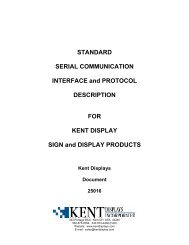
Optical Characteristics for Typical Standard Color Configurations:<br />
Reflectance (%)<br />
35<br />
30<br />
25<br />
20<br />
15<br />
10<br />
Yellow<br />
Black<br />
The graphs to the left outline the spectral reflectance<br />
characteristics for a given display pixel when switched either of<br />
the two possible stable states; reflective planar or transparent<br />
focal conic. The top line in each chart outlines the reflective<br />
characteristics for the planar state. The bottom line outlines the<br />
reflective characteristics for the transparent focal conic state.<br />
Graphs for the 4 standard color combinations are illustrated.<br />
5<br />
400 450 500 550 600 650 700<br />
W avelength (nm )<br />
35<br />
30<br />
White<br />
Reflectance (%)<br />
25<br />
20<br />
15<br />
10<br />
Blue<br />
5<br />
400 450 500 550 600 650 700<br />
W aveleng th (nm )<br />
35<br />
30<br />
Yellow-Green<br />
Reflectance (%)<br />
25<br />
20<br />
15<br />
10<br />
Black<br />
5<br />
400 450 500 550 600 650 700<br />
W avelength (nm )<br />
Contrast Ratio Polar Representation<br />
Reflectance (%)<br />
35<br />
30<br />
25<br />
20<br />
15<br />
10<br />
Black<br />
Green<br />
As illustrated in the polar graph above, all Kent <strong>Display</strong>s ChLCD<br />
products have a 360-degree viewing cone. Contrast at near<br />
normal viewing angles is as high as 25:1 and reflectivity up to<br />
35% of incident light. Contrast reduces with increased viewing<br />
angle, but is still excellent at 11:1 when viewed at the edge of the<br />
display. Since no polarizers are used, display contrast reduces<br />
uniformly in all directions when the viewing angle is increased.<br />
5<br />
400 450 500 550 600 650 700<br />
W avelength (nm )<br />
The above reflectance curves reflect measurements taken from a<br />
single pixel. Actual reflectance will depend on display<br />
resolution, aperture ratio and other factors.<br />
Typical ChLCD <strong>Spec</strong>tral Reflectance<br />
Characteristics<br />
Products and technologies of Kent <strong>Display</strong>s, Inc. are protected by the US Patents: 5,493,430, 5,570,216, 5,636,044, 5,644,330, 5,251,048, 5,384,067,<br />
5,437,811, 5,453,863, 5,668,614, 5,691,796, 5,695,682, 5,748,277, 5,766,694, 5,847,798 and numerous other patent applications by Kent <strong>Display</strong> Systems,<br />
Inc., Kent <strong>Display</strong>s, Inc. and Kent State University pending in the U.S. and in foreign patent filings include: PCT, Canada, China, Europe, Israel, Japan,<br />
Korea, and Taiwan among others.<br />
25053e 070202, (c) 2002 Kent <strong>Display</strong>s Inc. Page 12 of 12