STANDARD SERIAL COMMUNICATION INTERFACE and ...
STANDARD SERIAL COMMUNICATION INTERFACE and ...
STANDARD SERIAL COMMUNICATION INTERFACE and ...

You also want an ePaper? Increase the reach of your titles
YUMPU automatically turns print PDFs into web optimized ePapers that Google loves.
<strong>STANDARD</strong><br />
<strong>SERIAL</strong> <strong>COMMUNICATION</strong><br />
<strong>INTERFACE</strong> <strong>and</strong> PROTOCOL<br />
DESCRIPTION<br />
FOR<br />
KENT DISPLAY<br />
SIGN <strong>and</strong> DISPLAY PRODUCTS<br />
Kent Displays<br />
Document<br />
25016<br />
343 Portage Blvd., Kent OH USA 44240<br />
330 673-8784, 330 673-4408 (FAX)<br />
Website: www.kentdisplays.com<br />
E-mail: sales@kentdisplay.com
St<strong>and</strong>ard Serial Interface Protocol Description<br />
Kent Displays Document 25016,<br />
REVISION RECORD<br />
Revision Date Author Description<br />
A 8/5/98 CRB Released to support the 90014 INFOSIGN Module Dev. Kit<br />
B 10/6/98 CB/TW Modified sections 4.4 Updated sections 5.1, 5.3 <strong>and</strong> 5.3.1.<br />
C 11/24/98 CRB Mod. Sec. 5.2 to reflect INFOSIGN Enhancements<br />
D 1/7/99 CRB Modified ¼ VGA section (5.1) to account for increased message storage & selective<br />
addressing capability. Added section 5.1.1.<br />
E 2/11/99 CRB Added Broadcast Message Section (4.4)<br />
F 5/5/99 CRB Mod. 5.1.x Sections for ¼ VGA 15126G03 Display.<br />
G 9/28/99 CB/TE Mod. 5.2 to h<strong>and</strong>le additional font controls & “N” Cmd, added section 5.4.<br />
H 10/7/99 CB/TE Added J, M & U comm<strong>and</strong>s to section 5.2. Fixed information<br />
for the 1/8 VGA Appl.<br />
I 3/23/00 CRB Added/Modified Section 5.5, Again<br />
J 4/11/00 CRB Added “Rotate ON” bullet to section 5.5.<br />
K 5/24/00 - CRB<br />
10/27/00<br />
Added App. Cmds to INFOSign Protocol to support mixed-mode operation (Added<br />
Section 5.2.1, Table 5.2.2 <strong>and</strong> 3-Line font to section 5.2.2). Added “Z” cmd. to Table<br />
5.2.1. Removed Sample INFOSIGN App. Source Code Section.<br />
L 2/7/01,<br />
4/13/01<br />
CRB Added “;” comm<strong>and</strong> (table 5.2.1), “4” & “5” comm<strong>and</strong>s (table 5.2.3), <strong>and</strong> modified<br />
table 5.2.3, <strong>and</strong> sections 5.2.1 <strong>and</strong> 5.2.2, to support new INFOSign III product.<br />
M 4/20/01 TE Added (Does not display after valid message RX’ed) to Table 5.4.1 N & U comm<strong>and</strong>.<br />
N 6/18- CB/ReA Added >, Y & Z App. Cmds. To QUAD application, table 5.3.1.<br />
7/27/01<br />
O 8/16/01 - CRB, Added sections 5.6 & 5.7, Added "Swell-ON" & "Fade-ON" bullets to section 5.5.<br />
10/11/01 TE<br />
P 11/01/01; ReA Modified Height Multiplier for Dynamic Update of INFOSign III (Section 5.2.1)<br />
12/3/01<br />
Q 1/3/02,<br />
1/18-<br />
5/3/02<br />
CRB Added Dynamic Update, Partial screen & Dynamic Memory type application<br />
comm<strong>and</strong>s to 1/8 VGA section (section 5.4), to support the 10120 controller. Added<br />
LVGA Section (Section 5.7).<br />
R 6/27/02 CRB Modified (“Sectionalized“) LVGA Graphic Data Comm<strong>and</strong>s in section 5.7<br />
S 8/28/02,<br />
9/4/02,<br />
9/10/02,<br />
11/1/02<br />
CRB Added sectioin 5.8 for New ¼ VGA 15297 Display Module.<br />
Added 2x Horz. Capability to Dynamic Update Parameter, for 320x80 app., Sect. 5.6.<br />
Changed “Message” terminology to “Packet” to avoid confusion when describing<br />
lower level packet components, Section 4. Added text <strong>and</strong> re-named section 4.1.1.<br />
T 12/21/02 CRB Removed old 1/4 VGA App. Lev. Section (4.1). Removed old app. comm<strong>and</strong>s from<br />
INFOSign section (5.2). Added some INFOSign App. features, in Dynamic Update<br />
parameter features (Horz. Stretch), Font Controls, Flashing, Swell & Fade.<br />
St<strong>and</strong>ard Serial Communication Interface Description, © 1998-2002 Kent Displays Inc., doc. # 25016 Revision T, Page 1 of 52
St<strong>and</strong>ard Serial Interface Protocol Description<br />
Table of Contents<br />
1.0 Introduction .......................................................................................................... 3<br />
2.0 ChLCD Technology <strong>and</strong> Display/Sign Product Description ............................. 3<br />
3.0 Interface or Communication Protocol Description............................................ 4<br />
4.0 Lower Level Communication Protocol Description .......................................... 4<br />
4.1 Host Comm<strong>and</strong> Format to the Master Display Modules........................................................... 4<br />
4.1.1 Additional Host Comm<strong>and</strong> Communication Requirements <strong>and</strong> RF Operation 5<br />
4.2 Sign Response Protocol Format to a Host Comm<strong>and</strong>.............................................................. 6<br />
4.3 Host <strong>and</strong> Sign Module Communication Action Description .................................................... 7<br />
4.4 Broadcast Messages.................................................................................................................... 7<br />
4.5 Sample Host Lower Level Communication Protocol Code...................................................... 8<br />
5.0 Application Level Comm<strong>and</strong> Designations...................................................... 10<br />
5.2 INFOSign II <strong>and</strong> III Host to Sign Application Level Comm<strong>and</strong> Descriptions (Mixed Mode) 11<br />
5.2.1 Special “0”, “2”, “4” <strong>and</strong> “6” Font Control Characters 14<br />
5.2.2 Maximum Number of INFOSign Messages or Pages 15<br />
5.2.2.1 Controlling <strong>and</strong> Determining the Message Count 16<br />
5.3 QUAD Application Layer Com<strong>and</strong> Descriptions ..................................................................... 16<br />
5.3.1 Special "A" through "H" & “Y” Comm<strong>and</strong> Text Control Characters 19<br />
5.4 1/8 VGA Controller Host to Display Application Level Field Descriptions ........................... 19<br />
5.4.1 "A”, “N", “F” <strong>and</strong> “H” Comm<strong>and</strong> Text Control Characters 23<br />
5.4.2 1/8 Controller Response Protocol (10072 Controller Only) 25<br />
5.4.3 Maximum Number of 1/8 VGA Image Storage Capacity (10120 Controller Only) 25<br />
5.4.3.1 Controlling <strong>and</strong> Determining the Message Count (10120 Controller Only) 26<br />
5.5 128x32 Display Application Level Field Descriptions............................................................. 27<br />
5.5.1 "A", “C”, “E” <strong>and</strong> “G” Comm<strong>and</strong> Text Control Characters 31<br />
5.6 320x80 Module Host to Display Application Level Field Descriptions ................................. 32<br />
5.6.1 Special “0”, “2”, “4” <strong>and</strong> “6” Comm<strong>and</strong> Text Control Characters 36<br />
5.6.2 Maximum Number of 320x80 Messages 37<br />
5.6.2.1 Controlling <strong>and</strong> Determining the Message Count 38<br />
5.7 Large VGA (LVGA) Module Host to Display Application Level Field Descriptions ............. 38<br />
5.7.1 Special “0”, “1”, “4”, “6” <strong>and</strong> “8” Comm<strong>and</strong> Text Control Characters 42<br />
5.7.2 Maximum Number of LVGA Messages 43<br />
5.7.2.1 Controlling <strong>and</strong> Determining the Message Count 44<br />
5.8 New 1/4 VGA Display Module Host to Display Application Level Field Descriptions ......... 45<br />
5.8.1 Special “0”, “1”, “4”, “6”, “8” <strong>and</strong> “9” Comm<strong>and</strong> Text Control Characters 49<br />
5.8.2 Maximum Number of 1/4 VGA Messages 50<br />
5.8.2.1 Controlling <strong>and</strong> Determining the Message Count 51<br />
6.0 Customer Contact .............................................................................................. 52<br />
St<strong>and</strong>ard Serial Communication Interface Description, © 1998-2002 Kent Displays Inc., doc. # 25016 Revision T, Page 2 of 52
St<strong>and</strong>ard Serial Interface Protocol Description<br />
1.0 Introduction<br />
This document describes the proper interface to control Kent Displays Sign <strong>and</strong> Display products. The<br />
document describes the interface between the display module controller <strong>and</strong> the host computer<br />
determining the sign or display product image content. This protocol description is labeled “the Kent<br />
Displays st<strong>and</strong>ard serial protocol” in product description documentation.<br />
The interface described is designed to support character <strong>and</strong> graphical interface capability. The st<strong>and</strong>ard<br />
Kent Displays serial protocol supports both operational modes. The host computer can change the<br />
module image by outputting an ASCII character sequence, or graphic pixel data to the corresponding<br />
display module. The protocol is designed to minimize the communication packet lengths, enable error<br />
checking, support multiple address locations, <strong>and</strong> provide wake-up comm<strong>and</strong>s to support the unlicensed<br />
wireless communication link.<br />
2.0 ChLCD Technology <strong>and</strong> Display/Sign Product Description<br />
The Kent Displays sign displays are modular units containing one or more cholesteric liquid crystal<br />
display (ChLCD) cells. A ChLCD is an advanced reflective display technology. It requires no back<br />
lighting.<br />
The bi-stable ChLCD has advantages over traditional LCD displays by containing a non-volatile memory<br />
feature. Once an image is driven onto the ChLCD, it will remain until a new image is written. The image<br />
also remains if power is removed. The non-volatile memory feature enables the display to be very energy<br />
efficient.<br />
The ChLCD also exhibits a wide viewing angle advantage over traditional active <strong>and</strong> passive displays.<br />
The technology requires no polarizers. Its extremely high contrast characteristics are exhibited<br />
consistently at viewing angles up to 90º from perpendicular to the display. The display also exhibits<br />
excellent sunlight readability characteristics. The ChLCD technology has superior contrast characteristics<br />
than a typical active matrix display.<br />
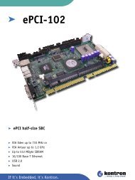
A typical configuration for a Kent Displays sign product conforms to the configuration outlined in Figure 2-<br />
1. For some display modules which have only one ChLCD display cell per module, the slave <strong>and</strong> master<br />
display are the same.<br />
Slave Display Module #1<br />
To Host<br />
Computer<br />
Serial Interface<br />
Master<br />
Display<br />
Module<br />
#1<br />
Slave Display Module #2<br />
Slave Display Module #N<br />
Slave Display Module #1<br />
Master<br />
Display<br />
Module<br />
#X<br />
Slave Display Module #2<br />
Figure 2-1: Typical Sign/Display Configuration<br />
Slave Display Module #N<br />
When Kent Display products are configured as outlined in Figure 2-1, the product contains the following<br />
features:<br />
St<strong>and</strong>ard Serial Communication Interface Description, © 1998-2002 Kent Displays Inc., doc. # 25016 Revision T, Page 3 of 52
St<strong>and</strong>ard Serial Interface Protocol Description<br />
! Several masters can be connected to a common serial communication interface controlled by the<br />
host computer. Each master can be assigned a unique address location to support a typical<br />
"hard-wired" multi-drop or wireless RF communication hardware configuration.<br />
! For sign display type modules, several slave display modules can be connected to a common<br />
master assembly. The image on each slave module along with each master display can be<br />
addressed <strong>and</strong> altered individually.<br />
! The modules contain all the high voltage electronics required to create the appropriate drive<br />
signals required for the ChLCD technology. This feature enables a simple asynchronous serial<br />
communication link for interfacing <strong>and</strong> controlling each module. Communication to the master<br />
modules can also be performed using an inexpensive, RF type, wireless link, available from Kent<br />
Displays.<br />
! The master module contains temperature compensation circuitry <strong>and</strong> firmware to enable the<br />
displays to be operated between ambient temperatures of 0º <strong>and</strong> 60º-70º C (upper temperature<br />
limit is dependent upon the display module type). This sophisticated logic enables this function to<br />
be transparent for the user. The display modules can also operate below 0º C, however the<br />
image update duration will be slower.<br />
! The user interface dictates the image content for each display module by downloading bitmapped<br />
image data or text character information to the master module. Due to the memory<br />
feature of the ChLCD technology, the last image written on a display module will remain<br />
indefinitely after a power interruption, unless the user requests a new image after power is<br />
restored. Each master unit can store several images or display messages for each slave display<br />
within the RAM of the master controller.<br />
3.0 Interface or Communication Protocol Description<br />
The Kent Displays st<strong>and</strong>ard serial communication protocol is designed to support typical half-duplex<br />
multi-drop, or unidirectional "simplex" configurations. The protocol can also be implemented using full<br />
duplex hardware components. The message packet formats are intended to provide all the necessary<br />
information for checking data integrity in the event data is corrupted due to a communication median<br />
failure. The protocol is designed for the host computer to act as a master, with the display modules<br />
acting as slaves.<br />
4.0 Lower Level Communication Protocol Description<br />
The following sub-sections outline the lower layers of the protocol, which determine the framing of the<br />
application layer data into message packets. The lower level communication protocol is common<br />
regardless of the Kent Displays sign or display product.<br />
4.1 Host Comm<strong>and</strong> Format to the Master Display Modules<br />
The messages sent by the host computer to the master display modules obey the following data packet<br />
format:<br />
St<strong>and</strong>ard Serial Communication Interface Description, © 1998-2002 Kent Displays Inc., doc. # 25016 Revision T, Page 4 of 52
St<strong>and</strong>ard Serial Interface Protocol Description<br />
Field<br />
Description<br />
Packet<br />
Field #<br />
Byte Count<br />
/ Field<br />
Table 4.1.1<br />
Packet<br />
Start<br />
Byte<br />
Master<br />
Address<br />
#<br />
Packet<br />
#<br />
Application<br />
Layer<br />
Comm<strong>and</strong><br />
Designation<br />
Application<br />
Layer<br />
Designation<br />
# 2.<br />
Application<br />
Layer Data<br />
Elements<br />
Packet<br />
Checksum<br />
Carriage<br />
Return<br />
1 2 3 4 5 6 7 8 9<br />
1 1 1 1 0-X 0-X 1 1 1<br />
Host Comm<strong>and</strong> Message Packet Format<br />
Line<br />
Feed<br />
Where:<br />
1. Packet Start Indication Byte = ASCII escape (ESC) byte; 1B (Hex). This field occupies a 1 byte<br />
width.<br />
2. Master Address # = Address setting of master display module, 0-31 (0-63 possibilities for most<br />
displays) decimal, or 0-1F (0-3F) Hexadecimal. Address #0 is typically allocated for broadcast<br />
message purposes, <strong>and</strong> should not be assigned to a sign location in normal operation. This field<br />
occupies a 1 byte width.<br />
3. Packet # = Packet number assigned by the host computer for the data packet, 0-255 possibilities.<br />
This field occupies a 1 byte width.<br />
4. Application Layer Comm<strong>and</strong> Designation = Dictates the action required for the master <strong>and</strong>/or<br />
slave display module. This field occupies a 1 byte width.<br />
5. Application Layer Designation #2 = This field is reserved as an additional designation for the<br />
application layer message content. Depending upon the display type, it may be used to<br />
designate the slave module number, it may designate the first <strong>and</strong> last bytes for loading bitmapped<br />
data, or it may be omitted from the message. This field a variable width field.<br />
6. Application Layer Data Elements = This field may contain additional data elements required for<br />
the application layer message content. Some messages will not require this field within the<br />
message data packet. This field a variable width field.<br />
7. Packet Checksum = Equals the least significant 8 bits of the summation of all elements contained<br />
in message packet fields 1-6. This field occupies a 1 byte width.<br />
8. Carriage return = ASCII carriage return, or 0D in hexadecimal. This field occupies a 1 byte width.<br />
9. Line feed = ASCII line Feed, or 0A in hexadecimal. This field occupies a 1 byte width.<br />
4.1.1 Additional Host Comm<strong>and</strong> Communication Requirements <strong>and</strong> RF Operation<br />
Most Kent display modules are designed to be battery operated. To enable battery operation, many Kent<br />
Display modules contain a "Wake-up <strong>and</strong> Sleep-mode" feature. To conserve battery power, these<br />
modules will power themselves down (or "Sleep") if inactivity is sensed locally on the diagnostic port(s)<br />
<strong>and</strong> if inactivity is sensed with the serial communication port. The display modules will automatically<br />
"power-up" or "Wake-up" when activity is sensed on either a local diagnostic or the serial communication<br />
port.<br />
If a host computer starts communicating with display modules connected to a multi-drop or RF wireless<br />
communication median, all modules connected to the multi-drop or in the proximity of the host computer<br />
(if RF link) will "Wake-up" <strong>and</strong> start normal operation. To ensure all modules connected to the multi-drop<br />
or in the proximity of the host "wake-up", the following actions need to be implemented by the host<br />
computer prior to transmitting normal message packets as described previously:<br />
1. The host should transmit a continuous stream of ASCII "U" (55 in hex) for approximately 1<br />
second (if communicating using a “hard-wired” RS-485 or RS-232 configuration, this 1 second<br />
duration needs only to be the length of time required to transmit a few characters).<br />
St<strong>and</strong>ard Serial Communication Interface Description, © 1998-2002 Kent Displays Inc., doc. # 25016 Revision T, Page 5 of 52
St<strong>and</strong>ard Serial Interface Protocol Description<br />
2. If the Kent Displays RF communication modules are used (Kent Display P/N’s 10158 <strong>and</strong> 10146),<br />
the duration for transmitting a continuous stream of ASCII “U” (55 in hex) should be extended<br />
from 1.0 to 5.0 seconds. The 5.0-second duration is required since the RF slave modules will<br />
only check the RF b<strong>and</strong> every 4.8 seconds, to conserve battery power. The 5.0-second duration<br />
is only necessary prior to the 1 st packet transmission. If a significant amount of data is to be sent<br />
<strong>and</strong> with significant pauses between each packet, then the host computer should turn OFF or<br />
disable the corresponding sign (or controller) sleep mode timer.<br />
3. The host should wait approximately 0.5 to 1 seconds after the wake-up transmission described<br />
previously to enable the sign master controllers to properly initialize.<br />
4. If the Kent Displays RF communication modules are used, then the host computer should send<br />
each packet with the following 4 byte sequence prior to field 1, or the ESC byte of the packet<br />
(illustrated in hexadecimal):<br />
0x00, 0xff, 0x00, 0xff<br />
Also, each packet should contain the following 2-byte sequence, after field 9, or the Line Feed of<br />
the packet (illustrated in hexadecimal):<br />
0x55, 0x00<br />
Neither the 4 byte, nor the 2 byte sequences indicated are included into the checksum calculation<br />
of the packet, installed in field 7 (refer to previous table). In an RF system, the 4 <strong>and</strong> 2 byte<br />
sequences are required to assist in synchronizing the RF slave <strong>and</strong> RF host bi-directional<br />
transceivers.<br />
The host will need to implement the 1 st three items above prior to transmitting normal message packets if<br />
any of the following conditions occur:<br />
a. The host computer is transmitting the first message packet for the given communication period.<br />
b. The host has not transmitted any type of message packet over the serial communication median<br />
for greater than preset “sleep mode” duration programmed into the sign or controller modules<br />
(typically 20 seconds).<br />
c. The host has physically moved to a new proximity for proper communication to other display<br />
modules (only applicable if using a wireless communication median).<br />
4.2 Sign Response Protocol Format to a Host Comm<strong>and</strong><br />
There are two possible responses that would be transmitted by the master display module to the host<br />
computer, a positive <strong>and</strong> a negative response. Both possibilities follow the same message packet format.<br />
If the host to master display module communication median is a Kent Displays supplied unidirectional RF<br />
communication link, the host computer will receive no responses from the display modules.<br />
The positive response format would appear as follows:<br />
Field Description ACK Packet # Packet<br />
Checksum<br />
Carriage<br />
Return<br />
Line<br />
Feed<br />
Packet Field # 1 2 3 4 5<br />
Byte #/ Field 1 1 1 1 1<br />
Table 4.2.1 Sign Positive Response Message Packet Format<br />
St<strong>and</strong>ard Serial Communication Interface Description, © 1998-2002 Kent Displays Inc., doc. # 25016 Revision T, Page 6 of 52
St<strong>and</strong>ard Serial Interface Protocol Description<br />
Where:<br />
1. ACK = ASCII acknowledgment character, 06 (Hex)<br />
2. Packet # = Packet number of the previously transmitted host message package, 0-255<br />
possibilities.<br />
3. Packet Checksum = Equals the least significant 8 bits of the summation of all elements contained<br />
in message packet fields 1 <strong>and</strong> 2.<br />
4. Carriage return = ASCII Carriage return, or 0D in hexadecimal.<br />
5. Line feed = ASCII line Feed, or 0A in hexadecimal.<br />
The negative response format would appear as follows:<br />
Where:<br />
Field Description NAK Packet # Packet<br />
Checksum<br />
Carriage<br />
Return<br />
Line<br />
Feed<br />
Packet Field # 1 2 3 4 5<br />
Byte #/ Field 1 1 1 1 1<br />
Table 4.2.2 Sign Negative Response Message Packet Format<br />
1. NAK = ASCII acknowledgment character, 15 (Hex)<br />
2. Packet # = Packet number of the previously transmitted host message package, 0-255<br />
possibilities.<br />
3. Packet Checksum = Equals the least significant 8 bits of the summation of all elements contained<br />
in message packet fields 1 <strong>and</strong> 2.<br />
4. Carriage return = ASCII carriage return, or 0D in hexadecimal.<br />
5. Line feed = ASCII line Feed, or 0A in hexadecimal.<br />
4.3 Host <strong>and</strong> Sign Module Communication Action Description<br />
A master sign/display module will respond to a host comm<strong>and</strong> if <strong>and</strong> only if the address within the host<br />
transmitted packet matches the hardware address setting on the respective sign module. A positive<br />
response will be sent if the host comm<strong>and</strong> packet is valid <strong>and</strong> the checksum received matches the<br />
checksum calculated by the master module controller. A negative response will be transmitted to the host<br />
if a checksum mismatch occurs due to a communication median problem, or if the host comm<strong>and</strong> was<br />
invalid.<br />
If a negative response or no response is received within 3 seconds after a host comm<strong>and</strong> is issued, the<br />
host should re-transmit the message packet to the sign or controller module. If after three consecutive<br />
unsuccessful host transmissions, the host computer should assume the respective sign module is "offline",<br />
<strong>and</strong> re-try communication at a later time.<br />
4.4 Broadcast Messages<br />
Broadcast messages are host transmitted messages where the host wants all signs or displays<br />
connected or in the proximity of the host (if the communication median is a wireless link) to implement the<br />
requested comm<strong>and</strong> within the message. Broadcast messages are typically used for less sophisticated<br />
type display systems where unique address capability is not required or for transmitting safety warning<br />
type messages, such as “Fire in Building, Please Evacuate”.<br />
Broadcast messages are the only type of messages where the signs do NOT transmit a response packet<br />
back to the host computer. If the host packet received at the sign is not corrupted (sign calculated<br />
St<strong>and</strong>ard Serial Communication Interface Description, © 1998-2002 Kent Displays Inc., doc. # 25016 Revision T, Page 7 of 52
St<strong>and</strong>ard Serial Interface Protocol Description<br />
checksum matches the checksum received in the packet), the sign will implement the requested<br />
comm<strong>and</strong> within the received packet.<br />
Address number 0 has been allocated for broadcast message purposes. Hence, the user should NOT<br />
select address 0 as an address location using the sign hardware components allocated for the selection.<br />
4.5 Sample Host Lower Level Communication Protocol Code<br />
The following code fragments illustrate how a host computer can implement the lower level data packing<br />
of application layer data <strong>and</strong> transmit the packets out of the host system. The function<br />
Get_Target_Response illustrates how a host system can check the packets received from a sign<br />
system. The following code fragments are written using a PC-based Visual Basic development system:<br />
Sub Lower_lev_pack_data ()<br />
' This function packs the data previously formatted & packed by the<br />
‘ Appl_level_pack_data subroutine.<br />
' The Appl_level_pack_data subroutine started the checksum calculation for<br />
‘ fields 4-6, while this function will add the remaining portions of<br />
' the fully packed message consisting of the following:<br />
' - The ESC character byte (field #1), 1B in Hex<br />
' - The Sign Address # in Hex (field #2).<br />
' - A message # used for tracking messages between this host & the respective<br />
‘ target. (field #3).<br />
' - The application level data stream created by a separate<br />
Appl_level_pack_data function (fields 4-6).<br />
' - A message checksum equaling the least significant 8 bits of all data<br />
‘ elements contained in fields 1-6. The checksum byte in packed into field 7..<br />
' - An ASCII carriage return (0D in hex) <strong>and</strong> Line feed (0A in hex) in fields 8 & 9).<br />
ESC = Chr$(27)<br />
sign_address_char = Chr$(address_index + 1)<br />
For Loc_Msg_num = New_msg_number_out To (New_msg_packed - 1)<br />
' Message fields #1-3<br />
temp = ESC & sign_address_char & Chr$(Loc_Msg_num)<br />
For p = 1 To 3<br />
' Add fields 1-3 to checksum calculation<br />
msg_byte = Mid(temp, p, 1)<br />
msg_check_sum(Loc_Msg_num) = msg_check_sum(Loc_Msg_num) + Asc(msg_byte)<br />
Next p<br />
' Mask off all bits except the least significant 8 bits for checksum<br />
checksum = msg_check_sum(Loc_Msg_num) And &HFF<br />
Complete_sign_msg_packet(Loc_Msg_num) = temp & Appl_lev_Msg_data(Loc_Msg_num) &<br />
Chr$(checksum) & Chr$(13) & Chr$(10)<br />
Next Loc_Msg_num<br />
End Sub<br />
Sub TX_new_Data_Packets ()<br />
' This function performs the actual transmission of data to the sign modules<br />
' after all the data has been packed by the appropriate aplication & lower level<br />
' packing routines. The function assumes all the appropriate flags have been<br />
' set by the lower level packing functions to determine which data packets need<br />
' tranmission. The function will clear the appropriate flags after the transmission<br />
' process has been completed.<br />
Label1.Visible = True<br />
For Loc_Msg_num = New_msg_number_out To (New_msg_packed - 1)<br />
' Message fields #1-3<br />
Label1.Caption = ""<br />
loop_count = 1<br />
packet_length = Len(Complete_sign_msg_packet(Loc_Msg_num))<br />
Do Until loop_count > 3<br />
Label1.Caption = "TX'ing Packet # " & Str$(Loc_Msg_num) & ", " &<br />
Mid(Complete_sign_msg_packet(Loc_Msg_num), 1, 10) & Chr$(10) & Chr(13)<br />
Label1.Caption = Label1.Caption & "To Sign # " & Str$(address_index + 1) & " Attempt # " &<br />
Str$(loop_count) & Chr$(10) & Chr$(13)<br />
Comm1.InBufferCount = 0 ' Discard any in RX buffer prior to this point<br />
' Perform the following setups prior to TX'ing data to minimize duration between TX & monitoring<br />
St<strong>and</strong>ard Serial Communication Interface Description, © 1998-2002 Kent Displays Inc., doc. # 25016 Revision T, Page 8 of 52
St<strong>and</strong>ard Serial Interface Protocol Description<br />
‘ Serial Port<br />
If rf_enabled_mnu.Checked = False Then<br />
Timer1.Enabled = False<br />
Timer1.Interval = Responce_TimeAllowed<br />
TimeOut1 = False<br />
Timer1.Enabled = True 'Enable after setting interval<br />
End If<br />
Screen.MousePointer = HOURGLASS ' Change pointer to hourglass.<br />
For i = 1 To packet_length<br />
' TX Out Msg Packet<br />
Comm1.Output = Mid(Complete_sign_msg_packet(Loc_Msg_num), i, 1)<br />
Next i<br />
If rf_enabled_mnu.Checked = False Then ' Hard wired communication configuration<br />
Target_Responce = Get_Target_Responce(Loc_Msg_num) ' Monitor RX Line<br />
If Target_Responce = True Then<br />
If comm_error = True Then ' Clear communication error message<br />
comm_error = False<br />
FormTitle<br />
End If<br />
Exit Do<br />
End If<br />
loop_count = loop_count + 1<br />
Else<br />
Exit Do<br />
End If<br />
If loop_count > 3 Then ' Display Communication Error Message<br />
comm_error = True<br />
FormTitle<br />
End If<br />
Loop<br />
Next Loc_Msg_num<br />
End Sub<br />
Function Get_Target_Responce (Msg_num)<br />
' This function monitors the RX port & analyses the responces from the<br />
' Target sign. If a valid message responce is received from the target,<br />
' (based on the TX'ed message information provided @ input parameters to<br />
' this function) a valid indication is returned to the calling context.<br />
'' If no responce or a NAK message is RX'ed, a Re-transmit message flag is<br />
' sent to the calling context to signal a re-transmission.<br />
c$ = Comm1.Input<br />
Get_Target_Responce = False<br />
field_pos = 1<br />
RX_checksum = 0<br />
type_msg_RXed = 0<br />
inform_user = False<br />
Do Until TimeOut1<br />
DoEvents<br />
If Not AOK Then Exit Do ' Allow User Abort<br />
If c$ "" Then<br />
If Asc(Mid(c$, 1, 1)) = 6 Then<br />
' ACK RX'ed<br />
If Asc(Mid(c$, 2, 1)) = Msg_num Then<br />
RX_checksum = 6 + Msg_num<br />
If Asc(Mid(c$, 3, 1)) = RX_checksum Then Get_Target_Responce = True<br />
Exit Do<br />
End If<br />
End If<br />
If Asc(Mid(c$, 1, 1)) = 21 Then ' NAK RX'ed<br />
If Asc(Mid(c$, 2, 1)) = Msg_num Then Exit Do<br />
End If<br />
Label1.Caption = Label1.Caption & "Character(s) RX'ed = " & c$ & " , # Char(s) RX'ed = " &<br />
Str(Len(c$)) '& Chr$(10) & Chr$(13)<br />
Else<br />
' No byte RX'ed from Serial Port<br />
If inform_user = False Then<br />
Label1.Caption = Label1.Caption & "Waiting for Sign # " & Str$(address_index + 1) & " to<br />
Respond to msg # " & Str$(Msg_num) & Chr$(10) & Chr$(13)<br />
inform_user = True<br />
End If<br />
End If<br />
c$ = Comm1.Input ' Monitor RX Port Again<br />
St<strong>and</strong>ard Serial Communication Interface Description, © 1998-2002 Kent Displays Inc., doc. # 25016 Revision T, Page 9 of 52
St<strong>and</strong>ard Serial Interface Protocol Description<br />
Loop<br />
Timer1.Enabled = False<br />
Screen.MousePointer = DEFAULT<br />
End Function<br />
' Return to normal<br />
5.0 Application Level Comm<strong>and</strong> Designations<br />
The following sub-sections outline all the possible application level comm<strong>and</strong>s available for the various<br />
Kent Displays sign <strong>and</strong> display products. This section will describe in detail the specific application level<br />
comm<strong>and</strong>s located in fields 4 through 6 outlined in table 4.1.1. All host to display product messages will<br />
be packed in the lower level formats described in section 4.1.<br />
All the responses generated by the Kent Displays modules <strong>and</strong>/or sign products will be identical to the<br />
format outlined in section 4.2.<br />
Since the format for the application level message fields are dependent upon the type of sign or display<br />
module, each of the following subsections is assigned to a specific display product.<br />
St<strong>and</strong>ard Serial Communication Interface Description, © 1998-2002 Kent Displays Inc., doc. # 25016 Revision T, Page 10 of 52
St<strong>and</strong>ard Serial Interface Protocol Description<br />
5.2 INFOSign II <strong>and</strong> III Host to Sign Application Level Comm<strong>and</strong> Descriptions (Mixed Mode)<br />
The following table outlines the available application level comm<strong>and</strong> sequences for the Kent Display<br />
INFOSign II <strong>and</strong> INFOSign III display modules. The following items pertain to the table:<br />
• Text enclosed in "", indicate the exact bytes (typically in ASCII, unless noted otherwise) to be<br />
output for the particular field. The application level comm<strong>and</strong> designations are case sensitive.<br />
• N/A designates that no bytes are designated or inserted for respective field.<br />
• Typical Data elements are illustrated for field #6.<br />
• First Pixel Byte address, Last Pixel Byte address are the respective address locations when the<br />
host is transmitting a binary image for a INFOSIGN display module.<br />
Many of the following comm<strong>and</strong>s are only available on INFOSign III products, <strong>and</strong> INFOSign II with<br />
revision H version firmware or later.<br />
# (Field #4) (Field #5) (Field #6)<br />
# Cmd.<br />
Designation<br />
Content<br />
Byte<br />
Count<br />
Typical Content<br />
1 "0"<br />
(ASCCI<br />
Zero)<br />
, ,<br />
<br />
2 "1" , ,<br />
<br />
3 "2" , ,<br />
(1-<br />
20 10), <br />
4 "3" , ,<br />
First Row # to Alter, Number<br />
of Rows Altered (20 10 Max),<br />
<br />
*5 "4" , ,<br />
(1-<br />
20 10), , ON Update<br />
Method, OFF Update<br />
Method, ,<br />
<br />
*6 "5" , ,<br />
First Row # to Alter,<br />
, Number of Rows<br />
Altered (20 10 Max), ON<br />
Update Method, OFF Update<br />
Method, ,<br />
<br />
7 “6” , < Message #>,<br />
First Row # to Alter, Non-<br />
Invert Duration (in 0.1<br />
increments), Invert Duration,<br />
# of Flash Cycles,<br />
<br />
3 DC2 DC4 “Disp 1 Msg 10<br />
Row 1” “Disp 1 Msg 10<br />
Row 2” <br />
3 (for full<br />
screen image)<br />
4 DC2 DC4 “Change Disp.1 Msg<br />
X Line 3” <br />
Byte<br />
Count<br />
5 Variable<br />
(600<br />
Bytes<br />
Max.)<br />
8 DC2 DC4 “Change Disp.1 Msg Variable<br />
X Line 3” <br />
9 Variable<br />
(600<br />
Bytes<br />
Max.)<br />
7 DC3 DC2 “Flash Disp.1 Msg X<br />
Row 4” <br />
Message Description<br />
Variable Load Text (image #1-4) into<br />
Memory (Does not display until<br />
valid “W” comm<strong>and</strong> received).<br />
900 Load Graphic (Image #1-4) data<br />
into (Does not display until valid<br />
“W” comm<strong>and</strong> received).<br />
Variable Load Partial Screen Text message<br />
in Memory to be updated in normal<br />
mode (Creates 1 line of Text on<br />
Display after corresponding “W”<br />
comm<strong>and</strong> is received).<br />
Variable<br />
(256<br />
Bytes<br />
Max.)<br />
Table 5.2.1: INFOSIGN Host to Display Application Level Comm<strong>and</strong>s ("Mixed Mode")<br />
Load Partial Screen graphic image<br />
in Memory to be output in Normal<br />
mode (Does not display until valid<br />
“W” comm<strong>and</strong> received).<br />
Load Partial Screen Text message<br />
in Memory to be Displayed in<br />
indicated Dynamic Update format<br />
(Creates 1 line of Text on Display<br />
after “W” comm<strong>and</strong> is received).<br />
Can not be used with 1-Line Fonts!<br />
Can only be implemented with<br />
INFOSign III type modules.<br />
Load Partial Screen Graphic<br />
image in Memory to be displayed<br />
in Dynamic Update format (Does<br />
Not display on ChLCD until after a<br />
“W” comm<strong>and</strong> is received). Can<br />
only be implemented with<br />
INFOSign III type modules.<br />
Load Partial Screen Text message<br />
(1 line of text) to be "Flashed" in<br />
the display as indicated in the<br />
corresponding parameters in field<br />
# 5 (Does Not flash on ChLCD<br />
display until after a “W” comm<strong>and</strong><br />
is received).<br />
St<strong>and</strong>ard Serial Communication Interface Description, © 1998-2002 Kent Displays Inc., doc. # 25016 Revision T, Page 11 of 52
St<strong>and</strong>ard Serial Interface Protocol Description<br />
8 "7" , ,<br />
<br />
9 "8" , Duration<br />
(Hex)<br />
10 "9" , , , <br />
3 N/A 0 Set/Clear Invert sense of Display<br />
image.<br />
2 N/A 0 Set Unique Pause Duration for<br />
respective message for Auto cycle<br />
operation (in 0.1 second<br />
increments).<br />
4 N/A 0 Start Automatic Image Cycling<br />
using the parameters specified.<br />
*11 ";" N/A 0 N/A 0 Ask Sign for display (Panel) Count.<br />
Host will receive message f/sign<br />
after positive response is received.<br />
12 "M” 1 N/A 0 Turn OFF/ON Sleep Timer (ON<br />
after reset or power-up)<br />
13 "O" N/A 0 N/A 0 Output ChLCD Temperature from<br />
Sign. Host will receive a<br />
Temperature message f/sign after<br />
positive response is received.<br />
14 "P" Duration (Hex) 1 N/A 0 Set Default Pause Duration<br />
between message writes, in 0.1<br />
second increments (25.5 sec.<br />
Duration maximum).<br />
15 "R” N/A 0 N/A 0 Reset Sign (Clears any data<br />
previously entered into the sign<br />
RAM).<br />
16 "S" N/A 0 N/A 0 Stop Automatic Message Cycling<br />
(Overrides any previous "t"<br />
comm<strong>and</strong>)<br />
17 “V” N/A 0 N/A 0 Sign Firmware ID Request. Host<br />
will receive a sign message after<br />
positive response is received.<br />
18 “W” 1 N/A 0 Display Message # X on Sign.<br />
19 "X" , <br />
2 N/A 0 Blank Display or panel #’s<br />
indicated.<br />
20 "Z" N/A 0 N/A 0 Turns OFF the Addressed<br />
Controller(s)<br />
NOTES: * - indicates comm<strong>and</strong> is only available in INFOSign III based products.<br />
Table 5.2.1: INFOSIGN Host to Display Application Level Comm<strong>and</strong>s (Continued)<br />
Where:<br />
1. = The message (or "Page" when using the INFOSoft) number, 1 thru the maximum<br />
# of messages for the sign (in hex) for the respective message packet. Refer to section 5.2.3<br />
for determining the maximum number of the messages which can be stored within a<br />
respective INFOSign master module.<br />
2. = bit mapped data for the respective INFOSIGN panel 30x240 "l<strong>and</strong>scape<br />
mode" image, starting from 1st row (top) left to 1st row (top) right, 2nd row left to 2nd row<br />
right, ...30th row left to 30th row right. In other words, bit 0 must be in bit 7 position, bit 1<br />
must be in bit 6 position, etc…<br />
3. ETX = End of Transmission Comm<strong>and</strong> byte (03 Hex). Indicates end of application layer message<br />
packet.<br />
4. = Indicates the number of image writes the display module is to generate<br />
before stopping. If the user provides a (Hex) into this respective location, the display<br />
module will assume the message cycling is to resume indefinitely, overriding the "sleepmode"<br />
feature of the display module (Not recommended for long term battery operation).<br />
5. = Off (non-inverted), <strong>and</strong> On (inverted)<br />
6. ON Update Method – Byte to indicate how the controller is to present the respective partial image<br />
or message. The following codes apply (Only available with INFOSign III based product):<br />
St<strong>and</strong>ard Serial Communication Interface Description, © 1998-2002 Kent Displays Inc., doc. # 25016 Revision T, Page 12 of 52
St<strong>and</strong>ard Serial Interface Protocol Description<br />
= “Wipe-ON” image presentation method (not valid for graphic messages). Characters<br />
within the image will appear to “grow” to the right as the text message is presented.<br />
Unlike the “Scroll-ON” method, characters to the left already presented in a previous<br />
frame will be stationary while new characters within the image are presented to the right.<br />
= “Scroll-ON” image presentation method (not valid for graphic messages). Characters<br />
within the image will appear to move to the left as the text message is presented. Unlike<br />
the “Wipe” update method, all the characters within the image will move until the final<br />
frame of the image is presented.<br />
= “Close-ON” image presentation method. This presentation method provides the<br />
illusion that the partial screen image is “sliding” down from the top <strong>and</strong> “sliding up from<br />
the bottom, until the final frame provides the completed image joined together.<br />
= “Open-ON” image presentation method. This presentation method provides the<br />
illusion that the partial screen image is “sliding” up <strong>and</strong> down from the center, until the<br />
final frame provides the completed image which has been completely “opened” from the<br />
center.<br />
= “Rotate-ON” image presentation method. This presentation method provides the<br />
illusion that the partial screen image is vertically rotating from the “Up-right” position, till it<br />
reaches an “Upside Down position”, then the frame sequence is reversed till the final<br />
frame of the “Up-right” position is reached.<br />
= "Swell-ON' image presentation method. This presentation method is used as an<br />
alternate method of generating a static frame of data. Unlike the previous methods<br />
where multiple frames are presented to the user, this method will only generate a single<br />
frame representative of the text or graphic data provided at the interface. This method<br />
will automatically use the “No OFF” OFF update method, outlined in the next bullet text.<br />
Unlike the "Fade-ON", this update method will erase the screen section prior (hence<br />
destroying the previous image) to generating the image in the cumulative drive method,<br />
hence creating an illusion that the new image will grow in brightness or "Swell" from a<br />
blank background during the update.<br />
= "Fade-ON" image presentation method. Like the "Swell-ON", this method is used as<br />
an alternate method of generating a static frame of data. This method will automatically<br />
use the “No OFF” OFF update method, outlined in the next bullet text. Unlike the "Swell-<br />
ON", this update method will NOT erase the screen section prior to generating the image<br />
in the cumulative drive method, hence creating an illustion that the new image section will<br />
start to appear as the previous image starts to disappear, hence the new image will<br />
appear to "Fade" over the previous.<br />
7. OFF Update Method – Byte to indicate how the controller is to remove the respective partial<br />
image or message. The following codes apply (Only available on INFOSign III based product):<br />
= “Wipe-OFF” image removal method (not valid for graphic messages). This removal<br />
method is the opposite of the “Wipe-ON” presentation method, with the characters being<br />
removed from right to left. The left-most character is the last character removed from the<br />
image area.<br />
= “Scroll-OFF” image removal method (not valid for graphic messages). This removal<br />
method is the same ast the “Scroll-ON” presentation method, with the characters being<br />
removed from right to left. The right-most character is the last character removed from<br />
the image area.<br />
= “Open-OFF” image removal method. This removal method is the opposite of the<br />
“Close-ON” presentation method, with the characters being removed from center towards<br />
the top <strong>and</strong> bottom edges of the image area. The middle-most rows of the image are the<br />
last portions removed from the image area.<br />
= “Close-OFF” image removal method. This removal method is the opposite of the<br />
“Open-ON” presentation method, with the characters being removed from the top <strong>and</strong><br />
bottom edges towards the center of the image area. The top <strong>and</strong> bottom rows of the<br />
image are the last portions removed from the image area.<br />
St<strong>and</strong>ard Serial Communication Interface Description, © 1998-2002 Kent Displays Inc., doc. # 25016 Revision T, Page 13 of 52
St<strong>and</strong>ard Serial Interface Protocol Description<br />
= “No OFF” image presentation method. This number will inform the respective<br />
controller to NOT remove the respective partial image after the respective pause duration<br />
has expired.<br />
8. - This single byte of data is bit-mapped to indicate the following<br />
features:<br />
• Bit 7 – Implements a “2x” horizontal image “Strech” feature if activated (set to 1). This<br />
feature is only valid for partial screen, "4" (for "Fades" <strong>and</strong> "Swells" only) <strong>and</strong> "6", single<br />
frame, text based comm<strong>and</strong>s. For instance, if implemented on a fixed distance 9 point line<br />
of text, the characters on the display will be twice as wide, <strong>and</strong> the maximum number of<br />
characters per text line (normally 30 for this font. Refer to next sub-section for explanation<br />
on font selection & control) will be half as much, or 15.<br />
• Bit 6 through 2 – Reserved for future use.<br />
• Bit 1 & 0 (L.S.B.) - Implements a vertical Height Multiplier (ie. A 10 row partial image would<br />
be output on 20 rows of the respective display if Height Multiplier is “2x”). 2 bits in this<br />
location will implement the function. Maximum multiplier is “3x”.<br />
00=1x (Normal, un-"Stretched")<br />
01=2x<br />
10=3x<br />
5.2.1 Special “0”, “2”, “4” <strong>and</strong> “6” Font Control Characters<br />
As indicated in the referenced comm<strong>and</strong> descriptions, the resident sign firmware has the capability to<br />
output text messages requested by the host computer. The host does not need to inform the display<br />
module which pixel to turn on or off to create a text character image. The sign modules also have the<br />
capability to output selected fonts <strong>and</strong> respond to font control characters. When the following special<br />
control characters (described in hexadecimal format within the "") are added within field 6 of the<br />
respective application layer messages, the following actions will occur (the following control characters<br />
must be the 1 st data elements entered in field #6):<br />
a) (VT) = Turn ON Tahoma 16 Single Line Font Control Character. All characters entered in<br />
field 6 after the reception of this control character will be output with the modified<br />
Tahoma 16 point one line per panel font format (Font can not be used with partial<br />
screen message format, “4” comm<strong>and</strong> designations).<br />
b) (HT) = Turn ON Times 16 Single Line Font Control Character. All characters entered in<br />
field 6 after the reception of this control character will be output with the modified<br />
Times Roman 16 point one line per panel font format (Font can not be used with<br />
partial screen message formats, or “2”, “4” or “6” comm<strong>and</strong> designations).<br />
c) (DC2) = Turn ON Dual Panel Font Control character. All characters entered in field 6 will<br />
be output in the 15 row (dual line) font format (two lines of text per INFOSIGN panel).<br />
A carriage return (0D in hexadecimal without a line feed) will need to be entered<br />
between the two lines of text. This is a ISO/IEC 8859-1 Compliant Font.<br />
d) (ENQ) = Turn ON 3-Line/Panel Font Control character. All characters entered in field 6 will<br />
be output in the 10 row (3 line) font format (three lines of text per INFOSIGN panel).<br />
A carriage return (0D in hexadecimal without a line feed) will need to be entered<br />
between the lines of text. This is a ISO/IEC 8859-1 Compliant Font.<br />
Notes: The absence of the above control characters will comm<strong>and</strong> the respective sign to output<br />
the respective panel in Letter Gothic 22 point; the default sign font (Font can not be<br />
used with partial screen message format, “4” comm<strong>and</strong> designations). This is a<br />
ISO/IEC 8859-1 Compliant Font<br />
e) (DC3) = Turn ON Underline control character. All characters entered in field 6 after the<br />
reception of this control character will be output in Underline format. The absence of<br />
St<strong>and</strong>ard Serial Communication Interface Description, © 1998-2002 Kent Displays Inc., doc. # 25016 Revision T, Page 14 of 52
St<strong>and</strong>ard Serial Interface Protocol Description<br />
this control character will comm<strong>and</strong> the respective sign to output the panel with the<br />
default non-underlined mode.<br />
5.2.2 Maximum Number of INFOSign Messages or Pages<br />
As indicated in the “” references in table 5.2.1, the INFOSign II (with revision H or later<br />
firmware) <strong>and</strong> INFOSign III products can store several messages or pages of data for the respective sign.<br />
To maximize the amount of messages to be stored in the INFOSign, the INFOSign uses a dynamic<br />
memory allocation method. Each message type assign for each panel with a given message (or “Page”)<br />
is allocated a fixed memory space, based on the message type for the given panel. The dynamic<br />
memory allocation firmware uses a “link list” to place each panel image in consecutive section of sign<br />
RAM memory.<br />
The following memory space allocations are assigned to the message types:<br />
# Mixed Mode Message Type Field #4<br />
Comm<strong>and</strong><br />
Designation(s)<br />
Fixed Memory<br />
Space Allocation<br />
1. Full Screen Text “0” 105 Bytes / Panel image<br />
2. Full Screen Graphic “1” 910 Bytes / Panel image<br />
3. Partial Screen Text, Dynamic “2”, “4” <strong>and</strong> “6” 43 Bytes / Panel image<br />
Update Text, Flashing Text<br />
4. Partial Screen Graphic, Dyanamic<br />
Update Partial Screen Graphic<br />
“3” <strong>and</strong> “5” 610 Bytes / Panel image<br />
Table 5.2.1: Sign Memory Space Allocations for INFOSign Message Data<br />
As indicated previously, the INFOSign will load panel message data into memory sequentially, into the<br />
next available memory location. Since the INFOSign has a finite amount of memory storage capacity, the<br />
interface software (“INFOSoft”, or equivalent) will need to either keep track of the amount of bytes used in<br />
the INFOSign to be sent to the respective INFOSign prior to transmitting, or the INFOSign will need to be<br />
“asked” the amount of available memory located for additional panel message storage. For instance, the<br />
maximum amount of message data that can be loaded into a 15153 INFOSign II master module, or a<br />
10060 INFOSign II controller module can not exceed 43,680 bytes. The INFOSign III controller module<br />
can store up to 46,117 bytes of message data.<br />
The following items pertain to maximizing the number of complete messages (or “pages”) stored by an<br />
INFOSign:<br />
1. Any two INFOSign master modules of the same type will have the same panel message storage<br />
capacity. However, an INFOSign containing only 4 display panels will be able to store more<br />
complete messages (or complete “pages”) than a sign containing 12 display panels. For<br />
instance, if data is loaded into an INFOSign II sign for each of its panels, the 12 panel sign will be<br />
able to store 4 full screen graphic images for each panel {12 [panels/message] x 910<br />
[bytes/panel] x 4 [messages] = 43,680 [bytes]}, whereas the 4 panel sign will be able to store 12<br />
full graphic images for each of its panels {4 [panels/message] x 910 [bytes/panel] x 12<br />
[messages] = 43,680 [bytes]}<br />
2. To maximize the number complete messages to be loaded into a sign, use text-based messages<br />
(full, partial or flashing) whenever possible. For instance, as illustrated in the previous bullet, a 12<br />
panel sign can store 4 complete full screen graphic messages, whereas the same sign can store<br />
34 complete full screen text based message {12 [panels/message] x 105 [bytes/panel] x 34<br />
[messages] = 42,840 [bytes], which is less than 43,680 [bytes]}.<br />
St<strong>and</strong>ard Serial Communication Interface Description, © 1998-2002 Kent Displays Inc., doc. # 25016 Revision T, Page 15 of 52
St<strong>and</strong>ard Serial Interface Protocol Description<br />
5.2.2.1 Controlling <strong>and</strong> Determining the Message Count<br />
The following application comm<strong>and</strong> are available to the mixed mode user to enable the interface to query<br />
(or “ask”) the INFOSign the amount of available RAM memory left for additional message storage, <strong>and</strong> to<br />
enable the user to clear existing memory in the event the INFOSign dynamic message storage algorithm<br />
becomes fragmented.<br />
# (Field #4) (Field #5) (Field #6)<br />
# Cmd. Content<br />
Byte Typical Byte Message Description<br />
Designation<br />
Count Content Count<br />
1 "Y" N/A 0 N/A 0 Output Mixed Mode Message storage availability<br />
from Sign. Host will receive message f/sign after<br />
positive response is received.<br />
2 “>”<br />
(3e in Hex)<br />
N/A 0 N/A 0 Clear All Previously Received Message Data<br />
(overides any previous Message trigger or<br />
Automatic cycle comm<strong>and</strong> received).<br />
Table 5.2.3.1: Additional INFOSIGN Memory Allocation/Query Comm<strong>and</strong>s<br />
As indicated from the table above, the interface will receive a message like the following example after<br />
the INFOSign receives a “Y” comm<strong>and</strong>:<br />
RAM Bytes Used = 0791<br />
RAM Bytes Available = A2AF<br />
RAM Fragmented = 0000<br />
The quantities provided on each line after the introductory text is output in ASCCI hexadecimal format.<br />
As illustrated in the example above, the given INFOSign currently has 0791 (1937 10 ) bytes occupied with<br />
user message data, has A2AF (41,647 10 ) bytes available for additional message storage, <strong>and</strong> has 0 bytes<br />
wasted due to fragmentation of the message data.<br />
On current INFOSign designs, message data fragmentation will only occur if the user changes an existing<br />
message (for a given message <strong>and</strong> panel number) from one mixed mode message type, to another as<br />
indicated in table 5.2.3. If the amount of RAM space, which is fragmented, becomes excessive, the user<br />
(or “interface”) may wish to output a “Clear All Previously Received Message Data” comm<strong>and</strong> (“>”<br />
comm<strong>and</strong>), followed by transmission of all the required data using the mixed mode comm<strong>and</strong>s indicated<br />
in table 5.2.2.<br />
Another good application of the “Clear All Previously Received Message Data” comm<strong>and</strong> (“>” comm<strong>and</strong>)<br />
is when the interface application starts a new transmission of data to an INFOSign, which may be in<br />
continuous automatic cycle mode. After the INFOSign receives the “>” comm<strong>and</strong>, the INFOSign will stop<br />
generation of any messages presently being driven onto the display panels, then clear memory allocated<br />
for message storage. After transmission of the “>” comm<strong>and</strong>, the interface should load new message<br />
data to the respective INFOSign master or controller module.<br />
5.3 QUAD Application Layer Com<strong>and</strong> Descriptions<br />
The following table outlines the available application level comm<strong>and</strong> sequences for the Kent Display new<br />
QUAD display modules. The following items pertain to the table:<br />
• Text enclosed in "", indicate the exact bytes (typically in ASCII, unless noted otherwise) to be<br />
output for the particular field. The application level comm<strong>and</strong> designations are case sensitive.<br />
• N/A designates that no bytes are designated or inserted for respective field.<br />
St<strong>and</strong>ard Serial Communication Interface Description, © 1998-2002 Kent Displays Inc., doc. # 25016 Revision T, Page 16 of 52
St<strong>and</strong>ard Serial Interface Protocol Description<br />
# (Field 4) (Field #5) (Field #6)<br />
# Cmd.<br />
Designation<br />
Content<br />
Byte<br />
Count<br />
Typical Content Byte<br />
Count<br />
% 1 "A" “Sign Row 1, Msg 1<br />
Text” EOT “Sign Row<br />
2, Msg 1 Text”<br />
% 2 "B" “Sign Row 1, Msg 2<br />
Text” EOT “Sign Row<br />
2, Msg 2 Text”<br />
% 3 "C" “Sign Row 1, Msg 3<br />
Text” EOT “Sign Row<br />
3, Msg 2 Text”<br />
% 4 "D" “Sign Row 1, Msg 4<br />
Text”, EOT DC1 DC3<br />
“Sign Row 2, Msg 4 Text”<br />
DC3 DC1<br />
% 5 "E" “Sign Row 1, Msg 5<br />
Text” EOT DC1 “Sign<br />
Row 2, Msg 5 Text” DC1<br />
% 6 "F" “Sign Row 1, Msg 6<br />
Text”, EOT DC3 “Sign<br />
Row 2, Msg 6 Text”<br />
DC3<br />
% 7 "G" “Sign Row 1, Msg 7<br />
Text” EOT DC1 “Sign<br />
Row 2, Msg 7 Text” DC1<br />
Variable<br />
(320 Max)<br />
Variable<br />
(320 Max)<br />
Variable<br />
(320 Max)<br />
Variable<br />
(320 Max)<br />
Variable<br />
(320 Max)<br />
Variable<br />
(320 Max)<br />
Variable<br />
(320 Max)<br />
% 8 "H" (8-23) 1 “Sign Row 1,<br />
Msg 8-23 Text”,<br />
EOT DC3 “Sign<br />
Row 2, Msg 8-23<br />
Text” DC3 ETX<br />
Message Description<br />
ETX 1 Load Text-based Sign message<br />
#1 into memory, <strong>and</strong> display on<br />
sign.<br />
ETX 1 Load Text-based Sign message<br />
#2 into memory, <strong>and</strong> display on<br />
sign.<br />
ETX 1 Load Text-based Sign message<br />
#3 into memory, <strong>and</strong> display on<br />
sign.<br />
ETX 1 Load Text-based Sign message<br />
#4 into memory, <strong>and</strong> display on<br />
sign.<br />
ETX 1 Load Text-based Sign message<br />
#5 into memory, <strong>and</strong> display on<br />
sign.<br />
ETX 1 Load Text-based Sign message<br />
#6 into memory, <strong>and</strong> display on<br />
sign.<br />
ETX 1 Load Text-based Sign message<br />
#7 into memory, <strong>and</strong> display on<br />
sign.<br />
Variable<br />
(320<br />
Max)<br />
Load Text-based Sign message<br />
#8, 9, .. or 23 into memory, <strong>and</strong><br />
display on sign.<br />
% 9 "I" N/A 0 N/A 0 Toggle the sense of image<br />
generation.<br />
10 "P" Duration (Hex) 1 N/A 0 Set Pause Duration between<br />
image writes, in 0.1 second<br />
increments (25.5 sec. Duration<br />
maximum).<br />
11 "O” N/A 0 N/A 0 Output ChLCD Temperature from<br />
Sign. Host will receive a 4 byte<br />
message f/sign after positive<br />
response is received.<br />
12 "R” N/A 0 N/A 0 Reset Sign (Clears any data<br />
previously entered into the sign<br />
RAM).<br />
13 "S" N/A 0 N/A 0 Stop Automatic Message Cycling<br />
(Overrides any previous "t"<br />
comm<strong>and</strong>)<br />
%<br />
14<br />
"T" ,<br />
<br />
2 ,<br />
<br />
Table 5.3.1A: Available Host Computer QUAD Application Layer Comm<strong>and</strong>s<br />
4 Start Automatic Message Cycling<br />
for messages indicated, the<br />
specified image sense, <strong>and</strong> the<br />
amount of cycles specified (all #’s<br />
in hex)<br />
St<strong>and</strong>ard Serial Communication Interface Description, © 1998-2002 Kent Displays Inc., doc. # 25016 Revision T, Page 17 of 52
St<strong>and</strong>ard Serial Interface Protocol Description<br />
# (Field 4) (Field #5) (Field #6)<br />
# Cmd. Content<br />
Byte Typical Content Byte Message Description<br />
Designation<br />
Count<br />
Count<br />
15 "U” 2 N/A 0 Inform Sign its configuration.<br />
<br />
16 "V” N/A 0 N/A 0 Sign Firmware ID Request.<br />
Host will receive a sign<br />
message after positive<br />
response is received.<br />
17 "W” 1 N/A 0 Display Message # X already<br />
loaded on Sign.<br />
18 "X" N/A 0 N/A 0 Blank Sign (all sign rows)<br />
* 19 “Y” , ,<br />
,<br />
<br />
4 Sign Row 1<br />
Text!, ETX<br />
Variable Load Text-based Sign<br />
message #X into memory.<br />
Does not display until “W”<br />
cmd. RX’ed.<br />
* 20 “Z” , , <br />
* 21 “>”<br />
(3e in Hex)<br />
3 N/A 0 Start Automatic Message<br />
Cycling for messages<br />
indicated, the amount of cycles<br />
specified (all #’s in hex)<br />
N/A 0 N/A 0 Clear All Previously Received<br />
Message Data (overides any<br />
previous Message trigger or<br />
Automatic cycle comm<strong>and</strong><br />
received).<br />
* Indicates Y & Z comm<strong>and</strong> are used together in place of A-H <strong>and</strong> T comm<strong>and</strong>s, <strong>and</strong> are only available on QUADs (along with “>”<br />
comm<strong>and</strong>) with 13028 Revision C firmware, or later.<br />
% indicates respective comm<strong>and</strong> should not be used for new designs. Y, Z & > comm<strong>and</strong> set should be used instead.<br />
Table 5.3.1B: Available Host Computer QUAD Application Layer Comm<strong>and</strong>s (Continued)<br />
Where:<br />
1. Text data for all rows of a sign are to be combined into a single application layer message packet,<br />
where:<br />
a. EOT = End of Sign Row Text Comm<strong>and</strong> byte (04 Hex). An EOT byte received without<br />
any prior text data will inform the respective sign that data elements for the respective<br />
sign row are not to be changed for the respective message #. The text data for the last<br />
row of the sign is not to be terminated with an EOT character.<br />
b. ETX = End of Transmission Comm<strong>and</strong> byte (03 Hex). Indicates end of application layer<br />
message packet.<br />
2. = Three consecutive bit mapped binary<br />
bytes indicating the sense of display messages (Normal mode = Reflective text/image with<br />
transparent background) 1 through 23. A "1" bit in the any of the following bit assignments<br />
for the 3 bytes will comm<strong>and</strong> the respective message into inverted mode (transparent<br />
text/image with reflective background):<br />
• Bit 7 (Left-most, or M.S.B.) - Message #1 (Msg_Sense Cmd_Byte1), Message #9<br />
(Msg_Sense Cmd_Byte2) & Message #17 (Msg_Sense Cmd_Byte3) image sense<br />
assignment.<br />
• Bit 6 - Message #2, Message #10 & Message #18 sense assignment.<br />
• Bit 5 - Message #3, Message #11 & Message #19 sense assignment.<br />
• Bit 4 - Message #4, Message #12 & Message #20 sense assignment.<br />
St<strong>and</strong>ard Serial Communication Interface Description, © 1998-2002 Kent Displays Inc., doc. # 25016 Revision T, Page 18 of 52
St<strong>and</strong>ard Serial Interface Protocol Description<br />
• Bit 3 - Message #5, Message #13 & Message #21 sense assignment.<br />
• Bit 2 - Message #6, Message #14 & Message #22 sense assignment.<br />
• Bit 1 - Message #7, Message #15 & Message #23 sense assignment.<br />
• Bit 0 (L.S.B.) - Message #7, Message #15 & Toggle message sense for all messages<br />
after each message cycle (Msg_Sense Cmd_Byte3). A 1 bit in this location will<br />
implement the function.<br />
3. = Indicates the number of image writes the display module is to generate<br />
before stopping. If the user provides a (Hex) into this respective location, the display<br />
module will assume the message cycling is to resume indefinitely, overriding the "sleepmode"<br />
feature of the display module (Not recommended for long term battery operation).<br />
4. < Invert Status> = Off (non-inverted), <strong>and</strong> On (inverted)<br />
5. - Normal, <strong>and</strong> Wipe (Note: Update methods must be common<br />
between rows within the same message or page number).<br />
5.3.1 Special "A" through "H" & “Y” Comm<strong>and</strong> Text Control Characters<br />
As implied in the "A" through "H" & “Y” comm<strong>and</strong> descriptions, the resident sign firmware has the<br />
capability to output text messages requested by the host computer. The host does not need to inform the<br />
display module which pixel to turn on or off to create a text character image. The sign modules also have<br />
the capability to change fonts <strong>and</strong> to "Underline" the host requested characters. When the following<br />
special control characters (described in hexadecimal format within the "") are added within field 6 of the<br />
"A" through "H" application layer messages, create the following actions:<br />
a) (DC1) = Toggle Font Control character. All characters entered in field 5 after the<br />
reception of this control character will have the opposite font available font than the<br />
characters preceding the character (The QUAD modules presently have 2 fonts<br />
available, Big ((Default)) <strong>and</strong> Courier-New 9 Pt.)<br />
b) (DC3) = Underline comm<strong>and</strong> toggle character. All characters entered in field 6 after the<br />
reception of this control character will have the opposite Underline characteristic than<br />
the characters preceding the character.<br />
c) The “Y” comm<strong>and</strong>s do not toggle the Control character. Instead, the Control character will<br />
inform the sign if the Font/Underline is on or off. If the Control character is present<br />
(prior to remaining field 6 characters), the Comm<strong>and</strong> is on.<br />
When the QUAD modules start outputting text characters dictated by a host "A" through “H” comm<strong>and</strong>s,<br />
the sign firmware will assume the requested characters are to be output in "NORMAL" text generation<br />
mode (Big font, not underlined).<br />
5.4 1/8 VGA Controller Host to Display Application Level Field Descriptions<br />
The following table outlines the available application level comm<strong>and</strong> sequences for the Kent Display 1/8<br />
VGA modules. The following items pertain to the table:<br />
• Text enclosed in "", indicate the exact bytes (typically in ASCII, unless noted otherwise) to be<br />
output for the particular field. Elements designated between < <strong>and</strong> > characters are to be<br />
output in binary. The application level comm<strong>and</strong> designations are case sensitive.<br />
• N/A designates that no bytes are designated or inserted for respective field.<br />
• Typical Data elements are illustrated for field #6.<br />
St<strong>and</strong>ard Serial Communication Interface Description, © 1998-2002 Kent Displays Inc., doc. # 25016 Revision T, Page 19 of 52
St<strong>and</strong>ard Serial Interface Protocol Description<br />
# (Field<br />
(Field #5) (Field #6)<br />
#4)<br />
# Cmd. Content<br />
Byte Typical Content Byte Count Message Description<br />
Designation<br />
Count<br />
1 "A" , <br />
*(1-1E Hex), <br />
3 DC1 DC4 “Disp 1 Msg 10<br />
Row 1” “Disp 1 Msg<br />
10 Row 2” <br />
Variable Load Full Screen Text *(image<br />
#1-30) message into Memory<br />
(Does not display after valid<br />
message RX’ed).<br />
2 “B” , <br />
*(1-0F Hex), <br />
3 “C”<br />
(reserved<br />
for future<br />
use)<br />
3 4800 Load Graphic *(Image #1-15)<br />
Data into memory (Does not<br />
display after valid message<br />
RX’ed).<br />
x <br />
Variable<br />
NOT IMPLEMENTED at this<br />
Time.<br />
4 “D” 1 N/A 0 Update Image from center out<br />
on/off (default is ON). This<br />
comm<strong>and</strong> does not apply <strong>and</strong><br />
is not implemented if using<br />
10120 controller module.<br />
5 “E” N/A 0 N/A 0 Turn the display OFF.<br />
**6 “F” , ,<br />
(1-<br />
155 10), , ON<br />
Update Method, OFF<br />
Update Method, , <br />
**7 “G” , ,<br />
First Row # to Alter,<br />
, Number of Rows<br />
Altered (16 10 Max), ON<br />
Update Method, OFF<br />
Update Method, , <br />
**8 “H” , < Message<br />
#>, First Row # to Alter,<br />
Non-Invert Duration (in 0.1<br />
increments), Invert<br />
Duration, # of Flash<br />
Cycles, Additional Future<br />
Parameter (1 byte not<br />
used)<br />
9 “I” , *(0-<br />
1E Hex), <br />
8 DC1 DC3 “Disp 1 Msg 10<br />
Row 1” <br />
Variable<br />
9 Variable<br />
(480 Max)<br />
7 DC1 DC3 “Flash Disp.1 Msg<br />
X Row 4” <br />
Variable<br />
(256 Bytes<br />
Max.)<br />
Load Partial Screen Text<br />
message in Memory to be<br />
Displayed in indicated<br />
Dynamic Update format<br />
(Creates 1 line of Text on<br />
Display after “W” comm<strong>and</strong> is<br />
received).<br />
Load Partial Screen Graphic<br />
image in Memory to be<br />
displayed in Dynamic Update<br />
format (Does Not display on<br />
ChLCD until after a “W”<br />
comm<strong>and</strong> is received).<br />
Load Partial Screen Text<br />
message (1 line of text) to be<br />
"Flashed" in the display as<br />
indicated in the corresponding<br />
parameters in field # 5 (Does<br />
Not flash on ChLCD display<br />
until after a “W” comm<strong>and</strong> is<br />
received).<br />
3 N/A 0 Invert sense of image (Img # 0<br />
is the Global sense for all<br />
images default is off)<br />
**10 "J" Duration (Hex) 1 N/A 0 Set Pause Duration between<br />
Auto cycle image writes, in 0.1<br />
second increments.<br />
**11 "K" , Duration (Hex) 2 N/A 0 Set Unique Pause Duration for<br />
Message or Image # indicated<br />
(in 0.1 second increments).<br />
12 “N” , ,<br />
(1-<br />
160 decimal), <br />
4 DC3 DC4 “Change Disp.1<br />
Msg X Row 4” <br />
Variable<br />
(27 Max if<br />
10072, <strong>and</strong><br />
50 if 10120<br />
controller).<br />
Change Partial Screen Text<br />
message in Memory (Creates<br />
1 line of Text in memory Does<br />
not display after valid message<br />
RX’ed).<br />
Table 5.4.1A: 1/8 VGA Controller Host to Display Application Level Comm<strong>and</strong>s<br />
* indicates no Fixed number of Images are required if using dynamic memory storage capability of 10120 controller module,<br />
hence number limitations indicated do not appply.<br />
** indicates application level comm<strong>and</strong> is only available with 10120 controller module.<br />
St<strong>and</strong>ard Serial Communication Interface Description, © 1998-2002 Kent Displays Inc., doc. # 25016 Revision T, Page 20 of 52
St<strong>and</strong>ard Serial Interface Protocol Description<br />
(Field 4) Designation #2<br />
(Field #5)<br />
Data Elements<br />
(Field #6)<br />
12 “O” N/A 0 N/A 0 Output ChLCD Temperature<br />
from Sign. (Host will receive a<br />
message f/sign after positive<br />
response is received)<br />
13 "P" Duration (Hex) 1 N/A 0 Set Pause Duration between<br />
Auto cycle image writes, in 1<br />
second increments (Use “J”<br />
comm<strong>and</strong> in place of this<br />
comm<strong>and</strong> if using 10120<br />
controller module).<br />
14 "Q" 1 N/A 0 State of sleep timer (default is<br />
ON after power-on or reset).<br />
15 "S" N/A 0 N/A 0 Stop Automatic Message<br />
Cycling<br />
16 "T" , , , , <br />
17 "U" , <br />
*(1-0F Hex), First<br />
Row # to Alter,<br />
Number of Rows<br />
Altered (88 Max.),<br />
<br />
5 N/A 0 Start Automatic Image Cycling<br />
using the parameters<br />
specified.<br />
5 Variable<br />
(2400 Bytes<br />
Max.)<br />
Change Graphic-based Partial<br />
Screen image in Memory<br />
(Does not display after valid<br />
message RX’ed).<br />
18 “V” N/A 0 N/A 0 Sign Firmware ID Request<br />
(Host will receive a sign<br />
message after positive<br />
response is received.<br />
19 “W” , <br />
2 N/A 0 Write the Image *(01 – 1E in<br />
hex) to the display<br />
20 "X" 1 N/A 0 Blank Display.<br />
* indicates no Fixed number of Images are required if using dynamic memory storage capability of 10120 controller module,<br />
hence number limitations indicated do not appply.<br />
Table 5.4.1B: 1/8 VGA Controller Host to Display Application Level Comm<strong>and</strong>s (Continued)<br />
Where:<br />
1. = The image number for the respective package. The controller can store up to 30<br />
images. The first 15 images can be either text or graphic type messages. Images 16-30 (10 - 1E<br />
Hex) can only be text-based images. These stated fixed number <strong>and</strong> image type limitations do<br />
NOT apply if using the 10120 controller module to drive the respective 1/8 VGA display (refer to<br />
the “Maximum Number of 1/8 VGA Images” sub-section within this section of the document for<br />
details).<br />
2. = , other values reserved for future use.<br />
3. = Bit mapped data arranged with the most significant bit representing the left<br />
most pixel for the given byte. The image is loaded with the display in l<strong>and</strong>scape mode, starting<br />
from the byte in the 1st row (top) right to 1st row (top) left, 2nd row right to 2nd row left, ...160th<br />
row right to 160th row left.<br />
If using the 10120 controller module, the same described image loading algorithm is used,<br />
however the data is loaded from left to right. Hence, image data is loaded with the display in<br />
l<strong>and</strong>scape mode, starting from the byte in the 1st row (top) left most position, to 1st row (top) right<br />
most posion (30 bytes later), 2nd row left to 2nd row right, ...160th row left to 160th row right.<br />
St<strong>and</strong>ard Serial Communication Interface Description, © 1998-2002 Kent Displays Inc., doc. # 25016 Revision T, Page 21 of 52
St<strong>and</strong>ard Serial Interface Protocol Description<br />
4. ETX = End of Transmission Comm<strong>and</strong> byte (03 Hex). Indicates end of application layer message<br />
packet.<br />
5. = Off<br />
On<br />
6. = First Row # of respective of 160x240 display to<br />
alter (1-160 decimal) <strong>and</strong> number of rows to alter. The byte count of pixelated data in field 6 of<br />
the “U” comm<strong>and</strong> must equal 40 times the Number of Rows Altered.<br />
7. < Sense> = Non-inverted<br />
Inverted<br />
8. = Indicates the number of image writes the display module is to generate<br />
before stopping. If the user provides a (Hex) into this respective location, the display<br />
module will assume the Image cycling is to resume indefinitely, overriding the "sleep-mode"<br />
feature of the display module (Not recommended for long term battery operation).<br />
9. , or = binary data (1 byte each) indicating their<br />
respective durations in 1 second increments (if using 10072 controller), or 0.1 second increments<br />
(if using the 10120 controller). A value of FF hex (255 decimal) would equate to a 255 second<br />
(10072 controller), or 25.5 second (10120 controller) duration.<br />
10. = (“Toggle Image Sence Byte”) indicates during an automatic cycle<br />
process, if the corresponding module is to toggle the image sense for all images when the<br />
requested messages are repeated.<br />
11. ON Update Method – Byte to indicate how the controller is to present the respective partial image<br />
or message. The following codes apply:<br />
= “Wipe-ON” image presentation method (not valid for graphic messages). Characters<br />
within the image will appear to “grow” to the right as the text message is presented.<br />
Unlike the “Scroll-ON” method, characters to the left already presented in a previous<br />
frame will be stationary while new characters within the image are presented to the right.<br />
= “Scroll-ON” image presentation method (not valid for graphic messages). Characters<br />
within the image will appear to move to the left as the text message is presented. Unlike<br />
the “Wipe” update method, all the characters within the image will move until the final<br />
frame of the image is presented.<br />
= “Close-ON” image presentation method. This presentation method provides the<br />
illusion that the partial screen image is “sliding” down from the top <strong>and</strong> “sliding up from<br />
the bottom, until the final frame provides the completed image joined together.<br />
= “Open-ON” image presentation method. This presentation method provides the<br />
illusion that the partial screen image is “sliding” up <strong>and</strong> down from the center, until the<br />
final frame provides the completed image which has been completely “opened” from the<br />
center.<br />
= “Rotate-ON” image presentation method. This presentation method provides the<br />
illusion that the partial screen image is vertically rotating from the “Up-right” position, till it<br />
reaches an “Upside Down position”, then the frame sequence is reversed till the final<br />
frame of the “Up-right” position is reached.<br />
= "Swell-ON' image presentation method. This presentation method is used as an<br />
alternate method of generating a static frame of data. Unlike the previous methods<br />
where multiple frames are presented to the user, this method will only generate a single<br />
frame representative of the text or graphic data provided at the interface (similiar to the<br />
normal partial screen message types). This method will automatically use the “No OFF”<br />
OFF update method, outlined in the next bullet text. Unlike the "Fade-ON", this update<br />
method will erase the screen section prior (hence destroying the previous image) to<br />
St<strong>and</strong>ard Serial Communication Interface Description, © 1998-2002 Kent Displays Inc., doc. # 25016 Revision T, Page 22 of 52
St<strong>and</strong>ard Serial Interface Protocol Description<br />
generating the image in the cumulative drive method, hence creating an illusion that the<br />
new image will grow in brightness or "Swell" from a blank background during the update.<br />
= "Fade-ON" image presentation method. Like the "Swell-ON", this method is used as<br />
an alternate method of generating a static frame of data. This method will automatically<br />
use the “No OFF” OFF update method, outlined in the next bullet text. Unlike the "Swell-<br />
ON", this update method will NOT erase the screen section prior to generating the image<br />
in the cumulative drive method, hence creating an illustion that the new image section will<br />
start to appear as the previous image starts to disappear, hence the new image will<br />
appear to "Fade" over the previous.<br />
12. OFF Update Method – Byte to indicate how the controller is to remove the respective partial<br />
image or message. The following codes apply:<br />
= “Wipe-OFF” image removal method (not valid for graphic messages). This removal<br />
method is the opposite of the “Wipe-ON” presentation method, with the characters being<br />
removed from right to left. The left-most character is the last character removed from the<br />
image area.<br />
= “Scroll-OFF” image removal method (not valid for graphic messages). This removal<br />
method is the same ast the “Scroll-ON” presentation method, with the characters being<br />
removed from right to left. The right-most character is the last character removed from<br />
the image area.<br />
= “Open-OFF” image removal method. This removal method is the opposite of the<br />
“Close-ON” presentation method, with the characters being removed from center towards<br />
the top <strong>and</strong> bottom edges of the image area. The middle-most rows of the image are the<br />
last portions removed from the image area.<br />
= “Close-OFF” image removal method. This removal method is the opposite of the<br />
“Open-ON” presentation method, with the characters being removed from the top <strong>and</strong><br />
bottom edges towards the center of the image area. The top <strong>and</strong> bottom rows of the<br />
image are the last portions removed from the image area.<br />
= “No OFF” image presentation method. This number will inform the respective<br />
controller to NOT remove the respective partial image after the respective pause duration<br />
has expired.<br />
13. - This single byte of data is bit-mapped to indicate the following<br />
features:<br />
• Bit 7 through 3 – Reserved for future use.<br />
• Bit 0 – Bit 2 - Implement a 1x to 8x Image height feature. For instance, a 10 row partial<br />
image would be output on 80 rows (or half the display) of the respective display if all 3<br />
bits are set high. The same 10 row image can be output on 40 rows of the display if bits<br />
0 <strong>and</strong> 1 are set high. Clearing all bits will output the image to the normal, 1x mode where<br />
the 10 row image will be output on 10 rows of the display.<br />
Note: Changing the contents of an image while writing the image to the screen may result in an<br />
undetermined image to be displayed.<br />
5.4.1 "A”, “N", “F” <strong>and</strong> “H” Comm<strong>and</strong> Text Control Characters<br />
As implied in the referenced comm<strong>and</strong> descriptions, the resident controller module firmware has the<br />
capability to output text Images requested by the host computer. The host does not need to inform the<br />
display module which pixel to turn on or off to create a text character image. The controller modules also<br />
have the capability to change fonts <strong>and</strong> respond to font control characters. When the following special<br />
control characters (described in hexadecimal format within the "") are added within field 6 of the "A”,<br />
“N”, “F” or “H” application layer comm<strong>and</strong>s, the following actions are implemented (the following control<br />
characters must be the 1 st data elements entered in field #6):<br />
St<strong>and</strong>ard Serial Communication Interface Description, © 1998-2002 Kent Displays Inc., doc. # 25016 Revision T, Page 23 of 52
St<strong>and</strong>ard Serial Interface Protocol Description<br />
16x30 Pixel Characters: Each of the following described font controls will occupy a 16x30 (columns x<br />
rows pixel space/character. Up to 15 characters/text line <strong>and</strong> up to 8 text lines/display image can be<br />
output using these font controls.<br />
a) (VT) = Turn ON Tahoma 16, 30 row Font Control Character. All characters entered in field<br />
6 after the reception of this control character will be output with the modified Tahoma<br />
16 point font format. A carriage return (0D in hexadecimal) will need to be entered<br />
between each text line if used with full screen text comm<strong>and</strong>.<br />
b) (HT) = Turn ON Times 16, 30 row Font Control Character. All characters entered in field 6<br />
after the reception of this control character will be output with the modified Times<br />
Roman 16 point font format. A carriage return (0D in hexadecimal) will need to be<br />
entered between each text line if used with full screen text comm<strong>and</strong>.<br />
10x15 Pixel Characters: The font control below will occupy a 10x15 (columns x rows) pixel<br />
space/character. Up to 24 characters/text line <strong>and</strong> up to 16 text lines/display image can be output<br />
using this font control.<br />
c) (DC2) = Turn ON Fixed Distance 11, 15 row Font Control character. All characters entered<br />
in field 6 will be output in the dual line font format. A carriage return (0D in<br />
hexadecimal) will need to be entered between each text line if used with full screen<br />
text comm<strong>and</strong>.<br />
8x10 Pixel Characters: The font control below will occupy a 8x10 (columns x rows) pixel<br />
space/character. Up to 30 characters/text line <strong>and</strong> up to 16 text lines/display image can be output<br />
using this font control (Only available with 10120 controller module).<br />
d) (DC2) = Turn ON Fixed Distance 9 point Font Control character. All characters entered in<br />
field 6 will be output in the Fixed distance 9 point font format. A carriage return (0D in<br />
hexadecimal without a line feed) will need to be entered between the consecutive<br />
lines of text if used for a full screen text comm<strong>and</strong>.<br />
6x8 Pixel (“5x7”) Characters: The font control below will occupy a 6x8 (columns x rows) pixel<br />
space/character. Up to 40 characters/text line <strong>and</strong> up to 20 text lines/display image can be output<br />
using this font control (Only available with 10120 controller module).<br />
e) (ENQ) = Turn ON 5x7 character Font Control characters. All characters entered in field 6<br />
will be output in this format after reception. A carriage return (0D in hexadecimal<br />
without a line feed) will need to be entered between the consecutive lines of text if<br />
used for a full screen text comm<strong>and</strong>.<br />
Note: The absence of the above control characters will comm<strong>and</strong> the respective controller to output the<br />
respective image in Letter Gothic 22 point, 16x30 row font; the default font.<br />
f) (DC3) = Turn ON Underline control character. All characters entered in field 6 after the<br />
reception of this control character will be output in Underline format. The absence of<br />
this control character will comm<strong>and</strong> the respective sign to output the image with the<br />
default non-underlined mode.<br />
g) (DC4) = Turn ON Italicized control character. All characters entered in field 6 after the<br />
reception of this control character will be output in Italicized format. The absence of<br />
this control character will comm<strong>and</strong> the respective sign to output the image with the<br />
default non-Italicized mode. Italicized font controls are NOT supported by 10120<br />
controller module.<br />
St<strong>and</strong>ard Serial Communication Interface Description, © 1998-2002 Kent Displays Inc., doc. # 25016 Revision T, Page 24 of 52
St<strong>and</strong>ard Serial Interface Protocol Description<br />
5.4.2 1/8 Controller Response Protocol (10072 Controller Only)<br />
The 1/8 VGA controller responds to Images the same as in section 4.2 accept the negative response<br />
contains an added byte (Error Code) to report the reason the Image received a negative response.<br />
The negative response format would appear as follows:<br />
Field<br />
Description<br />
Packet<br />
Field #<br />
Byte #/<br />
Field<br />
NAK Message<br />
#<br />
Error Code Message<br />
Checksum<br />
Carriage<br />
Return<br />
Line<br />
Feed<br />
1 2 3 4 5 6<br />
1 1 1 1 1 1<br />
Table 5.4.2<br />
Where:<br />
1/8 Controller Negative Response Message Packet Format<br />
1. NAK = ASCII acknowledgment character; 15 (Hex)<br />
2. Message # = Message number of the previously transmitted host message package, 0-255<br />
possibilities.<br />
3. Error Code = Checksum error<br />
Buffer full<br />
controller busy<br />
reserved for debugging <strong>and</strong> future use.<br />
4. Message Checksum = Equals the least significant 8 bits of the summation of all elements<br />
contained in message packet fields 1 <strong>and</strong> 2.<br />
5. Carriage return = ASCII carriage return, or 0D in hexadecimal.<br />
6. Line feed = ASCII line Feed, or 0A in hexadecimal.<br />
5.4.3 Maximum Number of 1/8 VGA Image Storage Capacity (10120 Controller Only)<br />
As indicated in the “” references in table 5.4.1, the 1/8 VGA 10120 controller module can store<br />
several images, messages or pages of data for the respective display number assigned to the controller<br />
module. To maximize the amount of messages to be stored in the controller module, the controller uses<br />
a dynamic memory allocation method. Each message type for each display within a given message (or<br />
“Page”) is allocated a fixed memory space, based on the message type for the given display. The<br />
dynamic memory allocation firmware uses a “link list” to place each display image in consecutive section<br />
of the controller RAM memory.<br />
The following memory space allocations are assigned to the available message types:<br />
# Message Type Field #4 Comm<strong>and</strong><br />
Designation(s)<br />
Fixed Memory<br />
Space Allocation<br />
1. Full Screen Text “A” 833 Bytes / Display image<br />
2. Full Screen Graphic “B” 4814 Bytes / Display image<br />
3. Partial Screen Text, Dynamic “N”, “F” <strong>and</strong> “H” 55 Bytes / Display image<br />
Update Text, Flashing Text<br />
4. Partial Screen Graphic “U” 3014 Bytes / Display image<br />
5 Dyanamic Update Partial Screen<br />
Graphic<br />
“G”<br />
494 Bytes / Display image<br />
Table 5.4.3: Controller Memory Space Allocations for Different Types of Message Data<br />
St<strong>and</strong>ard Serial Communication Interface Description, © 1998-2002 Kent Displays Inc., doc. # 25016 Revision T, Page 25 of 52
St<strong>and</strong>ard Serial Interface Protocol Description<br />
As indicated previously, the 10120, 1/8 VGA controller module will load display image data into memory<br />
sequentially, into the next available memory location. Since the controller has a finite amount of memory<br />
storage capacity, the interface software (“1/8VGASoft”, or equivalent) will need to either keep track of the<br />
amount of bytes used in the respective controller address prior to transmitting, or the controller will need<br />
to be “asked” the amount of available memory for an additional display message storage. For instance,<br />
the maximum amount of message data that can be loaded into a 1/8 VGA controller can not exceed<br />
43,817 bytes.<br />
The following items pertain to maximizing the number of complete messages stored by a 1/8 VGA, 10120<br />
controller module:<br />
o To maximize the number complete messages to be loaded into a controller module, use textbased<br />
messages (full, partial, flashing or partial screen text dynamic update) whenever possible.<br />
For instance, the 1/8 VGA controller can store only 9 complete full screen graphic messages<br />
{4814 [bytes/message] x 9 [messages] = 43,326 [bytes]}, whereas the same controller can store<br />
52 complete full screen text based message {833 [bytes/message] x 52 [messages] = 43,316<br />
[bytes]}, which is less than the 43,817 bytes capacity. Additional message storage capacity can<br />
be obtained if partial screen text images are used whenever possible.<br />
5.4.3.1 Controlling <strong>and</strong> Determining the Message Count (10120 Controller Only)<br />
The following application comm<strong>and</strong>s are available to the user to enable the interface to query (or “ask”)<br />
the 1/8 VGA controller the amount of available RAM memory left for additional message storage, <strong>and</strong> to<br />
enable the user to clear existing memory in the event the controller dynamic message storage algorithm<br />
becomes fragmented.<br />
# (Field #4) (Field #5) (Field #6)<br />
# Cmd. Content<br />
Byte Typical Byte Message Description<br />
Designation<br />
Count Content Count<br />
1 "M" N/A 0 N/A 0 Output "M"essage storage availability from<br />
controller. Host will receive message f/controller<br />
after positive response is received.<br />
2 “>”<br />
(3e in Hex)<br />
N/A 0 N/A 0 Clear All Previously Received Message Data<br />
(overides any previous Message trigger or<br />
Automatic cycle comm<strong>and</strong> received).<br />
Table 5.4.4: Additional Controller Memory Allocation/Query Comm<strong>and</strong>s<br />
As indicated from the table above, the interface will receive a message like the following example after<br />
the 320x80 controller receives a “M” comm<strong>and</strong>:<br />
RAM Bytes Used = 0791<br />
RAM Bytes Available = A398<br />
RAM Fragmented = 0000<br />
The quantities provided on each line after the introductory text is output in ASCCI hexadecimal format.<br />
As illustrated in the example above, the given 1/8 VGA controller currently has 0791 (1937 10 ) bytes<br />
occupied with user message data, has A398 (41,880 10 ) bytes available for additional message storage,<br />
<strong>and</strong> has 0 bytes wasted due to fragmentation of the message data.<br />
On current 1/8 VGA controller designs, message data fragmentation will only occur if the user changes an<br />
existing message (for a given message <strong>and</strong> display number) from one message type, to another as<br />
indicated in table 5.4.3. If the amount of RAM space, which is fragmented, becomes excessive, the user<br />
(or the “interface”) may wish to output a “Clear All Previously Received Message Data” comm<strong>and</strong> (“>”<br />
St<strong>and</strong>ard Serial Communication Interface Description, © 1998-2002 Kent Displays Inc., doc. # 25016 Revision T, Page 26 of 52
St<strong>and</strong>ard Serial Interface Protocol Description<br />
comm<strong>and</strong>), followed by transmission of all the required message data using the comm<strong>and</strong>s indicated in<br />
the previous table.<br />
Another good application of the “Clear All Previously Received Message Data” comm<strong>and</strong> (“>” comm<strong>and</strong>)<br />
is when the interface application starts a new transmission of data to an 1/8 VGA controller, which may be<br />
in continuous automatic cycle mode. After the controller receives the “>” comm<strong>and</strong>, the controller will<br />
stop generation of any messages presently being driven onto the displays, then clear memory allocated<br />
for message storage. After transmission of the “>” comm<strong>and</strong>, the interface should load new message<br />
data to the respective controller module.<br />
5.5 128x32 Display Application Level Field Descriptions<br />
The following table outlines the available application level comm<strong>and</strong> sequences for the Kent Displays<br />
128x32 display modules. The following items pertain to the table:<br />
• Text enclosed in "", indicate the exact bytes (typically in ASCII, unless noted otherwise) to be<br />
output for the particular field. Elements designated between < <strong>and</strong> > characters are to be<br />
output in binary or Hexidecimal. The application level comm<strong>and</strong> designations are case<br />
sensitive (field #4).<br />
• N/A designates that no bytes are designated or inserted for respective field.<br />
• Typical Data elements are illustrated for field #6.<br />
St<strong>and</strong>ard Serial Communication Interface Description, © 1998-2002 Kent Displays Inc., doc. # 25016 Revision T, Page 27 of 52
St<strong>and</strong>ard Serial Interface Protocol Description<br />
# (Field #4) (Field #5) (Field #6)<br />
# Cmd.<br />
Designation<br />
Content<br />
Byte<br />
Count<br />
Typical Content<br />
1 "A" , (1-48),<br />
, <br />
2 "B" , (1-48),<br />
, <br />
3 "C" , , (1-25 10),<br />
, <br />
4 "D" , (1-48),<br />
First Row # to Alter, Number of<br />
Rows Altered (32 10 Max),<br />
, <br />
5 "E" , , (1-24 decimal),<br />
, ON Update Method,<br />
OFF Update Method, , <br />
6 “F” , , First Row<br />
# to Alter, , Number of<br />
Rows Altered (16 10 Max), ON<br />
Update Method, OFF Update<br />
Method, ,<br />
<br />
7 “G” , , First Row<br />
# to Alter, Non-Invert Duration (in<br />
0.1 increments), Invert Duration,<br />
# of Flash Cycles, Additional<br />
Future Parameter (1 byte not<br />
used)<br />
4 DC1 DC4 “Disp 1 Msg 10<br />
Row 1” “Disp 1 Msg 10<br />
Row 2” <br />
4 (for full<br />
screen image)<br />
5 DC3 DC4 “Change Disp.1 Msg<br />
X Row 4” <br />
Byte<br />
Count<br />
6 Variable<br />
(512<br />
Bytes<br />
Max.)<br />
8 DC3 DC4 “Change Disp.1 Msg Variable<br />
X Row 4” <br />
9 Variable<br />
(256<br />
Bytes<br />
Max.)<br />
Message Description<br />
Variable Load Text (image #1-48) into<br />
Memory (Does not display until<br />
valid “W” comm<strong>and</strong> received).<br />
512 Load Graphic (Image #1-48) data<br />
into (Does not display until valid<br />
“W” comm<strong>and</strong> received).<br />
Variable Load Partial Screen Text message<br />
in Memory to be updated in normal<br />
mode (Creates 1 line of Text on<br />
Display after corresponding “W”<br />
comm<strong>and</strong> is received).<br />
Change Graphic Partial Screen<br />
image in Memory to be output in<br />
“Shutter” mode (Does not display<br />
until valid “W” comm<strong>and</strong> received).<br />
Load Partial Screen Text message<br />
in Memory to be Displayed in<br />
indicated Dynamic Update format<br />
(Creates 1 line of Text on Display<br />
after “W” comm<strong>and</strong> is received).<br />
Can NOT be used for large Fonts!<br />
Load Partial Screen Graphic<br />
image in Memory in indicated<br />
Dynamic Update format (Does Not<br />
display on ChLCD until after a “W”<br />
comm<strong>and</strong> is received).<br />
7 DC3 DC4 “Flash Disp.1 Msg X<br />
Row 4” <br />
Variable<br />
(256<br />
Bytes<br />
Max.)<br />
Load Partial Screen Text message<br />
to be "Flashed" in the display as<br />
indicated in the corresponding<br />
parameters in field # 5/ (Does Not<br />
flash on ChLCD display until after<br />
a “W” comm<strong>and</strong> is received).<br />
8 “H” N/A 0 N/A 0 Turns OFF the display(s) off.<br />
9 "I" , (1-30<br />
Hex), <br />
3 N/A 0 Invert sense of image (Img # 0 is<br />
the Global sense for all images.<br />
Default is non-Invert state)<br />
10 “O” N/A 0 N/A 0 Output ChLCD Temperature from<br />
Sign. (Host will receive a message<br />
f/sign after positive response is<br />
received)<br />
11 "P" Duration (Hex) 1 N/A 0 Set Global Pause Duration<br />
between Auto cycle image writes,<br />
in 0.1 second increments.<br />
12 "Q" 1 N/A 0 State of sleep timer (default is on<br />
after power-on or reset).<br />
13 "S" N/A 0 N/A 0 Stop Automatic Message Cycling<br />
14 "T" , , , ,<br />
<br />
5 N/A 0 Start Automatic Image Cycling<br />
using the parameters specified.<br />
15 "U" 1 N/A 0 Ouput (Default or Custom) Image<br />
Sequence stored in ROM<br />
16 “V” N/A 0 N/A 0 Sign Firmware ID Request (Host<br />
will receive a sign message after<br />
positive response is received.<br />
17 “W” , 2 N/A 0 Write full, Partial, Dynamic or<br />
Flashing Image (1 - 48) to the<br />
selected display(s).<br />
18 "X" 1 N/A 0 Blank Display(s).<br />
Table 5.5.1: 128x32 Display Controller Host to Display Application Level Comm<strong>and</strong>s<br />
St<strong>and</strong>ard Serial Communication Interface Description, © 1998-2002 Kent Displays Inc., doc. # 25016 Revision T, Page 28 of 52
St<strong>and</strong>ard Serial Interface Protocol Description<br />
Where:<br />
6. = The image number for the respective package. The controller can store up to<br />
48 text, graphic full or partial screen images. for each of the possible 2 displays/controller.<br />
7. = for front display, for back display or for both.<br />
8. = Bit mapped data arranged with the most significant bit representing the<br />
left most pixel for the given byte. The image is loaded with the display in l<strong>and</strong>scape mode,<br />
starting from the first byte in the 1st row (top) left to 1st row (top) right, 2nd row left to 2nd row<br />
right, ...32 nd row right to 32 nd row left. If interfacing to a 15240 display module, all bytes of<br />
data entered are to be mirrored (bit 0 placed in bit 7 position, bit 1 placed in bit 6 position,<br />
ect..). If interfacing to any other 128x32 display type (i.e. 15373 or 128x32 display with the<br />
“ZIF” header), the data entered is NOT mirrored.<br />
9. ETX = End of Transmission Comm<strong>and</strong> byte (03 Hex). Indicates end of application layer<br />
message packet.<br />
10. = Off, On<br />
11. = First Row # of respective of 128x32 display<br />
to alter (1-32 decimal) <strong>and</strong> number of rows to alter. The byte count of pixelated data in field 6<br />
of the “D” & “F” comm<strong>and</strong> must equal 16 times the Number of Rows Altered.<br />
12. < Sense> = Image Sense, Non-inverted, Inverted.<br />
13. ON Update Method – Byte to indicate how the controller is to present the respective partial<br />
image or message. The following codes apply:<br />
= “Wipe-ON” image presentation method (not valid for graphic “F” comm<strong>and</strong><br />
messages). Characters within the image will appear to “grow” to the right as the text<br />
message is presented. Unlike the “Scroll-ON” method, characters to the left already<br />
presented in a previous frame will be stationary while new characters within the image<br />
are presented to the right.<br />
= “Scroll-ON” image presentation method (not valid for graphic “F” comm<strong>and</strong><br />
messages). Characters within the image will appear to move to the left as the text<br />
message is presented. Unlike the “Wipe” update method, all the characters within the<br />
image will move until the final frame of the image is presented.<br />
= “Close-ON” image presentation method. This presentation method provides the<br />
illusion that the partial screen image is “sliding” down from the top <strong>and</strong> “sliding up from<br />
the bottom, until the final frame provides the completed image joined together.<br />
= “Open-ON” image presentation method. This presentation method provides the<br />
illusion that the partial screen image is “sliding” up <strong>and</strong> down from the center, until the<br />
final frame provides the completed image which has been completely “opened” from the<br />
center.<br />
= “Rotate-ON” image presentation method. This presentation method provides the<br />
illusion that the partial screen image is vertically rotating from the “Up-right” position, till it<br />
reaches an “Upside Down position”, then the frame sequence is reversed till the final<br />
frame of the “Up-right” position is reached.<br />
= "Swell-ON' image presentation method (Only available on 10120 controller modules<br />
w/ revision E firmware, or later). This presentation method is used as an alternate<br />
method of generating a static frame of data. Unlike the previous methods where multiple<br />
frames are presented to the user, this method will only generate a single frame<br />
representative of the text or graphic data provided at the interface (similar to the "A" - "D"<br />
comm<strong>and</strong>s). This method will automatically use the “No OFF” OFF update method,<br />
outlined in the next bullet text. Unlike the "Fade-ON", this update method will erase the<br />
screen section prior (hence destroying the previous image) to generating the image in the<br />
cumulative drive method, hence creating an illusion that the new image will grow in<br />
brightness or "Swell" from a blank background during the update.<br />
= "Fade-ON" image presentation method (Only available on 10120 controller modules<br />
w/ revision E firmware, or later). Like the "Swell-ON", this method is used as an alternate<br />
method of generating a static frame of data. This method will automatically use the “No<br />
OFF” OFF update method, outlined in the next bullet text. Unlike the "Swell-ON", this<br />
St<strong>and</strong>ard Serial Communication Interface Description, © 1998-2002 Kent Displays Inc., doc. # 25016 Revision T, Page 29 of 52
St<strong>and</strong>ard Serial Interface Protocol Description<br />
update method will NOT erase the screen section prior to generating the image in the<br />
cumulative drive method, hence creating an illusion that the new image section will start<br />
to appear as the previous image starts to disappear; hence the new image will appear to<br />
"Fade" over the previous.<br />
14. OFF Update Method – Byte to indicate how the controller is to remove the respective partial<br />
image or message. The following codes apply:<br />
= “Wipe-OFF” image removal method (not valid for graphic “F” comm<strong>and</strong> messages).<br />
This removal method is the opposite of the “Wipe-ON” presentation method, with the<br />
characters being removed from right to left. The left-most character is the last character<br />
removed from the image area.<br />
= “Scroll-OFF” image removal method (not valid for graphic “F” comm<strong>and</strong> messages).<br />
This removal method is the same ast the “Scroll-ON” presentation method, with the<br />
characters being removed from right to left. The right-most character is the last character<br />
removed from the image area.<br />
= “Open-OFF” image removal method. This removal method is the opposite of the<br />
“Close-ON” presentation method, with the characters being removed from center towards<br />
the top <strong>and</strong> bottom edges of the image area. The middle-most rows of the image are the<br />
last portions removed from the image area.<br />
= “Close-OFF” image removal method. This removal method is the opposite of the<br />
“Open-ON” presentation method, with the characters being removed from the top <strong>and</strong><br />
bottom edges towards the center of the image area. The top <strong>and</strong> bottom rows of the<br />
image are the last portions removed from the image area.<br />
= “No OFF” image presentation method. This number will inform the respective<br />
controller to NOT remove the respective partial image after the respective pause duration<br />
has expired.<br />
15. = Indicates the number of image writes the display module is to generate<br />
before stopping. If the user provides a (Hex) into this respective location, the display<br />
module will assume the Image cycling is to resume indefinitely, overriding the "sleep-mode"<br />
feature of the display module (Not recommended for long term battery operation).<br />
16. = (Gobal used in “P” comm<strong>and</strong>) binary data (1 byte each)<br />
indicating their respective durations in 0.1 second increments. A value of FF hex (255<br />
decimal) would equate to a 25.5 second duration.<br />
17. = (“Toggle Image Sence Byte”) indicates during an automatic cycle<br />
process, if the corresponding module is to toggle the image sense for all images when the<br />
requested messages are repeated. This byte follows the stated Off, On hex<br />
format.<br />
18. = (used in "A" through "F" comm<strong>and</strong>s) indicates the number of 0.1 second<br />
increments to allow the respective message (full, partial or dynamic update) to remain on the<br />
display during autocycle or a simple dynamic update trigger operation. If a 0 (in hex) is<br />
received, the pause duration will default to the global duration dictated by the "P" comm<strong>and</strong>,<br />
or the default duration programmed by the respective controller during startup.<br />
19. - indicates during an automatic cycle process, if the corresponding<br />
module is to toggle the image sense for all images when the requested messages are<br />
repeated. This byte follows the stated Off, On (hex format).<br />
20. - This single byte of data is bit-mapped to indicate the following<br />
features:<br />
• Bit 7 (Left-most, or M.S.B.) - Output the dynamic image in Low "flicker" mode. A 1 in this<br />
field will comm<strong>and</strong> the respective controller to minimize the "Flickering" while the frames<br />
of data are displayed.<br />
• Bits 6 through 4 - Reserved for future use.<br />
• Bits 3 through 1 - Used slow down the respective "Frame Rate" for the dynamic image<br />
(ie. providing a "011" would slow down the frame rate by a factor of 3. Providing a "111"<br />
St<strong>and</strong>ard Serial Communication Interface Description, © 1998-2002 Kent Displays Inc., doc. # 25016 Revision T, Page 30 of 52
St<strong>and</strong>ard Serial Interface Protocol Description<br />
would slow down the frame rate by a factor of 7). Providing 0's in these field will<br />
comm<strong>and</strong> the respective controller to output the dynamic image at the fastest rate for the<br />
respective temperature.<br />
• Bit 0 (L.S.B.) - Implement 2x image height feature (ie. A 10 row partial image would be<br />
output on 20 rows of the respective display). A 1 bit in this location will implement the<br />
function.<br />
Presenting a 0 hex for this byte will comm<strong>and</strong> the respective controller to output the dynamic<br />
image in the fastest frame rate possible, <strong>and</strong> without the 2x feature.<br />
Note: Changing the contents of an image while writing the image to the screen could result in an<br />
undetermined image to be displayed.<br />
5.5.1 "A", “C”, “E” <strong>and</strong> “G” Comm<strong>and</strong> Text Control Characters<br />
As implied in the respective comm<strong>and</strong> description, the resident sign firmware has the capability to output<br />
text Images requested by the host computer. The host does not need to inform the display module which<br />
pixel to turn on or off to create a text character image. The sign modules also have the capability to<br />
change fonts using font control characters. When the following special control characters (described in<br />
hexadecimal format within the "") are added within field 6 of the application layer packets to create the<br />
following actions (the following control characters must be prior to the displayable data elements entered<br />
in field #6):<br />
Four Line Font:<br />
a) (DC4) = Turn ON 5x7 pixel control character. All characters entered in field 6 after the<br />
reception of this control character will be output in 5 (wide) byb 7 (high) character<br />
format. A carriage return (0D in hexadecimal) will be needed to be entered between<br />
the possible 4 lines of text. 21 characters per line are allowed with this font.<br />
Two Line Font:<br />
b) (DC1) = Turn Fixed Distance 11 Pt. Font Control character. All characters entered in<br />
field 6 will be output in the modified fixed distance 11 point format 8 (wide) by 9 (high)<br />
character format. A carriage return (0D in hexadecimal) will be needed to be entered<br />
between the 2 lines of text.<br />
One Line Fonts (The following fonts allow a maximum of 8 character for the display):<br />
c) (VT) = Turn ON Tahoma 16 Single Line Font Control Character. All characters entered<br />
in field 6 after the reception of this control character will be output with the modified<br />
Tahoma 16 point font format.<br />
d) (HT) = Turn ON Times 16 Single Line Font Control Character. All characters entered<br />
in field 6 after the reception of this control character will be output with the modified<br />
Times Roman 16 point font format.<br />
e) (DC2) = Turn ON Letter Gothic 22 Single Line Font Control character. All characters<br />
entered in field 6 will be output with the modified Letter Gothic 22 font format.<br />
Note:<br />
The absence of the above control characters will comm<strong>and</strong> the respective sign to output the<br />
respective display in the default modified fixed distance 9 point, 3 lines/display font format. 16<br />
characters per line are allowed with this font.<br />
f) (DC3) = Turn ON Underline control character. All characters entered in field 6 after the<br />
reception of this control character will be output in Underline format. The absence of this<br />
control character will comm<strong>and</strong> the respective sign to output the display with the default nonunderlined<br />
mode.<br />
St<strong>and</strong>ard Serial Communication Interface Description, © 1998-2002 Kent Displays Inc., doc. # 25016 Revision T, Page 31 of 52
St<strong>and</strong>ard Serial Interface Protocol Description<br />
5.6 320x80 Module Host to Display Application Level Field Descriptions<br />
The following table outlines the available application level comm<strong>and</strong> sequences for the Kent Display<br />
320x80 display modules. The following items pertain to the table:<br />
• Text enclosed in "", indicate the exact bytes (typically in ASCII, unless noted otherwise) to be<br />
output for the particular field. The application level comm<strong>and</strong> designations (field #4) are case<br />
sensitive.<br />
• N/A designates that no bytes are designated or inserted for respective field.<br />
• Typical Data elements are illustrated for field #6.<br />
St<strong>and</strong>ard Serial Communication Interface Description, © 1998-2002 Kent Displays Inc., doc. # 25016 Revision T, Page 32 of 52
St<strong>and</strong>ard Serial Interface Protocol Description<br />
# (Field #4) (Field #5) (Field #6)<br />
# Cmd.<br />
Designation<br />
Content<br />
Byte<br />
Count<br />
Typical Content<br />
1 "0"<br />
(ASCCI<br />
Zero)<br />
, ,<br />
<br />
2 "1" , ,<br />
<br />
3 "2" , ,<br />
(1-<br />
74 10), <br />
4 "3" , ,<br />
First Row # to Alter, Number<br />
of Rows Altered (54 10 Max),<br />
<br />
5 "4" , ,<br />
(1-<br />
74 10), , ON Update<br />
Method, OFF Update<br />
Method, ,<br />
<br />
6 "5" , ,<br />
First Row # to Alter,<br />
, Number of Rows<br />
Altered (16 10 Max), ON<br />
Update Method, OFF Update<br />
Method, ,<br />
<br />
7 “6” , < Message #>,<br />
First Row # to Alter, Non-<br />
Invert Duration (in 0.1<br />
increments), Invert Duration,<br />
# of Flash Cycles, Additional<br />
Future Parameter (1 byte not<br />
used)<br />
8 "7" , ,<br />
<br />
9 "8" , Duration<br />
(Hex)<br />
10 "9" , , , <br />
3 DC2 DC4 “Disp 1 Msg 10<br />
Row 1” “Disp 1 Msg 10<br />
Row 2” <br />
3 (for full<br />
screen image)<br />
4 DC2 DC4 “Change Disp.1 Msg<br />
X Line 3” <br />
Byte<br />
Count<br />
Variable<br />
3200<br />
bytes<br />
Variable<br />
5 Variable<br />
(2160<br />
Max)<br />
8 DC2 DC4 “Change Disp.1 Msg<br />
X Line 3” <br />
Variable<br />
9 Variable<br />
(640<br />
Max)<br />
7 DC3 DC2 “Flash Disp.1 Msg X<br />
Row 4” <br />
Variable<br />
(256<br />
Bytes<br />
Max.)<br />
Message Description<br />
Load full screen Text into Memory<br />
(Does not display until valid “T”<br />
comm<strong>and</strong> received).<br />
Load Graphic data into (Does not<br />
display until valid “T” comm<strong>and</strong><br />
received).<br />
Load Partial Screen Text message<br />
in Memory to be updated in normal<br />
mode (Creates 1 line of Text on<br />
Display after corresponding “T”<br />
comm<strong>and</strong> is received).<br />
Load Partial Screen graphic image<br />
in Memory to be output in Normal<br />
mode (Does not display until valid<br />
“T” comm<strong>and</strong> received).<br />
Load Partial Screen Text message<br />
in Memory to be Displayed in<br />
indicated Dynamic Update format<br />
(Creates 1 line of Text on Display<br />
after “T” comm<strong>and</strong> is received).<br />
Load Partial Screen Graphic<br />
image in Memory to be displayed<br />
in Dynamic Update format (Does<br />
Not display on ChLCD until after a<br />
“T” comm<strong>and</strong> is received).<br />
Load Partial Screen Text message<br />
(1 line of text) to be "Flashed" in<br />
the display as indicated in the<br />
corresponding parameters in field<br />
# 5 (Does Not flash on ChLCD<br />
display until after a “T” comm<strong>and</strong><br />
is received).<br />
3 N/A 0 Set/Clear Invert sense of Display<br />
image for respective Msg. #.<br />
2 N/A 0 Set Unique Pause Duration for<br />
respective message for Auto cycle<br />
operation (in 0.1 second<br />
increments).<br />
4 N/A 0 Start Automatic Image Cycling<br />
using the parameters specified.<br />
11 “;”<br />
(3B Hex)<br />
N/A 0 N/A 0 Ask controller for display count.<br />
Host will receive message<br />
f/controller after positive response<br />
is received.<br />
12 “A” 1 N/A 0 Turn OFF/ON Sleep Timer (ON<br />
after reset or power-up)<br />
13 “B” , <br />
14 “C” N/A 0 N/A 0 Output “C”hLCD Temperature from<br />
Sign. Host will receive a<br />
temperature text f/controller after<br />
positive response is received.<br />
15 “I” N/A 0 N/A 0 Sign Firmware “I”D Request. Host<br />
will receive a sign message after<br />
positive response is received.<br />
Table 5.6.1: 320x80 Host to Display Application Level Comm<strong>and</strong>s<br />
St<strong>and</strong>ard Serial Communication Interface Description, © 1998-2002 Kent Displays Inc., doc. # 25016 Revision T, Page 33 of 52
St<strong>and</strong>ard Serial Interface Protocol Description<br />
# (Field #4) (Field #5) (Field #6)<br />
# Cmd.<br />
Designation<br />
Content<br />
Byte<br />
Count<br />
Typical Content<br />
Byte<br />
Count<br />
Message Description<br />
16 “O” N/A 0 N/A 0 Turns “O”FF the Addressed<br />
Controller(s)<br />
17 “P” Duration (Hex) 1 N/A 0 Set Default “P”ause Duration<br />
between message writes, in 0.1<br />
second increments (25.5 sec.<br />
Duration maximum).<br />
18 “R” N/A 0 N/A 0 “R”eset Controller (Clears any data<br />
previously entered into the sign<br />
RAM).<br />
19 “S” N/A 0 N/A 0 “S”top Automatic Message Cycling<br />
(Overrides any previous "9"<br />
comm<strong>and</strong> received)<br />
20 “T” 1 N/A 0 Generate, or “T”rigger Message #<br />
X on Display(s).<br />
Table 5.6.1: 320x80 Host to Display Application Level Comm<strong>and</strong>s (Continued)<br />
Where:<br />
1. = The message number, 1 thru the maximum # of messages for the displays (in hex)<br />
for the respective message packet. Refer to section 5.6.2 for determining the maximum<br />
number of the messages which can be stored within a respective 320x80 controller module.<br />
2. = bit mapped data for the respective 320x80 "l<strong>and</strong>scape mode" image,<br />
starting from 1st row (top) left to 1st row (top) right, 2nd row left to 2nd row right, ...last row<br />
left to last row right.<br />
3. ETX = End of Transmission Comm<strong>and</strong> byte (03 Hex). Indicates end of application layer message<br />
packet.<br />
4. = Indicates the number of image writes the display module is to generate<br />
before stopping. If the user provides a (Hex) into this respective location, the display<br />
module will assume the message cycling is to resume indefinitely, overriding the "sleepmode"<br />
feature of the display module (Not recommended for long term battery operation).<br />
4. = Off (non-inverted), <strong>and</strong> On (inverted)<br />
5. = Off, for On.<br />
6. ON Update Method – Byte to indicate how the controller is to present the respective partial image<br />
or message. The following codes apply:<br />
= “Wipe-ON” image presentation method (not valid for graphic “F” comm<strong>and</strong><br />
messages). Characters within the image will appear to “grow” to the right as the text<br />
message is presented. Unlike the “Scroll-ON” method, characters to the left already<br />
presented in a previous frame will be stationary while new characters within the image<br />
are presented to the right.<br />
= “Scroll-ON” image presentation method (not valid for graphic “F” comm<strong>and</strong><br />
messages). Characters within the image will appear to move to the left as the text<br />
message is presented. Unlike the “Wipe” update method, all the characters within the<br />
image will move until the final frame of the image is presented.<br />
= “Close-ON” image presentation method. This presentation method provides the<br />
illusion that the partial screen image is “sliding” down from the top <strong>and</strong> “sliding up from<br />
the bottom, until the final frame provides the completed image joined together.<br />
= “Open-ON” image presentation method. This presentation method provides the<br />
illusion that the partial screen image is “sliding” up <strong>and</strong> down from the center, until the<br />
final frame provides the completed image which has been completely “opened” from the<br />
center.<br />
= “Rotate-ON” image presentation method. This presentation method provides the<br />
illusion that the partial screen image is vertically rotating from the “Up-right” position, till it<br />
St<strong>and</strong>ard Serial Communication Interface Description, © 1998-2002 Kent Displays Inc., doc. # 25016 Revision T, Page 34 of 52
St<strong>and</strong>ard Serial Interface Protocol Description<br />
reaches an “Upside Down position”, then the frame sequence is reversed till the final<br />
frame of the “Up-right” position is reached.<br />
= "Swell-ON' image presentation method. This presentation method is used as an<br />
alternate method of generating a static frame of data. Unlike the previous methods<br />
where multiple frames are presented to the user, this method will only generate a single<br />
frame representative of the text or graphic data provided at the interface. This method<br />
will automatically use the “No OFF” OFF update method, outlined in the next bullet text.<br />
Unlike the "Fade-ON", this update method will erase the screen section prior (hence<br />
destroying the previous image) to generating the image in the cumulative drive method,<br />
hence creating an illusion that the new image will grow in brightness or "Swell" from a<br />
blank background during the update.<br />
= "Fade-ON" image presentation method. Like the "Swell-ON", this method is used as<br />
an alternate method of generating a static frame of data. This method will automatically<br />
use the “No OFF” OFF update method, outlined in the next bullet text. Unlike the "Swell-<br />
ON", this update method will NOT erase the screen section prior to generating the image<br />
in the cumulative drive method, hence creating an illustion that the new image section will<br />
start to appear as the previous image starts to disappear, hence the new image will<br />
appear to "Fade" over the previous.<br />
7. OFF Update Method – Byte to indicate how the controller is to remove the respective partial<br />
image or message. The following codes apply:<br />
= “Wipe-OFF” image removal method (not valid for graphic “F” comm<strong>and</strong> messages).<br />
This removal method is the opposite of the “Wipe-ON” presentation method, with the<br />
characters being removed from right to left. The left-most character is the last character<br />
removed from the image area.<br />
= “Scroll-OFF” image removal method (not valid for graphic “F” comm<strong>and</strong> messages).<br />
This removal method is the same ast the “Scroll-ON” presentation method, with the<br />
characters being removed from right to left. The right-most character is the last character<br />
removed from the image area.<br />
= “Open-OFF” image removal method. This removal method is the opposite of the<br />
“Close-ON” presentation method, with the characters being removed from center towards<br />
the top <strong>and</strong> bottom edges of the image area. The middle-most rows of the image are the<br />
last portions removed from the image area.<br />
= “Close-OFF” image removal method. This removal method is the opposite of the<br />
“Open-ON” presentation method, with the characters being removed from the top <strong>and</strong><br />
bottom edges towards the center of the image area. The top <strong>and</strong> bottom rows of the<br />
image are the last portions removed from the image area.<br />
= “No OFF” image presentation method. This number will inform the respective<br />
controller to NOT remove the respective partial image after the respective pause duration<br />
has expired.<br />
8. - This single byte of data is bit-mapped to indicate the following<br />
features:<br />
o Bit 7 – Implements a “2x” horizontal image “Strech” feature if activated (set to 1). This<br />
feature is only valid for partial screen, Dynamic Update, single frame, text based “Fades”<br />
or “Swells”. For instance, if implemented on a fixed distance 9 point line of text, the<br />
characters on the display will be twice as wide, <strong>and</strong> the maximum number of characters per<br />
text line (normally 40 for this font. Refer to next sub-section for explanation on font<br />
selection & control) will be half as much, or 20.<br />
o Bit 6 through 3 – Reserved for future use.<br />
o Bit 0 – Bit 2 - Implement a “1x” to “8x” Image height or vertical “Stretch” feature. For<br />
instance, a 10 row partial image would be output on all 80 rows of the respective display if<br />
all 3 bits are set high. The same 10 row image can be output on 40 rows of the display if<br />
bits 0 <strong>and</strong> 1 are set high. Clearing all bits will output the image to the normal, 1x mode<br />
where the 10 row image will be output on 10 rows of the display.<br />
St<strong>and</strong>ard Serial Communication Interface Description, © 1998-2002 Kent Displays Inc., doc. # 25016 Revision T, Page 35 of 52
St<strong>and</strong>ard Serial Interface Protocol Description<br />
Note: Changing the contents of an image while writing the image to the screen could result in an<br />
undetermined image to be displayed.<br />
5.6.1 Special “0”, “2”, “4” <strong>and</strong> “6” Comm<strong>and</strong> Text Control Characters<br />
As indicated in the referenced comm<strong>and</strong> descriptions, the resident sign firmware has the capability to<br />
output text messages requested by the host computer. The host does not need to inform the display<br />
module which pixel to turn on or off to create a text character image. The sign modules also have the<br />
capability to output selected fonts <strong>and</strong> respond to font control characters. When the following special<br />
control characters (described in hexadecimal format within the "") are added within field 6 of the<br />
respective application layer messages, the following actions will occur (the following control characters<br />
must be the 1 st data elements entered in field #6):<br />
16x30 Pixel Characters: Each of the following described font controls will occupy a 16x30 (columns x<br />
rows) pixel space/character. Up to 20 characters/text line <strong>and</strong> up to 2 text lines/display image can be<br />
output using these font controls.<br />
a) (VT) = Turn ON Tahoma 16 Font Control Character. All characters entered in field 6 after<br />
the reception of this control character will be output with the modified Tahoma 16<br />
point font format. A carriage return (0D in hexadecimal without a line feed) will need<br />
to be entered between the consecutive lines of text if used for a “0” comm<strong>and</strong>.<br />
b) (HT) = Turn ON Times 16 Font Control Character. All characters entered in field 6 after<br />
the reception of this control character will be output with the modified Times Roman<br />
16 point font format. A carriage return (0D in hexadecimal without a line feed) will<br />
need to be entered between the consecutive lines of text if used for a “0” comm<strong>and</strong>.<br />
c) (DC1) = Turn ON Letter Gothic 22 Font Control character. All characters entered in field 6<br />
after the reception of this control character will be output with the modified Letter<br />
Gothic 22 point font format. A carriage return (0D in hexadecimal without a line feed)<br />
will need to be entered between the consecutive lines of text if used for a “0”<br />
comm<strong>and</strong>.<br />
10x15 Pixel Characters: The font control below will occupy a 10x15 (columns x rows) pixel<br />
space/character. Up to 32 characters/text line <strong>and</strong> up to 5 text lines/display image can be output<br />
using this font control.<br />
d) (DC2) = Turn ON Fixed Distance 11 point Font Control character. All characters entered in<br />
field 6 will be output in the Fixed distance 11 point font format. A carriage return (0D<br />
in hexadecimal without a line feed) will need to be entered between the consecutive<br />
lines of text if used for a “0” comm<strong>and</strong>.<br />
6x8 Pixel Characters: The font control below will occupy a 6x8 (columns x rows) pixel space/character.<br />
Up to 53 characters/text line <strong>and</strong> up to 10 text lines/display image can be output using this font<br />
control.<br />
e) (ENQ) = Turn ON 5x7 character Font Control characters. All characters entered in field 6<br />
will be output in this format after reception. A carriage return (0D in hexadecimal<br />
without a line feed) will need to be entered between the consecutive lines of text if<br />
used for a “0” comm<strong>and</strong>.<br />
Notes: The absence of the above control characters will comm<strong>and</strong> the respective display controller to<br />
output the respective display in Fixed Distance 9 point; the default display font. With the<br />
St<strong>and</strong>ard Serial Communication Interface Description, © 1998-2002 Kent Displays Inc., doc. # 25016 Revision T, Page 36 of 52
St<strong>and</strong>ard Serial Interface Protocol Description<br />
default font, each character will occupy a 8x10 pixel space. Up to 40 characters/text line <strong>and</strong><br />
up to 8 text lines/display can be output using this default font.<br />
f) (DC3) = Turn ON Underline control character. All characters entered in field 6 after the<br />
reception of this control character will be output in Underline format. The absence of<br />
this control character will comm<strong>and</strong> the respective sign to output the display with the<br />
default non-underlined mode.<br />
5.6.2 Maximum Number of 320x80 Messages<br />
As indicated in the “” references in table 5.6.1, the 320x80 controller module can store several<br />
messages or pages of data for the respective number of display assign to the controller module. To<br />
maximize the amount of messages to be stored in the controller module, the controller uses a dynamic<br />
memory allocation method. Each message type assign for each display with a given message (or<br />
“Page”) is allocated a fixed memory space, based on the message type for the given display. The<br />
dynamic memory allocation firmware uses a “link list” to place each display image in consecutive section<br />
of the controller RAM memory.<br />
The following memory space allocations are assigned to the available message types:<br />
# Message Type Field #4 Comm<strong>and</strong><br />
Designation(s)<br />
Fixed Memory<br />
Space Allocation<br />
1. Full Screen Text “0” 553 Bytes / Display image<br />
2. Full Screen Graphic “1” 3214 Bytes / Display image<br />
3. Partial Screen Text, Dynamic “2”, “4” <strong>and</strong> “6” 68 Bytes / Display image<br />
Update Text, Flashing Text<br />
4. Partial Screen Graphic “3” 2174 Bytes / Display image<br />
5 Dyanamic Update Partial Screen<br />
Graphic<br />
“5” 654 Bytes / Display image<br />
Table 5.6.2: Controller Memory Space Allocations for Different Types of Message Data<br />
As indicated previously, the 320x80 controller module will load display message data into memory<br />
sequentially, into the next available memory location. Since the controller has a finite amount of memory<br />
storage capacity, the interface software (“320x80Soft”, or equivalent) will need to either keep track of the<br />
amount of bytes used in the respective controller address prior to transmitting, or the controller will need<br />
to be “asked” the amount of available memory for an additional display message storage. For instance,<br />
the maximum amount of message data that can be loaded into a 320x80 controller can not exceed<br />
43,817 bytes.<br />
The following items pertain to maximizing the number of complete messages (or “pages”) stored by a<br />
320x80 controller module:<br />
o To maximize the number complete messages to be loaded into a controller module, use textbased<br />
messages (full, partial, flashing or partial screen text dynamic update) whenever possible.<br />
For instance, a 320x80 controller can store only 9 complete full screen graphic messages {3214<br />
[bytes/message] x 13 [messages] = 41,718 [bytes]}, whereas the same controller can store 79<br />
complete full screen text based message {553 [bytes/message] x 79 [messages] = 43,687<br />
[bytes]}, which is less than the 43,817 bytes capacity. Additional message storage capacity can<br />
be obtained if partial screen text images are used whenever possible.<br />
St<strong>and</strong>ard Serial Communication Interface Description, © 1998-2002 Kent Displays Inc., doc. # 25016 Revision T, Page 37 of 52
St<strong>and</strong>ard Serial Interface Protocol Description<br />
5.6.2.1 Controlling <strong>and</strong> Determining the Message Count<br />
The following application comm<strong>and</strong>s are available to the user to enable the interface to query (or “ask”)<br />
the 320x80 controller the amount of available RAM memory left for additional message storage, <strong>and</strong> to<br />
enable the user to clear existing memory in the event the controller dynamic message storage algorithm<br />
becomes fragmented.<br />
# (Field #4) (Field #5) (Field #6)<br />
# Cmd. Content<br />
Byte Typical Byte Message Description<br />
Designation<br />
Count Content Count<br />
1 "M" N/A 0 N/A 0 Output "M"essage storage availability from<br />
controller. Host will receive message f/controller<br />
after positive response is received.<br />
2 “>”<br />
(3e in Hex)<br />
N/A 0 N/A 0 Clear All Previously Received Message Data<br />
(overides any previous Message trigger or<br />
Automatic cycle comm<strong>and</strong> received).<br />
Table 5.6.3: Additional Controller Memory Allocation/Query Comm<strong>and</strong>s<br />
As indicated from the table above, the interface will receive a message like the following example after<br />
the 320x80 controller receives a “M” comm<strong>and</strong>:<br />
RAM Bytes Used = 0791<br />
RAM Bytes Available = A398<br />
RAM Fragmented = 0000<br />
The quantities provided on each line after the introductory text is output in ASCCI hexadecimal format.<br />
As illustrated in the example above, the given 320x80 controller currently has 0791 (1937 10 ) bytes<br />
occupied with user message data, has A398 (41,880 10 ) bytes available for additional message storage,<br />
<strong>and</strong> has 0 bytes wasted due to fragmentation of the message data.<br />
On current 320x80 controller designs, message data fragmentation will only occur if the user changes an<br />
existing message (for a given message <strong>and</strong> display number) from one message type, to another as<br />
indicated in table 5.6.2. If the amount of RAM space, which is fragmented, becomes excessive, the user<br />
(or the “interface”) may wish to output a “Clear All Previously Received Message Data” comm<strong>and</strong> (“>”<br />
comm<strong>and</strong>), followed by transmission of all the required message data using the comm<strong>and</strong>s indicated in<br />
table 5.6.1.<br />
Another good application of the “Clear All Previously Received Message Data” comm<strong>and</strong> (“>” comm<strong>and</strong>)<br />
is when the interface application starts a new transmission of data to an 320x80 controller, which may be<br />
in continuous automatic cycle mode. After the controller receives the “>” comm<strong>and</strong>, the controller will<br />
stop generation of any messages presently being driven onto the displays, then clear memory allocated<br />
for message storage. After transmission of the “>” comm<strong>and</strong>, the interface should load new message<br />
data to the respective controller module.<br />
5.7 Large VGA (LVGA) Module Host to Display Application Level Field Descriptions<br />
The following table outlines the available application level comm<strong>and</strong> sequences for the Kent Display<br />
LVGA (640x480) display modules. The following items pertain to the table:<br />
• Text enclosed in "", indicate the exact bytes (typically in ASCII, unless noted otherwise) to be<br />
output for the particular field. The application level comm<strong>and</strong> designations (field #4) are case<br />
sensitive.<br />
• N/A designates that no bytes are designated or inserted for respective field.<br />
• Typical Data elements are illustrated for field #6.<br />
St<strong>and</strong>ard Serial Communication Interface Description, © 1998-2002 Kent Displays Inc., doc. # 25016 Revision T, Page 38 of 52
St<strong>and</strong>ard Serial Interface Protocol Description<br />
# (Field #4) (Field #5) (Field #6)<br />
# Cmd.<br />
Designation<br />
Content<br />
Byte<br />
Count<br />
Typical Content<br />
1 "0"<br />
(ASCCI<br />
Zero)<br />
, ,<br />
,<br />
<br />
2 "1" , ,<br />
,<br />
<br />
3 "2" , ,<br />
,<br />
, <br />
4 "3" , ,<br />
,<br />
, <br />
5 "4" , ,<br />
,<br />
,<br />
, <br />
6 "5" , ,<br />
,<br />
,<br />
Number of Rows Altered<br />
(120 10 Max), , ,<br />
, <br />
7 "6" , ,<br />
,<br />
,<br />
, ON Update<br />
Method, OFF Update<br />
Method, ,<br />
<br />
8 "7" , ,<br />
,<br />
,<br />
, Number of Rows<br />
Altered (16 10 Max), ON<br />
Update Method, OFF Update<br />
Method, ,<br />
<br />
9 “8” , < Message #>,<br />
,<br />
,<br />
Non-Invert Duration (in 0.1<br />
increments), Invert Duration,<br />
# of Flash Cycles, <br />
10 "9" , ,<br />
<br />
4 DC2 DC4 “Disp 1 Msg 10<br />
Row 1” “Disp 1 Msg 10<br />
Row 2” <br />
4 DC2 DC4 “Disp 1 Msg 10<br />
Row 1” “Disp 1 Msg 10<br />
Row 2” <br />
7 (See<br />
Description below)<br />
7 (See<br />
Description below)<br />
7 DC2 DC4 “Change Disp.1 Msg<br />
X Line 3” <br />
11 (See<br />
Description below)<br />
9 DC2 DC4 “Change Disp.1 Msg<br />
X Line 3” <br />
10 (See<br />
Description below)<br />
8 DC3 DC2 “Flash Disp.1 Msg X<br />
Row 4” <br />
Table 5.7.1: LVGA Host to Display Application Level Comm<strong>and</strong>s<br />
Byte<br />
Count<br />
Variable<br />
Variable<br />
Variable<br />
(
St<strong>and</strong>ard Serial Interface Protocol Description<br />
# (Field #4) (Field #5) (Field #6)<br />
# Cmd.<br />
Designation<br />
Content<br />
Byte<br />
Count<br />
Typical Content<br />
11 ":"<br />
(3A Hex)<br />
12 ";"<br />
(3B Hex)<br />
13 “
St<strong>and</strong>ard Serial Interface Protocol Description<br />
4. ETX = End of Transmission Comm<strong>and</strong> byte (03 Hex). Indicates end of application layer message<br />
packet (used for text-based messages).<br />
5. = Indicates the number of image writes the display module is to generate<br />
before stopping. If the user provides a (Hex) into this respective location, the display<br />
module will assume the message cycling is to resume indefinitely, overriding the "sleepmode"<br />
feature of the display module (Not recommended for long term battery operation).<br />
6. = Off (non-inverted), <strong>and</strong> On (inverted)<br />
7. = Off, for On.<br />
8. ON Update Method – Byte to indicate how the controller is to present the respective partial image<br />
or message. The following codes apply:<br />
= “Wipe-ON” image presentation method (not valid for graphic messages). Characters<br />
within the image will appear to “grow” to the right as the text message is presented.<br />
Unlike the “Scroll-ON” method, characters to the left already presented in a previous<br />
frame will be stationary while new characters within the image are presented to the right.<br />
= “Scroll-ON” image presentation method (not valid for graphic messages). Characters<br />
within the image will appear to move to the left as the text message is presented. Unlike<br />
the “Wipe” update method, all the characters within the image will move until the final<br />
frame of the image is presented.<br />
= “Close-ON” image presentation method. This presentation method provides the<br />
illusion that the partial screen image is “sliding” down from the top <strong>and</strong> “sliding up from<br />
the bottom, until the final frame provides the completed image joined together.<br />
= “Open-ON” image presentation method. This presentation method provides the<br />
illusion that the partial screen image is “sliding” up <strong>and</strong> down from the center, until the<br />
final frame provides the completed image which has been completely “opened” from the<br />
center.<br />
= “Rotate-ON” image presentation method. This presentation method provides the<br />
illusion that the partial screen image is vertically rotating from the “Up-right” position, till it<br />
reaches an “Upside Down position”, then the frame sequence is reversed till the final<br />
frame of the “Up-right” position is reached.<br />
= "Swell-ON' image presentation method. This presentation method is used as an<br />
alternate method of generating a static frame of data. Unlike the previous methods<br />
where multiple frames are presented to the user, this method will only generate a single<br />
frame representative of the text or graphic data provided at the interface. This method<br />
will automatically use the “No OFF” OFF update method, outlined in the next bullet text<br />
section. Unlike the "Fade-ON", this update method will erase the screen section prior<br />
(hence destroying the previous image) to generating the image in the cumulative drive<br />
method, hence creating an illusion that the new image will grow in brightness or "Swell"<br />
from a blank background during the update.<br />
= "Fade-ON" image presentation method. Like the "Swell-ON", this method is used as<br />
an alternate method of generating a static frame of data. This method will automatically<br />
use the “No OFF” OFF update method, outlined in the next bullet text. Unlike the "Swell-<br />
ON", this update method will NOT erase the screen section prior to generating the image<br />
in the cumulative drive method, hence creating an illustion that the new image section will<br />
start to appear as the previous image starts to disappear, hence the new image will<br />
appear to "Fade" over the previous.<br />
9. OFF Update Method – Byte to indicate how the controller is to remove the respective partial<br />
image or message. The following codes apply:<br />
= “Wipe-OFF” image removal method (not valid for graphic messages). This removal<br />
method is the opposite of the “Wipe-ON” presentation method, with the characters being<br />
removed from right to left. The left-most character is the last character removed from the<br />
image area.<br />
= “Scroll-OFF” image removal method (not valid for graphic messages). This removal<br />
method is the same ast the “Scroll-ON” presentation method, with the characters being<br />
St<strong>and</strong>ard Serial Communication Interface Description, © 1998-2002 Kent Displays Inc., doc. # 25016 Revision T, Page 41 of 52
St<strong>and</strong>ard Serial Interface Protocol Description<br />
removed from right to left. The right-most character is the last character removed from<br />
the image area.<br />
= “Open-OFF” image removal method. This removal method is the opposite of the<br />
“Close-ON” presentation method, with the characters being removed from center towards<br />
the top <strong>and</strong> bottom edges of the image area. The middle-most rows of the image are the<br />
last portions removed from the image area.<br />
= “Close-OFF” image removal method. This removal method is the opposite of the<br />
“Open-ON” presentation method, with the characters being removed from the top <strong>and</strong><br />
bottom edges towards the center of the image area. The top <strong>and</strong> bottom rows of the<br />
image are the last portions removed from the image area.<br />
= “No OFF” image presentation method. This number will inform the respective<br />
controller to NOT remove the respective partial image after the respective pause duration<br />
has expired.<br />
10. - This single byte of data is bit-mapped to indicate the following<br />
features:<br />
• Bit 7 through 3 – Reserved for future use.<br />
• Bit 0 – Bit 2 - Implement a 1x to 8x Image height feature. For instance, a 10 row partial<br />
image would be output on 80 rows of the respective display if all 3 bits are set high. The<br />
same 10 row image can be output on 40 rows of the display if bits 0 <strong>and</strong> 1 are set high.<br />
Clearing all bits will output the image to the normal, 1x mode where the 10 row image will<br />
be output on 10 rows of the display. If more than a 1x is selected for the full screen text<br />
image (“0” or “1” comm<strong>and</strong>), the same number of characters/line indicated in section<br />
5.7.1 is maintained, however the number of text lines / image is 1/x (for instance, if the 2x<br />
mode is selected, the number of text lines /image is ½ the 1x values specified below in<br />
the next section.<br />
5.7.1 Special “0”, “1”, “4”, “6” <strong>and</strong> “8” Comm<strong>and</strong> Text Control Characters<br />
As indicated in the referenced comm<strong>and</strong> descriptions, the resident sign firmware has the capability to<br />
output text messages requested by the host computer. The host does not need to inform the display<br />
module which pixel to turn on or off to create a text character image. The sign modules also have the<br />
capability to output selected fonts <strong>and</strong> respond to font control characters. When the following special<br />
control characters (described in hexadecimal format within the "") are added within field 6 of the<br />
respective application layer messages, the following actions will occur (the following control characters<br />
must be the 1 st data elements entered in field #6):<br />
16x30 Pixel Characters: Each of the following described font controls will occupy a 16x30 (columns x<br />
rows) pixel space/character. Up to 40 characters/text line <strong>and</strong> up to 16 (if “1x”, 8 if “2x” selected) text<br />
lines/display image can be output using these font controls.<br />
a) (DC1) = Turn ON Letter Gothic 22 Font Control character. All characters entered in field 6<br />
after the reception of this control character will be output with the modified Letter<br />
Gothic 22 point font format. A carriage return (0D in hexadecimal without a line feed)<br />
will need to be entered between the consecutive lines of text if used with a full-screen<br />
text comm<strong>and</strong>.<br />
10x15 Pixel Characters: The font control below will occupy a 10x15 (columns x rows) pixel<br />
space/character. Up to 64 characters/text line <strong>and</strong> up to 32 (if “1x”, 16 if “2x” selected) text<br />
lines/display image can be output using this font control.<br />
b) (DC2) = Turn ON Fixed Distance 11 point Font Control character. All characters entered in<br />
field 6 will be output in the Fixed distance 11 point font format. A carriage return (0D<br />
in hexadecimal without a line feed) will need to be entered between the consecutive<br />
lines of text if used for the full screen text comm<strong>and</strong>.<br />
St<strong>and</strong>ard Serial Communication Interface Description, © 1998-2002 Kent Displays Inc., doc. # 25016 Revision T, Page 42 of 52
St<strong>and</strong>ard Serial Interface Protocol Description<br />
6x8 (5x7) Pixel Characters: The font control below will occupy a 6x8 (columns x rows) pixel<br />
space/character. The actual text occupies a st<strong>and</strong>ard 5x7 pixel space. Up to 106 characters/text line<br />
<strong>and</strong> up to 60 (if “1x”, 30 if “2x”) text lines/display image can be output using this font control.<br />
c) (ENQ) = Turn ON 5x7 character Font Control characters. All characters entered in field 6<br />
will be output in this format after reception. A carriage return (0D in hexadecimal<br />
without a line feed) will need to be entered between the consecutive lines of text if<br />
used with a full screen text comm<strong>and</strong>.<br />
Note:<br />
The absence of the above control characters will comm<strong>and</strong> the respective display<br />
controller to output the respective display in Fixed Distance 9 point; the default display<br />
font. With the default font, each character will occupy a 8x10 pixel space. Up to 80<br />
characters/text line <strong>and</strong> up to 48 (if “1x”, 24 if “2x”) text lines/display can be output using<br />
this default font.<br />
e) (DC3) = Turn ON Underline control character. All characters entered in field 6 after the<br />
reception of this control character will be output in Underline format. The absence of<br />
this control character will comm<strong>and</strong> the respective sign to output the display with the<br />
default non-underlined mode.<br />
5.7.2 Maximum Number of LVGA Messages<br />
As indicated in the “” references in table 5.7.1, the LVGA controller module can store several<br />
messages or pages of data for the respective number of display(s) assigned to the controller module. To<br />
maximize the amount of messages to be stored in the controller module, the controller uses a dynamic<br />
memory allocation method. Each message type (or “Page”) is allocated a fixed memory space, based on<br />
the message type for the given display. The dynamic memory allocation firmware uses a “link list” to<br />
place each display image in consecutive sections of the controller RAM memory.<br />
The following memory space allocations are assigned to the available message types:<br />
# Message Type Field #4 Comm<strong>and</strong><br />
Designation(s)<br />
Fixed Memory<br />
Space Allocation<br />
1. Full Screen Small Font Text “0” 6435 Bytes / Display image<br />
2. Full Screen Large Font Text “1” 2095 Bytes / Display image<br />
3. Full Screen Graphic (VGA Format) “2” 38,416 Bytes / Display image<br />
4. Full Screen Graphic (1/4 VGA Format) “3” 9,616 Bytes / Display image<br />
5. Partial Screen Text, Dynamic Update “4”, “6” <strong>and</strong> “8” 123 Bytes / Display image<br />
Text, Flashing Text<br />
6. Partial Screen Graphic “5” 9,616 Bytes / Display image<br />
7 Dyanamic Update Partial Screen “7” 1296 Bytes / Display image<br />
Graphic<br />
Table 5.7.2: Controller Memory Space Allocations for Different Types of Message Data<br />
As indicated previously, the LVGA controller module will load display message data into memory<br />
sequentially, into the next available memory location. Since the controller has a finite amount of memory<br />
storage capacity, the interface software (“VGASoft”, or equivalent) will need to either keep track of the<br />
amount of bytes used in the respective controller address prior to transmitting, or the controller will need<br />
to be “asked” the amount of available memory for an additional display message storage. For instance,<br />
the maximum amount of message data that can be loaded into a LVGA controller can not exceed 58,400<br />
bytes.<br />
The following items pertain to maximizing the number of complete messages (or “pages”) stored by a<br />
LVGA controller module:<br />
St<strong>and</strong>ard Serial Communication Interface Description, © 1998-2002 Kent Displays Inc., doc. # 25016 Revision T, Page 43 of 52
St<strong>and</strong>ard Serial Interface Protocol Description<br />
o To maximize the number complete messages to be loaded into a controller module, use textbased<br />
messages (full, partial, flashing or partial screen text dynamic update) whenever possible.<br />
For instance, a LVGA controller can store only 1 complete full screen VGA format graphic<br />
message (with room to space) {38,416 [bytes/message] x 1 [messages] = 38,416 [bytes]}, or it<br />
can only store 6 complete ¼ VGA formatted messages {9,616 [bytes/message] x 6 [messages] =<br />
57,696 [bytes]}, whereas the same controller can store 27 complete full screen, large font text<br />
based message {2095 [bytes/message] x 27 [messages] = 56,565 [bytes]}, which are all less than<br />
the 58,400 byte capacity. Additional message storage capacity can be obtained if partial screen<br />
text images are used whenever possible.<br />
5.7.2.1 Controlling <strong>and</strong> Determining the Message Count<br />
The following application comm<strong>and</strong>s are available to the user to enable the interface to query (or “ask”)<br />
the LVGA controller the amount of available RAM memory left for additional message storage, <strong>and</strong> to<br />
enable the user to clear existing memory in the event the controller dynamic message storage algorithm<br />
becomes fragmented.<br />
# (Field #4) (Field #5) (Field #6)<br />
# Cmd. Content<br />
Byte Typical Byte Message Description<br />
Designation<br />
Count Content Count<br />
1 "M" N/A 0 N/A 0 Output "M"essage storage availability from<br />
controller. Host will receive message f/controller<br />
after positive response is received.<br />
2 “>”<br />
(3e in Hex)<br />
N/A 0 N/A 0 Clear All Previously Received Message Data<br />
(overides any previous Message trigger or<br />
Automatic cycle comm<strong>and</strong> received).<br />
Table 5.7.3: Additional Controller Memory Allocation/Query Comm<strong>and</strong>s<br />
As indicated from the table above, the interface will receive a message like the following example after<br />
the LVGA controller receives a “M” comm<strong>and</strong>:<br />
RAM Bytes Used = 293B<br />
RAM Bytes Available = BAE5<br />
RAM Fragmented = 0000<br />
The quantities provided on each line after the introductory text is output in ASCCI hexadecimal format.<br />
As illustrated in the example above, the given LVGA controller currently has 293B (10,555 10 ) bytes<br />
occupied with user message data, has BAE5 (47,845 10 ) bytes available for additional message storage,<br />
<strong>and</strong> has 0 bytes wasted due to fragmentation of the message data.<br />
On current LVGA controller designs, message data fragmentation will only occur if the user changes an<br />
existing message (for a given message <strong>and</strong> display number) from one message type, to another as<br />
indicated in table 5.7.2. If the amount of RAM space, which is fragmented, becomes excessive, the user<br />
(or the “interface”) may wish to output a “Clear All Previously Received Message Data” comm<strong>and</strong> (“>”<br />
comm<strong>and</strong>), followed by transmission of all the required message data using the comm<strong>and</strong>s indicated in<br />
table 5.7.1.<br />
Another good application of the “Clear All Previously Received Message Data” comm<strong>and</strong> (“>” comm<strong>and</strong>)<br />
is when the interface application starts a new transmission of data to an LVGA controller, which may be in<br />
continuous automatic cycle mode. After the controller receives the “>” comm<strong>and</strong>, the controller will stop<br />
any generation of any messages presently being driven onto the displays, then clear memory allocated<br />
for message storage. After transmission of the “>” comm<strong>and</strong>, the interface should load new message<br />
data to the respective controller module.<br />
St<strong>and</strong>ard Serial Communication Interface Description, © 1998-2002 Kent Displays Inc., doc. # 25016 Revision T, Page 44 of 52
St<strong>and</strong>ard Serial Interface Protocol Description<br />
5.8 New 1/4 VGA Display Module Host to Display Application Level Field Descriptions<br />
The following table outlines the available application level comm<strong>and</strong> sequences for the Kent Display 1/4<br />
VGA (320x240) display modules, Kent Displays P/N 15297. This section does NOT apply to the older<br />
version 1/4 VGA Display, Kent Displays P/N 15126. The following items pertain to the table:<br />
• Text enclosed in "", indicate the exact bytes (typically in ASCII, unless noted otherwise) to be<br />
output for the particular field. The application level comm<strong>and</strong> designations (field #4) are case<br />
sensitive.<br />
• N/A designates that no bytes are designated or inserted for respective field.<br />
• Typical Data elements are illustrated for field #6.<br />
St<strong>and</strong>ard Serial Communication Interface Description, © 1998-2002 Kent Displays Inc., doc. # 25016 Revision T, Page 45 of 52
St<strong>and</strong>ard Serial Interface Protocol Description<br />
# (Field #4) (Field #5) (Field #6)<br />
# Cmd.<br />
Designation<br />
Content<br />
Byte<br />
Count<br />
Typical Content<br />
1 "0"<br />
(ASCCI<br />
Zero)<br />
,<br />
,<br />
,<br />
<br />
2 "1" ,<br />
,<br />
,<br />
<br />
3 "2" ,<br />
,<br />
,<br />
<br />
4 "3" , ,<br />
,<br />
, <br />
5 "4" ,<br />
,<br />
,<br />
,<br />
<br />
6 "5" ,<br />
,<br />
,<br />
Number of Rows Altered<br />
(100 10 Max), ,<br />
<br />
7 "6" , ,<br />
,<br />
, ON Update<br />
Method, OFF Update<br />
Method, ,<br />
<br />
8 "7" , ,<br />
,<br />
, Number of Rows<br />
Altered (16 10 Max), ON<br />
Update Method, OFF Update<br />
Method, ,<br />
<br />
9 “8” , < Message #>,<br />
,<br />
Non-Invert Duration (in 0.1<br />
increments), Invert Duration,<br />
# of Flash Cycles,<br />
<br />
10 "9" ,<br />
,<br />
,<br />
,<br />
ON Update Method,<br />
<br />
4 DC2 “Disp 1 Msg 10 Row 1”<br />
“Disp 1 Msg 10 Row 2”<br />
<br />
4 DC2 “Disp 1 Msg 10 Row 1”<br />
“Disp 1 Msg 10 Row 2”<br />
<br />
6 (See<br />
Description below)<br />
7 (See<br />
Description below)<br />
5 DC3 “Change Disp.1 Msg X<br />
Line 3” <br />
6 (See<br />
Description below)<br />
8 DC3 “Change Disp.1 Msg X<br />
Line 3” <br />
9 (See<br />
Description below)<br />
7 DC3 DC2 “Flash Disp.1 Msg X<br />
Row 4” <br />
6 DC2 “Change Disp.1 Msg X<br />
Line 3” <br />
Byte<br />
Count<br />
Variable<br />
Variable<br />
Variable<br />
(
St<strong>and</strong>ard Serial Interface Protocol Description<br />
# (Field #4) (Field #5) (Field #6)<br />
# Cmd.<br />
Designation<br />
Content<br />
Byte<br />
Count<br />
Typical Content<br />
12 “
St<strong>and</strong>ard Serial Interface Protocol Description<br />
module will assume the message cycling is to resume indefinitely, overriding the "sleepmode"<br />
feature of the display module (Not recommended for long term battery operation).<br />
6. = Off (non-inverted), <strong>and</strong> On (inverted)<br />
7. = Off, for On.<br />
8. ON Update Method – Byte to indicate how the controller is to present the respective partial image<br />
or message. The following codes apply:<br />
= “Wipe-ON” image presentation method (not valid for graphic messages). Characters<br />
within the image will appear to “grow” to the right as the text message is presented.<br />
Unlike the “Scroll-ON” method, characters to the left already presented in a previous<br />
frame will be stationary while new characters within the image are presented to the right.<br />
= “Scroll-ON” image presentation method (not valid for graphic messages). Characters<br />
within the image will appear to move to the left as the text message is presented. Unlike<br />
the “Wipe” update method, all the characters within the image will move until the final<br />
frame of the image is presented.<br />
= “Close-ON” image presentation method. This presentation method provides the<br />
illusion that the partial screen image is “sliding” down from the top <strong>and</strong> “sliding up from<br />
the bottom, until the final frame provides the completed image joined together.<br />
= “Open-ON” image presentation method. This presentation method provides the<br />
illusion that the partial screen image is “sliding” up <strong>and</strong> down from the center, until the<br />
final frame provides the completed image which has been completely “opened” from the<br />
center.<br />
= “Rotate-ON” image presentation method. This presentation method provides the<br />
illusion that the partial screen image is vertically rotating from the “Up-right” position, till it<br />
reaches an “Upside Down position”, then the frame sequence is reversed till the final<br />
frame of the “Up-right” position is reached.<br />
= "Swell-ON' image presentation method. This presentation method is used as an<br />
alternate method of generating a static frame of data. Unlike the previous methods<br />
where multiple frames are presented to the user, this method will only generate a single<br />
frame representative of the text or graphic data provided at the interface. This method<br />
will automatically use the “No OFF” OFF update method, outlined in the next bullet text<br />
section. Unlike the "Fade-ON", this update method will erase the screen section prior<br />
(hence destroying the previous image) to generating the image in the cumulative drive<br />
method, hence creating an illusion that the new image will grow in brightness or "Swell"<br />
from a blank background during the update.<br />
= "Fade-ON" image presentation method. Like the "Swell-ON", this method is used as<br />
an alternate method of generating a static frame of data. This method will automatically<br />
use the “No OFF” OFF update method, outlined in the next bullet text. Unlike the "Swell-<br />
ON", this update method will NOT erase the screen section prior to generating the image<br />
in the cumulative drive method, hence creating an illustion that the new image section will<br />
start to appear as the previous image starts to disappear, hence the new image will<br />
appear to "Fade" over the previous.<br />
11. OFF Update Method – Byte to indicate how the controller is to remove the respective partial<br />
image or message. The following codes apply:<br />
= “Wipe-OFF” image removal method (not valid for graphic messages). This removal<br />
method is the opposite of the “Wipe-ON” presentation method, with the characters being<br />
removed from right to left. The left-most character is the last character removed from the<br />
image area.<br />
= “Scroll-OFF” image removal method (not valid for graphic messages). This removal<br />
method is the same ast the “Scroll-ON” presentation method, with the characters being<br />
removed from right to left. The right-most character is the last character removed from<br />
the image area.<br />
= “Open-OFF” image removal method. This removal method is the opposite of the<br />
“Close-ON” presentation method, with the characters being removed from center towards<br />
St<strong>and</strong>ard Serial Communication Interface Description, © 1998-2002 Kent Displays Inc., doc. # 25016 Revision T, Page 48 of 52
St<strong>and</strong>ard Serial Interface Protocol Description<br />
the top <strong>and</strong> bottom edges of the image area. The middle-most rows of the image are the<br />
last portions removed from the image area.<br />
= “Close-OFF” image removal method. This removal method is the opposite of the<br />
“Open-ON” presentation method, with the characters being removed from the top <strong>and</strong><br />
bottom edges towards the center of the image area. The top <strong>and</strong> bottom rows of the<br />
image are the last portions removed from the image area.<br />
= “No OFF” image presentation method. This number will inform the respective<br />
controller to NOT remove the respective partial image after the respective pause duration<br />
has expired.<br />
12. - This single byte of data is bit-mapped to indicate the following<br />
features:<br />
o Bit 7 – Implements a “2x” horizontal image “Strech” feature if activated (set to 1). This<br />
feature is only valid for static or single frame text based images (“0”,”1”, “4”, “6” (Fades<br />
& swells only), “8” & “9” comm<strong>and</strong>s). For instance, if implemented on a fixed distance 9<br />
point line of text, the characters on the display will be twice as wide, <strong>and</strong> the maximum<br />
number of characters per text line (normally 40 for this font. Refer to next sub-section for<br />
explanation on font selection & control) will be half as much, or 20.<br />
o Bit 6 through 3 – Reserved for future use.<br />
o Bit 0 – Bit 2 - Implement a “1x” to “8x” Image height or vertical “Stretch” feature. For<br />
instance, a 10 row partial image would be output on all 80 rows of the respective display<br />
if all 3 bits are set high. The same 10 row image can be output on 40 rows of the display<br />
if bits 0 <strong>and</strong> 1 are set high. Clearing all bits will output the image to the normal, 1x mode<br />
where the 10 row image will be output on 10 rows of the display.<br />
5.8.1 Special “0”, “1”, “4”, “6”, “8” <strong>and</strong> “9” Comm<strong>and</strong> Text Control Characters<br />
As indicated in the referenced comm<strong>and</strong> descriptions, the resident sign firmware has the capability to<br />
output text messages requested by the host computer. The host does not need to inform the display<br />
module which pixel to turn on or off to create a text character image. The controller module also have the<br />
capability to output selected fonts <strong>and</strong> respond to font control characters. When the following special<br />
control characters (described in hexadecimal format within the "") are added to the beginning of field 6<br />
of the respective application layer messages, the following actions will occur (the following control<br />
characters must be the 1 st data elements entered in field #6):<br />
16x30 Pixel Characters: Each of the following described font controls will occupy a 16x30 (columns x<br />
rows) pixel space/character. Up to 20 characters/text line <strong>and</strong> up to 8 (if “1x”, 4 if “2x” selected) text<br />
lines/display image can be output using these font controls.<br />
a) (DC1) = Turn ON Letter Gothic 22 Font Control character. All characters entered in field 6<br />
after the reception of this control character will be output with the modified Letter<br />
Gothic 22 point font format. A carriage return (0D in hexadecimal without a line feed)<br />
will need to be entered between the consecutive lines of text if used with a full-screen<br />
text comm<strong>and</strong>. This is a ISO/IEC 8859-1 Compliant Font.<br />
10x15 Pixel Characters: The font control below will occupy a 10x15 (columns x rows) pixel<br />
space/character. Up to 32 characters/text line <strong>and</strong> up to 16 (if “1x”, 8 if “2x” selected) text<br />
lines/display image can be output using this font control.<br />
b) (DC2) = Turn ON Fixed Distance 11 point Font Control character. All characters entered in<br />
field 6 will be output in the Fixed distance 11 point font format. A carriage return (0D<br />
in hexadecimal without a line feed) will need to be entered between the consecutive<br />
St<strong>and</strong>ard Serial Communication Interface Description, © 1998-2002 Kent Displays Inc., doc. # 25016 Revision T, Page 49 of 52
St<strong>and</strong>ard Serial Interface Protocol Description<br />
lines of text if used for the full screen text comm<strong>and</strong>. This is a ISO/IEC 8859-1<br />
Compliant Font.<br />
8x10 Pixel Characters: The font control below will occupy a 8x10 (columns x rows) pixel<br />
space/character. Up to 40 characters/text line <strong>and</strong> up to 24 (if “1x”, 12 if “2x”) text lines/display image<br />
can be output using this font control.<br />
c) (ENQ) = Turn ON Fixed Distance 9 Point characters. All characters entered in field 6 will<br />
be output in this format after reception. A carriage return (0D in hexadecimal without<br />
a line feed) will need to be entered between the consecutive lines of text if used with<br />
a full screen text comm<strong>and</strong>. This is a ISO/IEC 8859-1 Compliant Font.<br />
Note:<br />
The absence of the above control characters will comm<strong>and</strong> the respective display controller to<br />
output the respective display in 5x7 pixel characters, the default display font. With the default<br />
font, each character will occupy a 6x8 pixel space. Up to 53 characters/text line <strong>and</strong> up to 30 (if<br />
“1x”, 15 if “2x”) text lines/display can be output using this default font.<br />
d) (DC3) = Turn ON Underline control character. All characters entered in field 6 after the<br />
reception of this control character will be output in Underline format. The absence of<br />
this control character will comm<strong>and</strong> the respective sign to output the display with the<br />
default non-underlined mode.<br />
5.8.2 Maximum Number of 1/4 VGA Messages<br />
As indicated in the “” references in table 5.8.1, the 1/4 VGA controller module can store several<br />
messages or pages of data for the respective number of display(s) assigned to the controller module. To<br />
maximize the amount of messages to be stored in the controller module, the controller uses a dynamic<br />
memory allocation method. Each message type (or “Page”) is allocated a fixed memory space, based on<br />
the message type for the given display. The dynamic memory allocation firmware uses a “link list” to<br />
place each display image in consecutive sections of the controller RAM memory.<br />
The following memory space allocations are assigned to the available message types:<br />
# Message Type Field #4 Comm<strong>and</strong><br />
Designation(s)<br />
Fixed Memory<br />
Space Allocation<br />
1. Full Screen Small Font Text “0” 1635 Bytes / Display image<br />
2. Full Screen Large Font Text “1” 543 Bytes / Display image<br />
3. Full Screen Graphic (1/4 VGA, 16 Level “2” 38,416 Bytes / Display image<br />
Grey-Scale Format)<br />
4. Full Screen Graphic (1/4 VGA, Binary “3” 9,616 Bytes / Display image<br />
Format)<br />
5. Partial Screen Text, Dynamic Update “4”, “6”, “8” <strong>and</strong> “9” 70 Bytes / Display image<br />
Text, Flashing Text<br />
6. Partial Screen Binary Graphic “5” 4,016 Bytes / Display image<br />
7 Dyanamic Update Partial Screen “7” 656 Bytes / Display image<br />
Graphic<br />
Table 5.8.2: Controller Memory Space Allocations for Different Types of Message Data<br />
As indicated previously, the 1/4 VGA controller module will load display message data into memory<br />
sequentially, into the next available memory location. Since the controller has a finite amount of memory<br />
storage capacity, the interface software (“1/4VGASoft”, or equivalent) will need to either keep track of the<br />
amount of bytes used in the respective controller address prior to transmitting, or the controller will need<br />
to be “asked” the amount of available memory for an additional display message storage. For instance,<br />
the maximum amount of message data that can be loaded into a 1/4 VGA controller can not exceed<br />
60,000 bytes.<br />
St<strong>and</strong>ard Serial Communication Interface Description, © 1998-2002 Kent Displays Inc., doc. # 25016 Revision T, Page 50 of 52
St<strong>and</strong>ard Serial Interface Protocol Description<br />
The following items pertain to maximizing the number of complete messages (or “pages”) stored by a 1/4<br />
VGA controller module:<br />
o To maximize the number complete messages to be loaded into a controller module, use textbased<br />
messages (full, partial, flashing or partial screen text dynamic update) whenever possible.<br />
For instance, a ¼ VGA controller can store only 1 complete full screen, Grey-scaled format<br />
graphic message (with room to space) {38,416 [bytes/message] x 1 [messages] = 38,416<br />
[bytes]}, or it can only store 6 complete ¼ VGA binary formatted messages {9,616<br />
[bytes/message] x 6 [messages] = 57,696 [bytes]}, whereas the same controller can store 36<br />
complete full screen, small font text based message {1635 [bytes/message] x 36 [messages] =<br />
58,860 [bytes]}, which are all less than the 60,000 byte capacity. Additional message storage<br />
capacity can be obtained if partial screen text images are used whenever possible.<br />
5.8.2.1 Controlling <strong>and</strong> Determining the Message Count<br />
The following application comm<strong>and</strong>s are available to the user to enable the interface to query (or “ask”)<br />
the 1/4 VGA controller the amount of available RAM memory left for additional message storage, <strong>and</strong> to<br />
enable the user to clear existing memory in the event the controller dynamic message storage algorithm<br />
becomes fragmented.<br />
# (Field #4) (Field #5) (Field #6)<br />
# Cmd. Content<br />
Byte Typical Byte Message Description<br />
Designation<br />
Count Content Count<br />
1 "M" N/A 0 N/A 0 Output "M"essage storage availability from<br />
controller. Host will receive message f/controller<br />
after positive response is received.<br />
2 “>”<br />
(3e in Hex)<br />
N/A 0 N/A 0 Clear All Previously Received Message Data<br />
(overides any previous Message trigger or<br />
Automatic cycle comm<strong>and</strong> received).<br />
Table 5.8.3: Additional Controller Memory Allocation/Query Comm<strong>and</strong>s<br />
As indicated from the table above, the interface will receive a message like the following example after<br />
the ¼ VGA controller receives a “M” comm<strong>and</strong>:<br />
RAM Bytes Used = 293B<br />
RAM Bytes Available = C125<br />
RAM Fragmented = 0000<br />
The quantities provided on each line after the introductory text is output in ASCCI hexadecimal format.<br />
As illustrated in the example above, the given 1/4 VGA controller currently has 293B (10,555 10 ) bytes<br />
occupied with user message data, has C125 (49,445 10 ) bytes available for additional message storage,<br />
<strong>and</strong> has 0 bytes wasted due to fragmentation of the message data.<br />
On current ¼ VGA controller designs, message data fragmentation will only occur if the user changes an<br />
existing message (for a given message <strong>and</strong> display number) from one message type, to another as<br />
indicated in table 5.8.2. If the amount of RAM space, which is fragmented, becomes excessive, the user<br />
(or the “interface”) may wish to output a “Clear All Previously Received Message Data” comm<strong>and</strong> (“>”<br />
comm<strong>and</strong>), followed by transmission of all the required message data using the comm<strong>and</strong>s indicated in<br />
the table above.<br />
Another good application of the “Clear All Previously Received Message Data” comm<strong>and</strong> (“>” comm<strong>and</strong>)<br />
is when the interface application starts a new transmission of data to an 1/4 VGA controller, which may be<br />
in continuous automatic cycle mode. After the controller receives the “>” comm<strong>and</strong>, the controller will<br />
stop any generation of any messages presently being driven onto the displays, then clear memory<br />
St<strong>and</strong>ard Serial Communication Interface Description, © 1998-2002 Kent Displays Inc., doc. # 25016 Revision T, Page 51 of 52
St<strong>and</strong>ard Serial Interface Protocol Description<br />
allocated for message storage. After transmission of the “>” comm<strong>and</strong>, the interface should load new<br />
message data to the respective controller module.<br />
6.0 Customer Contact<br />
For comments regarding this manual, or the operation of a display unit, contact the Kent Displays<br />
customer service department at:<br />
Kent Displays Incorporated Customer Service, Kent Displays, Inc.<br />
343 Portage Blvd.<br />
Kent, OH 44240, USA<br />
(330) 673-8784<br />
(330) 673-4408 (FAX)<br />
E-mail: sales@kentdisplays.com<br />
Products <strong>and</strong> technologies of Kent Displays, Inc. are protected by the US Patents: 5,493,430, 5,570,216, 5,636,044, 5,644,330,<br />
5,251,048, 5,384,067, 5,437,811, 5,453,863, 5,668,614, 5,691,796, 5,695,682, 5,748,277, 5,766,694, 5,847,798 <strong>and</strong> numerous<br />
other patent applications by Kent Display Systems, Inc., Kent Displays, Inc. <strong>and</strong> Kent State University pending in the US. <strong>and</strong> in<br />
foreign patent filings include: PCT, Canada, China, Europe, Israel, Japan, Korea, <strong>and</strong> Taiwan, among others.<br />
St<strong>and</strong>ard Serial Communication Interface Description, © 1998-2002 Kent Displays Inc., doc. # 25016 Revision T, Page 52 of 52