STANDARD SERIAL COMMUNICATION INTERFACE and ...
STANDARD SERIAL COMMUNICATION INTERFACE and ...
STANDARD SERIAL COMMUNICATION INTERFACE and ...

You also want an ePaper? Increase the reach of your titles
YUMPU automatically turns print PDFs into web optimized ePapers that Google loves.
St<strong>and</strong>ard Serial Interface Protocol Description<br />
(Field 4) Designation #2<br />
(Field #5)<br />
Data Elements<br />
(Field #6)<br />
12 “O” N/A 0 N/A 0 Output ChLCD Temperature<br />
from Sign. (Host will receive a<br />
message f/sign after positive<br />
response is received)<br />
13 "P" Duration (Hex) 1 N/A 0 Set Pause Duration between<br />
Auto cycle image writes, in 1<br />
second increments (Use “J”<br />
comm<strong>and</strong> in place of this<br />
comm<strong>and</strong> if using 10120<br />
controller module).<br />
14 "Q" 1 N/A 0 State of sleep timer (default is<br />
ON after power-on or reset).<br />
15 "S" N/A 0 N/A 0 Stop Automatic Message<br />
Cycling<br />
16 "T" , , , , <br />
17 "U" , <br />
*(1-0F Hex), First<br />
Row # to Alter,<br />
Number of Rows<br />
Altered (88 Max.),<br />
<br />
5 N/A 0 Start Automatic Image Cycling<br />
using the parameters<br />
specified.<br />
5 Variable<br />
(2400 Bytes<br />
Max.)<br />
Change Graphic-based Partial<br />
Screen image in Memory<br />
(Does not display after valid<br />
message RX’ed).<br />
18 “V” N/A 0 N/A 0 Sign Firmware ID Request<br />
(Host will receive a sign<br />
message after positive<br />
response is received.<br />
19 “W” , <br />
2 N/A 0 Write the Image *(01 – 1E in<br />
hex) to the display<br />
20 "X" 1 N/A 0 Blank Display.<br />
* indicates no Fixed number of Images are required if using dynamic memory storage capability of 10120 controller module,<br />
hence number limitations indicated do not appply.<br />
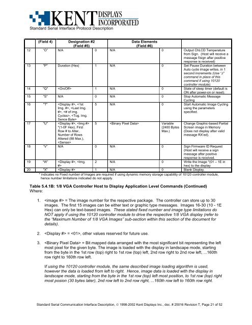
Table 5.4.1B: 1/8 VGA Controller Host to Display Application Level Comm<strong>and</strong>s (Continued)<br />
Where:<br />
1. = The image number for the respective package. The controller can store up to 30<br />
images. The first 15 images can be either text or graphic type messages. Images 16-30 (10 - 1E<br />
Hex) can only be text-based images. These stated fixed number <strong>and</strong> image type limitations do<br />
NOT apply if using the 10120 controller module to drive the respective 1/8 VGA display (refer to<br />
the “Maximum Number of 1/8 VGA Images” sub-section within this section of the document for<br />
details).<br />
2. = , other values reserved for future use.<br />
3. = Bit mapped data arranged with the most significant bit representing the left<br />
most pixel for the given byte. The image is loaded with the display in l<strong>and</strong>scape mode, starting<br />
from the byte in the 1st row (top) right to 1st row (top) left, 2nd row right to 2nd row left, ...160th<br />
row right to 160th row left.<br />
If using the 10120 controller module, the same described image loading algorithm is used,<br />
however the data is loaded from left to right. Hence, image data is loaded with the display in<br />
l<strong>and</strong>scape mode, starting from the byte in the 1st row (top) left most position, to 1st row (top) right<br />
most posion (30 bytes later), 2nd row left to 2nd row right, ...160th row left to 160th row right.<br />
St<strong>and</strong>ard Serial Communication Interface Description, © 1998-2002 Kent Displays Inc., doc. # 25016 Revision T, Page 21 of 52