STANDARD SERIAL COMMUNICATION INTERFACE and ...
STANDARD SERIAL COMMUNICATION INTERFACE and ...
STANDARD SERIAL COMMUNICATION INTERFACE and ...

You also want an ePaper? Increase the reach of your titles
YUMPU automatically turns print PDFs into web optimized ePapers that Google loves.
St<strong>and</strong>ard Serial Interface Protocol Description<br />
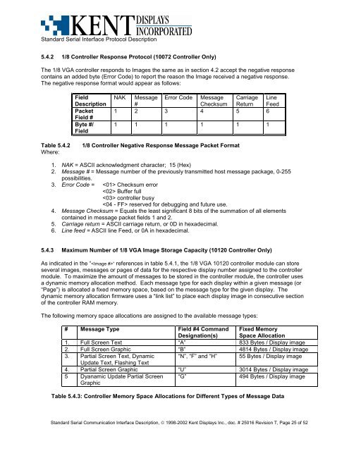
5.4.2 1/8 Controller Response Protocol (10072 Controller Only)<br />
The 1/8 VGA controller responds to Images the same as in section 4.2 accept the negative response<br />
contains an added byte (Error Code) to report the reason the Image received a negative response.<br />
The negative response format would appear as follows:<br />
Field<br />
Description<br />
Packet<br />
Field #<br />
Byte #/<br />
Field<br />
NAK Message<br />
#<br />
Error Code Message<br />
Checksum<br />
Carriage<br />
Return<br />
Line<br />
Feed<br />
1 2 3 4 5 6<br />
1 1 1 1 1 1<br />
Table 5.4.2<br />
Where:<br />
1/8 Controller Negative Response Message Packet Format<br />
1. NAK = ASCII acknowledgment character; 15 (Hex)<br />
2. Message # = Message number of the previously transmitted host message package, 0-255<br />
possibilities.<br />
3. Error Code = Checksum error<br />
Buffer full<br />
controller busy<br />
reserved for debugging <strong>and</strong> future use.<br />
4. Message Checksum = Equals the least significant 8 bits of the summation of all elements<br />
contained in message packet fields 1 <strong>and</strong> 2.<br />
5. Carriage return = ASCII carriage return, or 0D in hexadecimal.<br />
6. Line feed = ASCII line Feed, or 0A in hexadecimal.<br />
5.4.3 Maximum Number of 1/8 VGA Image Storage Capacity (10120 Controller Only)<br />
As indicated in the “” references in table 5.4.1, the 1/8 VGA 10120 controller module can store<br />
several images, messages or pages of data for the respective display number assigned to the controller<br />
module. To maximize the amount of messages to be stored in the controller module, the controller uses<br />
a dynamic memory allocation method. Each message type for each display within a given message (or<br />
“Page”) is allocated a fixed memory space, based on the message type for the given display. The<br />
dynamic memory allocation firmware uses a “link list” to place each display image in consecutive section<br />
of the controller RAM memory.<br />
The following memory space allocations are assigned to the available message types:<br />
# Message Type Field #4 Comm<strong>and</strong><br />
Designation(s)<br />
Fixed Memory<br />
Space Allocation<br />
1. Full Screen Text “A” 833 Bytes / Display image<br />
2. Full Screen Graphic “B” 4814 Bytes / Display image<br />
3. Partial Screen Text, Dynamic “N”, “F” <strong>and</strong> “H” 55 Bytes / Display image<br />
Update Text, Flashing Text<br />
4. Partial Screen Graphic “U” 3014 Bytes / Display image<br />
5 Dyanamic Update Partial Screen<br />
Graphic<br />
“G”<br />
494 Bytes / Display image<br />
Table 5.4.3: Controller Memory Space Allocations for Different Types of Message Data<br />
St<strong>and</strong>ard Serial Communication Interface Description, © 1998-2002 Kent Displays Inc., doc. # 25016 Revision T, Page 25 of 52