installation instructions - KJG
installation instructions - KJG
installation instructions - KJG

Create successful ePaper yourself
Turn your PDF publications into a flip-book with our unique Google optimized e-Paper software.
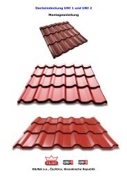
UNI 1 and UNI 2 Metal Roofing<br />
Technical Installation Guide<br />
K&J&G a.s., Čachtice, Slovak Republic
CONTENTS<br />
1. MATERIAL AND SURFACE FINISH<br />
1.1. Coloured surface finishes for zinc coated sheet metal<br />
1.2. Coloured surface finishes for aluminium sheet metal<br />
1.3. Purpose and use<br />
2. TYPE AND INTENDED USE OF UNI 1 AND UNI 2 ROOFING<br />
2.1. UNI 1 roofing<br />
2.2. UNI 2 roofing<br />
2.3. Accessories<br />
2.4. Detailed product description<br />
3. TRANSPORT, STORAGE AND HANDLING<br />
3.1. Transport and storage<br />
3.2. Handling<br />
4. DESIGN PARAMETERS FOR ROOF SUPPORTING STRUCTURES<br />
4.1. Lath parameters<br />
4.2. Lath <strong>installation</strong> under the roofing material<br />
4.2.1. With drip edge flashing<br />
4.2.2. Without drip edge flashing<br />
4.3. Roof underlayment - waterproofing, design and <strong>installation</strong><br />
4.4. Lengths of individual roofing sheets.<br />
4.4.1. Defining proper lengths including overlapping<br />
5. INSTALLATION OF INDIVIDUAL COMPONENTS<br />
5.1. Initial <strong>installation</strong> conditions - roof inspection<br />
5.2. Fascia board and edge flashing - <strong>installation</strong><br />
5.2.1. Full peak end cap above the edge flashing<br />
5.2.2. Peak under the edge flashing<br />
5.3. Roofing material <strong>installation</strong><br />
5.4. Roofing sheet <strong>installation</strong><br />
5.5. Screws for installing UNI 1 roofing and accessories<br />
5.6. Custom cutting roofing materials<br />
5.7. Walking on installed sheets<br />
5.8. Snow barriers - use<br />
5.9. Peak - use and <strong>installation</strong><br />
5.10. Valley flashing<br />
5.11. Penetration bushings<br />
5.12. Roof-mounted windows<br />
5.13. Transposing roof slopes
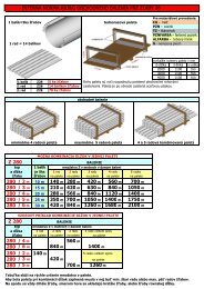
TECHNICAL DATA FOR UNI 1 AND UNI 2 LIGHT ROOFING<br />
1. MATERIAL AND SURFACE FINISH<br />
1.1. Zinc coated sheet metal with Myrialac and Myriamatt-T:<br />
Steel sheet metal hot dipped zinc coated pursuant to the STN EN 10169-1 standard<br />
(Continuously organic coated (coil coated) steel flat products. Section 1: General information<br />
(definitions, materials, tolerances, test methods)), thickness 0.50mm, pursuant to STN EN 10327<br />
(Continuously hot-dip coated strip and sheet of low carbon steels for cold forming. Technical delivery<br />
regulations), quality DX51D +Z200, delivered pursuant to STN EN 10142 (Continuously hot-dip<br />
zinc coated low carbon steels strip and sheet for cold forming. Technical delivery regulations) with<br />
organic polyester surface finish, thickness: SP 25µm, or matte polyester, thickness: SP 35µm on<br />
the face side and thickness: SP 7µm on the back side. The sheet metal is delivered pursuant to STN<br />
EN 10204 (Metallic products. Types of inspection documents).<br />
A detailed description of the raw sheet metal used to produce the roofing material is provided at:<br />
Material sheets for MYRIAD-Myrialac, Myriamatt-T<br />
Basic GLOSS and MATTE colour shades, 0.5 mm thick.<br />
TM-Terra brown OČ-Oxide red MH-Copper brown MŠ-Anthracite grey<br />
RAL 8028 RAL 3009 RAL 8004 RAL 7016<br />
Basic GLOSS colour shades, 0.5 mm thick.<br />
TH-Chocolate brown HČ–Brown red IČ- Jet black BH-Aluminium white B-White ŠB-Grey white<br />
RAL 8017 RAL 3011 RAL 9005 RAL 9006 RAL 9010 RAL 9002<br />
Custom GLOSS colour shades, 0.55 mm thick.<br />
MZ-Moss green PŠ-Dusty grey MOT- Gentian blue MM-Metallic copper<br />
RAL 6005 RAL 7037 RAL 5010 extra RAL
1.2. Surface finish on coloured Novelis aluminium sheet metal:<br />
Aluminium sheet metal, thickness 0.68mm, material EN-AW 3105 pursuant to EN 573/3:2008<br />
(Aluminium and aluminium alloys. Chemical composition and form of wrought products. Section 3:<br />
Chemical composition.), delivered pursuant to STN EN with organic polyester surface finish,<br />
thickness: 20 m on the face side and polyurethane, thickness: 4 m on the back side.<br />
A detailed description of the raw sheet metal used to produce the roofing material is provided at:<br />
Material sheets for NOVELIS<br />
Basic GLOSS and MATTE colour shades, 0.68mm thick.<br />
TM-Terra brown OČ-Oxide red MH-Copper brown MŠ-Anthracite grey<br />
RAL 8028 RAL 3009 RAL 8004 RAL 7016<br />
1.3. Purpose and use<br />
UNI 1 and UNI 2 metal roofing is designed as lightweight roofing material for roofs with a minimum<br />
slope of 14° with lengthwise joints or for roofs with a minimum slope of 12° without lengthwise<br />
joints with lath spacing of 350 mm or 400 mm depending on the type of modules used. Minimum<br />
lengths are 475 mm (for 350 modules) and 525 mm (for 400 modules). The maximum length is<br />
6500 mm (for both 350 and 400 modules). The product can only be used when a structural<br />
assessment of the load bearing structure has been completed for the expected load. Product service<br />
life depends on the environment of <strong>installation</strong> and the surface finish. The stipulated service life can<br />
be achieved when used as designed and when treated with an appropriate surface finish. UNI 1 and<br />
UNI 2 metal roofing is manufactured by cold forming steel or aluminium sheet metal into a wavy<br />
shape with lengthwise ridges.
2. TYPE AND INTENDED USE OF UNI 1 AND UNI 2 ROOFING<br />
2.1. UNI 1 roofing<br />
MODULE 350 400<br />
Total width 1195 mm 1195 mm<br />
Structural - covering width 1105 mm 1105 mm<br />
Ridge height 23 mm 23 mm<br />
Offset height 15 mm, 20 mm 20 mm<br />
Overall height 38 mm, 43 mm 43 mm<br />
Minimum length 475 mm 525 mm<br />
Maximum length * 6500 mm 6500 mm<br />
Lath spacing ** 350 mm 400 mm<br />
Minimum possible slope *** 14° 14°<br />
Weight for zinc-coated sheet metal Around 5 kg/m 2 Around 5 kg/m 2<br />
Weight for aluminium sheet metal Around 2.4 kg/m 2 Around 2.4 kg/m 2<br />
* Roofing sheet lengths can be custom ordered to measure (roofing with extended lengths can be produced<br />
after prior agreement)<br />
** See supporting lath methods<br />
*** Min. slope of 14° for lengthwise joints; if the roof has no lengthwise joints, the minimum slope is 12°
2.2. UNI 2 roofing<br />
MODULE 350 400<br />
Total width 1189 mm 1189 mm<br />
Structural - covering width 1100 mm 1100 mm<br />
Ridge height 24.5mm 24.5mm<br />
Offset height 15mm, 20mm 20mm<br />
Overall height 39.5mm, 44.5mm 44.5mm<br />
Minimum length 480 mm 530 mm<br />
Maximum length * 6500 mm 6500 mm<br />
Lath spacing ** 350 mm 400 mm<br />
Minimum possible slope *** 14° 14°<br />
Weight for zinc-coated sheet metal Around 5 kg/m 2 Around 5 kg/m 2<br />
Weight for aluminium sheet metal Around 2.4 kg/m 2 Around 2.4 kg/m 2<br />
* Roofing sheet lengths can be custom ordered to measure (roofing with extended lengths can be produced<br />
after prior agreement)<br />
** See supporting lath methods<br />
*** Min. slope of 14° for lengthwise joints; if the roof has no lengthwise joints, the minimum slope is 12°
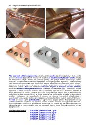
2.3. Accessories.<br />
Accessories for metal roofing sheets (rounded peaks, ventilation peaks, rounded peak end caps, full<br />
profile peak end caps, snow guard sets, corner flashing, simple flashing, valley flashing, etc.) are<br />
produced from the same steel or aluminium sheet metal as the actual roofing material. Accessories<br />
for the roofing system include a complete assortment of accessories that meet the most demanding<br />
quality, colour and functionality requirements to ensure the entire roof system works properly.<br />
Rounded peak, effective width<br />
312mm<br />
Peak vent<br />
Peak end cap - rounded<br />
Self-tapping roofing screws Snow guards 2m (set) Snow retainer<br />
Peak end cap - full Diffusion foil 110g, 130g, 140g UNI roof hatches<br />
UNI 50x60 a 60x60<br />
Drip edge seal - lower Peak seal - upper Universal sealing strip 60mm
MF penetration bushings Ventilation grate 1000/50 Framing protective strip<br />
100x5000mm<br />
Edge flashing - upper Valley flashing Leeward flashing<br />
Edge flashing - lower Edge flashing - flat roof Drip edge flashing<br />
Colour correction spray Magnetic bit 8mm Peak lath holder<br />
Lightning rod system<br />
accessories<br />
Lightning rod system<br />
Stainless peak wire<br />
Lightning rod system<br />
Stainless wire support<br />
Lightning rod system<br />
Stainless wire clip<br />
Lightning rod system<br />
Stainless wire support for standing<br />
seam roof<br />
Lightning rod system, Stainless<br />
wire support for brick
Lightning rod system<br />
Conductor strip, 30x4,<br />
Lightning rod system<br />
AlMgSi wire f8mm 25kg<br />
(1kg/7.1m)<br />
Electric shears<br />
2.4. Detailed Product Description<br />
UNI 1 and UNI 2 roofing sheets with accessories - Shapes and Dimensions<br />
Marking<br />
of product<br />
Profile shape<br />
UNI 1 Metal Roofing<br />
Thickness Coverag<br />
e<br />
width<br />
Part<br />
lengt<br />
h<br />
Weight<br />
of the<br />
material<br />
mm mm mm kg/m 2<br />
UNI 1<br />
23-1105<br />
15-350<br />
15 offset<br />
height<br />
zinc<br />
0.5<br />
aluminiu<br />
m<br />
0.68<br />
1105 min.<br />
475<br />
max.<br />
6500<br />
zinc<br />
4.6<br />
aluminiu<br />
m<br />
2.19<br />
UNI 1<br />
23-1105<br />
20-350<br />
20 offset<br />
height<br />
zinc<br />
0.5<br />
aluminiu<br />
m<br />
0.68<br />
1105 475<br />
to<br />
6500<br />
zinc<br />
4.61<br />
aluminiu<br />
m<br />
2.2<br />
UNI 1<br />
23-1105<br />
20-400<br />
zinc<br />
0.5<br />
aluminiu<br />
m<br />
0.68<br />
1105 525<br />
to<br />
6500<br />
zinc<br />
4.61<br />
aluminiu<br />
m<br />
2.2
UNI 2<br />
24.5-1100<br />
15-350<br />
20-350<br />
20-400<br />
zinc<br />
0.5<br />
0.55<br />
aluminiu<br />
m<br />
0.68<br />
1100 min.<br />
480<br />
max.<br />
6500<br />
zinc<br />
4.9<br />
5.4<br />
aluminiu<br />
m<br />
2.19<br />
UNI 2<br />
24.5-1100<br />
15-350<br />
20-350<br />
zinc<br />
0.5<br />
0.55<br />
aluminiu<br />
m<br />
0.68<br />
1100 480<br />
to<br />
6500<br />
zinc<br />
4.9<br />
5.4<br />
UNI 2<br />
24.5-1100<br />
20-400<br />
Accessories for metal roofing<br />
Marking<br />
of product<br />
Profile shape<br />
Rounded<br />
peak<br />
Peak<br />
end cap -<br />
full<br />
Effective width 312 mm<br />
zinc<br />
0.5<br />
0.55<br />
aluminiu<br />
m<br />
0.68<br />
1100 530<br />
to<br />
6500<br />
zinc<br />
4.9<br />
5.4<br />
Thickness Coverag<br />
e<br />
width<br />
Part<br />
lengt<br />
h<br />
Weight<br />
of the<br />
material<br />
mm mm mm kg/m<br />
zinc<br />
0.5<br />
aluminiu<br />
m<br />
0.68<br />
zinc<br />
0.5<br />
aluminiu<br />
m<br />
0.68<br />
1920<br />
2820<br />
4020<br />
1920<br />
2820<br />
4020<br />
zinc<br />
2.35<br />
3.45<br />
4.92<br />
aluminiu<br />
m<br />
1.12<br />
1.64<br />
2.34
Peak<br />
end cap -<br />
rounded<br />
zinc<br />
0.5<br />
aluminiu<br />
m<br />
0.68<br />
Peak<br />
vent<br />
zinc<br />
0.5<br />
aluminiu<br />
m<br />
0.68<br />
Snow<br />
guard<br />
set:<br />
strip<br />
reinforceme<br />
nt<br />
underlay<br />
screws<br />
zinc<br />
reinforceme<br />
nt<br />
1.5<br />
strip<br />
0.5<br />
underlay<br />
3<br />
screws<br />
4.8x60<br />
4.8x35
Snow<br />
retainer<br />
Zinc<br />
0.55<br />
3. TRANSPORT, STORAGE AND HANDLING<br />
3.1. Transport and storage<br />
Roofing sheets and accessories are transported using enclosed vehicles and trailers. Every package<br />
is marked in a visible location with <strong>instructions</strong> for transport, storage and handling. UNI 1 sheets are<br />
delivered on disposable wooden pallets constructed to provide maximum possible protection for the<br />
roofing material. The roofing material is placed on the pallet so the longest parts are on the bottom<br />
and the shortest are on top. Their exact length and use can be identified from the storage plan,<br />
which is included with delivery. The entire pallet and all roofing material are wrapped with a<br />
protective foil for safety reasons and to protect the materials from damage during transport. Upon<br />
request, we can also deliver roofing materials to the customer with protective foil applied to each<br />
piece individually. Pallet unloading at the customer's site will use a boom arm attached directly to<br />
the transporting vehicle. Flexible rigging equipment must be used during the unloading process. If<br />
the pallet will be stored for an extended period of time, the proper storage conditions must be<br />
followed. Store the pallet in a dry and ventilated area that does not experience large temperature or<br />
fluctuation variances. The ideal storage site for the product is in a dry and ventilated space under<br />
cover that is not exposed to sunlight or under a waterproof tarpaulin and frame structure. This<br />
sheltered structure must be large enough to allow for air to flow between the tarpaulin and the<br />
packaged product. Do not store the roofing material near aggressive chemicals or materials. If the<br />
protective foil is damaged, repair the affected area using new foil in order to prevent moisture and<br />
contaminants from entering into the space (moisture condensing in the packaging may cause<br />
staining). Pallets must be stored flat. Outdoor storage is capped at 1 month (if the protective foil is<br />
not exposed to direct sunlight and the roofing material must be protected against rain). Indoor<br />
storage is capped at 2 months and laths must be installed between the individual pieces in order to<br />
prevent permanent deformation and to ensure sufficient air circulation (we recommend avoiding<br />
long-term storage thanks to our short delivery times). The roofing material can be stored in a<br />
slanted position in order to better drain any condensate that may form. The individual conditions are<br />
shown in the figures.
3.2. Handling<br />
Only carry the roofing material in a flat position and hold the material at the site of lengthwise<br />
ridges, where the material is reinforced. When moving the roofing material up onto the roof<br />
structure, we recommend moving the material using panels on which the individual pieces of the<br />
roof can be pulled. Avoid any lengthwise bending and creasing of the roofing material at all times<br />
during any handling work. Such deformations cannot be removed and cause the <strong>installation</strong> to take<br />
on an unappealing look. Do not pull individual pieces of material on top of one another (may cause<br />
scratching); always lift each piece individually)(see the figure and description)<br />
Lift larger pieces from the ground up to the roof work<br />
surface as follows: A minimum of two panels can be<br />
supported against the roof structure. The ideal panel slope<br />
angle is the same as the roof surface slope angle. A surface<br />
protection layer (i.e. foil or fabric) can be applied at the<br />
contact surface between panels and the roofing material to<br />
lower the risk of damage to the lower side of the roofing<br />
material. The panels can also be replaced by using a<br />
ladder. Once such an angled plane has been created, you<br />
can safely pull the roofing material onto the roof surface.<br />
Do not stand beneath roofing materials when they are<br />
being lifted!<br />
Never pull roofing material along other roofing material when removing<br />
individual sheets from the pallet. Always remove products from their<br />
packaging by lifting and not sliding them in order to prevent damage to the<br />
protective coating. Any sharp edges created after trimming the edges of the<br />
roofing material can cause damage to the painted surface. At least two<br />
workers are required to remove small (under 2 m) roofing materials from<br />
pallets. At least four workers are required when removing larger pieces.<br />
Proper grip and roofing material handling are explained in the figure. The<br />
proper place to grip the material during handling is at a lengthwise or<br />
vertical ridge where the material is reinforced and will not fold and cause<br />
permanent deformation.
Removing the protective foil<br />
Handling larger pieces (at least 4 workers) Handling smaller pieces (up to 2m)<br />
4. DESIGN PARAMETERS FOR ROOF SUPPORTING STRUCTURES<br />
4.1. Lath parameters<br />
The use of UNI 1 roofing materials does not require full cladding for the roof surface. The roof<br />
structure can be designed in a number of ways. UNI 1 roofing materials have a relatively low weight,<br />
around 5 kg/m 2 , which means that its weight is relatively inconsequential with respect to roof<br />
loading. The following are decisive when designing the structure and sizing lath cross-sections:<br />
A. The snow area in which the project is located, STN EN 1991-1-3 (previously STN 73 0035)<br />
B. Roof slope<br />
C. Axial spacing of the roof rafters<br />
Table showing the standard snow loads in individual areas pursuant to the STN EN 1991-1-3 standard.
Snow Zone<br />
Snow<br />
density<br />
I II III IV V<br />
s k – characteristic<br />
property of snow on the<br />
ground (kN/m 2 )<br />
Reference calculation to<br />
snow weight (kg/m 2 )*<br />
0.75 1.05 1.5 2.25 >2.5<br />
75 105 150 225 >250<br />
Fresh 100 kg/m 3 75 cm 105 cm 150 cm 225 cm >250 cm<br />
Reference<br />
calculation Settled (a few hours to days<br />
200 kg/m 3 37.5 cm 53 cm 75 cm 112.5 cm 125 cm<br />
after snow fall)<br />
to snow<br />
layer<br />
Old (a few weeks to months<br />
300 kg/m 3 25 cm 35 cm 50 cm 75 cm 83 cm<br />
after snow fall)<br />
(cm)*<br />
Wet 400 kg/m 3 19 cm 26 cm 37.5 cm 56 cm 62.5 cm<br />
* Reference calculation for characteristic value of snow S k<br />
The following conditions can be used to simplify the design process:<br />
a. Snow load: Group A: I. II. and III. snow zones<br />
Group B: IV. and V. snow zones (mountain and foothill areas)<br />
b. The axial spacing of rafters in family houses is from 900 mm to 1100 mm<br />
c. The inherent weight of the roofing material has no impact on the structural design (around<br />
5kg/m 2 )<br />
These details all lead to simplified rules for determining lath dimensions:<br />
a. Roofing laths 50x40mm for the snow zones in Group A and for roof slopes over 20° and rafter<br />
spacing of up to 900mm<br />
b. Roofing laths 60x40mm for the snow zones in Group B and for roof slopes under 20° and rafter<br />
spacing of up to 1100mm<br />
These simplified rules do not replace a professional calculation and sizing of the roof structure and<br />
its individual components by a certified designer. The actual design process is complex and affected<br />
by a number of factors, which is the reason why this operation should be left to a design<br />
professional for this area. The simplified version is simply provided to give a representative<br />
example.<br />
Map of snow load characteristics on the ground s k for snow zones I to V in Slovakia (source: STN EN<br />
1991-1-3/NA).<br />
4.2. Lath <strong>installation</strong> under the roofing material
4.2.1. Lath spacing when using drip edge flashing. 4.2.2. Lath spacing without using drip edge flashing.<br />
All roofing laths are secured in the same manner. The top of the first roofing lath must be perpendicular to the top<br />
plate lath installed on the rafter.<br />
4.2.1. With drip edge flashing<br />
Spacing of 350 mm for roof laths is the same as for all<br />
other roof laths when using 350 roofing modules; the<br />
roofing material is not inserted into the gutter. The final<br />
roof lath near the peak is around 50 mm from the peak<br />
itself. Before securing the roofing material, the drip<br />
edge flashing is first installed on the first roof lath; this<br />
flashing is inserted at least 1/3 of the width of the<br />
gutter. The roofing material is then secured to the roof<br />
lath using roofing screws in the lower part of the ridge<br />
under the offset. A lower drip edge seal should be<br />
installed between the drip edge flashing and the roofing<br />
material.<br />
(Roof lath spacing is 400 mm for 400 roofing modules)<br />
4.2.2. Without drip edge flashing<br />
Spacing of 350 mm for roof laths is the same for all<br />
other roof laths when using 350 roofing modules except<br />
for the first gap, which is 280 mm and the roofing<br />
material is inserted at least 1/3 of the width of the<br />
gutter. The first gap must be adjusted if the roofing<br />
material will be inserted into the gutter in any other<br />
manner. The first roof lath is secured with the top side<br />
perpendicular to the top plate lath installed on the rafter<br />
(15 or 20 mm higher depending on sheet thickness).<br />
The final roof lath near the peak is around 50 mm from<br />
the peak itself. The roofing material is secured to the<br />
roof lath using roofing screws in the lower part of the<br />
ridge under the offset into the first lath in the lower<br />
section of the ridge.<br />
(Roof lath spacing is 400 mm for 400 roofing modules<br />
with the gap for the first roof lath set to 320 mm)<br />
4.3. Roof underlayment - waterproofing, design and <strong>installation</strong><br />
The proper selection, use and <strong>installation</strong> of roof underlayment is critical to ensure 100%<br />
functionality of a roof. A high efficiency diffusion barrier is used with insulated roofing material. Roof<br />
underlayment is applied directly onto the roof structure. Begin parallel to the drip edge and then<br />
move from the drip edge to the tops of the rafters. Underlayment overlap near the drip edge and<br />
the peak must be at least 200 mm past the level of the wall. Temporarily fix the underlayment using
staples to the rafters. Permanently secure the underlayment by nailing it to the top plate lath (the<br />
gap ensures that the roof is ventilated) from the upper edge of the underlayment in the direction of<br />
the rafters. Leave the underlayment slightly loose between the rafters (with a maximum of 40 mm<br />
of play in the middle of the gap between rafters). Complete underlayment <strong>installation</strong> at the roof<br />
peak following the <strong>installation</strong> guide provided for individual specific details. At horizontal joints the<br />
underlayment must overlap by around 150 mm. If the underlayment needs to be adjusted in a<br />
lengthwise direction, do so at a rafter and ensure that the overlap is at least 100 mm. Tape the<br />
underlayment together using double-sided tape recommended by the underlayment producer for<br />
roofs with slopes under 14°.<br />
The roofing material cannot come into direct contact with wet or fresh cut lumber, wet concrete or<br />
with copper or water leaking from copper materials on the roofing material itself. The roofing<br />
material should not be exposed to vapours that cause corrosion, ash or cement dust. Organic debris<br />
(leaves and branches, etc.) must be removed from the surface. When connecting roofing with<br />
different surface finishes, first consider the possibility of contact corrosion between the roofing<br />
materials. The method and conditions of use must be consulted with the manufacturer in the event<br />
the roofing material will be used for any purpose other than its intended purpose.<br />
4.4. Lengths of individual roofing sheets.<br />
The coefficient of thermal expansion for zinc coated sheet metal is 3.97mm/m/100°C. During the<br />
summer months the metal may approach temperatures of around 80°C. The maximum length of a<br />
single piece of roofing material due to such thermal expansion is recommended to be 6500 mm or<br />
less. Given ease of handling concerns, we recommend using lengths of individual pieces of no more<br />
than 4000 mm. A common situation is where two sheets have to be connected to one another. The<br />
overlap between the two pieces must be at least 140 mm (for both 350 and 400 roof modules). The<br />
length of such overlap must be calculated when measuring and ordering roofing materials and<br />
determining the proper length.<br />
4.4.1. Defining proper lengths including overlapping<br />
If the total length A (from the top centre of the peak to<br />
the drip edge) is larger than 6500 mm then two roofing<br />
sheets must be used. The overlap, defined as D, is at least<br />
140 mm. Follow the <strong>instructions</strong> below to define the<br />
length C of the upper piece: Divide the total length A in<br />
half. Use the actual, real dimension from the critical<br />
length table for such an approximation of the length B of<br />
the lower piece. Here it is important to also consider the<br />
given roofing module (350 or 400). Now you have a<br />
defined value for length B of the lower part. From the<br />
total length A, subtract the length B of the lower piece but<br />
don't forget to add the overlap D. The result is the length<br />
C of the upper piece, which should be checked against the<br />
critical length table. To check: B+C-D=A (which is the<br />
total length)
5. INSTALLATION OF INDIVIDUAL COMPONENTS<br />
5.1. Initial <strong>installation</strong> conditions - roof inspection<br />
UNI 1 roofing material can be used on roofs<br />
with a slope of at least 14°. This condition<br />
must be respected, otherwise our warranty is<br />
null and void. Be sure to measure and check<br />
all dimensions of the roof framing structure<br />
before beginning the <strong>installation</strong> of the<br />
roofing material. Roof corners and edges (the<br />
drip edge to side and peak to side) must all<br />
be right angles (90°) and the drip edge must<br />
be parallel to the peak. All measurements<br />
must be checked at multiple places. We can<br />
check for squareness using simple measurements of the diagonals from the corners. The following<br />
conditions must apply: distance A = distance B (see the figure above). Small deviations of up to 2<br />
cm can be resolved by adjusting the laths and flashing before the roofing material is installed.<br />
Larger dimensional issues must be resolved as they may cause irregularities in the edges of the roof<br />
and may lead to a shift in the ridge pattern in the roofing material during <strong>installation</strong>. The flatness of<br />
the roof laths is also important to ensure that the fasteners do not create a wavy pattern on the<br />
roofing surface, symptoms of which primarily include a lack of reliability in overlapping joints.<br />
5.2. Fascia board and edge flashing - <strong>installation</strong><br />
The edge of the fascia board must be installed in a position above the laths before the roofing<br />
material is installed; the gap must equal the height of the roofing material itself. The fascia board<br />
extends over the laths by around 45 mm for UNI 1 (the exact height of the roofing material itself).<br />
Edge flashing is installed from the drip edge up to the peak. The final piece of the edge flashing<br />
must be cut to the proper length at the peak. Edge flashing overlap is at least 100 mm. Edge<br />
flashing must overlap the first vertical ridge in the roofing sheet. Edge flashing is composed of two<br />
sections. Secure the lower part of the edge flashing, the lower flashing, to the fascia board before<br />
installing the roofing material on the laths. Secure the flashing to the fascia board and then to the<br />
laths (using nails and clips). Once the roofing material has been installed, properly position the<br />
upper part of the edge flashing. Secure this part with 4.8 x 35 screws to the fascia board (400 mm<br />
spacing) and 4.8 x 20 screws to the vertical ridge of the sheet (around 1 m spacing). One of the<br />
following methods is used for terminating the edge flashing at the peak.
5.2.1. Full peak end cap above the edge flashing<br />
Once the roofing material has been installed, properly position the upper part of the edge flashing.<br />
Secure this part with 4.8 x 35 screws to the fascia board (400 mm spacing) and 4.8 x 20 screws to<br />
the vertical ridge in the roofing material (around 1 m spacing). Secure the full peak end cap with 4.8<br />
x 20 screws to the peak and then secure it and the peak itself to the upper section of the roofing<br />
material with 4.8 x 20 screws with spacing of around 300 mm.<br />
5.2.2. Peak under the edge flashing<br />
After the roofing material has been installed, secure the peak using 4.8 x 20 screws to the upper<br />
section of the profile on the roofing material with spacing of around 300 mm. This case does not<br />
require the use of a full peak end cap. The upper section of the edge flashing is then secured to the<br />
fascia board. Secure this part with 4.8 x 35 screws to the fascia board (400 mm spacing) and 4.8 x<br />
20 screws to the vertical ridge in the roofing material (around 1 m spacing).<br />
5.3. Roofing material <strong>installation</strong><br />
Roofing material <strong>installation</strong> uses a laying plan, which is always included in delivery. All roofing<br />
accessories must first be installed before the roofing material itself, i.e. drip edges, drip edge ends,<br />
valley flashing and fascia boards. The roofing layer can be laid using two basic methods:<br />
A. Roofing <strong>installation</strong> from left to right B. Roofing <strong>installation</strong> from right to left<br />
When laying roofing sheets from left to right, we always lay the next sheet beneath the raised edge<br />
of the previous sheet of roofing material. The underlay roofing material is tightly secured in this<br />
manner without fasteners by the upper sheet, which simplifies and makes the resulting joints more<br />
reliable. This <strong>installation</strong> method is suited to roofs with steeper slopes and when using longer length
oofing materials. The sheet is placed on the previous sheet with laying the roofing materials from<br />
right to left. The decision regarding one or the other method depends on a number of factors<br />
including the shape of the roof surface (windows, dormers, sharp angle cuts, chimneys, etc.), the<br />
type of roof, prevailing wind direction, roof slope and the length of the individual roofing materials.<br />
The <strong>installation</strong> method should be chosen by a professional who will then complete the <strong>installation</strong><br />
itself. In both cases it is critical to follow a simple rule: the drainage groove (on the left-hand side of<br />
the roofing material) on the lower sheet must always be covered by the top sheet and cannot be<br />
broken or disturbed at any spot with a fastener screw (loss of groove integrity).<br />
5.4. Roofing sheet <strong>installation</strong><br />
Once a decision has been made on the <strong>installation</strong><br />
method (from left to right or vice versa), place the<br />
first sheet on the side where you will start. The<br />
sheet must be properly positioned over the drip<br />
edge (at least 40 mm) so that it extends over 1/3<br />
the width of the gutter. Level out the roofing sheet<br />
with the drip edge on the roof and install one 4.8 x<br />
35 screw near the drip edge into the lath on the<br />
roofing frame and temporarily near the upper edge<br />
of the sheet towards the peak (Fig. 1). Position the<br />
second sheet on the first sheet so that the drainage<br />
groove is covered and that the profiles line up at the<br />
edges of the sheets in a break along the horizontal<br />
ridges in the sheets. The lower drip edge of the<br />
sheets must create a straight line. Then use 4.8 x<br />
20 self-drilling screws to secure both sheets along<br />
the entire overlap below the offset in the upper<br />
section of the sheet (Fig. 2). Use the same method<br />
to connect three to four sheets while securing each<br />
of the individual sheets to the lath with a single<br />
screw in the upper corner towards the peak. Ensure<br />
the drip edge along the entire lower portion of the<br />
roof is straight. Leave the sheet secured with a<br />
single screw in one of the corners and then move up<br />
and down (Fig. 3) until the desired alignment of the<br />
lower section of the joined sheets with the drip edge<br />
of the roof is achieved. If needed, the initial screw<br />
can be removed from the lath and reinstalled at<br />
another location in order to make this alignment<br />
perfect. Once the proper position has been<br />
achieved, use an appropriate quantity of 4.8 x 35<br />
screws to secure the individual sheets to the lath<br />
structure (Fig. 4). Now the drip edge is straight and<br />
you can install additional sheets. Every installed<br />
sheet must be secured to the previous sheet at the<br />
overlap using 4.8 x 20 mm screws in the upper<br />
ridge below each lengthwise offset and then to the<br />
lath structure using 4.8 x 35 mm screws in the<br />
lower flat section of the sheet. It is critical that<br />
every sheet be properly positioned during the laying<br />
process and be free of any deformations or<br />
curvature. Every sheet must be installed<br />
perpendicular to the drip edge.<br />
Anchoring screws on the roofing material must be<br />
spaced as shown in the figures. 4.8 x 35 screws are<br />
used in every ridge of the sheet on the lower and<br />
upper sides and the edges of the panels; the screws<br />
are installed to the laths in the lower flat section.<br />
In even rows, starting with the second from the<br />
bottom, 4.8 x 35 screws are installed in every<br />
second ridge of the sheet; the screws are installed<br />
to the laths in the lower flat section.
4.8 x 20 screws connect the sheets at overlapping sheets along the vertical ridge about 1 cm below<br />
every lengthwise offset in the side section of the sheet.<br />
Total screw consumption is around 8 per m 2 . The peak is secured using 4.8x20 screws installed into<br />
every second peak of the ridge structure.<br />
4.8 x 35 screws are used to anchor the sheets to the lath structure at around 1 cm below the<br />
lengthwise offset in the lower section of the sheet.<br />
The overlapping sheet joints are secured using self-drilling 4.8 x 30 screws installed around 1 cm<br />
below every lengthwise offset in the side section of the sheet. Attention! Screws cannot interrupt or<br />
interfere with the drainage groove!<br />
5.5. Screws for installing UNI 1 and accessories<br />
Self-drilling screws made from high quality steel are<br />
used to install UNI 1 roofing materials. The screws are<br />
delivered with the same surface finish as the roofing<br />
material. The screws include washers, which also feature<br />
an EPDM gasket material on the bottom. EPDM -<br />
(ethylene propylene diene M-class) is a synthetic polymer<br />
with exceptional physical and mechanical properties<br />
including resistance to atmospheric conditions and a<br />
number of chemicals. The washer and gasket ensure<br />
that the connection is 100% waterproof. We use 3 types<br />
of screws during <strong>installation</strong>:<br />
1. 4.8 x 20 screws are used to connect roofing sheets and accessories (metal on metal joints). The<br />
screw is positioned in the upper ridge beneath the offset in the sheet overlap (also used to secure<br />
the end cap and side flashing to the metal roofing).<br />
2. 4.8 x 35 screws are used to anchor the metal sheets to the lath structure (wood to metal<br />
joints). The screw is anchored in the lower flat section of the sheet's ridge as close to the lengthwise<br />
offset as possible.<br />
3. 4.8 x 60 screws are used to secure the snow barriers to the roof structure (wood to metal<br />
joints). These screws are installed in the lower cleats of the snow barriers and are secured to laths.<br />
The full functionality and the service life of both joints and screws can only be achieved by using the<br />
recommended <strong>installation</strong> tools. An electric driver with adjustable torque should be used to install<br />
the screws. The required quantity and type of screws is defined on the basis of documentation<br />
completed for each project individually. Reference fastener<br />
consumption is around 8 per m 2 .<br />
Proper torque adjustment for anchoring screws<br />
A - Properly set torque (even base, compressed gasket - slightly<br />
rounded around the circumference)
B - Excessive torque (EPDM gasket is deformed, may crack and lose the ability to make a seal)<br />
C – Low torque (washer with EPDM gasket has insufficient sealing ability)<br />
A B C<br />
5.6. Custom cutting roofing materials<br />
If angled edges need to be corrected or if the straight<br />
edges of the roofing material are too long, please<br />
follow these <strong>instructions</strong>: If possible, cut all edges on<br />
the ground or on a hard surface. Manual tin snips or<br />
electric shears are used to cut the sheet metal. An<br />
angle grinder with a cut off wheel can never be used<br />
to cut the metal sheets. The resulting edge has been<br />
exposed to heat, which destroys the protective coating<br />
and significantly reduces service life. The shards and<br />
tearing cause corrosion to appear more quickly. The<br />
use of an angle grinder immediately voids any<br />
warranty. The use of an angle grinder with a cut off<br />
wheel is forbidden! If a sheet must be cut on the roof,<br />
remove any shavings or shards that are created when<br />
making the cut (subsequent oxidation may cause<br />
corrosion and colour changes and decrease the service<br />
life of the roof or cause fastener problems if they get<br />
into joints). Use the correction pen to touch up the<br />
paint that has been damaged at the cutting sites.<br />
Clean the damaged surfaces using a petroleum-based<br />
solvent and then treat with the appropriate shade of<br />
paint (correction pen or paint). Do not use any<br />
nitrogen or chlorinated rubber solvents! During<br />
<strong>installation</strong>, it's critical to treat all cut edges, including those edges that were cut during the roofing<br />
material production process.<br />
5.7. Walking on installed sheets<br />
Installation is conducted so that no one walks over the roofing materials. If this is not possible, the<br />
roofing materials can be walked on with soft-soled shoes but you must walk on the lower section of<br />
the ridge where laths are installed (there is no risk of deforming the sheet in these spots). Before<br />
walking on the metal roofing, check to ensure your shoe soles are clean (that there is no metal, dirt,
wood, sand or other abrasives that may damage the sheet surfaces). If needed to distribute the<br />
load, additional supports can be used (allows for the distribution of the load over a larger area,<br />
thereby decreasing the real area on which the load is applied).<br />
5.8. Snow protection - application<br />
Snow retainers are installed:<br />
- Where snow falling from the roof can pose a hazard to pedestrians or damage other structures.<br />
- Where snow collects due to movement on the roof (e.g. in valleys)<br />
- Where moving snow could damage the roof structure or roofing sheets.<br />
- Snow retainers are used to hold snow on the roof, which acts as additional insulation.<br />
We deliver two forms of snow protection: K&J&G snow retainers for UNI 1 and UNI 2 roofing<br />
(designed for use in areas with low and moderate snow loads, see snow zones I, II and III in the<br />
map of snow zones in Slovakia) and snow guards (for snow zones IV and V). The required number<br />
of snow retainers depends on the slope of the roof and the quantity of precipitation in the given<br />
area.<br />
Snow retainer<br />
retainers in a number of consecutive rows.<br />
Snow barrier<br />
Pursuant to STN 1991-2-3:<br />
The forces acting on a retainer are defined as follows:<br />
F s = s x b x sinα s = µ i x s k<br />
Legend:<br />
F s - Snow load on the retainer in the direction of shear<br />
(kN/m)<br />
s – Snow load on the roof (kN/m 2 )<br />
b – Distance from barrier to the peak or from the<br />
previous row of snow retainers (m)<br />
α - Roof slope (°)<br />
µ i - Shape coefficient (0.8 - 1.6)<br />
s k - Snow load based on snow zone (kN/m 2 )<br />
The calculation is defined for static loading. The<br />
dynamic force induced by the movement of the snow<br />
is not considered in this calculation and is much<br />
higher than the static load. In order to define this<br />
component, it would be appropriate to install the snow<br />
The placement and use of snow retainers can also be determined based on experience in the given<br />
site of <strong>installation</strong>. If <strong>installation</strong> is taking place in an area where no such information exists, they<br />
can be installed by observing similar <strong>installation</strong>s on buildings in the area that appear functional. A<br />
designer can also calculate these loads if all the roof details are included in the project.<br />
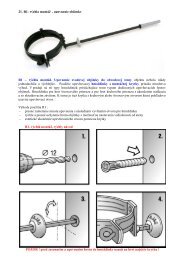
5.8.1. Installation of snow retainers<br />
The <strong>installation</strong> of K&J&G snow retainers is clear from the<br />
figure. One retainer is comprised of the retainer body itself<br />
in the same colour as the roof and 3x25x80 anchoring<br />
screws and EPDM washers. A snow retainer is anchored to<br />
the roofing panels using two 4.8 x 60 screws and into the<br />
roofing sheet using two 4.8 x 35 screws. An EPDM gasket is<br />
inserted between the lower part of the snow retainer and<br />
the roofing material to ensure the joint is sealed. The<br />
quantity of snow retainers and their <strong>installation</strong> locations on
the roof itself are defined on the basis of a calculation (depending on the type of roof and the snow<br />
zone). The procedure is shown below. This type of protection is suitable for snow zones I., II. and<br />
III. (see the table with snow zones in the Slovak Republic). Such protection is inadequate for zones<br />
IV. and V.<br />
Fig. 1<br />
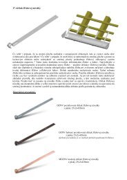
Snow barrier <strong>installation</strong> is clear from the figure. The<br />
barrier comprises the actual barrier component, which is 2<br />
m long and in the same colour as the roofing, an "L"<br />
reinforcement bracket that is 2 m long, anchoring screws<br />
and EPDM washers. A snow barrier is anchored to the<br />
roofing panels using two 4.8 x 60 screws and into the<br />
roofing sheet using two 4.8 x 35 screws. An EPDM gasket is<br />
inserted between the reinforcing bracket and the roofing<br />
material to ensure the joint is sealed. The quantity of snow<br />
barriers and their <strong>installation</strong> locations on the roof itself are<br />
defined on the basis of a calculation (depending on the type<br />
of roof and the snow zone). The procedure is shown below.<br />
This type of protection is primarily recommended for snow<br />
zones IV. and V. (see the table with snow zones in the<br />
Slovak Republic). It can also be used for snow zones I., II. and III.<br />
Fig. 2<br />
We recommend using snow barriers in areas with large<br />
snowfall totals (see the map of snow zones). Construction<br />
standards also require the use of snow barriers and they<br />
can be used to protect gutter systems from deformation<br />
when snow moves and to protect people. Snow barriers<br />
should be positioned on the roof surface in critical areas<br />
where the movement of snow could cause damage to roof<br />
components or pose a risk of falling snow for people and<br />
items below the roof (roof-mounted windows, entrances to<br />
the building, parking lots, walkways, etc.). A snow barrier<br />
can be installed in a single row or in multiple overlapping<br />
rows. The use and design of snow barriers must be<br />
consulted with professionals at our sales outlets. Snow<br />
barrier <strong>installation</strong> is clear from the figures. A barrier is comprised of the snow barrier itself in the<br />
same colour as the roof, reinforcement, anchoring screws and EPDM washers. A snow barrier is<br />
anchored to the roofing panels using 4.8 x 60 screws and into the roofing sheet using 4.8 x 35<br />
screws. An EPDM gasket is inserted between the lower part of the snow barrier (reinforcement) and<br />
the roofing material to ensure the joint is sealed.<br />
5.8.2. Defining the type of snow protection, placement and minimum quantity on the roof<br />
surface:<br />
A B C D E<br />
5.8.2.1. Angled roof, slope from 14° to 45° with rafter length of up to 5m.<br />
For snow zones I. and II. (see the snow zone map of Slovakia), the <strong>installation</strong> method is even in<br />
two consecutive rows (the first two rows from the drip edge) alternating over every fourth lower<br />
ridge in the sheet for each row with a two ridge offset between the rows (see Fig. A and Fig.1).
For snow zone III. (see the snow zone map of Slovakia), the <strong>installation</strong> methods is the same with<br />
an increased number of retainers per standard meter in two consecutive rows (the first two rows<br />
from the drip edge) alternating over every second lower ridge. (see Fig. B and Fig. 1).<br />
For roofs in snow zones IV. and V. (see the snow zone map of Slovakia), other protection using<br />
snow barriers is recommended. Here the coverage width is 2 m and anchored to every upper ridge<br />
on the sheet (from the upper edge of the snow barrier to the roofing lath using a reinforcing<br />
bracket) in the area above the first lengthwise offset above the drip edge. (see Fig. E and Fig. 2).<br />
5.8.2.2. Angled roof, slope from 14° to 45° with rafter length of up to 7m.<br />
For snow zones I. and II. (see the snow zone map of Slovakia), the <strong>installation</strong> method is even in<br />
two consecutive rows (the first two rows from the drip edge) alternating over every fourth lower<br />
ridge and two more rows (in the middle of the rafter's span) alternating over every fourth lower<br />
ridge. There are a total of 4 rows with twice the number of retainers (see Fig. C and Fig. 1).<br />
For snow zone III. (see the snow zone map of Slovakia), the <strong>installation</strong> method is even in two<br />
consecutive rows (the first two rows from the drip edge) with more retainers per standard metre<br />
alternating over every second lower ridge and two more rows (in the middle of the rafter's span)<br />
alternating over every fourth lower ridge. There are a total of 4 rows with twice the number of<br />
retainers (see Fig. D and Fig. 1).<br />
For roofs in snow zones IV. and V. (see the snow zone map of Slovakia), other protection using<br />
snow barriers is recommended. Here the coverage width is 2 m and anchored to every ridge peak on<br />
the sheet (from the upper edge of the snow barrier to the roofing lath using a reinforcing bracket) in<br />
the area above the first lengthwise offset above the drip edge. (see Fig. E and Fig. 2).<br />
Warning!<br />
Snow zones IV. and V. (see the snow zone map of Slovakia) are considered to be the extreme zones. In such case the design<br />
of snow barriers and retainers is subject to an individual assessment based on the customer's request. The type, quantity<br />
and placement of snow retainers are defined by the Technical Department at K&J&G on the basis of a specific order.<br />
5.8.3. Defining the number of snow retainers<br />
The length of the edge near the drip edge (in metres) is multiplied by the given coefficient (number<br />
per standard metre) for the given type of roofing material and the snow zone.<br />
Rafter length Up to 5m Up to 7m<br />
Snow Zone I II III IV V I II III IV V<br />
Units per roofing 2.5 2.5 5 guard guard 5 5 10 guard guard<br />
strip<br />
Units per BM for 2.21 2.21 4.42 guard guard 4.42 4.42 8.84 guard guard<br />
UNI 1<br />
Units per BM for<br />
UNI 2<br />
2.31 2.31 4.62 guard guard 4.62 4.62 9.24 guard guard<br />
Example quantity calculation<br />
The length of the roof near the drip edge is 6 m and the rafters are 5 m long. UNI 1 roofing material<br />
is installed and the project is located in snow zone II.<br />
6 x 2.21 = 13.26 (length of the edge near the drip edge x coefficient from the table = number of<br />
snow retainers)<br />
The result is 13.26 which is rounded up to 14. This means we need 14 snow retainers in a<br />
configuration matching Fig. A.<br />
Important notice!<br />
1. K&J&G completes standard price offers and laying plans for snow zones I. and II.<br />
2. If the order does not contain the quantity and positioning of snow retainers or a definition of the<br />
snow zone in which the project is located as a reference material for the price calculation, the sales<br />
department will proceed pursuant to Point 1 and is not liable for any damage to materials or<br />
property caused by an insufficient or technically deficient solution for the given roof.<br />
Table showing the standard snow loads in individual areas pursuant to the STN EN 1991-1-3 standard.<br />
Snow Zone<br />
s k – characteristic<br />
property of snow on the<br />
ground (kN/m 2 )<br />
Reference calculation to<br />
snow weight (kg/m 2 )*<br />
Snow<br />
density<br />
I II III IV V<br />
0.75 1.05 1.5 2.25 >2.5<br />
75 105 150 225 >250
Fresh 100 kg/m 3 75 cm 105 cm 150 cm 225 cm >250 cm<br />
Reference<br />
calculation Settled (a few hours to days<br />
200 kg/m 3 37.5 cm 53 cm 75 cm 112.5 cm 125 cm<br />
after snow fall)<br />
to snow<br />
layer<br />
Old (a few weeks to months<br />
300 kg/m 3 25 cm 35 cm 50 cm 75 cm 83 cm<br />
after snow fall)<br />
(cm)*<br />
Wet 400 kg/m 3 19 cm 26 cm 37.5 cm 56 cm 62.5 cm<br />
* Reference calculation for characteristic value of snow S k<br />
Map of snow load characteristics on the ground s k for snow zones I to V in Slovakia (source: STN EN 1991-1-<br />
3/NA).<br />
A more detailed map is shown in Chapter 4.1.<br />
5.9. Peak - use and <strong>installation</strong><br />
Peaks are used to enclose roof surfaces at<br />
the peak and at corners. The number of<br />
peaks used depends on the type of roof.<br />
Measure the length of the peak, the length of<br />
the corners and the length of dormer peaks<br />
in order to obtain a precise measurement.<br />
Compare the dimensions with the standard<br />
lengths (1920, 2820, 4020 mm) and then<br />
order the total peak length you need on the<br />
basis of such comparison. Other lengths can<br />
be delivered upon specific customer requests.<br />
Peak <strong>installation</strong> involves one of two<br />
methods. The first is to anchor the peak<br />
directly to the roofing material. In this case,<br />
the upper peak gasket is installed directly<br />
under the peak (1 m long) with one piece per<br />
meter width of roof coverage being used. The<br />
second method is to use peak laths and a top-roll sealing strip (5 m in length). Anchor the individual<br />
parts of the peak to the roofing material using 4.8 x 20 screws in the upper part of the ridge profile<br />
in every second ridge. Do not fasten the individual peak components to one another in order to<br />
allow for temperature expansion. Full end caps are used to enclose roof peaks and rounded end caps<br />
are used to close peaks on corners. Use 4.8 x 20 screws to anchor the end caps to the peak and the<br />
roofing material.<br />
Peak vents are installed in order to vent the roof between the individual standard peak components.<br />
Such vents are recommended for <strong>installation</strong> every two metres. The covering width of a peak vent is<br />
300 mm. Roof ventilation is also secured using an air gap which has an inlet (near the drip edge)<br />
and outlet (near the peak) connected to outside air. Ventilation removes the moisture that<br />
penetrates into the roofing material, removes the moisture that penetrates the roofing layer from<br />
inside, removes the moisture from individual layers of the roof structure, limits the condensation of<br />
water vapour in the roofing material, balances the temperature in the roofing material, removes<br />
heat generated by sunlight and has an impact on limiting expansion due to temperature differences.<br />
Effective air circulation in the air layer of a roof can only be achieved by properly sizing its crosssectional<br />
area. The size of the opening near the drip edge primarily depends on the type of laths<br />
used. It should be at least 200 cm 2 /standard metre for a ventilation distance of up to 10 m. The size<br />
depends on the height of the top plate installed on the rafters (min. 30 mm). The openings near the<br />
peak should have an area of at least 80 cm 2 /standard metre for an air distance of up to 10 m (drip<br />
edge to peak). For larger distances, please consult the size and quantity of ventilation openings with<br />
professionals at a sales outlet.
Peaks used on peaks and corners<br />
Peak vent<br />
5.10. Valley flashing<br />
Full cladding should be installed at the site where valley<br />
flashing is to be installed. This cladding should be installed at<br />
the least up to the width of the valley flashing elements on<br />
both sides. Secure the valley flashing using metal clips and<br />
zinc coated nails. Overlap for valley flashing components is at<br />
least 150 mm. Overlap depends on the slope of the roof.<br />
Before <strong>installation</strong> of the roofing material, first apply a<br />
universal sealing tape matching the roofing material colour<br />
on both sides of the valley flashing.<br />
5.11. Penetration bushings<br />
Penetration bushings are used when a penetration<br />
through a roof needs to be made (for antenna masts,<br />
ventilation pipe, etc.). We deliver such bushings in<br />
packages depending on the diameter of the required<br />
penetration. Packages also contain 4.8 x 20 screws, the<br />
bushing itself and a sealing adhesive. ATTENTION!<br />
Penetration bushings are not coloured to match the<br />
roofing material! Cut an opening in the roofing material<br />
at the side where a penetration is needed. Push the<br />
mast or pipe through the opening and then install the<br />
penetration bushing around it. Clean the roofing<br />
material using an appropriate degreaser (petroleum<br />
based solvent). Apply the adhesive to the lower contact surface of the bushing and the surface of<br />
the roofing material and then anchor the bushing using the provided screws installed around the<br />
circumference of the bushing to the roof itself. Pull back the upper portion of the bushing which has<br />
previously been cut to the desired diameter. This creates a perfectly sealed joint.<br />
5.12. Roof-mounted windows<br />
When installing a roof-mounted window, the roofing material at the <strong>installation</strong> site must be<br />
separated and removed. The lower sheet ending below the roof-mounted window must end at the<br />
distance stipulated by the window manufacturer (most are from 60 to 80 mm). In some cases the<br />
lower roofing sheet comes right up to the roof-mounted window itself. It depends on the ridges in<br />
the roofing material itself and the minimum overlap in roofing material sheets of 140 mm must be<br />
maintained. Set aside the lower roofing material that comes into contact with the roof-mounted<br />
window. Install the flashing for the roof-mounted window (based on the window manufacturer's<br />
<strong>instructions</strong>). Replace the upper roofing sheet once the flashing for the roof-mounted window is<br />
complete. Before <strong>installation</strong>, adjust the materials depending on how the roof-mounted window<br />
contacts the individual sheets of metal roofing. Overlap on the lower and upper metal sheets must<br />
be at least 140 mm. We suggest having a professional complete the <strong>installation</strong> based on the<br />
demanding work involved.
5.13. Transposing roof slopes<br />
Pursuant to STN 73 1901 Roof design. Basic provisions<br />
Slope<br />
in degrees<br />
(°)<br />
Annex 1<br />
Slope<br />
in<br />
percentage<br />
(%)<br />
Slope<br />
1:x<br />
Slope<br />
in degrees<br />
(°)<br />
Slope<br />
in<br />
percentage<br />
(%)<br />
Slope<br />
1:x<br />
0.5 0.87 1 : 114.90 22 40.40 1 : 2.48<br />
1 1.75 1 : 57.10 23 42.45 1 : 2.36<br />
1.5 2.62 1 : 38.20 24 44.52 1 : 2.25<br />
2 3.49 1 : 28.60 25 46.63 1 : 2.14<br />
2.5 4.37 1 : 22.90 26 48.77 1 : 2.05<br />
3 5.24 1 : 19.08 27 50.95 1 : 1.96<br />
4 6.99 1 : 14.30 28 53.17 1 : 1.88<br />
5 8.75 1 : 11.43 29 55.43 1 : 1.80<br />
6 10.51 1 : 9.51 30 57.74 1 : 1.73<br />
7 12.28 1 : 8.14 31 60.09 1 : 1.66<br />
8 14.05 1 : 7.11 32 62.49 1 : 1.60<br />
9 15.84 1 : 6.31 33 64.94 1 : 1.54<br />
10 17.36 1 : 5.67 34 67.45 1 : 1.48<br />
11 19.44 1 : 5.14 35 70.02 1 : 1.43<br />
12 21.26 1 : 4.70 36 72.65 1 : 1.38<br />
13 23.09 1 : 4.33 37 75.36 1 : 1.32<br />
14 24.93 1 : 4.01 38 78.13 1 : 1.28<br />
15 26.80 1 : 3.73 39 80.98 1 : 1.23<br />
16 28.68 1 : 3.49 40 83.91 1 : 1.19<br />
17 30.57 1 : 3.27 41 86.93 1 : 1.15<br />
18 32.49 1 : 3.08 42 90.04 1 : 1.11<br />
19 34.43 1 : 2.90 43 93.25 1 : 1.07<br />
20 36.40 1 : 2.75 44 96.57 1 : 1.04<br />
21 38.39 1 : 2.61 45 100.00 1 : 1.00<br />
UNI 1 roofing sheets with accessories - shapes and dimensions<br />
Marking<br />
of product<br />
Profile shape<br />
UNI 1 Metal Roofing<br />
Thickness Coverag<br />
e<br />
width<br />
Part<br />
lengt<br />
h<br />
Weight<br />
of the<br />
material<br />
mm mm mm kg/m 2<br />
UNI 1<br />
23-1105<br />
15-350<br />
15 offset<br />
height<br />
zinc<br />
0.5<br />
aluminiu<br />
m<br />
0.68<br />
1105 475<br />
to<br />
6500<br />
zinc<br />
4.6<br />
aluminiu<br />
m<br />
2.19
UNI 1<br />
23-1105<br />
20-350<br />
20 height<br />
of sheet<br />
zinc<br />
0.5<br />
aluminiu<br />
m<br />
0.68<br />
1105 475<br />
to<br />
6500<br />
zinc<br />
4.61<br />
aluminiu<br />
m<br />
2.2<br />
UNI 1<br />
23-1105<br />
20-400<br />
Accessories for metal roofing<br />
Marking<br />
of product<br />
Profile shape<br />
Rounded<br />
peak<br />
Peak<br />
end cap -<br />
full<br />
Effective width 312 mm<br />
zinc<br />
0.5<br />
aluminiu<br />
m<br />
0.68<br />
1105 525<br />
to<br />
6500<br />
zinc<br />
4.61<br />
aluminiu<br />
m<br />
2.2<br />
Thickness Coverag<br />
e<br />
width<br />
Part<br />
lengt<br />
h<br />
Weight<br />
of the<br />
material<br />
mm mm mm kg/m<br />
zinc<br />
0.5<br />
aluminiu<br />
m<br />
0.68<br />
zinc<br />
0.5<br />
aluminiu<br />
m<br />
0.68<br />
1920<br />
2820<br />
4020<br />
1920<br />
2820<br />
4020<br />
zinc<br />
2.35<br />
3.45<br />
4.92<br />
aluminiu<br />
m<br />
1.12<br />
1.64<br />
2.34
Peak<br />
end cap -<br />
rounded<br />
zinc<br />
0.5<br />
aluminiu<br />
m<br />
0.68<br />
Peak<br />
vent<br />
zinc<br />
0.5<br />
aluminiu<br />
m<br />
0.68<br />
Snow<br />
guard<br />
set:<br />
screws<br />
reinforceme<br />
nt<br />
underlay<br />
strip<br />
zinc<br />
reinforceme<br />
nt<br />
1.5<br />
strip<br />
0.5<br />
underlay<br />
3<br />
screws<br />
4.8x75<br />
4.8x35
MODULE 350 400<br />
Total width 1195 mm 1195 mm<br />
Structural covering width 1105 mm 1105 mm<br />
Ridge height 23 mm 23 mm<br />
Offset height 15 mm, 20 mm 20 mm<br />
Overall height 38 mm, 43 mm 43 mm<br />
Minimum length 475 mm 525 mm<br />
Maximum length * 6500 mm 6500 mm<br />
Lath spacing ** 350 mm 400 mm<br />
Minimum possible slope *** 14° 14°<br />
Weight for zinc-coated sheet metal Around 5 kg/m 2 Around 5 kg/m 2<br />
Weight for aluminium sheet metal Around 2.4 kg/m 2 Around 2.4 kg/m 2<br />
* Roofing sheet lengths can be custom ordered to measure (roofing with extended lengths can be produced<br />
after prior agreement)<br />
** See supporting lath methods<br />
*** Min. slope of 14° for lengthwise joints; if the roof has no lengthwise joints, the minimum slope is 12°