Instruction Manual
Instruction Manual
Instruction Manual

You also want an ePaper? Increase the reach of your titles
YUMPU automatically turns print PDFs into web optimized ePapers that Google loves.
Auf dem Knapp 46 Tel.: ..49 (0)2191/907-0<br />
D-42855 Remscheid Fax: ..49 (0)2191/907-141<br />
_______________________________________________________________________________________________________________<br />
<strong>Instruction</strong> <strong>Manual</strong><br />
EK 12040<br />
JCS<br />
HE8343_B<br />
HE.8343_B Anzahl der Seiten: 7
<strong>Instruction</strong> <strong>Manual</strong> EK 12040 page 2<br />
_______________________________________________________________________________________________________________<br />
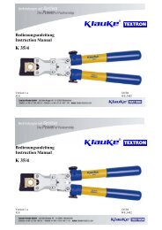
Picture 1<br />
10<br />
4<br />
3<br />
5<br />
6 2<br />
1<br />
8<br />
9<br />
7<br />
Picture 3<br />
Picture 4<br />
Crimping direction<br />
First crimp<br />
Side a<br />
Crimping direction<br />
Side b<br />
First crimp<br />
Crimping direction<br />
Side a<br />
First crimp<br />
Side b<br />
Picture 2
<strong>Instruction</strong> <strong>Manual</strong> EK 12040 page 3<br />
__________________________________________________________________________________________________________________<br />
<strong>Instruction</strong> <strong>Manual</strong><br />
for the electric-hydraulic crimping unit Type EK 12040,<br />
Serial-No. 91314VA01ff.<br />
Index<br />
1 Introduction<br />
2 Labels<br />
3 Warranty<br />
4 Description of the electric-hydraulic crimping unit<br />
4.1 Description of the components<br />
4.2 Brief description of the important features of the unit<br />
4.3 Description of the light diode display<br />
5 Remarks in respect of the determined use<br />
5.1 Operation of the units<br />
5.2 Explanation of the application range<br />
5.3 Mounting instructions<br />
5.4 Service and Maintenance instructions<br />
5.5 Remarks on the use of the Battery Cartridge and Charger<br />
5.6 Storage and transport of the crimping unit.<br />
6 Troubleshooting<br />
7 Putting out of operation/waste disposal<br />
8 Technical data<br />
Symbols<br />
1. Introduction<br />
Safety warnings<br />
Please do not disregard these instructions in order to<br />
avoid human injuries and environmental damages.<br />
Operational warnings<br />
Please do not disregard them to avoid damaging the<br />
pump unit.<br />
Before starting to use the tool please read the<br />
instruction manual carefully.<br />
Use this tool exclusively for its determined use.<br />
Mounting and assembly of connecting material with the help of<br />
this tool must only be performed by specially trained personnel.<br />
The minimum age is 16 years.<br />
This instruction manual has to be carried along during the entire<br />
life span of that tool.<br />
The operator has<br />
- to guaranty the availability of the instruction manual for the<br />
user and<br />
- to make sure, that the user has read and understood the<br />
instruction manual.<br />
2. Labels<br />
On the labels fixed on the housing of the tool you’ll find the type<br />
specification name of the manufacturer and the company logo.<br />
On the opposite side of the housing you’ll find a label with a brief<br />
presentation of the scope of manageable cross-sections for copper<br />
and aluminium and the pressing force. The serial number is on<br />
the hydraulic cylinder between the crimping head and the<br />
housing. On the crimping head you’ll find a warning against<br />
possible injuries during the crimp process.<br />
3. Warranty<br />
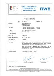
Table 1 (see Picture 1 page 2)<br />
Pos.-No. Description Function<br />
1 Trigger switch to start crimping procedure<br />
2 Retract<br />
button<br />
button to open the dies in case of<br />
emergency<br />
3 Ring device to secure the crimping tool<br />
4 Crimping C-shape crimping head for 120 kN<br />
head<br />
5 Housing ergonomically formed plastic<br />
housing for perfect handling with a<br />
detachable lid<br />
6 Light diode<br />
display<br />
indicator for tool functions and<br />
battery charge control<br />
7 Battery rechargeable NiCd battery<br />
cartridge<br />
8 Trigger lock safety lock to guarantee that no<br />
unintentional processes can occur.<br />
9 Removable<br />
hand guard<br />
guard to protect the operating<br />
hand, not for transportation<br />
10 Dies interchangeable crimping dies<br />
4.2. Brief description of the important features of the unit<br />
- The hydraulic unit incorporates an automatic retraction which<br />
returns the piston into its starting position when the maximum<br />
operating pressure is reached.<br />
- The unit is equipped with a special brake which stops the forward<br />
motion of the piston/dies when the trigger (Pos.-No. 1) is<br />
released.<br />
- The unit is equipped with a double piston pump which is<br />
characterised by a rapid approach of the dies (Pos.-No. 10)<br />
towards the connector and a slow crimping motion.<br />
- The crimping head can be smoothly turned by 360° around the<br />
longitudinal axis in order to gain better access to tight corners<br />
and other difficult working areas.<br />
- The EK 12040 is equipped with a microprocessor which<br />
indicated service intervals, internal checks and low battery<br />
charges. It also shuts off the motor automatically after the crimp<br />
is completed.<br />
4.3. Description of the light diode display<br />
This tool is equipped with a special circuit board incorporating<br />
several important features to inform the user about the current<br />
status of the unit. The diode (Pos.-No. 6) signals in the following<br />
cases:<br />
- The diode will signal periodically a few times while the battery<br />
(Pos.-No. 7) is being inserted into the tool. This indicates that the<br />
electronic circuit board performed its self-test successfully.<br />
- If the diode signals continuously after a crimping cycle for<br />
approx. 20 sec. the battery is discharged and must be recharged<br />
again.<br />
- Does the diode signal periodically at the end of a crimping cycle<br />
for approx. 20 sec the unit must be returned to an authorised<br />
Service Center for Service as soon as possible.<br />
- In case of an error the light diode display also signals periodically<br />
at the end of an pressing cycle. The signal indicates in this case<br />
the circuit opening by the electronic fuse. A possible reason for<br />
that is that a pressing cycle was performed with an incorrectly<br />
low battery. If the signal occurs even after changing the battery<br />
there must be a different error or a service is due. In these cases<br />
the tool must be returned to the manufacturer or an authorised<br />
service center.<br />
- Signal the LED (Pos.-No. 6) for 20 s continuously and then<br />
periodically a service is due and simultaneously the battery is<br />
discharged.<br />
If correct operation is guaranteed our warranty is 6 months from<br />
the time of delivery.<br />
4. Description of the electric-hydraulic crimping unit<br />
4.1. Description of the components<br />
The electric-hydraulic crimping unit type EK 12040 is a hand<br />
held tool and consists of the following components:
<strong>Instruction</strong> <strong>Manual</strong> EK 12040 page 4<br />
_______________________________________________________________________________________________________________<br />
Table 2 (see Picture 3, page 2)<br />
5. Remarks in respect of the determined use<br />
3 See picture 4 page 2<br />
Crimping Crimping Marking<br />
Surface of<br />
5.1. Operation of the unit<br />
range dies outside profile the dies<br />
mm²<br />
Before starting any work on electrical appliances it must be<br />
16-300 TCL and C. CU, „QS“ „QS“ chrome<br />
safeguarded that there are no live parts in the immediate<br />
Standard<br />
plated<br />
assembly area of the user. Is this not possible special precaution<br />
measures 1 Version<br />
(yellow)<br />
for working near live parts must be provided.<br />
16-240 TCL and C. CU, QS code # chrome<br />
DIN 46235 DIN<br />
plated<br />
Now you have to select the right dies (Pos.-No. 10) for the<br />
DIN 46267 46235<br />
intended application.<br />
10-240 Aluminium AL, „QS“ code # blue zinc<br />
Attention<br />
CL and C.<br />
Don’t operate the tool without dies.<br />
25-185 Aluminium<br />
C. Aldrey<br />
Al, „QS“ code # blue zinc<br />
The dies will be inserted sideways into the crimping head.<br />
25/4- Full tension Al, „QS“ code # blue zinc<br />
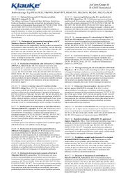
Afterwards the trigger lock (Pos.-No. 8) for the trigger (Pos.-No. 120/20 C. DIN ST, „QS“ code # black<br />
1) must be released, which means that it is pushed down (Picture<br />
2 Pos. B).<br />
10-240<br />
sm<br />
48085 T3<br />
Pre-rounding<br />
dies<br />
RU;<br />
QS, sm;<br />
- chrome<br />
plated<br />
Prior to operating the unit the charging level of the battery (Pos.-<br />
No. 7) should have been tested 2 . A low charging level can be<br />
detected by the flashing of the LED (Pos.-No. 6) for 20 s at the<br />
35-300 se<br />
16-150 Terminals<br />
DIN 46234<br />
QS, sm<br />
CU, QS<br />
DIN<br />
„QS“ chrome<br />
plated<br />
end of a crimping cycle.<br />
The crimping procedure is initiated by actuating the trigger (Pos.-<br />
10-95<br />
DIN 46230<br />
insulated<br />
terminals<br />
46234<br />
ISQ, QS „QS“ chrome<br />
plated,<br />
No. 1 & Picture 2 Pos. A). The crimping process is defined by the<br />
closing motion of the dies. During that process the connecting<br />
16-150 tub. CL for<br />
fine-str.<br />
F, QS „QS“ chrome<br />
plated<br />
material is positioned in the stationary half of the die whereas the<br />
moving part of the die is approaching the compression point 3 .<br />
4-50<br />
conductors<br />
C-clamps C, QS - chrome<br />
plated<br />
The crimping process is terminated when the crimping force is<br />
10-150 pre-insulated IS, QS „QS“ chrome<br />
reached. After having completed the crimp the dies return into<br />
tub. CL and<br />
plated<br />
the starting position automatically. Afterwards a second crimping<br />
connectors<br />
cycle can be initiated or the crimping procedure can be<br />
2x50- double compression<br />
CL<br />
plated<br />
DP, QS „QS“ chrome<br />
terminated.<br />
2x95<br />
10-95 Oval CU or AL, code # chrome<br />
Attention<br />
compression QS<br />
plated<br />
After having terminated the crimping process<br />
joints<br />
and prior to changing the dies the trigger<br />
10-185 WF DIN AE, QS - chrome<br />
(Pos.-No. 1) has to be locked with the trigger<br />
46228<br />
plated<br />
lock (Pos.-No. 8) to avoid unintended use.<br />
A bbreviations: T C L - T u b u la r cable lugs, C-Connectors, WF-Wire<br />
In case of error or emergency the dies can be returned into the<br />
F e rrules, QS-Cross-section<br />
starting position by actuating the retract button (Pos.-No. 2 &<br />
Attention<br />
Picture 2 Pos. C).<br />
Do only crimp those connecting materials mentioned<br />
in Tab. 2<br />
Attention<br />
The crimping process can be interrupted at any If different conducting materials have to be crimped, please contact<br />
moment by releasing the trigger.<br />
the manufacturer.<br />
5.2. Explanation of the application range<br />
The EK 12040 has a large number of various dies (Pos.-No. 10)<br />
available to crimp Klauke connecting material.<br />
Attention<br />
Do not crimp on live cables or conductors<br />
The EK 12040 is a hand held tool and it is not supposed to be<br />
restrained in a vise. It is not allowed to use the tool in a stationary<br />
application.<br />
The tool is not designed for continued crimping operations. After a<br />
sequence of approximately 30-40 completed crimps you have to<br />
make a break of 15 min. to give the tool time to cool down.<br />
Attention<br />
Too intensive use can cause heat damages for the<br />
tool<br />
Attention<br />
During the operation of electric engines sparks can<br />
occur which might ignite highly inflammable or<br />
explosive liquids and materials<br />
Attention<br />
Electric-hydraulic crimping tools should not be<br />
operated in pouring rain or under water.<br />
1 See EN 50110-1<br />
2 See Chapter 5.5 for more information of the battery and charging<br />
unit
<strong>Instruction</strong> <strong>Manual</strong> EK 12040 page 5<br />
_______________________________________________________________________________________________________________<br />
5.3. Mounting instructions<br />
Please read the assembly instructions in Chapter 12 of our<br />
general catalogue.<br />
Attention<br />
Even if the code number is identical only those<br />
dies should be used which are suitable for the<br />
material.<br />
Please use the following assembly instructions for cable lugs and<br />
connectors:<br />
1. Strip the conductor according to insertion depth (+10% due to<br />
the change of length of the crimped sleeve)<br />
2. The conductor ends must be cleaned with a cloth or brush<br />
before the assembly.<br />
3. Insert the conductor fully into the cable lug or connector<br />
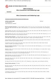
4. Pay attention to the crimping directions and use the<br />
appropriate dies. The crimping directions 3 for cable lugs and<br />
connectors is indicated in the illustration below.<br />
5. After crimping, wipe away excess compound forced out of Alcable<br />
lugs and connectors.<br />
5.4 Service and maintenance instruction<br />
The electric-hydraulic crimping unit is equipped with a<br />
sophisticated electronics enabling the user to see when the next<br />
service is due. (Pls. read chapter 4.3 for more information) When<br />
the next service is due the unit must to be returned to an<br />
authorised service center.<br />
For every day service the unit has to be cleaned and dried after<br />
each use. The battery cartridge (Pos.-No. 7) and the charging unit<br />
have to be protected against humidity and dust.<br />
Within the determined use of the tool only the dies (Pos.-No. 10)<br />
are permitted to be changed by the customers.<br />
Attention<br />
Do not damage the seals of the tool.<br />
If the seals are damaged the warranty is invalidated.<br />
5.5 Remarks on the use of the battery cartridge and charging<br />
unit.<br />
The charging unit is run with a nominal voltage of 230 V and a<br />
frequency of 50-60 Hz. New batteries must be charged prior to<br />
use. To charge the battery cartridge (Pos.-No. 7) the power plug<br />
of the charging unit has to be plugged into the power supply and<br />
the battery cartridge has to be pushed into the charging unit. The<br />
charging time is one hour. The charging level of the battery<br />
cartridge can be checked by a LED 4 .<br />
green<br />
red<br />
flashing<br />
battery cartridge is charged<br />
Battery cartridge is empty and is just being charged<br />
battery cartridge is not pushed in properly or too<br />
hot, a sound signal occurs<br />
Is the battery plugged in correctly the LED changes from green to<br />
red and the charging procedure starts. When the charging<br />
procedure is terminated the LED changes again to green.<br />
Simultaneously a signal occurs for 5 seconds.<br />
No other battery cartridges e.g. dry batteries or car batteries etc.<br />
are permitted to be used neither in the tool nor in the charging<br />
unit.<br />
As soon as the speed of the machine decreases noticeably the<br />
battery must be recharged. Do not recharge a partially empty<br />
battery as a precaution.<br />
If charging a battery which has currently been used or which was<br />
laying in the sun for a longer period of time the LED might flash<br />
red. In this case wait for a while. The charging procedure starts after<br />
the battery cooled down.<br />
Does the LED flash red and green and does an audible tone occur<br />
for 20 seconds it is not possible to charge that battery. The poles of<br />
the battery or the charging unit are dirty or the battery is low or<br />
damaged. If you want to charge two batteries in a row wait for 15<br />
min before you charge the second battery.<br />
Avoid great fluctuating temperatures under 0°C and above 40°C.<br />
Through these fluctuations damages may result for the battery<br />
cartridge as well as for the charging unit. The best operation<br />
temperature is between 15-25 °C.<br />
Do not leave or operate the charging unit in rain or snow. Do not<br />
charge the battery near lightly inflammable materials or gases.<br />
Do not use the cord to transport the charging unit or to pull the plug<br />
out of a wall socket with force. Do not insert strange parts into the<br />
ducts of the charging unit.<br />
The charging of the batteries must only be done with charging units<br />
supplied by the manufacturer.<br />
Attention<br />
Do not place the battery in your pocket or in your<br />
toolbox if there are any conductive materials in it<br />
such as coins, keys, tools or other metallic parts.<br />
Pull the plug of the charging unit after charging. Do not<br />
disassemble the charging unit or battery.<br />
In order to safeguard a safe and proper performance of the charging<br />
unit the repair and service of the unit should be made through our<br />
Service Center.<br />
5.6 Storage and transport of the crimping tool<br />
In order to protect the tool against damages it has to be cleaned<br />
carefully after each use and be put into the transportation case<br />
which has to be closed safely.<br />
6. Troubleshooting<br />
a.) Flashing of the light diode display (Pos.-No. 6)<br />
=> See chapter 4.3 for more information about the special<br />
functions of the tool.<br />
b.) The tool loses oil.<br />
=> Return the tool to the manufacturer. Do not open the tool and<br />
damage the seals of the tool.<br />
c.) The crimping tool does not reach the final operating pressure.<br />
=> Stop the crimping process. Press the retract button (Pos.-No.<br />
2) and the operating switch continuously and simultaneously for<br />
about 10 sec. Is the malfunction not be eliminated by this attempt<br />
the tool has to be returned to the manufacturer.<br />
7. Putting out of operation/waste disposal<br />
The disposal of the various components of the tool has to be treated<br />
separately. First you have to dispose of the oil at special delivery<br />
points.<br />
Attention<br />
Hydraulic oils represent a danger for the groundwater.<br />
Uncontrolled draining of or improper<br />
disposal is under penalty.<br />
(environmental liability law)<br />
Next, the battery cartridge (Pos.-No. 7) has to be specially disposed<br />
of according to the EEC Battery Guideline.<br />
For the disposal of the remaining parts please reference the EC<br />
environmental guideline.<br />
4 See Picture 4 on Page 2<br />
4 The charging level of the battery can also be verified by the LED of<br />
the tool at the end of a crimping cycle. See chapter 4.3 for further<br />
information.<br />
Because of possible environmental damages we recommend to<br />
dispose of the tool by professional companies. A return of the old<br />
tool free of charge to the manufacturer cannot be granted.
<strong>Instruction</strong> <strong>Manual</strong> EK 12040 page 6<br />
_______________________________________________________________________________________________________________<br />
8. Technical Data<br />
Weight of the complete tool: approx. 7,2 kg (incl. battery)<br />
Crimping force:<br />
approx. 120 kN<br />
Driving motor:<br />
direct-current permanent field<br />
motor<br />
Battery voltage:<br />
12 V<br />
Battery capacity<br />
2 Ah<br />
Charging time:<br />
approx. 1 h, ¼ h with<br />
Quickcharger<br />
Crimping time:<br />
approx. 12 s to 16 s<br />
(depending on the connector size)<br />
Crimp per battery: approx. 30 crimps<br />
(Cu 150 mm² DIN 46235)<br />
Hydraulic oil: approx. 190 ml "AVIA HVI 15"<br />
Environmental temperature: -20°C to –40°C<br />
Sound level:<br />
75 dB (A) in 1m distance<br />
Vibrations:<br />
< 2,5 m/s²<br />
Dimensions: See Picture 2<br />
Additional instruction manuals are available free of charge. The<br />
part # is HE.8343_B.
<strong>Instruction</strong> <strong>Manual</strong> EK 12040 page 7<br />
__________________________________________________________________________________________________________________<br />
KLAUKE TEXTRON – Service Partner international<br />
FRANKREICH:<br />
KLAUKE FRANCE<br />
Mr. Cordel<br />
16, Rue Saint-Louis<br />
Z.I. Actisud<br />
57150 Creutzwald (France)<br />
Tel.: ++33-3-87298470<br />
Fax: ++33-3-87298479<br />
E-MAIL: klauke.france@free.fr<br />
GROSSBRITTANIEN Norwich Instrument Services<br />
Mr. Norman Cockburn<br />
32 Hellesdon Park Road<br />
Drayton High Road<br />
Norwich NR6 5DR (UK)<br />
Tel.: 0044-1603-416900<br />
Fax: 0044-1603-416902<br />
E-Mail: norman@nisltd.co.uk<br />
SPANIEN/ ANDORRA:<br />
Gave Electro S.A.<br />
Mrs. Amalia<br />
Paratge Coll-Blanc, S/N<br />
Aptdo. 12<br />
08430 La Roca del Valles, Barcelona<br />
(Spanien)<br />
Tel.: ++34-93-8422212<br />
Fax: ++34-93-8422227<br />
E-MAIL: gave@gave.com<br />
TSCHECHISCHE REPUBLIK/<br />
SLOVAKEI:<br />
Jiri Nitsch<br />
M. Pujmanove 1220/31<br />
14000 Praha 4 – Prankrac<br />
(Tschechische Republik)<br />
Tel.: ++42-2-61213220<br />
Fax: ++42-2-61213218<br />
ISRAEL:<br />
ITALIEN:<br />
NIEDERLANDE:<br />
ÖSTERREICH:<br />
POLEN/ UKRAINE:<br />
PORTUGAL:<br />
SLOWENIEN:<br />
Shay A.U., Ltd.<br />
Mr. Shay<br />
Ind. Zone Kiriat Arieh<br />
Embar Street 23/25<br />
P.O. BOX 10049<br />
49222 Petach Tikva (Israel)<br />
Tel.: ++972-3-9233601<br />
Fax: ++972-3-9234601<br />
E-MAIL: a_u-shay@nezvision.net.il<br />
David Brown Hydraulics Italien S.r.l.<br />
Mrs. Albani<br />
Via del Costruttore, 64<br />
41058 Vignola (MO) (Italy)<br />
Tel.: ++39-059-7700411<br />
Fax: ++39-059-7700425<br />
E-MAIL: dbhitalia@tin.it<br />
H.K. Electric B.V.<br />
Mr. Kleijn<br />
De Ateegen 7<br />
5321 JZ Hadel (Niederlande)<br />
Tel.: ++31-73-5997599<br />
Fax: ++31-73-5997590<br />
E-Mail: hke@csi.com<br />
KLAUKE Handelsgesellschaft mbH<br />
Mr. Hruschka<br />
Kaiser-Franz-Josef-Str. 9<br />
1230 Wien (Österreich)<br />
Tel.: ++43-1-8893436<br />
Fax: ++43-1-8893433<br />
E-MAIL: office@klauke.at<br />
RB Brexim S.A.<br />
Marynin 7a<br />
05-825 Grodzisk Mazowiecki (Polen)<br />
Tel.: ++48-22-7920273 oder 75<br />
Fax: ++48-22-7923055<br />
E-MAIL: RB.office@brexim.pl<br />
Palissy Galvani Electricidade Lda.<br />
Mr. Nuno Duarte<br />
Rua Serpa Pinto, 15-A/P<br />
1200 Lisboa (Portugal)<br />
Tel.: ++351-21-3223400<br />
Fax: ++351-21-3223410<br />
Isaria d. o.o.<br />
Mrs. Zorz<br />
Proizvdnja in trgovina<br />
Cece 2a<br />
1420 Trovlje (Slowenien)<br />
Tel.: ++386-356-31800<br />
Fax: ++386-356-3180<br />
VOLKSREPUBLIK CHINA: Excellence Eng. & Trade Co,<br />
(lokaler Partner)<br />
Mr. Paul Wu<br />
Rm 1207B, T.P Plaza<br />
9/109, LiuHua Road<br />
5100010 Guagzhou (P.R. China)<br />
Tel.: ++86-20-86671150<br />
Fax: ++86-20-86671141<br />
E-MAIL: excellence@21cn.com<br />
(lokaler Partner)<br />
(Service Ansprechpartner)<br />
KOREA:<br />
Geplante (planned) Service-Center in 2002:<br />
Russland:<br />
Schweden:<br />
Beijing Tian Ze Electric Power<br />
Equipment Co.Ltd.<br />
Mr. Yu Yong<br />
Room 223-225 Juan Plaza<br />
No. 18 Bai Zi Wan Road<br />
Chao Yang District<br />
100022 Beijing (P.R. China)<br />
Tel.: ++86-10-67706841<br />
Fax: ++86-10-67718723<br />
E-MAIL: yuyong@tze.com.cn<br />
Shanghai PuHuiFeng<br />
Machinery Wquipment<br />
Maintenance Co.Ltd.<br />
Mr. Zhang Yulian<br />
No.7, 234<br />
Changning Road<br />
200042 Shanghai (China ZIP)<br />
Tel.: ++86-21-62254404<br />
Fax: ++86-21-62254404<br />
E-MAIL<br />
Taehyung Hydraulic Tool<br />
Mr. Kim<br />
140-5, Gamjeun-Dong, Sasang-Gu<br />
Busan 17-060 (Korea)<br />
Tel.: ++82-51-3171507<br />
Fax: ++82-51-3171507<br />
E-Mail: thhyd@hanmail.net