Knauf Free-Spanning Ceiling D131
Knauf Free-Spanning Ceiling D131
Knauf Free-Spanning Ceiling D131

You also want an ePaper? Increase the reach of your titles
YUMPU automatically turns print PDFs into web optimized ePapers that Google loves.
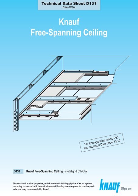
Technical Data Sheet <strong>D131</strong><br />
Edition 2005-06<br />
<strong>Knauf</strong><br />
<strong>Free</strong>-<strong>Spanning</strong> <strong>Ceiling</strong><br />
For free-spanning ceiling F90<br />
see Technical Data Sheet K219<br />
<strong>D131</strong><br />
<strong>Knauf</strong> <strong>Free</strong>-<strong>Spanning</strong> <strong>Ceiling</strong> - metal grid CW/UW<br />
The structural, statical properties, and characteristic building physics of <strong>Knauf</strong> systems<br />
can solely be ensured with the exclusive use of <strong>Knauf</strong> system components, or other products<br />
expressly recommended by <strong>Knauf</strong>.
<strong>Knauf</strong> <strong>Free</strong>-<strong>Spanning</strong> <strong>Ceiling</strong><br />
Fire protection from below / from below and from above (plenum)<br />
<strong>Ceiling</strong>s that are fire protection rated on its own<br />
Requirement to the basic ceiling<br />
for fire protection:<br />
from below<br />
no fire protection requirements<br />
to basic ceiling / roof construction<br />
from above (plenum)<br />
the basic ceiling should have<br />
the same fire protection rate<br />
as the underceiling<br />
Fire protection<br />
rate for<br />
fire stress from<br />
below<br />
above<br />
<strong>Knauf</strong> System Constructions<br />
cladding<br />
minimum<br />
thick-<br />
ness<br />
type/<br />
building<br />
material<br />
class<br />
mm<br />
metal<br />
grid<br />
max. spacing<br />
of C profiles<br />
b<br />
mm<br />
insulation<br />
(required<br />
for fire protection)<br />
min.<br />
thickness<br />
mm<br />
minimum<br />
density<br />
kg/m³<br />
<strong>D131</strong><br />
Proof<br />
<strong>D131</strong> <strong>Free</strong>-<strong>Spanning</strong> <strong>Ceiling</strong><br />
solely from below<br />
18 625<br />
mineral wool<br />
40 -<br />
G<br />
F30<br />
Fire-Resistant<br />
Boards<br />
GKF, A2<br />
25 625<br />
without insulation<br />
or<br />
min. B2<br />
ABP<br />
P-3964/2172<br />
2x 12.5 500<br />
<strong>D131</strong> <strong>Free</strong>-<strong>Spanning</strong> <strong>Ceiling</strong><br />
solely from below and from above<br />
cover strips GKF 25 mm<br />
F30<br />
F30<br />
Fire-Resistant<br />
Boards 18 625<br />
GKF, A2<br />
mineral wool S<br />
40 40<br />
or<br />
60 30<br />
ABP<br />
P-3964/2172<br />
cover strips GKF 25 mm<br />
F30<br />
F30<br />
Fire-Resistant 18<br />
Boards + 625<br />
GKF, A2 12.5<br />
covering layer<br />
without insulation<br />
or<br />
min. B2<br />
ABP<br />
P-3964/2172<br />
Flanking components should have a fire protection rate of F30.<br />
Mineral wool insulation according to DIN EN 13162, chapter 3.1.1<br />
building material class A<br />
S melting point 1000° C, G building material class A<br />
according to DIN 4102-17<br />
2<br />
Note <strong>Free</strong>-<strong>Spanning</strong> Fireboard <strong>Ceiling</strong> A1: F90 solely from below; F90 solely from below and from above - see TDS K219
<strong>Knauf</strong> <strong>Free</strong>-<strong>Spanning</strong> <strong>Ceiling</strong><br />
Fastening<br />
Fastening of load bearing perimeter runners<br />
Fastening to<br />
Anchor<br />
Maximum<br />
spacing of<br />
anchors<br />
<strong>D131</strong><br />
metal stud partitions<br />
(fastening to metal studs)<br />
reinforced concrete walls<br />
substantial masonry<br />
without cavities or<br />
light concrete (density 1000 kg/m³)<br />
other materials<br />
2x <strong>Knauf</strong> All Purpose Screw FN 4.3x35<br />
2x <strong>Knauf</strong> All Purpose Screw FN 4.3x65<br />
<strong>Knauf</strong> <strong>Ceiling</strong> Steel Dowel<br />
<strong>Knauf</strong> Nailable Plug L 8/80<br />
<strong>Knauf</strong> Nailable Plug L 8/80<br />
suitable anchors<br />
minumum shear load capacity 0.35 kN per anchor<br />
625 mm<br />
300 mm<br />
For room widths 2.25 m the number of anchors can be reduced by 50 % respectively the spacing of the anchors can be doubled.<br />
Connections to partitions<br />
<strong>Knauf</strong> single or double CW profiles<br />
Screwing of <strong>Knauf</strong> CW double profiles<br />
750 mm<br />
625 mm<br />
30 mm<br />
<strong>Knauf</strong> UW runner<br />
<strong>Knauf</strong> CW double profiles with cover strip<br />
625 mm<br />
Connect <strong>Knauf</strong> CW profiles as<br />
single or double profiles (per flange)<br />
with UW runner by riveting,<br />
crimping or screwing with <strong>Knauf</strong><br />
Metal Screws LB 3.5x9.5 mm.<br />
cover strip GKF 25 mm<br />
120 mm wide<br />
screw <strong>Knauf</strong> CW profiles at web<br />
with metal screw LB 3.5x9.5 mm<br />
at a spacing of 750 mm<br />
Alternating screwing<br />
cover strip / cladding<br />
cover strip GKF 25 mm, 120 mm wide<br />
<strong>Knauf</strong> Drywall<br />
250<br />
Screw TN 3.5x35<br />
cladding<br />
170<br />
500 mm<br />
<strong>Knauf</strong> CW double profile<br />
cut edge joint<br />
30 mm<br />
<strong>Knauf</strong> UW runner<br />
<strong>Knauf</strong> CW double profile<br />
170<br />
340 mm<br />
3
<strong>Knauf</strong> <strong>Free</strong>-<strong>Spanning</strong> <strong>Ceiling</strong><br />
Without fire protection<br />
<strong>D131</strong><br />
Cladding GKB<br />
12.5 mm<br />
or<br />
2x 12.5 mm<br />
or<br />
18 mm<br />
A<br />
A<br />
Screws<br />
b<br />
C<br />
<strong>Knauf</strong> Drywall<br />
Screws<br />
single layer cladding<br />
12.5 mm TN 3.5x25<br />
18 mm TN 3.5x35<br />
double layer cladding<br />
1st layer: TN 3.5x25<br />
2nd layer: TN 3.5x35<br />
Maximum<br />
spacing<br />
of screws<br />
170 mm<br />
500 mm<br />
170 mm<br />
maximum room width 5,5 m<br />
C<br />
Maximum room width in m<br />
<strong>Knauf</strong> CW profile <strong>Knauf</strong> CW profile<br />
as load bearing<br />
<strong>Knauf</strong> CW double profile<br />
as load bearing<br />
<strong>Knauf</strong> UW runner<br />
as perimeter<br />
channel channel connection<br />
metal thickness<br />
0.6 mm<br />
max. room width<br />
max. room width<br />
at max. spacing of profiles b at max. spacing of profiles b<br />
500 mm 500 mm 625 mm<br />
cladding<br />
cladding<br />
12.5 mm 2x 12.5 mm 12.5 mm<br />
2x 12.5 mm<br />
metal thickness<br />
0.6 mm<br />
CW 50<br />
CW 75<br />
CW 100<br />
CW 125<br />
2.5<br />
3.25<br />
3.75<br />
4.25<br />
2.25<br />
2.75<br />
3.25<br />
3.75<br />
3<br />
3.75<br />
4.25<br />
5<br />
2.5<br />
3.25<br />
3.75<br />
4.25<br />
2.75<br />
3.25<br />
4<br />
4.5<br />
UW 50<br />
UW 75<br />
UW 100<br />
UW 125<br />
CW 150 4.75 4.25<br />
5.5<br />
4.75<br />
5<br />
UW 150<br />
Details scale 1:5<br />
18 mm<br />
connect free-spanning<br />
<strong>Knauf</strong> CW profile<br />
to UW runner<br />
by riveting,<br />
<strong>Knauf</strong> CW profile<br />
crimping or with<br />
Metal Screws<br />
<strong>Knauf</strong> UW runner,<br />
e.g. LB 3.5x9.5<br />
fastening according to page 3<br />
<strong>Knauf</strong> CW profile as connect<br />
load bearing channel free-spanning<br />
CW double profile<br />
(per flange)<br />
UW runner<br />
to UW runner<br />
as perimeter<br />
by riveting, crimping<br />
connection<br />
or with Metal Screws<br />
e.g. LB 3.5x9.5<br />
<strong>Knauf</strong> CW double profile<br />
as load bearing channel<br />
Metal Screw<br />
LB 3.5x9.5<br />
a 750 mm<br />
75 mm<br />
62.5 mm<br />
68 mm<br />
<strong>Knauf</strong> Boards 2x 12.5 mm <strong>Knauf</strong> Board 12.5 mm <strong>Knauf</strong> Board 18 mm<br />
500 mm<br />
b<br />
b<br />
500 mm<br />
500 mm<br />
b<br />
b<br />
625 mm<br />
625 mm<br />
b<br />
4<br />
<strong>D131</strong>-A1<br />
Structural<br />
connection to partition<br />
<strong>D131</strong>-C1<br />
Cut edge joint<br />
single profile<br />
<strong>D131</strong>-C2<br />
Cut edge joint<br />
double profile
<strong>Knauf</strong> <strong>Free</strong>-<strong>Spanning</strong> <strong>Ceiling</strong><br />
Fire protection<br />
Cladding GKF<br />
18 mm<br />
mineral wool insulation<br />
according to<br />
DIN EN 13162,<br />
chapter 3.1.1<br />
building material<br />
class A<br />
thickness 40 mm<br />
Screws<br />
<strong>Knauf</strong> Drywall<br />
Screws<br />
single layer cladding<br />
TN 3.5x35<br />
double layer cladding<br />
1st layer: TN 3.5x25<br />
2nd layer: TN 3.5x35<br />
<strong>Knauf</strong> CW double profile<br />
as load bearing channel<br />
metal thickness 0.6 mm<br />
25 / 2x 12.5 mm<br />
without insulation<br />
or min. B2<br />
Max.<br />
spacing<br />
of screws<br />
170 mm<br />
500 mm<br />
170 mm<br />
Maximum room width in m<br />
2x CW 50<br />
2x CW 75<br />
2x CW 100<br />
2x CW 125<br />
2x CW 150<br />
● solely from below<br />
Max. spacing of<br />
profiles<br />
b<br />
D<br />
Cladding<br />
625 mm<br />
18 / 25 mm<br />
500 mm 2x 12.5 mm<br />
D<br />
b<br />
min. thickness<br />
B<br />
max. room width 4.75 m<br />
B<br />
Maximum room width in m<br />
in case of additional<br />
exposed ceiling (s. pg. 7)<br />
(max. 0.15 kN/m²)<br />
2.25 2<br />
3<br />
2.75<br />
3.5<br />
3.25<br />
4<br />
3.5<br />
4.75 4<br />
C<br />
C<br />
A<br />
A<br />
<strong>D131</strong><br />
<strong>Knauf</strong> UW runner<br />
as perimeter connection<br />
metal thickness 0.6 mm<br />
UW 50<br />
UW 75<br />
UW 100<br />
UW 125<br />
UW 150<br />
Details scale 1:5<br />
<strong>Knauf</strong> UW runner connected to<br />
metal stud of partition with<br />
<strong>Knauf</strong> All Purpose Screws 2x FN 4.3x35 (according to pg. 3)<br />
<strong>Knauf</strong> CW double profile<br />
as load bearing channel<br />
<strong>D131</strong>vu-D1 partition<br />
<strong>Knauf</strong> Solid Board 25 mm<br />
max. room width<br />
<strong>Knauf</strong> Solid Board 25 mm<br />
Load bearing<br />
connection to<br />
<strong>D131</strong>vu-B1 Longitudinal edge joint<br />
connect free-spanning CW double profile <strong>Knauf</strong> CW double profile<br />
<strong>Knauf</strong> CW profile<br />
(per flange) to UW runner as load bearing channel<br />
by riveting, crimping or with Metal Screws<br />
<strong>Knauf</strong> UW runner, fastening according to page 3<br />
e.g. LB 3.5x9.5<br />
<strong>Knauf</strong> UW runner<br />
as perimeter connection<br />
mineral wool<br />
building material class A<br />
min. thickness 40 mm<br />
(required for<br />
fire protection)<br />
<strong>Knauf</strong> Board GKF 18 mm<br />
500 mm b<br />
<strong>Knauf</strong> Boards GKF<br />
2x 12.5 mm<br />
b 625 mm 625 mm b<br />
<strong>D131</strong>vu-A1<br />
Structural<br />
connection to partition<br />
<strong>D131</strong>vu-C1 Cut edge joint<br />
75 mm<br />
<strong>Knauf</strong> CW double profile<br />
as load bearing profile<br />
68 mm 75 mm<br />
5
<strong>Knauf</strong> <strong>Free</strong>-<strong>Spanning</strong> <strong>Ceiling</strong><br />
Fire protection F30 ● solely from below and from above<br />
<strong>D131</strong><br />
A<br />
b<br />
C<br />
b<br />
A<br />
D<br />
D<br />
C B B<br />
max. room width 4 m max. room width 4 m<br />
Mineral wool insulation<br />
S<br />
according to DIN EN 13162, chapter 3.1.1 building material class A,<br />
melting point 1000°C (1832°F), according to DIN 4102-17<br />
thickness: 60 mm; density: 30 kg/m³ or<br />
thickness: 40 mm; density: 40 kg/m³<br />
Additional layer: 12.5 mm GKF<br />
applied loose with tight joints<br />
complete covering of <strong>Knauf</strong> CW profiles<br />
including cover strips<br />
Cladding<br />
Cover strip<br />
Max. spacing of <strong>Knauf</strong> Drywall Screws TN 3.5x35<br />
18 mm GKF<br />
25 mm GKF<br />
b 120 mm<br />
cladding<br />
cover strip<br />
170 mm<br />
250 mm<br />
Maximum room width in m<br />
<strong>Knauf</strong> CW double profile<br />
as load bearing channel<br />
metal thickness 0.6 mm<br />
Max. spacing of<br />
profiles<br />
b<br />
Cladding<br />
min. thickness<br />
Maximum room width in m<br />
<strong>Knauf</strong> UW runner<br />
in case of additional as perimeter connection<br />
exposed ceiling<br />
(max. 0.15 kN/m²)<br />
(see pg. 7)<br />
metal thickness 0.6 mm<br />
2x CW 50<br />
2x CW 75<br />
2x CW 100<br />
2x CW 125<br />
625 mm<br />
18 mm<br />
2.25<br />
3<br />
3.5<br />
4<br />
2<br />
2.75<br />
3.25<br />
3.5<br />
UW 75<br />
UW 100<br />
UW 125<br />
UW 150<br />
Details scale 1:5<br />
60 mm<br />
complete covering with<br />
<strong>Knauf</strong> Boards GKF 12.5 mm<br />
<strong>Knauf</strong> CW profile<br />
<strong>Knauf</strong> UW runner<br />
fastening according to page 3<br />
625 mm b<br />
Structural connection to partition<br />
<strong>D131</strong>vuvo-A2<br />
with additional layer, without insulation<br />
<strong>Knauf</strong> All Purpose Screw 2x FN 4.3x35<br />
fastened to metal stud of partition<br />
cover strip GKF 25 mm<br />
120 mm wide<br />
<strong>Knauf</strong> CW double profile<br />
as load bearing channel<br />
<strong>Knauf</strong> Board GKF 18 mm<br />
cover strip GKF<br />
25 mm, 120 mm wide<br />
<strong>D131</strong>vuvo-B2<br />
10<br />
105.5 mm<br />
Longitudinal edge joint with<br />
additional layer, without insulation<br />
120 mm<br />
<strong>Knauf</strong> UW runner<br />
10<br />
100<br />
as wall<br />
connection<br />
mineral wool S<br />
60 mm; 30 kg/m³<br />
or<br />
40 mm; 40 kg/m³<br />
93 mm<br />
6<br />
<strong>Knauf</strong> UW runner<br />
<strong>Knauf</strong> CW double profile<br />
as load bearing channel<br />
max. room width<br />
Load bearing connection to partition<br />
<strong>D131</strong>vuvo-D1<br />
with insulation<br />
b 625 mm 625 mm b<br />
Cut edge joint<br />
<strong>D131</strong>vuvo-C1<br />
with insulation<br />
<strong>Knauf</strong> Board GKF 18 mm
<strong>Knauf</strong> <strong>Ceiling</strong> below <strong>Ceiling</strong><br />
<strong>Knauf</strong> Apertura Acoustical <strong>Ceiling</strong> below <strong>Free</strong>-<strong>Spanning</strong> <strong>Ceiling</strong> <strong>D131</strong><br />
<strong>D131</strong><br />
<strong>Free</strong>-<strong>Spanning</strong> <strong>Ceiling</strong> <strong>D131</strong><br />
as fire protection ceiling<br />
F30<br />
solely from below<br />
1<br />
solely from below<br />
and from above<br />
Example:<br />
fire protection<br />
F30<br />
solely from below<br />
and from above<br />
a<br />
suspender spacing of exposed ceiling<br />
1<br />
Proof:<br />
ABP P-3964/2172<br />
2<br />
Exposed ceiling<br />
0.15 kN/m²<br />
e.g. Acoustical <strong>Ceiling</strong><br />
insulation (building<br />
material class A) allowable<br />
2<br />
b<br />
spacing of lower channels<br />
b<br />
c<br />
spacing of upper channels<br />
<strong>Free</strong>-<strong>Spanning</strong> <strong>Ceiling</strong> as fire protection ceiling<br />
The additional dead load of the exposed ceiling<br />
( 0.15 kN/m²) has to be considered for the maximum<br />
ceiling span (room width) of the <strong>Free</strong>-<strong>Spanning</strong> <strong>Ceiling</strong>.<br />
Maximum room widths can be taken from the tables<br />
on pages 5 and 6.<br />
Detail scale 1:5<br />
1<br />
Maximum spacings of exposed ceiling 2 all dimension in mm<br />
Maximum Maximum spacing Maximum<br />
spacing of c suspenders *) a spacing of b<br />
upper channels<br />
load bearing capacity class<br />
lower channel<br />
up to 0.15 kN/m²<br />
1000<br />
1200<br />
625<br />
500<br />
500<br />
(for Acoustical<br />
<strong>Ceiling</strong>s see D12)<br />
*) Suspension must be fastened to load bearing channels of the fire protection ceiling.<br />
fastening of UW runner to wall according to page 3<br />
<strong>Knauf</strong> CW double profile<br />
<strong>Knauf</strong> All Purpose Screw FN<br />
Universal Bracket for CD 60x27<br />
(install alternating)<br />
<strong>D131</strong>-D112<br />
<strong>Knauf</strong> Board<br />
2 1<br />
<strong>Knauf</strong> Exposed <strong>Ceiling</strong> below <strong>Free</strong>-<strong>Spanning</strong> <strong>Ceiling</strong><br />
1st <strong>Ceiling</strong> level 1<br />
<strong>Free</strong>-<strong>Spanning</strong> <strong>Ceiling</strong> <strong>D131</strong><br />
as fire protection ceiling<br />
2nd <strong>Ceiling</strong> level<br />
exposed ceiling<br />
0.15 kN/m²<br />
alternative suspension:<br />
Direct Bracket<br />
2<br />
example:<br />
fire protection<br />
F30<br />
solely from below<br />
Note<br />
References<br />
upper channels of exposed ceiling always lateral to load bearing channels of <strong>Free</strong>-<strong>Spanning</strong> <strong>Ceiling</strong><br />
loading of exposed ceiling max. 100 N per suspender<br />
Technical Data Sheet D12 <strong>Knauf</strong> Acoustical <strong>Ceiling</strong>s<br />
7
<strong>Knauf</strong> <strong>Free</strong>-<strong>Spanning</strong> <strong>Ceiling</strong><br />
Control joints, ceiling plan, settlement joint, <strong>Ceiling</strong> Bulkhead<br />
Details scale 1:5<br />
Examples: Fire Protection F30 solely from below and from above with insulation<br />
<strong>D131</strong><br />
board strip GKF 25 mm<br />
Drywall Screw TN 3.5x35 mm<br />
board strip GKF 25 mm<br />
<strong>Knauf</strong> Nailable Plug L8/80<br />
20 mm<br />
5<br />
<strong>D131</strong>-SO-A1<br />
<strong>Knauf</strong> CW profile <strong>Knauf</strong> UW runner<br />
Connection to solid wall<br />
with shadow gap<br />
Edge Trim if necessary<br />
e.g. <strong>Knauf</strong> Fugenfüller Leicht<br />
<strong>D131</strong>-SO-D1<br />
5<br />
20 mm<br />
Connection to solid wall<br />
with shadow gap<br />
D1<br />
D1<br />
B2<br />
A1<br />
A1<br />
<strong>Knauf</strong> CW double profile<br />
C1<br />
C1<br />
lighting<br />
B1<br />
B1<br />
C2<br />
Access Panel<br />
C2<br />
C3<br />
C3<br />
A2<br />
A2<br />
max. room width<br />
B2<br />
<strong>Ceiling</strong> plan<br />
Details lighting and access panel see page 9<br />
cover strip GKF 25 mm<br />
board strip<br />
GKF 18 mm<br />
glued with <strong>Knauf</strong><br />
Fugenfüller Leicht<br />
on one side<br />
25<br />
100 mm<br />
a<br />
25<br />
a<br />
100 mm<br />
<strong>Knauf</strong> Board GKF 18 mm<br />
Edge Trim if<br />
necessary<br />
a 20 mm<br />
<strong>Knauf</strong> Board GKF 18 mm<br />
<strong>Knauf</strong> All Purpose Screw<br />
FN 4.3x35, screwed into<br />
metal profile of ceiling bulkhead<br />
ceiling bulkhead<br />
fire protection F30<br />
installation according to<br />
Technical Data Sheet D16<br />
<strong>Knauf</strong> <strong>Ceiling</strong> Built-ins<br />
8<br />
<strong>D131</strong>-SO-C3<br />
Settlement joint<br />
<strong>D131</strong>-SO-A2<br />
<strong>Ceiling</strong> bulkhead
<strong>Knauf</strong> <strong>Free</strong>-<strong>Spanning</strong> <strong>Ceiling</strong><br />
Lighting fixtures, access panel<br />
Details scale 1:5<br />
Fire protection covering of lighting fixtures is possible for <strong>Knauf</strong> <strong>Free</strong>-<strong>Spanning</strong> <strong>Ceiling</strong>s<br />
<strong>D131</strong><br />
<strong>D131</strong>-SO-C1<br />
Access Panel<br />
steel brackets<br />
according to DIN 18182<br />
additional profile<br />
(not necessary for openings<br />
up to 200 mm width)<br />
625 mm<br />
25<br />
400 mm<br />
covering 400 x 1000 mm<br />
made of <strong>Knauf</strong> Boards GKF 25 mm<br />
fixing of lighting<br />
fixture according<br />
to manufacturers<br />
instructions<br />
Lateral section lighting fixture<br />
example: F30 solely from below<br />
height 25<br />
of lighting box<br />
steel brackets<br />
according to DIN 18182<br />
<strong>D131</strong>-SO-B1<br />
25<br />
1000 mm<br />
covering<br />
400 x 1000 mm<br />
made of <strong>Knauf</strong> Boards<br />
GKF 25 mm<br />
fixing of lighting<br />
fixture according<br />
to manufacturers<br />
instructions<br />
Longitudinal section lighting<br />
fixture<br />
example: F30 solely from below<br />
<strong>D131</strong>-SO-C2<br />
Lateral section<br />
access panel<br />
Example:<br />
F30 solely from below<br />
and from above<br />
complete covering with<br />
<strong>Knauf</strong> Boards GKF 12.5 mm<br />
without insulation, with<br />
additional layer<br />
complete covering with<br />
<strong>Knauf</strong> Boards GKF 12.5 mm<br />
6<br />
<strong>Knauf</strong> UW runner<br />
625 mm<br />
board strips GKF 12.5 mm fastened to<br />
UW runner with<br />
Drywall Screws TN 3.5x25<br />
clearance<br />
450 mm<br />
board strips GKF 12.5 mm fastened to<br />
<strong>Knauf</strong> CW profile with Drywall Screws<br />
TN 3.5x25 and TN 3.5x35<br />
Alutop Access<br />
Panel<br />
6<br />
Drywall Screw TB 3.5x35<br />
at a spacing of 170 mm<br />
with insulation<br />
<strong>D131</strong>-SO-B2<br />
Longitudinal section<br />
access panel<br />
Example:<br />
F30 solely from below<br />
and from above<br />
without insulation, with<br />
additional layer<br />
Alutop Access Panel<br />
6 clearance<br />
6<br />
1500 mm<br />
Drywall Screw TB 3.5x35<br />
at a spacing of 170 mm<br />
with insulation<br />
Alutop Access Panel<br />
Standard dimensions<br />
clearance<br />
450 mm x 1500 mm<br />
450 mm x 450 mm<br />
in-between sizes on request<br />
Alutop Access Panel can be<br />
hung out completely<br />
9
<strong>Knauf</strong> <strong>Free</strong>-<strong>Spanning</strong> <strong>Ceiling</strong><br />
Material requirements<br />
of selected examples<br />
<strong>D131</strong><br />
Material requirement per m² ceiling area without addition for loss and waste.<br />
description<br />
external material = printed italic<br />
unit<br />
(Amounts refer to a ceiling area of 2.5 m x 10 m = 25 m²)<br />
amount as average value<br />
without<br />
fire protection<br />
<strong>Knauf</strong> Boards<br />
GKB 12.5 mm<br />
spacing of<br />
channels 500 mm<br />
fire protection<br />
solely from below<br />
<strong>Knauf</strong> Boards GKF 18 mm<br />
spacing of channels 625 mm<br />
fire prot. solely from below + from above<br />
with insulation without insulation<br />
10<br />
connection to wall<br />
UW runner 50x40x0.6; (4.0 m long)<br />
resp.<br />
UW runner 75x40x0.6; (4.0 m long)<br />
resp.<br />
UW runner 100x40x0.6; (4.0 m long)<br />
resp.<br />
UW runner 125x40x0.6; (special)<br />
UW runner 150x40x0.6; (special)<br />
CW profile 50x50x0.6; (up to 5.0 m long)<br />
resp.<br />
CW profile 75x50x0.6; (up to 6.0 m long)<br />
resp.<br />
CW profile 100x50x0.6; (up to 6.0 m long)<br />
resp.<br />
CW profile 125x50x0.6; (special)<br />
resp.<br />
CW profile 150x50x0.6; (special)<br />
fastening of perimeter runner:<br />
resp.<br />
<strong>Knauf</strong> All Purpose Screw FN 4.3x35<br />
<strong>Knauf</strong> All Purpose Screw FN 4.3x65<br />
resp.<br />
<strong>Knauf</strong> Nailable Plug "L" 8/80; (50 pcs. box)<br />
resp.<br />
<strong>Knauf</strong> Nailable Plug; (100 pcs. box)<br />
connection double profile to perimeter runner<br />
e.g. 2x metal rivets<br />
metal grid<br />
<strong>Knauf</strong> CW double profile as load bearing channels:<br />
2x CW profile 50x50x0.6; (up to 5.0 m long)<br />
resp.<br />
2x CW profile 75x50x0.6; (up to 6.0 m long)<br />
resp.<br />
2x CW profile 100x50x0.6; (up to 6.0 m long)<br />
resp.<br />
2x CW profile 125x50x0.6; (special)<br />
resp.<br />
2x CW profile 150x50x0.6; (special)<br />
<strong>Knauf</strong> CW double profile screwed at flange:<br />
<strong>Knauf</strong> Metal Screw LB 3.5 x 9.5 mm<br />
insulation (consider fire protection; see page 2)<br />
cladding<br />
<strong>Knauf</strong> Board GKB; 12.5 mm<br />
resp.<br />
<strong>Knauf</strong> Fire-Resistant Board GKF; 18 mm<br />
cover strip 120 mm wide:<br />
<strong>Knauf</strong> Solid Board GKF; 25 mm<br />
additional layer:<br />
<strong>Knauf</strong> Fire-Resistant Board GKF; 12.5 mm<br />
<strong>Knauf</strong> Drywall Screws; (fastening of cover strips)<br />
TN 3.5 x 35 mm<br />
<strong>Knauf</strong> Drywall Screws; (fastening of cladding)<br />
TN 3.5 x 25 mm<br />
TN 3.5 x 35 mm<br />
joint filling<br />
<strong>Knauf</strong> Uniflott; (5 kg/25 kg bag)<br />
(for hand filling)<br />
or<br />
<strong>Knauf</strong> Jointfiller Super; (20 kg bag)<br />
(for machine filling with Ames Machine)<br />
or<br />
<strong>Knauf</strong> Fugenfüller Leicht; (5 kg/10 kg/25 kg bag)<br />
(for hand filling with joint tape)<br />
<strong>Knauf</strong> Joint Tape; (23 m/75 m/150 m roll)<br />
Trenn-Fix 65; (50 m roll)<br />
Edge Trim 23/15; (2.75 m long)<br />
m<br />
m<br />
pcs<br />
pcs<br />
m 3.8<br />
pcs 3.0<br />
m²<br />
m²<br />
m² -<br />
m²<br />
pcs<br />
pcs<br />
kg<br />
kg<br />
kg<br />
m<br />
m<br />
m<br />
0.8 0.8<br />
0.8 0.8<br />
0.2 0.2<br />
0.2<br />
0.2<br />
3.2<br />
as required<br />
1.0<br />
-<br />
-<br />
-<br />
19<br />
-<br />
0.3<br />
0.4<br />
0.3<br />
0.35<br />
1.0<br />
as required<br />
2.6<br />
3.0<br />
- -<br />
- 0.2<br />
0.2<br />
-<br />
3.0 3.0<br />
2.4 2.4 2.4<br />
as required 1.0<br />
as required<br />
-<br />
1.0<br />
- -<br />
- -<br />
1.0<br />
1.0<br />
1.0<br />
10 10<br />
- - -<br />
17<br />
17 17<br />
0.4<br />
0.5<br />
- -<br />
- -<br />
3.1 3.1 3.1 3.1<br />
- -<br />
0.4<br />
0.5<br />
0.4<br />
0.5<br />
0.4 0.4 0.4<br />
0.35<br />
0.35<br />
0.35<br />
1.0<br />
1.0<br />
1.0<br />
as required as required as required
<strong>Knauf</strong> <strong>Free</strong>-<strong>Spanning</strong> <strong>Ceiling</strong><br />
Specifications<br />
<strong>D131</strong><br />
Item Description No. of units Unit price Total price<br />
........ <strong>Ceiling</strong> DIN 18168-1, installation height in m ....................,<br />
ceiling span of free-spanning ceiling in m .............................,<br />
fi re resistance class according to DIN 4102-2 F 30,*<br />
for the ceiling solely resistant to fi re from below<br />
to protect the basic ceiling and the plenum, */<br />
for the ceiling solely resistant to fi re from<br />
the plenum to protect the room below the ceiling, */<br />
for the ceiling solely resistant to fi re from<br />
the plenum and from below to protect the room below the ceiling,<br />
the basic ceiling and the plenum, *<br />
anchored on reinforced concrete/ masonry/<br />
metal stud partition/ wood frame partition/ ..........................., *<br />
metal grid made of galvanized metal channels,<br />
load bearing channels as single/ double * CW profi les CW 50/ 75/ 100/ 125/ 150 *.<br />
cladding made of <strong>Knauf</strong> Boards GKB/ GKF *, thickness 12.5/ 18/ 25/ 2x12.5 mm *.<br />
additional cladding made of <strong>Knauf</strong> Boards GKF, thickness 12.5 mm. *<br />
insulation made of mineral wool according to DIN EN 13162/ made of ........................ *,<br />
thickness in mm ..............., minimum density in kg/ m³ ..................., *<br />
building material class A/ B1/ B2 *, melting point min. 1000°C (1832°F). *<br />
Product/ System: <strong>Knauf</strong> <strong>Free</strong>-<strong>Spanning</strong> <strong>Ceiling</strong> <strong>D131</strong> .......... m² .......... € .......... €<br />
........ <strong>Ceiling</strong> DIN 18168-1 as decribed above, with additional exposed ceiling.<br />
sound absorption coeffi cient according to DIN EN 20354 ............................................. *<br />
installation of acoustical ceiling with lower and upper channels,<br />
suspend with Universal Bracket to load bearing channels of <strong>Free</strong>-<strong>Spanning</strong> <strong>Ceiling</strong> <strong>D131</strong>,<br />
plenum damping with mineral wool, thickness min. 20 mm, *<br />
cladding made of <strong>Knauf</strong> Apertura Boards DIN 18180, board thickness 12.5 mm,<br />
perforation standard circular R: 6/18 R/ 8/18 R/ 10/23 R/ 12/25 R/ 15/30 R */<br />
perforation alternating circular R: 8/12/50/ 12/20/66 * R/<br />
perforation random Plus R: 8/15/20 R/ 12/20/35 R */ standard square Q: 8/18 Q, 12/25 Q *.<br />
Product/ System: <strong>Knauf</strong> Acoustical <strong>Ceiling</strong> D127 below <strong>Free</strong>-<strong>Spanning</strong> <strong>Ceiling</strong> <strong>D131</strong> .......... m² .......... € .......... €<br />
........ Connection with joint, fi re resistance ...................*,<br />
for free-spanning ceiling, circumferential, installation according to drawing no.. ............... .......... m .......... € .......... €<br />
........ Control joint, fi re resistance ...................*,<br />
as upgrade to free-spanning ceiling, installation according to drawing no.. ............... .......... m .......... € .......... €<br />
........ Settlement joint, fi re resistance ...................*,<br />
as upgrade to free-spanning ceiling, installation according to drawing no.. ............... .......... m .......... € .......... €<br />
........ <strong>Ceiling</strong> bulkhead/ ceiling protrusion *, height in m .................,<br />
fi re resistance ...................*,<br />
as upgrade to free-spanning ceiling, installation according to drawing no.. ............... .......... m .......... € .......... €<br />
........ Cutout, as upgrade to free-spanning ceiling,<br />
diameter in mm .................../ dimensions in mm ....................... * ........ pcs .......... € .......... €<br />
........ Opening including reinforcement of metal grid,<br />
for lighting fi xtures/ ....................... *.<br />
as upgrade to free-spanning ceiling, dimensions in mm ...........................,<br />
installation according to drawing no.. ............... . ........ pcs .......... € .......... €<br />
........ Fire protection covering for built-in lighting fi xtures,<br />
fi re resistance ...................*,<br />
dimensions in mm ......................., installation according to drawing no.. ............... . ........ pcs .......... € .......... €<br />
........ Access panel, installation according to drawing no.. ............... .*,<br />
frame made of aluminium, dimensions in mm ....................,<br />
panel fi lling made of <strong>Knauf</strong> Boards, thickness in mm ................. ,<br />
with extension-rod safety latch and non-visible lock and hinge system.<br />
for <strong>Knauf</strong> <strong>Free</strong>-<strong>Spanning</strong> <strong>Ceiling</strong> <strong>D131</strong>.<br />
Product: <strong>Knauf</strong> Access Panel D171 ........ pcs .......... € .......... €<br />
........ Additional fi lling of connections to built-ins. .......... m .......... € .......... €<br />
* Cancel not applicable items Sub-total ................ €<br />
11
<strong>Knauf</strong> <strong>Free</strong>-<strong>Spanning</strong> <strong>Ceiling</strong><br />
Construction and application, jointing, surface treatment<br />
<strong>D131</strong><br />
Construction<br />
<strong>Knauf</strong> <strong>Free</strong>-<strong>Spanning</strong> <strong>Ceiling</strong>s are solely fastened<br />
to the walls at perimeter. <strong>Knauf</strong> Boards<br />
GKB/ GKBI impregnated, Fire-Resistant Boards<br />
GKF/ GKFI or LaVita Shielding Boards are<br />
screwed to a metal grid made of <strong>Knauf</strong> CW profi<br />
les as single or double profi les.<br />
The application of additional loads like lighting fi x-<br />
tures with max. 100 N (10 kg) per double profi le<br />
and exposed ceilings like e.g. D127 <strong>Knauf</strong> Apertura<br />
Acoustical <strong>Ceiling</strong> with load per unit area of<br />
Application<br />
Metal Grid<br />
● Perimeter connection to walls with UW runners.<br />
Fastening according to table page 3 at<br />
centers of ≤ 625 mm.<br />
● For sound protection requirements seal up<br />
carefully with acoustical sealant according to<br />
DIN 4109, supplement 1, chapter 5.2; porous<br />
sealant strips like Sealing Tape are usually not<br />
suitable in this case.<br />
● CW profi les as double profi les are screwed at<br />
web with metal screws LB 3.5 x 9.5 mm at<br />
max. 750 mm centers.<br />
● Support of CW profi les in UW runners ≥ 30<br />
mm. Crimp, screw or rivet upper fl anges of<br />
CW profi les and UW runners to each other if<br />
no covering strip is necessary.<br />
Jointing / Surface Treatment<br />
Jointing<br />
For higher optical quality requirements like occuring<br />
streak of light, <strong>Knauf</strong> boards with 4-AK<br />
edges are the ideal basis for a perfect jointing<br />
with joint tape, <strong>Knauf</strong> Fugenfüller Leicht or Readygips.<br />
With 4-AK Boards the usual displacement<br />
of cut edges of at least 400 mm can be replaced<br />
by the much more effective cross joint<br />
application and jointing.<br />
Filling Material<br />
Fill joints with <strong>Knauf</strong> Uniflott without using tape.<br />
If using tape, hand fill with <strong>Knauf</strong> Fugenfüller<br />
Leicht or with Ames Machine and <strong>Knauf</strong> Jointfiller-Super.<br />
<strong>Knauf</strong> Unifl ott impregnated is additionally water-repellent<br />
and fi ts to the color of impregnated<br />
<strong>Knauf</strong> Boards. Use <strong>Knauf</strong> Finish-Pastös for the<br />
fi nal fi lling coat as fi ne skimming before sanding<br />
the joints.<br />
Application<br />
For double layer cladding, fill joints of first layer,<br />
smooth joints of second layer. Cover all screw<br />
heads as well.<br />
Recommendation: Fill and tape cut edges of<br />
visible layers no matter which filling material is<br />
used.<br />
<strong>Knauf</strong> Spezialgrund as primer for skimming of<br />
entire ceiling surface to regulate the behavior of<br />
soaking and to improve the optical conformity is<br />
15 kg/m² resp. max. single load of 100 N with<br />
suitable anchors directly to the metal grid is permissible.<br />
Joints of free-spanning channels are<br />
not allowed! Settlement joints have to be taken<br />
over into the construction of the free-spanning<br />
ceilings. Use control joints in the case of ceiling<br />
areas over approx. 15 m length, or for narrow<br />
ceiling spaces caused by a break of a wall.<br />
Separate connections of boards to components<br />
made of a different building material,<br />
Cladding<br />
● Screw <strong>Knauf</strong> Board Strips GKF, 25 mm thick,<br />
as covering strips on upper fl anges of CW<br />
profi les with Drywall Screws TN 3.5 x 35 mm<br />
at max. 250 mm centers, on CW double profi<br />
les alternating.<br />
● Apply <strong>Knauf</strong> Boards lateral to CW profi les.<br />
● Displace cut edge joints at least 400 mm while<br />
placing them on profi les. If using 4AK Boards<br />
(4-side taperd egdes) cross joints are allowed<br />
in connection with fi lling with joint tape.<br />
● Start fastening of <strong>Knauf</strong> boards either in the<br />
middle or at a corner in order to prevent upsetting<br />
deformation. Press boards fi rmly on to<br />
the grid and screw with Drywall Screws TN at<br />
170 mm centers alternating to CW profi les.<br />
a system component to create of surfaces with<br />
higher quality standards according to data sheet<br />
no. 2 „Verspachtelung von Gipsplatten - Oberfl<br />
ächengüten“ of the IGG.<br />
Application temperature/ climate<br />
Filling and covering of joints should only take<br />
place after the boards have been allowed to rest<br />
in the given humidity and temperature zones,<br />
and no more longitudinal changes can be expected,<br />
i.e. expansion or contraction. Joints<br />
should be filled at a minimum temperature of<br />
10°C. In case of mastic asphalt screed, fill in<br />
joints after screed has been applied.<br />
Surface Treatment<br />
Use a primer on <strong>Knauf</strong> Boards before coating or<br />
painting them. Ensure that the primer and the<br />
coat or paint are compatible.<br />
After wallpapering of paper and fi ber glass wallpapers<br />
and the application of resin / cellulose<br />
plasters quick drying must be assured through<br />
adequate airing. The following coats can be<br />
used to cover <strong>Knauf</strong> Boards:<br />
● Wall Papers: paper-, textile and synthetic wall<br />
papers. Use only adhesives made of cellulose<br />
according to „Merkblatt Nr. 16, Technische<br />
Richtlinien für Tapezier- und Klebearbeiten“,<br />
Frankfurt/Main 2002, released by Bundesausschuss<br />
Farbe und Sachwertschutz.<br />
especially columns, or thermical highly stressed<br />
built-ins like lighting fi xtures, for instance with<br />
control joints.<br />
<strong>Knauf</strong> profi les are delivered galvanized. The corrosion<br />
protective coating is suffi cient for indoor<br />
application, including bathrooms and kitchens in<br />
private housing. For other areas, e.g. under infl<br />
uence of outdoor air, additional corrosion protection<br />
is necessary (see DIN 18168-1 table 2).<br />
● Screwing of boards, 12.5 mm thick, with Drywall<br />
Screws TN 3.5 x 25 mm; 18 or 25 mm →<br />
TN 3.5 x 35 mm; 2 x 12.5 mm → TN 3.5 x 25<br />
mm + TN 3.5 x 35 mm.<br />
● With double layer cladding centers of screws<br />
of fi rst layer can be extended to max. 500 mm<br />
if the second layer is applied subsequently<br />
(within one working day).<br />
● Use separation strip Trenn-Fix 65 and fi ller<br />
or acrylate for connections to other components.<br />
<strong>Ceiling</strong> below ceiling<br />
Application according to instructions on page 7.<br />
● Plasters: <strong>Knauf</strong> structured plasters, e.g. re sin<br />
plasters, thin plasters, entire area smoothing<br />
like e.g. <strong>Knauf</strong> Board-Finish, mineral plasters<br />
in connection with paper taped jointing.<br />
● Coats: Washable and abrasion-proof emulsion<br />
paint, multicolored (rainbow) emulsion,<br />
oil paint, matte-fi nish lacquer, alkyd resin<br />
paint, polymer resin paint, PUR lacquer, or epoxybased<br />
lacquer, according to intended use<br />
or as required.<br />
● Alkaline coats such as lime, water glass colors<br />
and silicate-based paints are unsuitable<br />
for gypsum board surfaces. Silicate-based<br />
emulsion paints may be used after referring to<br />
the manufacturer’s recommendations and following<br />
the stipulated guidelines closely.<br />
Gypsum board surfaces that have constantly<br />
been exposed to light without any protection can<br />
develop yellowing agents that show up despite<br />
a coat of paint. Therefore a trial coat is recommended<br />
that will extend across several boards<br />
including all joints. Yellowing can, however, be<br />
successfully avoided only by using a special<br />
shielding primer.<br />
<strong>Knauf</strong> Direkt Technical Information Service: Phone +49 18 05 / 31-10 00, Fax +49 18 05 / 31-40 00<br />
<strong>Knauf</strong> websites: www.knauf.de, www.knauf.com e-Mail: knauf-direkt@knauf.de<br />
<strong>Knauf</strong> Headquarters, Am Bahnhof 7, D-97346 Iphofen, Phone +49 93 23 / 31-0, Facsimile +49 93 23 / 31-277<br />
12<br />
© All technical changes reserved. Only the current printed instructions are valid. Our warranty is expressly limited to our products in flawless condition. All application quantities and delivery amounts are based on empirical data that is not easily transferable to<br />
other deviating areas. All rights reserved. All amendments, reprints and photocopies, including those of excerpts, require the express permission of <strong>Knauf</strong> Gips KG, Am Bahnhof 7, 97346 Iphofen, Germany.<br />
Edition: June 2005<br />
<strong>D131</strong> / engl. / D / 06.05 / FB / D