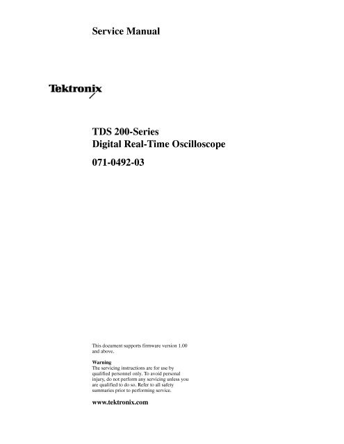
TDS 200-Series Digital Real-Time Oscilloscope Service Manual
TDS 200-Series Digital Real-Time Oscilloscope Service Manual
TDS 200-Series Digital Real-Time Oscilloscope Service Manual

You also want an ePaper? Increase the reach of your titles
YUMPU automatically turns print PDFs into web optimized ePapers that Google loves.
<strong>Service</strong> <strong>Manual</strong><br />
<strong>TDS</strong> <strong>200</strong>-<strong>Series</strong><br />
<strong>Digital</strong> <strong>Real</strong>-<strong>Time</strong> <strong>Oscilloscope</strong><br />
071-0492-03<br />
This document supports firmware version 1.00<br />
and above.<br />
Warning<br />
The servicing instructions are for use by<br />
qualified personnel only. To avoid personal<br />
injury, do not perform any servicing unless you<br />
are qualified to do so. Refer to all safety<br />
summaries prior to performing service.<br />
www.tektronix.com
Copyright © Tektronix, Inc. All rights reserved.<br />
Tektronix products are covered by U.S. and foreign patents, issued and pending. Information in this publication supercedes<br />
that in all previously published material. Specifications and price change privileges reserved.<br />
Tektronix, Inc., P.O. Box 500, Beaverton, OR 97077<br />
TEKTRONIX and TEK are registered trademarks of Tektronix, Inc.
WARRANTY<br />
Tektronix warrants that the products that it manufactures and sells will be free from defects in materials and workmanship for<br />
a period of three (3) years from the date of purchase from an authorized Tektronix distributor. If any such product proves<br />
defective during this warranty period, Tektronix, at its option, either will repair the defective product without charge for parts<br />
and labor, or will provide a replacement in exchange for the defective product. Batteries are excluded from this warranty.<br />
In order to obtain service under this warranty, Customer must notify Tektronix of the defect before the expiration of the<br />
warranty period and make suitable arrangements for the performance of service. Customer shall be responsible for packaging<br />
and shipping the defective product to the service center designated by Tektronix, shipping charges prepaid, and with a copy of<br />
customer proof of purchase. Tektronix shall pay for the return of the product to Customer if the shipment is to a location<br />
within the country in which the Tektronix service center is located. Customer shall be responsible for paying all shipping<br />
charges, duties, taxes, and any other charges for products returned to any other locations.<br />
This warranty shall not apply to any defect, failure or damage caused by improper use or improper or inadequate maintenance<br />
and care. Tektronix shall not be obligated to furnish service under this warranty a) to repair damage resulting from attempts<br />
by personnel other than Tektronix representatives to install, repair or service the product; b) to repair damage resulting from<br />
improper use or connection to incompatible equipment; c) to repair any damage or malfunction caused by the use of<br />
non-Tektronix supplies; or d) to service a product that has been modified or integrated with other products when the effect of<br />
such modification or integration increases the time or difficulty of servicing the product.<br />
THIS WARRANTY IS GIVEN BY TEKTRONIX WITH RESPECT TO THE LISTED PRODUCTS IN LIEU OF<br />
ANY OTHER WARRANTIES, EXPRESS OR IMPLIED. TEKTRONIX AND ITS VENDORS DISCLAIM ANY<br />
IMPLIED WARRANTIES OF MERCHANTABILITY OR FITNESS FOR A PARTICULAR PURPOSE.<br />
TEKTRONIX’ RESPONSIBILITY TO REPAIR OR REPLACE DEFECTIVE PRODUCTS IS THE SOLE AND<br />
EXCLUSIVE REMEDY PROVIDED TO THE CUSTOMER FOR BREACH OF THIS WARRANTY. TEKTRONIX<br />
AND ITS VENDORS WILL NOT BE LIABLE FOR ANY INDIRECT, SPECIAL, INCIDENTAL, OR<br />
CONSEQUENTIAL DAMAGES IRRESPECTIVE OF WHETHER TEKTRONIX OR THE VENDOR HAS<br />
ADVANCE NOTICE OF THE POSSIBILITY OF SUCH DAMAGES.
Table of Contents<br />
Specifications<br />
Operating Information<br />
Theory of Operation<br />
Performance Verification<br />
Adjustment Procedures<br />
General Safety Summary ...................................<br />
<strong>Service</strong> Safety Summary ....................................<br />
Preface ...................................................<br />
Related <strong>Manual</strong>s .................................................<br />
Contacting Tektronix ..............................................<br />
Product End-of-Life Handling ......................................<br />
Specifications ............................................. 1 -1<br />
Operating Information ..................................... 2 -1<br />
General Features ................................................. 2 -2<br />
Installation ...................................................... 2 -3<br />
Extension Modules ............................................... 2 -4<br />
Functional Check ................................................ 2 -5<br />
Probe Compensation .............................................. 2 -6<br />
Self Calibration .................................................. 2 -7<br />
Probe Safety .................................................... 2 -7<br />
Probe Attenuation Setting .......................................... 2 -7<br />
Factory Setup ................................................... 2 -8<br />
Theory of Operation ....................................... 3 -1<br />
Main Board ..................................................... 3 -1<br />
Power Supply ................................................... 3 -2<br />
Display Module .................................................. 3 -2<br />
Front Panel ..................................................... 3 -2<br />
Extension Modules ............................................... 3 -2<br />
Performance Verification ................................... 4 -1<br />
Test Record ..................................................... 4 -2<br />
Performance Verification Procedures ................................. 4 -4<br />
Adjustment Procedures ..................................... 5 -1<br />
Required Equipment .............................................. 5 -1<br />
Adjustment Procedure ............................................. 5 -2<br />
v<br />
vii<br />
ix<br />
ix<br />
x<br />
x<br />
<strong>TDS</strong> <strong>200</strong> <strong>Series</strong> <strong>Digital</strong> <strong>Oscilloscope</strong> <strong>Service</strong> <strong>Manual</strong><br />
i
Table of Contents<br />
Maintenance<br />
Options<br />
Electrical Parts List<br />
Diagrams<br />
Replaceable Parts<br />
Maintenance .............................................. 6 -1<br />
Preparation ..................................................... 6 -1<br />
Preventing ESD .................................................. 6 -1<br />
Inspection and Cleaning ........................................... 6 -2<br />
Removal and Installation Procedures ................................. 6 -5<br />
Troubleshooting ................................................. 6 -38<br />
Repackaging Instructions .......................................... 6 -48<br />
Options .................................................. 7 -1<br />
Electrical Parts List ........................................ 8 -1<br />
Diagrams ................................................. 9 -1<br />
Replaceable Parts .......................................... 10 -1<br />
Parts Ordering Information ......................................... 10 -1<br />
Using the Replaceable Parts List ..................................... 10 -2<br />
ii<br />
<strong>TDS</strong> <strong>200</strong> <strong>Series</strong> <strong>Digital</strong> <strong>Oscilloscope</strong> <strong>Service</strong> <strong>Manual</strong>
Table of Contents<br />
List of Figures<br />
Figure 2 -1: Routing the power cord and security cable .......... 2 -3<br />
Figure 2 -2: Installing an extension module .................... 2 -4<br />
Figure 3 -1: Module-level block diagram (two channel) .......... 3 -3<br />
Figure 3 -2: Module-level block diagram (four channel) .......... 3 -4<br />
Figure 5 -1: <strong>Service</strong> menu enable button ....................... 5 -2<br />
Figure 5 -2: Adjustment setups ............................... 5 -3<br />
Figure 6 -1: Removing the rear feet ........................... 6 -8<br />
Figure 6 -2: Installing the rear feet ............................ 6 -9<br />
Figure 6 -3: Installing a front-case label ....................... 6 -10<br />
Figure 6 -4: Installing a new rear-case label .................... 6 -11<br />
Figure 6 -5: Removing the handle ............................ 6 -12<br />
Figure 6 -6: Installing the handle ............................. 6 -13<br />
Figure 6 -7: Removing and installing the rear cover ............. 6 -15<br />
Figure 6 -8: Removing and installing the front feet .............. 6 -16<br />
Figure 6 -9: Removing and installing the EMI clips .............. 6 -17<br />
Figure 6 -10: Removing the flip stand ......................... 6 -18<br />
Figure 6 -11: Installing the flip stand .......................... 6 -19<br />
Figure 6 -12: Line fuse location .............................. 6 -20<br />
Figure 6 -13: Removing the power supply module ............... 6 -21<br />
Figure 6 -14: Installing the power supply module ............... 6 -22<br />
Figure 6 -15: Removing and installing the internal assembly ...... 6 -24<br />
Figure 6 -16: Installing the copper mesh grounding tube ......... 6 -25<br />
Figure 6 -17: Main board removal ............................ 6 -26<br />
Figure 6 -18: Main board installation ......................... 6 -27<br />
Figure 6 -19: Removing the display module .................... 6 -28<br />
Figure 6 -20: Installing the display module ..................... 6 -30<br />
Figure 6 -21: Removing the front panel module ................. 6 -31<br />
Figure 6 -22: Installing the front panel module ................. 6 -32<br />
Figure 6 -23: Removing and installing the keypad ............... 6 -33<br />
Figure 6 -24: Removing the display shield ...................... 6 -35<br />
Figure 6 -25: Installing the display shield ...................... 6 -36<br />
Figure 6 -26: Measuring the backlight voltage .................. 6 -41<br />
Figure 10 -1: Exploded diagram .............................. 10 -7<br />
<strong>TDS</strong> <strong>200</strong> <strong>Series</strong> <strong>Digital</strong> <strong>Oscilloscope</strong> <strong>Service</strong> <strong>Manual</strong><br />
iii
Table of Contents<br />
List of Tables<br />
Table 1 -1: Specifications ................................... 1 -1<br />
Table 1 -2: General specifications ............................ 1 -5<br />
Table 2 -1: Factory setup settings ............................ 2 -8<br />
Table 5 -1: Required equipment ............................. 5 -1<br />
Table 5 -2: <strong>TDS</strong> 210 and <strong>TDS</strong> 220 Adjustment steps ............. 5 -5<br />
Table 5 -3: <strong>TDS</strong> 224 Adjustment steps ........................ 5 -7<br />
Table 6 -1: Internal inspection check list ...................... 6 -3<br />
Table 6 -2: List of procedures ................................ 6 -7<br />
Table 6 -3: List of error codes ............................... 6 -46<br />
Table 10 -1: Parts list column descriptions ..................... 10 -2<br />
Table 10 -2: Manufacturers cross index ....................... 10 -3<br />
Table 10 -3: Replaceable parts list ............................ 10 -3<br />
Table 10 -4: Replaceable standard accessories .................. 10 -8<br />
Table 10 -5: Replaceable optional accessories .................. 10 -8<br />
iv<br />
<strong>TDS</strong> <strong>200</strong> <strong>Series</strong> <strong>Digital</strong> <strong>Oscilloscope</strong> <strong>Service</strong> <strong>Manual</strong>
General Safety Summary<br />
Review the following safety precautions to avoid injury and prevent damage to<br />
this product or any products connected to it.<br />
Only qualified personnel should perform service procedures.<br />
Injury Precautions<br />
Use Proper Power Cord. To avoid fire hazard, use only the power cord specified<br />
for this product.<br />
Avoid Electric Overload. To avoid electric shock or fire hazard, do not apply a<br />
voltage to a terminal that is outside the range specified for that terminal.<br />
Avoid Overvoltage. To avoid electric shock or fire hazard, do not apply potential<br />
to any terminal, including the common terminal, that varies from ground by more<br />
than the maximum rating for that terminal.<br />
Avoid Electric Shock. To avoid injury or loss of life, do not connect or disconnect<br />
probes or test leads while they are connected to a voltage source.<br />
Ground the Product. This product is grounded through the grounding conductor<br />
of the power cord. To avoid electric shock, the grounding conductor must be<br />
connected to earth ground. Before making connections to the input or output<br />
terminals of the product, ensure that the product is properly grounded.<br />
Connect the Probe Properly. The probe ground lead is at ground potential. Do not<br />
connect the ground lead to an elevated voltage.<br />
Do Not Operate Without Covers. To avoid electric shock or fire hazard, do not<br />
operate this product with covers or panels removed.<br />
Use Proper Fuse. To avoid fire hazard, use only the fuse type and rating specified<br />
for this product.<br />
Do Not Operate in Wet/Damp Conditions. To avoid electric shock, do not operate<br />
this product in wet or damp conditions.<br />
Do Not Operate in an Explosive Atmosphere. To avoid injury or fire hazard, do not<br />
operate this product in an explosive atmosphere.<br />
Product Damage<br />
Precautions<br />
Use Proper Power Source. Do not operate this product from a power source that<br />
applies more than the voltage specified.<br />
Provide Proper Ventilation. To prevent product overheating, provide proper<br />
ventilation.<br />
Do Not Operate With Suspected Failures. If you suspect there is damage to this<br />
product, have it inspected by qualified service personnel.<br />
<strong>TDS</strong> <strong>200</strong> <strong>Series</strong> <strong>Digital</strong> <strong>Oscilloscope</strong> <strong>Service</strong> <strong>Manual</strong><br />
v
General Safety Summary<br />
Symbols and Terms<br />
Terms in this <strong>Manual</strong>. These terms may appear in this manual:<br />
WARNING. Warning statements identify conditions or practices that could result<br />
in injury or loss of life.<br />
CAUTION. Caution statements identify conditions or practices that could result in<br />
damage to this product or other property.<br />
Terms on the Product. These terms may appear on the product:<br />
DANGER indicates an injury hazard immediately accessible as you read the<br />
marking.<br />
WARNING indicates an injury hazard not immediately accessible as you read the<br />
marking.<br />
CAUTION indicates a hazard to property including the product.<br />
Symbols on the Product. The following symbols may appear on the product:<br />
DANGER<br />
High Voltage<br />
Protective Ground<br />
(Earth) Terminal<br />
ATTENTION<br />
Refer to <strong>Manual</strong><br />
Double<br />
Insulated<br />
Certifications and<br />
Compliances<br />
Refer to the specifications section for a listing of certifications and compliances<br />
that apply to this product.<br />
vi<br />
<strong>TDS</strong> <strong>200</strong> <strong>Series</strong> <strong>Digital</strong> <strong>Oscilloscope</strong> <strong>Service</strong> <strong>Manual</strong>
<strong>Service</strong> Safety Summary<br />
Only qualified personnel should perform service procedures. Read this <strong>Service</strong><br />
Safety Summary and the General Safety Summary before performing any service<br />
procedures.<br />
Do Not <strong>Service</strong> Alone. Do not perform internal service or adjustments of this<br />
product unless another person capable of rendering first aid and resuscitation is<br />
present.<br />
Disconnect Power. To avoid electric shock, disconnect the main power by means<br />
of the power cord or, if provided, the power switch.<br />
Use Care When Servicing With Power On. Dangerous voltages or currents may<br />
exist in this product. Disconnect power, remove battery (if applicable), and<br />
disconnect test leads before removing protective panels, soldering, or replacing<br />
components.<br />
To avoid electric shock, do not touch exposed connections.<br />
<strong>TDS</strong> <strong>200</strong> <strong>Series</strong> <strong>Digital</strong> <strong>Oscilloscope</strong> <strong>Service</strong> <strong>Manual</strong><br />
vii
<strong>Service</strong> Safety Summary<br />
viii<br />
<strong>TDS</strong> <strong>200</strong> <strong>Series</strong> <strong>Digital</strong> <strong>Oscilloscope</strong> <strong>Service</strong> <strong>Manual</strong>
Preface<br />
The service manual for the <strong>TDS</strong> <strong>200</strong>-<strong>Series</strong> <strong>Digital</strong> <strong>Real</strong>-<strong>Time</strong> <strong>Oscilloscope</strong><br />
provides information to troubleshoot and repair the instrument to the module<br />
level.<br />
Some <strong>TDS</strong> models have two input channels and an external trigger while other<br />
models have four input channels. Most illustrations in this manual show a two<br />
channel model. Some parts for the four channel model are slightly different<br />
because of the additional channels.<br />
Related <strong>Manual</strong>s<br />
Additional documentation for the instrument is contained in the related manuals<br />
listed below.<br />
Language<br />
User manual<br />
part number<br />
Extension module<br />
instructions part<br />
number<br />
Programmer manual<br />
part number<br />
English 071-0398-XX 071-0409-XX 071-0493-XX<br />
French 071-0400-XX* 071-0483-XX<br />
German 071-0402-XX* 071-0485-XX<br />
Italian 071-0401-XX* 071-0484-XX<br />
Spanish 071-0399-XX* 071-0482-XX<br />
Portuguese 071-0403-XX* 071-0486-XX<br />
Japanese 071-0405-XX* 071-0488-XX<br />
Korean 071-0408-XX* 071-0491-XX<br />
Simplified Chinese 071-0406-XX* 071-0489-XX<br />
Traditional Chinese 071-0407-XX* 071-0490-XX<br />
Russian 071-0404-XX 071-0487-XX<br />
*These manuals contain a language overlay for the front-panel controls.<br />
<strong>TDS</strong> <strong>200</strong> <strong>Series</strong> <strong>Digital</strong> <strong>Oscilloscope</strong> <strong>Service</strong> <strong>Manual</strong><br />
ix
Preface<br />
Contacting Tektronix<br />
Phone 1-800-833-9<strong>200</strong>*<br />
Address<br />
Tektronix, Inc.<br />
Department or name (if known)<br />
14<strong>200</strong> SW Karl Braun Drive<br />
P.O. Box 500<br />
Beaverton, OR 97077<br />
USA<br />
Web site<br />
www.tektronix.com<br />
Sales support 1-800-833-9<strong>200</strong>, select option 1*<br />
<strong>Service</strong> support 1-800-833-9<strong>200</strong>, select option 2*<br />
Technical support<br />
Email: techsupport@tektronix.com<br />
1-800-833-9<strong>200</strong>, select option 3*<br />
1-503-627-2400<br />
6:00 a.m. - 5:00 p.m. Pacific time<br />
* This phone number is toll free in North America. After office hours, please leave a<br />
voice mail message.<br />
Outside North America, contact a Tektronix sales office or distributor; see the<br />
Tektronix web site for a list of offices.<br />
Product End-of-Life Handling<br />
Components that Contain Mercury. The cold cathode fluorescent tube located in<br />
the liquid crystal display backlight contains trace elements of mercury. When you<br />
are ready to reclaim the instrument, you must properly transfer it according to<br />
local regulations concerning mercury-containing equipment or ship the instrument<br />
to the Tektronix Recycling Operations (RAMS). You can contact<br />
Tektronix for the RAMS shipping address and instructions.<br />
x<br />
<strong>TDS</strong> <strong>200</strong> <strong>Series</strong> <strong>Digital</strong> <strong>Oscilloscope</strong> <strong>Service</strong> <strong>Manual</strong>
Specifications<br />
All specifications apply to the <strong>TDS</strong> <strong>200</strong>-<strong>Series</strong> <strong>Digital</strong> <strong>Real</strong>-<strong>Time</strong> <strong>Oscilloscope</strong><br />
with a P2100 probe with the Attenuation switch set to 10X unless noted<br />
otherwise. To meet specifications, two conditions must first be met:<br />
<br />
<br />
The instrument must have been operating continuously for twenty minutes<br />
within the specified operating temperature.<br />
You must perform the Self Cal operation, accessible through the utility menu,<br />
if the operating temperature changes by more than 5° C.<br />
All specifications are guaranteed unless noted “typical.” Specifications that are<br />
marked with the symbol are checked in the chapter Performance Verification.<br />
Table 1 -1: Specifications<br />
Acquisition<br />
Acquisition Modes Sample, Peak detect, and Average<br />
Acquisition Rate, Up to 180 waveforms per second, per channel (Sample acquisition mode, no measurements)<br />
typical<br />
Single Sequence Acquisition Mode Acquisition Stops After<br />
Sample, Peak Detect<br />
Single acquisition, all channels simultaneously<br />
Average<br />
N acquisitions, all channels simultaneously, N is<br />
selectable from 4, 16, 64, and 128<br />
Inputs<br />
Input Coupling<br />
Input Impedance,<br />
DC Coupled, all channela<br />
Input Impedance,<br />
DC Coupled,<br />
EXT TRIG only<br />
P2100 Probe Attenuation<br />
Probe Attenuation Factors<br />
DC, AC, or GND<br />
1MΩ ±2% in parallel with 20 pF ±3pF<br />
<strong>TDS</strong> 210 (B099188 to B119999 & C021679 to C029999)<br />
<strong>TDS</strong> 220 (B065810 to B079999 & C021127 to C029999)<br />
All other <strong>TDS</strong> 210, <strong>TDS</strong> 220, and <strong>TDS</strong> 224<br />
1.2 MΩ ±5% in parallel with 20 pF ±5pF 1MΩ ±5% in parallel with 20 pF ±5pF<br />
1X, 10X<br />
1X, 10X, 100X, 1000X<br />
Maximum Voltage Between Overvoltage Category Maximum Voltage<br />
Signal and Common at<br />
input BNC<br />
CAT I and CAT II<br />
300 V RMS (420 V peak, duty factor < 50%, pulse<br />
width < 100 msec.)<br />
CAT III<br />
150 V RMS<br />
For steady-state sinusoidal waveforms, derate at 20 dB/decade above 100 kHz to 13 V pk at 3 MHz* and<br />
above. Also, refer to Overvoltage Category description on page 1 -7.<br />
* Bandwidth is not valid for the P2100 probe when the switch is set to 1X.<br />
<strong>TDS</strong> <strong>200</strong> <strong>Series</strong> <strong>Digital</strong> <strong>Oscilloscope</strong> <strong>Service</strong> <strong>Manual</strong> 1-1
Specifications<br />
Table 1 -1: Specifications (cont.)<br />
Inputs<br />
Maximum Voltage Between Overvoltage Category Maximum Voltage<br />
Probe Tip and ground<br />
CAT I and CAT II<br />
using P2100 connected to<br />
input BNC<br />
300 V RMS (500 V peak, duty factor < 35%, pulse<br />
width < 100 msec.)<br />
CAT III<br />
100 V RMS<br />
Derate at 20 dB/decade above 900 kHz to 13 V RMS at 27 MHz* and above. Also, refer to Overvoltage<br />
Category description on page 1 -7.<br />
<strong>Time</strong> delay between 150 ps<br />
channels, typical<br />
Channel-to-Channel <strong>TDS</strong> 210 <strong>TDS</strong> 220 and <strong>TDS</strong> 224<br />
Common Mode Rejection,<br />
100:1 at 60 Hz<br />
100:1 at 60 Hz<br />
typical<br />
20:1at30MHz*<br />
20:1at50MHz*<br />
Measured on MATH Ch1 - Ch2 waveform, with test signal applied between signal and common of both<br />
channels, and with the same VOLTS/DIV and coupling settings on each channel. Also measured on MATH<br />
Ch3 - Ch4 waveform for the <strong>TDS</strong> 224.<br />
Channel-to-Channel Cross- <strong>TDS</strong> 210 <strong>TDS</strong> 220 and <strong>TDS</strong> 224<br />
talk<br />
≥100:1 at 30 MHz* ≥100:1 at 50 MHz*<br />
Vertical<br />
Digitizers<br />
VOLTS/DIV Range<br />
Measured on one channel, with 8 division test signal applied between signal and common of the other<br />
channel, the same VOLTS/DIV and coupling settings on each channel, and 50 Ω terminators on each<br />
channel.<br />
8 bit resolution (except when set to 2 mV/div), each channel sampled simultaneously<br />
2 mV/div to 5 V/div at input BNC<br />
(Full bandwidth at >5 mV/div to 5 V/div, 20 MHz at 2 mV/dif to 5 mV/div, except in Peak Detect mode full<br />
bandwidth at >10 mV/div to 5 V/div [20 MHz at 2 mV/div to 10 mV/div])<br />
Position Range 2 mV/div to <strong>200</strong> mV/div, ±2V<br />
> <strong>200</strong> mV/div to 5 V/div, ±50 V<br />
Analog Bandwidth in <strong>TDS</strong> 210 <strong>TDS</strong> 220 and <strong>TDS</strong> 224<br />
Sample and Average modes<br />
at BNC or with P2100 probe,<br />
60 MHz* (when vertical scale set to > 5 mV/div) 100 MHz* (when vertical scale set to > 5 mV/div)<br />
DC Coupled<br />
20 MHz* (when vertical scale set to ≤ 5mV/div)<br />
Analog Bandwidth in Peak <strong>TDS</strong> 210 <strong>TDS</strong> 220 and <strong>TDS</strong> 224<br />
Detect mode (5 s/div to<br />
5 μs/div), typical<br />
50 MHz* (when vertical scale set to > 10 mV/div) 75 MHz* (when vertical scale set to > 10 mV/div)<br />
20 MHz* (when vertical scale set to ≤ 10 mV/div)<br />
Selectable Analog Bandwidth<br />
Limit, typical<br />
Lower Frequency Limit,<br />
AC Coupled<br />
20 MHz*<br />
≤10 Hz at BNC<br />
≤1 Hz when using a 10X passive probe<br />
* Bandwidth is not valid for the P2100 probe when the switch is set to 1X.<br />
1-2 <strong>TDS</strong> <strong>200</strong> <strong>Series</strong> <strong>Digital</strong> <strong>Oscilloscope</strong> <strong>Service</strong> <strong>Manual</strong>
Specifications<br />
Table 1 -1: Specifications (cont.)<br />
Vertical<br />
Rise <strong>Time</strong> at BNC, typical <strong>TDS</strong> 210 <strong>TDS</strong>220 and <strong>TDS</strong> 224<br />
Peak Detect Response<br />
Specifications<br />
Table 1 -1: Specifications (cont.)<br />
Horizontal<br />
Record Length<br />
SEC/DIV Range<br />
Sample Rate and Delay<br />
<strong>Time</strong> Accuracy<br />
2500 samples for each channel<br />
5 ns/div to 5 s/div, in a 1, 2.5, 5 sequence<br />
±100 ppm over any ≥1 ms time interval<br />
Delta <strong>Time</strong> Measurement Conditions Accuracy<br />
Accuracy (Full Bandwidth)<br />
Single-shot, Sample mode ±(1 sample interval + 100 ppm × reading +<br />
0.6 ns)<br />
>16 averages ±(1 sample interval + 100 ppm × reading +<br />
0.4 ns)<br />
Sample interval = s/div ÷ 250<br />
Position Range 5ns/divto10ns/div 25 ns/div to 100 μs/div 250 μs/divto5s/div<br />
Trigger<br />
(-4 div × s/div) to 20 ms (-4 div × s/div) to 50 ms (-4 div × s/div) to 50 s<br />
Trigger Sensitivity, Edge Coupling Sensitivity<br />
Trigger Type<br />
DC CH 1, CH 2,<br />
CH 3 & CH 4<br />
Trigger Sensitivity, Edge<br />
Trigger Type, typical<br />
Coupling<br />
AC<br />
NOISE REJ<br />
HF REJ<br />
LF REJ<br />
<strong>TDS</strong> 210 and <strong>TDS</strong> 220<br />
EXT<br />
EXT/5<br />
Sensitivity<br />
Same as DC at 50 MHz and above<br />
Trigger Level Range Source Range<br />
Internal<br />
±8 divisions from center of screen<br />
Trigger Level Accuracy,<br />
typical<br />
<strong>TDS</strong> 210 and <strong>TDS</strong> 220<br />
EXT<br />
1 div from DC to 10 MHz*,<br />
1.5 div from 10 MHz* to Full<br />
100 mV from DC to 10 MHz*,<br />
150 mV from 10 MHz* to Full<br />
500 mV from DC to 10 MHz*,<br />
750 mV from 10 MHz* to Full<br />
Reduces DC-coupled trigger sensitivity by 2 times for > 10 mV/div to 5 V/div<br />
Same as DC-coupled limit from DC to 7 kHz, attenuates signals above<br />
80 kHz<br />
Same as the DC-coupled limits for frequencies above 300 kHz, attenuates<br />
signals below 300 kHz<br />
±1.6 V<br />
EXT/5 ±8V<br />
Accuracies are for signals having rise and fall times ≥20 ns<br />
Source<br />
Internal<br />
Accuracy<br />
±0.2 div × volts/div within ±4 divisions from center screen<br />
1-4 <strong>TDS</strong> <strong>200</strong> <strong>Series</strong> <strong>Digital</strong> <strong>Oscilloscope</strong> <strong>Service</strong> <strong>Manual</strong>
Specifications<br />
Table 1 -1: Specifications (cont.)<br />
Trigger<br />
<strong>TDS</strong> 210 and <strong>TDS</strong> 220<br />
EXT<br />
EXT/5<br />
±(6% of setting + 40 mV)<br />
±(6% of setting + <strong>200</strong> mV)<br />
* Bandwidth is not valid for the P2100 probe when the switch is set to 1X.<br />
SET LEVEL TO 50%, Operates with input signals ≥50 Hz<br />
typical<br />
Default Settings, Video<br />
Trigger<br />
Sensitivity, Video<br />
Trigger Type, typical<br />
Signal Formats and Field<br />
Rates, Video Trigger Type<br />
Holdoff Range<br />
Measurements<br />
Cursors<br />
Automated Measurements<br />
Trigger mode is Auto and Coupling is AC<br />
Composite video signal<br />
Source<br />
Internal<br />
<strong>TDS</strong> 210 and <strong>TDS</strong> 220<br />
EXT<br />
Range<br />
Pk-pk amplitude of 2 divisions<br />
400 mV<br />
EXT/5<br />
2V<br />
Supports NTSC, PAL, and SECAM broadcast systems for any field or any line<br />
500 ns to 10 s<br />
Voltage difference between cursors (∆V)<br />
<strong>Time</strong> difference between cursors (∆T)<br />
Reciprocal of ∆T in Hertz (1/∆T)<br />
Cycle RMS, Mean, Pk - Pk, Period, Frequency<br />
Table 1 -2: General specifications<br />
Display<br />
Display Type<br />
5.9 in (152 mm) diagonal liquid crystal<br />
Display Resolution 320 horizontal by 240 vertical pixels<br />
Display Contrast Adjustable, temperature compensated<br />
Backlight Intensity, typical 60 cd/m 2<br />
Probe compensator output<br />
Output Voltage, typical 5Vinto≥1MΩ load<br />
Frequency, typical 1 kHz<br />
<strong>TDS</strong> <strong>200</strong> <strong>Series</strong> <strong>Digital</strong> <strong>Oscilloscope</strong> <strong>Service</strong> <strong>Manual</strong> 1-5
Specifications<br />
Table 1 -2: General specifications (cont.)<br />
Power Source<br />
Source Voltage<br />
100 - 120 VAC RMS 10% from 45 Hz through 440 Hz, CAT II<br />
120 - 250 VAC RMS 10% from 45 Hz through 66 Hz, CAT II<br />
Power Consumption <strong>TDS</strong> 210 and <strong>TDS</strong> 220 <strong>TDS</strong> 224<br />
Fuse<br />
Environmental<br />
Less than 20 W<br />
1 A, T rating, 250 V<br />
Less than 25 W<br />
Temperature Operating 0° Cto+50° C<br />
Cooling Method<br />
Nonoperating<br />
Convection<br />
-20° Cto+60° C<br />
Humidity +40° C or below ≤90% relative humidity<br />
+41° Cto+50° C ≤60% relative humidity<br />
Altitude Operating 3,000 m<br />
Nonoperating<br />
15,000 m<br />
Random Vibration Operating 0.31 g RMS from 5 Hz to 500 Hz, 10 minutes on each<br />
axis<br />
Nonoperating<br />
2.46 g RMS from 5 Hz to 500 Hz, 10 minutes on each<br />
axis<br />
Mechanical Shock Operating 50 g, 11 ms, half sine<br />
Mechanical<br />
Size Height 151.4 mm (5.96 in.)<br />
Width<br />
304.8 mm (12 in.)<br />
Depth<br />
120.7 mm (4.75 in.)<br />
Weight (approximate) When packaged for domestic shipment 3.6 kg (8.0 lbs)<br />
1-6 <strong>TDS</strong> <strong>200</strong> <strong>Series</strong> <strong>Digital</strong> <strong>Oscilloscope</strong> <strong>Service</strong> <strong>Manual</strong>
Specifications<br />
Table 1 -2: General specifications (cont.)<br />
Certifications and compliances<br />
EC Declaration of<br />
Conformity<br />
(<strong>TDS</strong> 210, <strong>TDS</strong> 220 &<br />
<strong>TDS</strong> 224)<br />
(<strong>TDS</strong> 210, <strong>TDS</strong> 220,<br />
<strong>TDS</strong> 224, P2100)<br />
(P2100)<br />
Certifications<br />
(<strong>TDS</strong> 210, <strong>TDS</strong> 220,<br />
<strong>TDS</strong> 224)<br />
Meets intent of Directive 89/336/EEC for Electromagnetic Compatibility*; meets the requirements of FCC<br />
Code of Federal Regulations, 47 CFR, Part 15, Subpart B, Class A:<br />
CISPR 11 (Class A): Electromagnetic radiated and conducted emissions<br />
EN 50082-1 European Community Requirements:<br />
IEC 61000-4-2 electrostatic discharge<br />
IEC 61000-4-3 radiated susceptibility**<br />
IEC 61000-4-4 power line fast transients<br />
IEC 61000-4-5 power line surge immunity<br />
IEC 61000-4-6 conducted immunity to RF fields<br />
IEC 61000-4-11 voltage dips, interrupts and variations<br />
AS/NZS 2064, Australian emissions standard for Industrial, Scientific, and Medical Equipment<br />
Low Voltage Directive 73/23/EEC as amended by 93/68/EED:<br />
EN61010-1/A2:1995 Safety requirements for electrical equipment for measurement control, and<br />
laboratory use<br />
EN 61010-2-031:1994<br />
CAN/CSA C22.2 No. 1010.1-92<br />
UL3111-1, First Edition<br />
Particular requirements for hand-held probe assemblies for electrical<br />
measurement and test<br />
(P2100)<br />
IEC61010-1/A2<br />
IEC61010-2-031<br />
CSA Certified Power Cords CSA Certification includes the products and power cords appropriate for use in the North America power<br />
network. All other power cords supplied are approved for the country of use.<br />
Pollution Degree 2 Do not operate in environments where conductive pollutants may be present.<br />
Overvoltage Category Category: Examples of Products in this Category:<br />
CAT III Distribution-level mains, fixed installation<br />
CAT II<br />
CAT I<br />
* Instrument tested with shielded cables.<br />
Local-level mains, appliances, portable equipment<br />
Signal levels in special equipment or parts of equipment, telecommunications,<br />
electronics<br />
** Meets Performance Criterion A with allowed degradation of up to 5 major divisions of trace noise increase from 80 MHz to<br />
<strong>200</strong> MHz and up to 2 divisions of trace noise increase over the range of <strong>200</strong> MHz to 1000 MHz under a 3 V/m RF field. Ambient RF<br />
fields may induce triggering when trigger threshold is offset less than 2.5 major divisions from ground reference.<br />
Adjustment interval<br />
The recommended adjustment interval is one year<br />
<strong>TDS</strong> <strong>200</strong> <strong>Series</strong> <strong>Digital</strong> <strong>Oscilloscope</strong> <strong>Service</strong> <strong>Manual</strong> 1-7
Specifications<br />
1-8 <strong>TDS</strong> <strong>200</strong> <strong>Series</strong> <strong>Digital</strong> <strong>Oscilloscope</strong> <strong>Service</strong> <strong>Manual</strong>
Operating Information<br />
<strong>TDS</strong> <strong>200</strong>-<strong>Series</strong> <strong>Digital</strong> <strong>Oscilloscope</strong>s are two or four channel oscilloscopes in<br />
small, lightweight, benchtop packages that you can use to take ground-referenced<br />
measurements.<br />
In addition to the list of general features, this chapter covers the following topics:<br />
<br />
<br />
<br />
<br />
<br />
<br />
How to install your product<br />
How to add extended functions<br />
How to perform a brief functional check<br />
How to compensate probes<br />
How to use the self calibration routine<br />
How to match your probe attenuation factor<br />
For more detailed information about instrument operation, refer to your user<br />
manual.<br />
<strong>TDS</strong> <strong>200</strong> <strong>Series</strong> <strong>Digital</strong> <strong>Oscilloscope</strong> <strong>Service</strong> <strong>Manual</strong> 2-1
Operating Information<br />
General Features<br />
<br />
<br />
<br />
<br />
<br />
<br />
<br />
<br />
<br />
<br />
<br />
<br />
<br />
<br />
100 MHz (<strong>TDS</strong> 220 and <strong>TDS</strong> 224) or 60 MHz (<strong>TDS</strong> 210) bandwidth with<br />
selectable 20 MHz bandwidth limit<br />
1 GS/s sample rate and 2,500 point record length for each channel<br />
Cursors with readout<br />
Five automated measurements<br />
High-resolution, high-contrast LCD display with temperature compensation<br />
and replaceable backlight<br />
Setup and waveform storage<br />
Autoset for quick setup<br />
Waveform averaging and peak detection<br />
<strong>Digital</strong> real-time oscilloscope (at least ten-times over sampling)<br />
Dual time base<br />
Video trigger capability<br />
RS-232, GPIB, and Centronics communication ports easily added with<br />
optional extension modules<br />
Variable persistence display<br />
User interface available in ten user selectable languages<br />
2-2 <strong>TDS</strong> <strong>200</strong> <strong>Series</strong> <strong>Digital</strong> <strong>Oscilloscope</strong> <strong>Service</strong> <strong>Manual</strong>
Operating Information<br />
Installation<br />
Power Cord<br />
Use only power cords designed for your oscilloscope. Use a power source that<br />
delivers 85 to 275 VAC RMS ,47to63Hz.Refertopage10-9foralistof<br />
available power cords.<br />
Use the power cord notch to help route the cord to the rear of the instrument and<br />
avoid inadvertently disconnecting the power source.<br />
Power cord<br />
notch<br />
Securing cable<br />
Figure 2-1: Routing the power cord and security cable<br />
Security Loop<br />
Use the built-in cable channels to secure both your instrument and extension<br />
module to your location.<br />
<strong>TDS</strong> <strong>200</strong> <strong>Series</strong> <strong>Digital</strong> <strong>Oscilloscope</strong> <strong>Service</strong> <strong>Manual</strong> 2-3
Operating Information<br />
Extension Modules<br />
You can increase the feature set of your oscilloscope by inserting an extension<br />
module. Refer to page 10 -9 for information about the available modules.<br />
Figure 2-2 shows the proper way to install a module without bending the<br />
connecting pins.<br />
CAUTION. Electrostatic discharge (ESD) can damage components in the<br />
extension module and the oscilloscope. Do not operate your instrument with the<br />
extension module connector exposed.<br />
1<br />
2<br />
Figure 2-2: Installing an extension module<br />
2-4 <strong>TDS</strong> <strong>200</strong> <strong>Series</strong> <strong>Digital</strong> <strong>Oscilloscope</strong> <strong>Service</strong> <strong>Manual</strong>
Operating Information<br />
Functional Check<br />
Perform this quick functional check to verify that your instrument is operating<br />
correctly.<br />
ON/OFF<br />
button<br />
1. Turn on the instrument.<br />
Wait until the display shows that all self tests passed. Push the SAVE/RECALL<br />
button, select Setups in the top menu box and push the Recall Factory menu<br />
box. The default Probe menu attenuation setting is 10X.<br />
PASSED<br />
PROBE COMP<br />
2. Set the switch to 10X on the P2100 probe and connect the oscilloscope probe to<br />
channel 1. To do this, align the slot in the probe connector with the key on the<br />
CH 1 BNC, push to connect, and twist to the right to lock the probe in place.<br />
Attach the probe tip and reference lead to the PROBE COMP connectors.<br />
CH 1<br />
3. Push the AUTOSET button. Within a few seconds, you should see a square<br />
wave in the display (approximately 5 V at 1 kHz peak-to-peak).<br />
Push the CH 1 MENU button twice to turn off channel 1, push the CH 2 MENU<br />
button to turn on channel 2, repeat steps 2 and 3. For <strong>TDS</strong> 224, repeat for CH 3<br />
and CH 4.<br />
<strong>TDS</strong> <strong>200</strong> <strong>Series</strong> <strong>Digital</strong> <strong>Oscilloscope</strong> <strong>Service</strong> <strong>Manual</strong> 2-5
Operating Information<br />
Probe Compensation<br />
Perform this adjustment to match your probe to the input channel. This should be<br />
done whenever you attach a probe for the first time to any input channel.<br />
PROBE<br />
COMP<br />
AUTOSE<br />
T button<br />
1. Set the Probe menu attenuation to 10X. Set the switch to 10X on the P2100<br />
probe and connect the oscilloscope probe to channel 1. Attach the probe tip and<br />
reference lead to the PROBE COMP connectors and then press AUTOSET.<br />
If using the probe hook-tip, ensure a proper connection by firmly twisting the<br />
tip onto the probe.<br />
CH 1<br />
2. Check the shape of the displayed waveform.<br />
Overcompensated<br />
Undercompensated<br />
Compensated correctly<br />
3. If necessary, adjust your probe.<br />
Repeat as necessary.<br />
2-6 <strong>TDS</strong> <strong>200</strong> <strong>Series</strong> <strong>Digital</strong> <strong>Oscilloscope</strong> <strong>Service</strong> <strong>Manual</strong>
Operating Information<br />
Self Calibration<br />
The self calibration routine lets you quickly optimize the oscilloscope signal path<br />
for maximum measurement accuracy. You can run the routine at anytime but you<br />
should always run the routine if the ambient temperature changes by 5 Cor<br />
more.<br />
To compensate the signal path, disconnect any probes or cables from the channel<br />
input connectors. Then, press the UTILITY button and select Do Self Cal to<br />
confirm that you are ready to proceed.<br />
Probe Safety<br />
A guard around the probe body provides a finger barrier for protection from<br />
electric shock.<br />
Finger guard<br />
WARNING. To avoid electric shock when using the probe, keep fingers behind the<br />
guard on the probe body.<br />
To avoid electric shock while using the probe, do not touch metallic portions of<br />
the probe head while it is connected to a voltage source.<br />
Connect the probe to the instrument and connect the ground terminal to ground<br />
before you take any measurements.<br />
Probe Attenuation Setting<br />
Probes are available with various attenuation factors which affect the vertical<br />
scale readout of the oscilloscope.<br />
To change (or check) the probe attenuation setting, press the VERTICAL MENU<br />
button (of the channel you’re using) and then press the menu selection next to<br />
Probe until the correct setting is displayed.<br />
This setting remains in effect until changed again.<br />
<strong>TDS</strong> <strong>200</strong> <strong>Series</strong> <strong>Digital</strong> <strong>Oscilloscope</strong> <strong>Service</strong> <strong>Manual</strong> 2-7
Operating Information<br />
NOTE. The default Probe menu attenuation setting is 10X when the oscilloscope<br />
is shipped.<br />
Be sure that the Attenuation switch on the P2100 probe is set to match the Probe<br />
menu selection in the oscilloscope. The probe switch settings are 1X and 10X.<br />
Attenuation switch<br />
NOTE. When the Attenuation switch is set to 1X, the P2100 probe limits the<br />
bandwidth of the oscilloscope to 7 MHz. To use the full bandwidth of the<br />
oscilloscope, be sure to set the switch to 10X.<br />
Factory Setup<br />
The table below lists the state of the instrument after you select Recall Factory<br />
from the SAVE/RECALL menu.<br />
Table 2 -1: Factory setup settings<br />
Control<br />
Acquire mode<br />
Acquire # of averages 16<br />
Channel selection<br />
Cursor H Bar position<br />
Cursor V Bar position<br />
Cursor function<br />
Cursor time units<br />
Delayed time base time/div<br />
Delay time, delayed runs after main<br />
Display format<br />
Display graticule type<br />
Setting<br />
Sample<br />
Channel 1 on<br />
--3.2 divisions from the center<br />
--2 divisions from the center<br />
Off<br />
Seconds<br />
50 μs/div<br />
50 μs<br />
YT<br />
Full<br />
Display contrast 50%<br />
Display style<br />
Display accumulate time<br />
Edge trigger coupling<br />
Vectors<br />
500 ms<br />
DC<br />
2-8 <strong>TDS</strong> <strong>200</strong> <strong>Series</strong> <strong>Digital</strong> <strong>Oscilloscope</strong> <strong>Service</strong> <strong>Manual</strong>
Operating Information<br />
Table 2 -1: Factory setup settings (cont.)<br />
Control<br />
Setting<br />
Edge trigger level<br />
0.0 V<br />
Edge trigger slope<br />
Rising<br />
Edge trigger source Channel 1<br />
Horizontal -- main trigger position 50%<br />
Horizontal -- time base<br />
Main only<br />
Main time base time/div<br />
500 μs/div<br />
Math waveform function<br />
CH1 + CH2<br />
Saved setups<br />
No change<br />
Saved waveforms<br />
No change<br />
Trigger holdoff<br />
Minimum (500 ns)<br />
Trigger mode<br />
Auto<br />
Trigger type<br />
Edge<br />
Vertical bandwidth (all channels)<br />
Full<br />
Vertical coupling (all channels)<br />
DC<br />
Vertical position (all channels)<br />
0div<br />
Vertical volts/div. (all channels)<br />
100 mV/div<br />
<strong>TDS</strong> <strong>200</strong> <strong>Series</strong> <strong>Digital</strong> <strong>Oscilloscope</strong> <strong>Service</strong> <strong>Manual</strong> 2-9
Operating Information<br />
2-10 <strong>TDS</strong> <strong>200</strong> <strong>Series</strong> <strong>Digital</strong> <strong>Oscilloscope</strong> <strong>Service</strong> <strong>Manual</strong>
Theory of Operation<br />
This chapter describes the electrical operation of the <strong>TDS</strong> <strong>200</strong>-<strong>Series</strong> <strong>Digital</strong><br />
<strong>Real</strong>-<strong>Time</strong> <strong>Oscilloscope</strong> to the module level. It describes the basic operation of<br />
each functional circuit block shown in figures 3-1 and 3-2.<br />
Main Board<br />
The Main board contains a two or four channel acquisition system, trigger<br />
system, acquisition/display controller, and system processor. Interfaces are<br />
provided for two signal inputs, external trigger input, probe compensation, front<br />
panel, LCD display, extension module, and power supply. Acquisition and<br />
display functions are implemented in two application specific integrated circuits<br />
(ASICs).<br />
Acquisition System<br />
Signals from the CH 1, CH 2, and EXT TRIG, or CH 1, CH 2, CH 3, and CH 4<br />
input connectors pass through attenuators to the acquisition ASIC. The acquisition<br />
ASIC contains amplifiers and samplers for each input channel, A/D<br />
converter, and trigger logic. The digitized waveform samples are transferred to<br />
the display ASIC. Low voltage regulators supply isolated power to the acquisition<br />
ASIC.<br />
Display System<br />
The display system consists of the display ASIC, DRAM memory, and system<br />
oscillator. Digitized acquisition samples are processed by the display ASIC and<br />
stored into DRAM. The Display ASIC formats the waveform data and generates<br />
drive signals for the LCD display. Front panel scanning is also performed by the<br />
display ASIC.<br />
Processor System<br />
The processor system consists of the microprocessor and memory. The processor<br />
system interprets the front panel controls, programs acquisition and display<br />
parameters, computes waveform measurements, and manages the extension<br />
module interface. Saved setups, waveforms, and calibration constants are stored<br />
in nonvolatile memory. The processor system shares DRAM with the display<br />
system.<br />
Input Signal Interface<br />
BNC connectors are mounted on the main board for the CH 1, CH 2, and trigger<br />
or CH 1, CH 2, CH 3, and CH 4 inputs. The signal inputs are compatible with the<br />
P2100 probes supplied.<br />
Probe Compensation<br />
The PROBE COMP and ground terminals are provided for probe adjustment.<br />
<strong>TDS</strong> <strong>200</strong> <strong>Series</strong> <strong>Digital</strong> <strong>Oscilloscope</strong> <strong>Service</strong> <strong>Manual</strong> 3-1
Theory of Operation<br />
Power Supply<br />
The power supply module generates low voltage DC, a line trigger signal for the<br />
main board, and high voltage AC to power the LCD backlight. The power supply<br />
operates over a wide power line voltage and frequency range.<br />
Display Module<br />
The display module consists of a liquid crystal display (LCD), a display driver,<br />
and a florescent backlight.<br />
Front Panel<br />
The front panel board holds the encoders and push button contacts that the<br />
operator uses to control the instrument. An elastomer mat holds the conductive<br />
pads for the push buttons. Circuits on the front panel convert the matrix into<br />
serial data which is read by the display ASIC on the main Board.<br />
Extension Modules<br />
Each extension module also contains a GPIB, RS -232, and Centronics parallel<br />
printer interface. A ROM on the extension module contains processor instructions<br />
to support the communications interfaces. Extension modules interface with<br />
the processor system through the extension module port connector.<br />
3-2 <strong>TDS</strong> <strong>200</strong> <strong>Series</strong> <strong>Digital</strong> <strong>Oscilloscope</strong> <strong>Service</strong> <strong>Manual</strong>
Theory of Operation<br />
AC Line<br />
3<br />
Power Supply<br />
AC Line In<br />
P3<br />
Backlight Power<br />
GND<br />
DC Out<br />
&Line<br />
Trigger<br />
2<br />
Front Panel<br />
J602<br />
A1 Main<br />
7<br />
GND<br />
5<br />
P53<br />
J603<br />
J131<br />
DC In<br />
P131<br />
J90<br />
1<br />
Display<br />
Backlight<br />
Probe Comp<br />
Signal<br />
J604<br />
LCD<br />
J202<br />
12<br />
J902<br />
Display Control<br />
Probe Comp<br />
GND<br />
J605<br />
J51<br />
CH1<br />
CH2<br />
J52<br />
J601<br />
5<br />
0<br />
J1<br />
Extension<br />
Module<br />
J2<br />
J4<br />
9<br />
24<br />
RS232<br />
GPIB<br />
EXT<br />
TRIG<br />
J53<br />
J3<br />
25<br />
CENTRONICS<br />
Figure 3-1: Module-level block diagram (two channel)<br />
<strong>TDS</strong> <strong>200</strong> <strong>Series</strong> <strong>Digital</strong> <strong>Oscilloscope</strong> <strong>Service</strong> <strong>Manual</strong> 3-3
Theory of Operation<br />
AC Line<br />
3<br />
Power Supply<br />
AC Line In<br />
P3<br />
Backlight Power<br />
GND<br />
DC Out<br />
&Line<br />
Trigger<br />
2<br />
Front Panel<br />
5<br />
J1<br />
J101<br />
J103<br />
A1 Main<br />
GND<br />
J131<br />
DC In<br />
P131<br />
7<br />
J90<br />
1<br />
Display<br />
Backlight<br />
Probe Comp<br />
Signal<br />
J104<br />
LCD<br />
J102<br />
12<br />
J902<br />
Display Control<br />
Probe Comp<br />
GND<br />
J104<br />
CH1<br />
CH2<br />
J<strong>200</strong><br />
J250<br />
J690<br />
5<br />
0<br />
J1<br />
Extension<br />
Module<br />
J2<br />
J4<br />
9<br />
24<br />
RS232<br />
GPIB<br />
CH3<br />
J300<br />
J3<br />
25<br />
CENTRONICS<br />
J350<br />
CH4<br />
Figure 3-2: Module-level block diagram (four channel)<br />
3-4 <strong>TDS</strong> <strong>200</strong> <strong>Series</strong> <strong>Digital</strong> <strong>Oscilloscope</strong> <strong>Service</strong> <strong>Manual</strong>
Performance Verification<br />
This chapter contains performance verification procedures for the specifications<br />
marked with the symbol. The following equipment, or a suitable equivalent, is<br />
required to complete these procedures.<br />
Description<br />
DC Voltage Source<br />
Minimum<br />
requirements<br />
17.5mVto7V,±0.5%<br />
accuracy<br />
Leveled Sine Wave Generator 50 kHz and 100 MHz, ±3%<br />
amplitude accuracy<br />
<strong>Time</strong> Mark Generator<br />
10 ms period, ±25 ppm<br />
accuracy<br />
50 Ω BNC Cable BNCmaletoBNCmale,<br />
≈ 36 in (1 m) long<br />
50 Ω BNC Cable BNCmaletoBNCmale,<br />
≈ 10 in (25 cm) long<br />
50 Ω Feedthrough Termination BNC male and female<br />
connectors<br />
Examples<br />
Wavetek 9100 Universal<br />
Calibration System with<br />
<strong>Oscilloscope</strong> Calibration<br />
Module (Option 250)<br />
Fluke 5500A Multi-product<br />
Calibrator with <strong>Oscilloscope</strong><br />
Calibration Option (Option<br />
5500A-SC)<br />
Tektronix part number<br />
012-0482-00<br />
Tektronix part number<br />
012-0208-00<br />
Tektronix part number<br />
011-0049-01<br />
Dual Banana to BNC Adapter Banana plugs to BNC female Tektronix part number<br />
103-0090-00<br />
BNC T Adapter<br />
BNC male to dual BNC female<br />
connectors<br />
Tektronix part number<br />
103-0030-00<br />
<strong>TDS</strong> <strong>200</strong> <strong>Series</strong> <strong>Digital</strong> <strong>Oscilloscope</strong> <strong>Service</strong> <strong>Manual</strong> 4-1
Performance Verification<br />
Test Record<br />
Serial<br />
number Procedure performed by Date<br />
Test Passed Failed<br />
Self Test<br />
<strong>Oscilloscope</strong> tests Low limit Test result High limit<br />
DC Gain Accuracy, <strong>TDS</strong>210 & <strong>TDS</strong>220<br />
Channel 1 5 mV/div 34.0 mV 36.0 mV<br />
<strong>200</strong> mV/div 1.358 V 1.442 V<br />
2V/div 13.58 V 14.42 V<br />
Channel 2 5 mV/div 34.0 mV 36.0 mV<br />
<strong>200</strong> mV/div 1.358 V 1.442 V<br />
2V/div 13.58 V 14.42 V<br />
DC Gain Accuracy, <strong>TDS</strong>224<br />
Channel 1 5 mV/div 33.6 mV 36.4 mV<br />
<strong>200</strong> mV/div 1.358 V 1.442 V<br />
2V/div 13.58 V 14.42 V<br />
Channel 2 5 mV/div 33.6 mV 36.4 mV<br />
<strong>200</strong> mV/div 1.358 V 1.442 V<br />
2V/div 13.58 V 14.42 V<br />
Channel 3 5 mV/div 33.6 mV 36.4 mV<br />
<strong>200</strong> mV/div 1.358 V 1.442 V<br />
2V/div 13.58 V 14.42 V<br />
Channel 4 5 mV/div 33.6 mV 36.4 mV<br />
<strong>200</strong> mV/div 1.358 V 1.442 V<br />
2V/div 13.58 V 14.42 V<br />
4-2 <strong>TDS</strong> <strong>200</strong> <strong>Series</strong> <strong>Digital</strong> <strong>Oscilloscope</strong> <strong>Service</strong> <strong>Manual</strong>
Performance Verification<br />
<strong>Oscilloscope</strong> tests<br />
Low limit<br />
Test result<br />
High limit<br />
Channel 1 Bandwidth 2.12 V —<br />
Channel 2 Bandwidth 2.12 V —<br />
Channel 3 Bandwidth 1 2.12 V —<br />
Channel 4 Bandwidth 1 2.12 V —<br />
Sample Rate and Delay <strong>Time</strong> Accuracy -2 divs +2 divs<br />
Channel 1 Edge Trigger Sensitivity Stable trigger —<br />
Channel 2 Edge Trigger Sensitivity Stable trigger —<br />
Channel 3 Edge Trigger Sensitivity 1 Stable trigger —<br />
Channel 4 Edge Trigger Sensitivity 1 Stable trigger —<br />
External Edge Trigger Sensitivity 1 Stable trigger —<br />
1 Channels 3 and 4 are only on four channel instruments, and External Edge trigger is only on two channel instruments.<br />
<strong>TDS</strong> <strong>200</strong> <strong>Series</strong> <strong>Digital</strong> <strong>Oscilloscope</strong> <strong>Service</strong> <strong>Manual</strong> 4-3
Performance Verification<br />
Performance Verification Procedures<br />
Before beginning these procedures, two conditions must first be met:<br />
<br />
<br />
The instrument must have been operating continuously for twenty minutes<br />
within the operating temperature range specified.<br />
You must perform the Self Calibration operation described below. If the<br />
ambient temperature changes by more than 5° C, you must perform the Self<br />
Calibration operation again.<br />
The time required to complete the entire procedure is approximately one hour.<br />
WARNING. Some procedures use hazardous voltages. To prevent electrical shock,<br />
always set voltage source outputs to 0 V before making or changing any<br />
interconnections.<br />
Self Test<br />
This internal procedure is automatically performed every time the instrument is<br />
powered on. No test equipment or hookups are required. Verify that no error<br />
messages are displayed before continuing with this procedure.<br />
Self Calibration<br />
The self calibration routine lets you quickly optimize the oscilloscope signal path<br />
for maximum measurement accuracy. You can run the routine at anytime but you<br />
should always run the routine if the ambient temperature changes by 5 Cor<br />
more.<br />
1. Disconnect any probes or cables from the channel 1 and channel 2 input<br />
connectors.<br />
2. Press the UTILITY button and select Do Self Cal to start the routine. The<br />
routine takes approximately one minute to complete.<br />
3. Verify that Self calibration passed.<br />
4-4 <strong>TDS</strong> <strong>200</strong> <strong>Series</strong> <strong>Digital</strong> <strong>Oscilloscope</strong> <strong>Service</strong> <strong>Manual</strong>
Performance Verification<br />
Check DC Gain Accuracy<br />
This test checks the DC gain accuracy of all input channels.<br />
1. Set the DC voltage source output level to 0V.<br />
2. Set up the instrument using the following steps:<br />
Press menu button Select menu item Select setting<br />
SAVE/<br />
Recall<br />
—<br />
RECALL<br />
Factory<br />
CH 1 Probe 1X<br />
ACQUIRE Average 16<br />
MEASURE Source An unchecked channel<br />
Type<br />
Mean<br />
3. As shown below, connect the instrument channel selected in the table to the<br />
DC voltage source.<br />
DC voltage<br />
source<br />
Digitizing oscilloscope<br />
--<br />
+<br />
Dual banana<br />
to BNC<br />
adapter<br />
BNC cable<br />
4. For each VOLTS/DIV setting listed in the table at the top of page 4 -6,<br />
perform the following steps:<br />
a. Set the DC voltage source output level to the positive voltage listed and<br />
then record the mean measurement as V pos .<br />
b. Reverse the polarity of the DC voltage source and then record the mean<br />
measurement as V neg .<br />
c. Calculate V diff =V pos - V neg and then compare V diff to the accuracy<br />
limits in the table.<br />
<strong>TDS</strong> <strong>200</strong> <strong>Series</strong> <strong>Digital</strong> <strong>Oscilloscope</strong> <strong>Service</strong> <strong>Manual</strong> 4-5
Performance Verification<br />
VOLTS/DIV setting DC voltage source output levels Accuracy limits for V diff<br />
<strong>TDS</strong>210 & <strong>TDS</strong>220<br />
5 mV/div +17.5 mV, -17.5 mV 34.0 mV to 36.0 mV<br />
<strong>200</strong> mV/div +700 mV, -700 mV 1.358 V to 1.442 V<br />
2V/div +7.00 V, -7.00 V 13.58 V to 14.42 V<br />
<strong>TDS</strong>224<br />
5 mV/div +17.5 mV, -17.5 mV 33.6 mV to 36.4 mV<br />
<strong>200</strong> mV/div +700 mV, -700 mV 1.358 V to 1.442 V<br />
2V/div +7.00 V, -7.00 V 13.58 V to 14.42 V<br />
5. Set DC voltage source output level to 0V.<br />
6. Disconnect the test setup.<br />
7. Repeat steps 1 through 6 until all input channels have been checked.<br />
Check Bandwidth<br />
This test checks the bandwidth of all input channels.<br />
1. Set up the instrument using the following steps:<br />
Press menu button Select menu item Select setting<br />
SAVE/<br />
RECALL<br />
Recall<br />
Factory<br />
—<br />
CH 1 Probe 1X<br />
ACQUIRE Average 16<br />
TRIGGER Coupling Noise Reject<br />
MEASURE Source An unchecked channel<br />
Type<br />
Pk-Pk<br />
4-6 <strong>TDS</strong> <strong>200</strong> <strong>Series</strong> <strong>Digital</strong> <strong>Oscilloscope</strong> <strong>Service</strong> <strong>Manual</strong>
Performance Verification<br />
2. As shown below, connect the instrument channel selected in the table to the<br />
leveled sine wave generator.<br />
Leveled<br />
sine wave<br />
generator<br />
Digitizing oscilloscope<br />
Output<br />
BNC cable<br />
50 Ω feedthrough<br />
terminator<br />
3. Set the instrument VOLTS/DIV to 500 mV/div.<br />
4. Set the instrument SEC/DIV to 10 μs/div.<br />
5. Set the leveled sine wave generator frequency to 50 kHz.<br />
6. Set the leveled sine wave generator output level so the peak-to-peak<br />
measurement is between 2.98 V and 3.02 V.<br />
7. Set the leveled sine wave generator frequency to 60 MHz if you are checking<br />
a <strong>TDS</strong> 210 or to 100 MHz if you are checking a <strong>TDS</strong> 220 or <strong>TDS</strong> 224.<br />
8. Set the instrument SEC/DIV to 10 ns/div.<br />
9. Check that the peak-to-peak measurement is ≥2.12 V.<br />
10. Disconnect the test setup.<br />
11. Repeat steps 1 through 10 until all input channels have been checked.<br />
Check Sample Rate and<br />
Delay <strong>Time</strong> Accuracy<br />
This test checks the time base accuracy.<br />
1. Set up the instrument using the following steps:<br />
Press menu button Select menu item Select setting<br />
SAVE/<br />
Recall<br />
—<br />
RECALL<br />
Factory<br />
CH 1 Probe 1X<br />
<strong>TDS</strong> <strong>200</strong> <strong>Series</strong> <strong>Digital</strong> <strong>Oscilloscope</strong> <strong>Service</strong> <strong>Manual</strong> 4-7
Performance Verification<br />
2. Connect the instrument to the time mark generator as shown below.<br />
<strong>Time</strong> mark<br />
generator<br />
Digitizing oscilloscope<br />
Output<br />
BNC cable<br />
50 Ω feedthrough<br />
terminator<br />
3. Set the time mark generator period to 10 ms.<br />
4. Set the instrument VOLTS/DIV to 500 mV/div.<br />
5. Set the instrument Main SEC/DIV to 1ms/div.<br />
6. Press SET LEVEL TO 50%.<br />
7. Use the vertical POSITION control to center the test signal on screen.<br />
8. Change the instrument setup using the following steps:<br />
Press menu button Select menu item Select setting<br />
HORIZONTAL Window —<br />
9. Set the instrument Window SEC/DIV to 500 μs/div.<br />
NOTE. Setting the Window SEC/DIV to a setting slower than the Main SEC/DIV<br />
setting resets the main timebase. If this happens, reset the Main SEC/DIV and<br />
then the Window SEC/DIV settings.<br />
10. Use the horizontal POSITION control to set the window position to<br />
10.00 ms.<br />
11. Set the instrument Window SEC/DIV to 500 ns/div.<br />
12. Check that the rising edge of the marker crosses the center horizontal<br />
graticule line within ±2 divisions of center graticule.<br />
4-8 <strong>TDS</strong> <strong>200</strong> <strong>Series</strong> <strong>Digital</strong> <strong>Oscilloscope</strong> <strong>Service</strong> <strong>Manual</strong>
Performance Verification<br />
NOTE. One division of displacement from graticule center corresponds to<br />
a 50 ppm time base error.<br />
13. Disconnect the test setup.<br />
Check Edge Trigger<br />
Sensitivity<br />
This test checks the edge trigger sensitivity for all input channels.<br />
1. Set up the instrument using the following steps:<br />
Press menu button Select menu item Select setting<br />
SAVE/<br />
Recall<br />
—<br />
RECALL<br />
Factory<br />
CH 1 Probe 1X<br />
TRIGGER Mode Normal<br />
ACQUIRE Sample —<br />
MEASURE Source An unchecked channel<br />
Type<br />
Pk-Pk<br />
2. As shown below, connect the instrument channel selected in the table to the<br />
leveled sine wave generator.<br />
Leveled<br />
sine wave<br />
generator<br />
Digitizing oscilloscope<br />
Output<br />
BNC cable<br />
50 Ω feedthrough<br />
terminator<br />
3. Set the leveled sine wave generator frequency to 60 MHz if you are checking<br />
a <strong>TDS</strong> 210 or to 100 MHz if you are checking a <strong>TDS</strong> 220 or <strong>TDS</strong> 224.<br />
4. Set the instrument VOLTS/DIV to 500 mV/div.<br />
5. Set the instrument SEC/DIV to 10 ns/div.<br />
6. Set the leveled sine wave generator output level to approximately 750 mV p-p<br />
so that the measured amplitude is approximately 750 mV. (The measured<br />
amplitude can fluctuate around 750 mV.)<br />
<strong>TDS</strong> <strong>200</strong> <strong>Series</strong> <strong>Digital</strong> <strong>Oscilloscope</strong> <strong>Service</strong> <strong>Manual</strong> 4-9
Performance Verification<br />
7. Press SET LEVEL TO 50%. Adjust TRIGGER LEVEL as necessary and<br />
then check that triggering is stable.<br />
8. Change the instrument setup using the following steps:<br />
Press menu button Select menu item Select setting<br />
TRIGGER Slope Falling<br />
9. Press SET LEVEL TO 50%. Adjust TRIGGER LEVEL as necessary and<br />
then check that triggering is stable.<br />
10. Change the instrument setup using the following steps:<br />
Press menu button Select menu item Select setting<br />
TRIGGER Slope Rising<br />
11. Disconnect the test setup.<br />
12. Repeat steps 1 through 11 until all input channels have been checked.<br />
Check External Edge<br />
Trigger Sensitivity<br />
<strong>TDS</strong> 210 and <strong>TDS</strong> 220 only: this test checks the edge trigger sensitivity for the<br />
external trigger.<br />
1. Set up the instrument using the following steps:<br />
Press menu button Select menu item Select setting<br />
SAVE/<br />
Recall<br />
—<br />
RECALL<br />
Factory<br />
CH 1 Probe 1X<br />
TRIGGER Source Ext<br />
Mode<br />
ACQUIRE Sample —<br />
Normal<br />
MEASURE Source CH1<br />
Type<br />
Pk-Pk<br />
4-10 <strong>TDS</strong> <strong>200</strong> <strong>Series</strong> <strong>Digital</strong> <strong>Oscilloscope</strong> <strong>Service</strong> <strong>Manual</strong>
Performance Verification<br />
2. Connect the instrument to the leveled sine wave generator as shown below.<br />
Leveled<br />
sine wave<br />
generator<br />
Digitizing oscilloscope<br />
Output<br />
50 Ω<br />
feedthrough<br />
terminator<br />
BNC cable<br />
BNC<br />
cable<br />
BNC T connector<br />
3. Set the leveled sine wave generator frequency to 60 MHz if you are checking<br />
a <strong>TDS</strong> 210 or to 100 MHz if you are checking a <strong>TDS</strong> 220.<br />
4. Set the instrument VOLTS/DIV to 500 mV/div.<br />
5. Set the instrument SEC/DIV to 10 ns/div.<br />
6. Set the leveled sine wave generator output level to approximately 750 mV p-p<br />
so that the measured amplitude is approximately 750 mV. (The measured<br />
amplitude can fluctuate around 750 mV.)<br />
7. Press SET LEVEL TO 50%. Adjust TRIGGER LEVEL as necessary and<br />
then check that triggering is stable.<br />
8. Change the instrument setup using the following steps:<br />
Press menu button Select menu item Select setting<br />
TRIGGER Slope Falling<br />
9. Press SET LEVEL TO 50%. Adjust TRIGGER LEVEL as necessary and<br />
then check that triggering is stable.<br />
10. Change the instrument setup using the following steps:<br />
Press menu button Select menu item Select setting<br />
TRIGGER Slope Rising<br />
11. Disconnect the test setup.<br />
<strong>TDS</strong> <strong>200</strong> <strong>Series</strong> <strong>Digital</strong> <strong>Oscilloscope</strong> <strong>Service</strong> <strong>Manual</strong> 4-11
Performance Verification<br />
4-12 <strong>TDS</strong> <strong>200</strong> <strong>Series</strong> <strong>Digital</strong> <strong>Oscilloscope</strong> <strong>Service</strong> <strong>Manual</strong>
Adjustment Procedures<br />
This chapter contains adjustment procedures for the <strong>TDS</strong> <strong>200</strong>-<strong>Series</strong> <strong>Digital</strong><br />
<strong>Real</strong>-<strong>Time</strong> <strong>Oscilloscope</strong>.<br />
Only qualified personnel should perform service procedures. Read the <strong>Service</strong><br />
Safety Summary and the General Safety Summary before performing any service<br />
procedures. Also refer to the chapter Operating Information for information<br />
about using the <strong>TDS</strong> <strong>200</strong>s.<br />
NOTE. The voltage references inside the <strong>TDS</strong> <strong>200</strong>s are very stable over time and<br />
should not require routine updates. Before performing any procedure in this<br />
chapter, first verify that the instrument does not meet specifications. Refer to the<br />
chapter Performance Verification to verify the specifications.<br />
Required Equipment<br />
The following equipment, or a suitable equivalent, is required to complete these<br />
procedures.<br />
Table 5 -1: Required equipment<br />
Description Minimum requirements Examples<br />
DC Voltage Source -20 V to 20 V, ±0.1% accuracy Wavetek 9100 Universal Calibration<br />
System with <strong>Oscilloscope</strong><br />
Calibration Module (Option 250)<br />
Leveled Sinewave<br />
Generator<br />
50 kHz and 100 MHz, ±0.6%<br />
amplitude accuracy<br />
50 Ω BNC Cable BNCmaletoBNCmale,<br />
≈ 36 in (1 m) long<br />
50 Ω BNC Cable (two) BNCmaletoBNCmale,<br />
≈ 10 in (25 cm) long<br />
50 Ω Feedthrough<br />
Termination<br />
Dual Banana to BNC<br />
Adapter<br />
BNC T<br />
BNC male and female<br />
connectors<br />
Fluke 5500A Multi-product<br />
Calibrator with <strong>Oscilloscope</strong><br />
Calibration Option (Option<br />
5500A-SC)<br />
Tektronix part number 012-0482-00<br />
Tektronix part number 012-0208-00<br />
Tektronix part number 011-0049-01<br />
Banana plugs to BNC female Tektronix part number 103-0090-00<br />
One male and two female<br />
BNC connectors<br />
Tektronix part number 103-0030-00<br />
<strong>TDS</strong> <strong>200</strong> <strong>Series</strong> <strong>Digital</strong> <strong>Oscilloscope</strong> <strong>Service</strong> <strong>Manual</strong> 5-1
Adjustment Procedures<br />
Adjustment Procedure<br />
The adjustment procedure consists of 55 steps. Each step requires an external<br />
voltage source for new calibration constants.<br />
Before performing the adjustment procedure, you must warm up the instrument<br />
for at least ten minutes in an ambient temperature between 20° C and 30° C.<br />
Adjustments performed prior to warm-up or outside this temperature range may<br />
result in poor performance.<br />
If all steps in the procedure are completed successfully, a “Pass” message is<br />
displayed and the new calibration constants take affect. If any step fails, the<br />
procedure is aborted and the current calibration is not affected. You can choose to<br />
abort the procedure at any step by selecting FCAL ABORT without affecting the<br />
current calibration.<br />
The equipment setups, shown in Figure 5-2, are required to complete the<br />
adjustment procedure. Tables 5 -2 and 5 -3 list the steps in the procedure and the<br />
signal requirement for each step.<br />
Enable the <strong>Service</strong> Menu<br />
You must enable the service menu to perform the adjustment procedure. With the<br />
instrument on, insert a narrow object such as a plastic alignment tool into the<br />
access hole, shown in Figure 5-1, until you feel the click of the momentary<br />
button. Hold this button in and press the front panel UTILITY button.<br />
Access to<br />
service menu<br />
enable button<br />
Figure 5-1: <strong>Service</strong> menu enable button<br />
A <strong>Service</strong> menu selection replaces the Language menu selection, giving you<br />
access to the service routines.<br />
After adjustment is complete, disable the service menu by again holding in the<br />
internal momentary button and pressing the front panel UTILITY button.<br />
5-2 <strong>TDS</strong> <strong>200</strong> <strong>Series</strong> <strong>Digital</strong> <strong>Oscilloscope</strong> <strong>Service</strong> <strong>Manual</strong>
Adjustment Procedures<br />
DC voltage setup 1<br />
DC voltage<br />
source<br />
Two Channel<br />
Digitizing oscilloscope<br />
Four Channel<br />
Digitizing oscilloscope<br />
--<br />
+<br />
Dual banana to<br />
BNC adapter<br />
BNC cable<br />
BNC cable<br />
10 inch<br />
BNC cables<br />
BNC ‘T’ connector<br />
10 inch<br />
BNC cable<br />
10 inch<br />
BNC cables<br />
BNC ‘T’<br />
connector<br />
s<br />
BNC ‘T’<br />
connector<br />
10 inch BNC cable<br />
10 inch<br />
BNC cables<br />
DC voltage setup 2<br />
DC voltage<br />
source<br />
Digitizing oscilloscope<br />
--<br />
+<br />
Dual banana<br />
to BNC<br />
adapter<br />
BNC cable<br />
Sinewave generator setup<br />
Edge setup<br />
Leveled<br />
sine wave<br />
generator<br />
Digitizing oscilloscope<br />
Square wave<br />
generator<br />
Four Channel<br />
Digitizing oscilloscope<br />
Output<br />
50 Ω feedthrough<br />
terminator<br />
(Table 5 -2 and 5 -3 list<br />
proper channel)<br />
BNC cable<br />
Output<br />
50 Ω feedthrough<br />
terminator<br />
(Table 5 -2 and 5 -3 list<br />
proper channel)<br />
BNC cable<br />
Figure 5-2: Adjustment setups<br />
<strong>TDS</strong> <strong>200</strong> <strong>Series</strong> <strong>Digital</strong> <strong>Oscilloscope</strong> <strong>Service</strong> <strong>Manual</strong> 5-3
Adjustment Procedures<br />
Adjustment Procedure<br />
Use this procedure to load new calibration constants.<br />
1. Turn on the instrument and let it warm up for at least ten minutes.<br />
2. Enable the <strong>Service</strong> menu as described on Page 5 -2.<br />
3. Press the UTILITY button and select <strong>Service</strong> from the menus.<br />
4. Select FCAL INIT to initiate the factory calibration routine. You are now in<br />
step 1 of the procedure.<br />
5. As indicated by Step 1 in Table 5 -2 on page 5 -5 (<strong>TDS</strong> 210 and <strong>TDS</strong> 220)<br />
or Table 5 -3 on page 5 -7 (<strong>TDS</strong> 224), connect a 0.0 VDC source to the<br />
channel inputs.<br />
6. Press FCAL STEP to load the calibration constant for step 1.<br />
7. Follow the screen prompts along with Table 5 -2 on page 5 -5 (<strong>TDS</strong> 210 and<br />
<strong>TDS</strong> 220) or Table 5 -3 on page 5 -7 (<strong>TDS</strong> 224) for the remainder of the<br />
routine, applying the proper signal for each step.<br />
NOTE. During some steps, the instrument may appear to be idle for several<br />
minutes while it is processing information internally. Please have patience.<br />
If any step in the procedure fails, the procedure terminates. Failure will result if<br />
an incorrect signal source is connected. If this happens, you must start the<br />
procedure over from the beginning.<br />
If the procedure completes successfully, a “Pass” message is displayed and the<br />
new adjustment takes effect.<br />
8. Compensate the signal path by performing the self calibration routine.<br />
Disconnect any probes or cables from the channel input connectors. Then,<br />
press the UTILITY button and select Do Self Cal to confirm that you are<br />
ready to proceed.<br />
9. Disable the <strong>Service</strong> menu option.<br />
5-4 <strong>TDS</strong> <strong>200</strong> <strong>Series</strong> <strong>Digital</strong> <strong>Oscilloscope</strong> <strong>Service</strong> <strong>Manual</strong>
Adjustment Procedures<br />
Table 5 -2: <strong>TDS</strong> 210 and <strong>TDS</strong> 220 Adjustment steps<br />
Step:<br />
Firmware<br />
Below V 2.00<br />
Step<br />
Firmware<br />
V2.00andUp Equipment setup Signal source setting Input<br />
1 1 DC Voltage 1 0.0 V CH1 & CH2<br />
2 2 DC Voltage 1 -20.0 V<br />
3 3 DC Voltage 1 -2.0 V<br />
4 4 DC Voltage 1 -1.6 V<br />
5 5 DC Voltage 1 -1.2 V<br />
6 6 DC Voltage 1 -0.8 V<br />
7 7 DC Voltage 1 -0.4 V<br />
8 8 DC Voltage 1 -0.32 V<br />
9 9 DC Voltage 1 -0.2 V<br />
10 10 DC Voltage 1 -0.16 V<br />
11 11 DC Voltage 1 -0.08 V<br />
12 12 DC Voltage 1 -0.04 V<br />
13 13 DC Voltage 1 -0.03 V<br />
14 14 DC Voltage 1 -0.02 V<br />
15 15 DC Voltage 1 -0.015 V<br />
16 16 DC Voltage 1 0.015 V<br />
17 17 DC Voltage 1 0.02 V<br />
18 18 DC Voltage 1 0.03 V<br />
19 19 DC Voltage 1 0.04 V<br />
20 20 DC Voltage 1 0.08 V<br />
21 21 DC Voltage 1 0.16 V<br />
22 22 DC Voltage 1 0.2 V<br />
23 23 DC Voltage 1 0.32 V<br />
24 24 DC Voltage 1 0.4 V<br />
25 25 DC Voltage 1 0.8 V<br />
26 26 DC Voltage 1 1.2 V<br />
27 27 DC Voltage 1 1.6 V<br />
28 28 DC Voltage 1 2.0 V<br />
29 29 DC Voltage 1 20.0 V<br />
30 30 DC Voltage 1 0.0 V<br />
31 31 DC Voltage 2 -5.0 V EXT TRIG<br />
32 32 DC Voltage 2 -1.0 V<br />
33 33 DC Voltage 2 1.0 V<br />
34 34 DC Voltage 2 5.0 V<br />
<strong>TDS</strong> <strong>200</strong> <strong>Series</strong> <strong>Digital</strong> <strong>Oscilloscope</strong> <strong>Service</strong> <strong>Manual</strong> 5-5
Adjustment Procedures<br />
Table 5 -2: <strong>TDS</strong> 210 and <strong>TDS</strong> 220 Adjustment steps (cont.)<br />
Step:<br />
Firmware<br />
Below V 2.00<br />
Step<br />
Firmware<br />
V2.00andUp Equipment setup<br />
Signal source setting<br />
Input<br />
35 35 Sinewave Generator, 50 Ohm 5 kHz, 1 V p-p CH1<br />
36 36 Sinewave Generator, 50 Ohm 1MHz,1V p-p<br />
37 37 Sinewave Generator, 50 Ohm 50 kHz, 1 V p-p<br />
38 38 Sinewave Generator, 50 Ohm 20 MHz, 1 V p-p<br />
39 39 Sinewave Generator, 50 Ohm <strong>TDS</strong> 210: 60 MHz, 1 V p-p<br />
<strong>TDS</strong> 220: 100 MHz, 1 V p-p<br />
40 40 Sinewave Generator, 50 Ohm 5 kHz, 2.5 V p-p<br />
41 41 Sinewave Generator, 50 Ohm 1MHz,2.5V p-p<br />
42 42 Sinewave Generator, 50 Ohm 50 kHz, 2.5 V p-p<br />
43 43 Sinewave Generator, 50 Ohm 20 MHz, 2.5 V p-p<br />
44 44 Sinewave Generator, 50 Ohm <strong>TDS</strong> 210: 60 MHz, 2.5 V p-p<br />
<strong>TDS</strong> 220: 100 MHz, 2.5 V p-p<br />
45 45 Sinewave Generator, 50 Ohm <strong>TDS</strong> 210: 60 MHz, 2.5 V p-p<br />
<strong>TDS</strong> 220: 100 MHz, 2.5 V p-p<br />
None 46 Edge, 50 Ohm 1 kHz, 0 to -800 mV<br />
46 47 Sinewave Generator, 50 Ohm 5 kHz, 1 V p-p CH2<br />
47 48 Sinewave Generator, 50 Ohm 1MHz,1V p-p<br />
48 49 Sinewave Generator, 50 Ohm 50 kHz, 1 V p-p<br />
49 50 Sinewave Generator, 50 Ohm 20 MHz, 1 V p-p<br />
50 51 Sinewave Generator, 50 Ohm <strong>TDS</strong> 210: 60 MHz, 1 V p-p<br />
<strong>TDS</strong> 220: 100 MHz, 1 V p-p<br />
51 52 Sinewave Generator, 50 Ohm 5 kHz, 2.5 V p-p<br />
52 53 Sinewave Generator, 50 Ohm 1MHz,2.5V p-p<br />
53 54 Sinewave Generator, 50 Ohm 50 kHz, 2.5 V p-p<br />
54 55 Sinewave Generator, 50 Ohm 20 MHz, 2.5 V p-p<br />
55 56 Sinewave Generator, 50 Ohm <strong>TDS</strong> 210: 60 MHz, 2.5 V p-p<br />
<strong>TDS</strong> 220: 100 MHz, 2.5 V p-p<br />
5-6 <strong>TDS</strong> <strong>200</strong> <strong>Series</strong> <strong>Digital</strong> <strong>Oscilloscope</strong> <strong>Service</strong> <strong>Manual</strong>
Adjustment Procedures<br />
Table 5 -3: <strong>TDS</strong> 224 Adjustment steps<br />
Step Equipment setup Signal source setting Input<br />
1 DC Voltage 1 0.0 V CH1, CH2, CH3<br />
2 DC Voltage 1 -20.0 V<br />
& CH4<br />
3 DC Voltage 1 -2.0 V<br />
4 DC Voltage 1 -1.6 V<br />
5 DC Voltage 1 -1.2 V<br />
6 DC Voltage 1 -0.8 V<br />
7 DC Voltage 1 -0.4 V<br />
8 DC Voltage 1 -0.32 V<br />
9 DC Voltage 1 -0.2 V<br />
10 DC Voltage 1 -0.16 V<br />
11 DC Voltage 1 -0.08 V<br />
12 DC Voltage 1 -0.04 V<br />
13 DC Voltage 1 -0.03 V<br />
14 DC Voltage 1 -0.02 V<br />
15 DC Voltage 1 -0.015 V<br />
16 DC Voltage 1 0.015 V<br />
17 DC Voltage 1 0.02 V<br />
18 DC Voltage 1 0.03 V<br />
19 DC Voltage 1 0.04 V<br />
20 DC Voltage 1 0.08 V<br />
21 DC Voltage 1 0.16 V<br />
22 DC Voltage 1 0.2 V<br />
23 DC Voltage 1 0.32 V<br />
24 DC Voltage 1 0.4 V<br />
25 DC Voltage 1 0.8 V<br />
26 DC Voltage 1 1.2 V<br />
27 DC Voltage 1 1.6 V<br />
28 DC Voltage 1 2.0 V<br />
29 DC Voltage 1 20.0 V<br />
30 DC Voltage 1 0.0 V<br />
<strong>TDS</strong> <strong>200</strong> <strong>Series</strong> <strong>Digital</strong> <strong>Oscilloscope</strong> <strong>Service</strong> <strong>Manual</strong> 5-7
Adjustment Procedures<br />
Table 5 -3: <strong>TDS</strong> 224 Adjustment steps (cont.)<br />
Step Equipment setup Signal source setting Input<br />
31 Sinewave Generator, 50 Ohm 5 kHz, 1 V p-p CH1<br />
32 Sinewave Generator, 50 Ohm 1MHz,1V p-p<br />
33 Sinewave Generator, 50 Ohm 50 kHz, 1 V p-p<br />
34 Sinewave Generator, 50 Ohm 20 MHz, 1 V p-p<br />
35 Sinewave Generator, 50 Ohm 100 MHz, 1 V p-p<br />
36 Sinewave Generator, 50 Ohm 5 kHz, 2.5 V p-p<br />
37 Sinewave Generator, 50 Ohm 1MHz,2.5V p-p<br />
38 Sinewave Generator, 50 Ohm 50 kHz, 2.5 V p-p<br />
39 Sinewave Generator, 50 Ohm 20 MHz, 2.5 V p-p<br />
40 Sinewave Generator, 50 Ohm 100 MHz, 2.5 V p-p<br />
41 Sinewave Generator, 50 Ohm 77.133 MHz, 1 V p-p<br />
42 Edge, 50 Ohm 1 kHz, 0 to -800 mV<br />
43 Sinewave Generator, 50 Ohm 5 kHz, 1 V p-p CH2<br />
44 Sinewave Generator, 50 Ohm 1MHz,1V p-p<br />
45 Sinewave Generator, 50 Ohm 50 kHz, 1 V p-p<br />
46 Sinewave Generator, 50 Ohm 20 MHz, 1 V p-p<br />
47 Sinewave Generator, 50 Ohm 100 MHz, 1 V p-p<br />
48 Sinewave Generator, 50 Ohm 5 kHz, 2.5 V p-p<br />
49 Sinewave Generator, 50 Ohm 1MHz,2.5V p-p<br />
50 Sinewave Generator, 50 Ohm 50 kHz, 2.5 V p-p<br />
51 Sinewave Generator, 50 Ohm 20 MHz, 2.5 V p-p<br />
52 Sinewave Generator, 50 Ohm 100 MHz, 2.5 V p-p<br />
53 Sinewave Generator, 50 Ohm 5 kHz, 1 V p-p CH3<br />
54 Sinewave Generator, 50 Ohm 1MHz,1V p-p<br />
55 Sinewave Generator, 50 Ohm 50 kHz, 1 V p-p<br />
56 Sinewave Generator, 50 Ohm 20 MHz, 1 V p-p<br />
57 Sinewave Generator, 50 Ohm 100 MHz, 1 V p-p<br />
58 Sinewave Generator, 50 Ohm 5 kHz, 2.5 V p-p<br />
59 Sinewave Generator, 50 Ohm 1MHz,2.5V p-p<br />
60 Sinewave Generator, 50 Ohm 50 kHz, 2.5 V p-p<br />
61 Sinewave Generator, 50 Ohm 20 MHz, 2.5 V p-p<br />
62 Sinewave Generator, 50 Ohm 100 MHz, 2.5 V p-p<br />
63 Sinewave Generator, 50 Ohm 77.133 MHz, 1 V p-p<br />
64 Edge, 50 Ohm 1 kHz, 0 to -800 mV<br />
5-8 <strong>TDS</strong> <strong>200</strong> <strong>Series</strong> <strong>Digital</strong> <strong>Oscilloscope</strong> <strong>Service</strong> <strong>Manual</strong>
Adjustment Procedures<br />
Table 5 -3: <strong>TDS</strong> 224 Adjustment steps (cont.)<br />
Step Equipment setup Signal source setting Input<br />
65 Sinewave Generator, 50 Ohm 5 kHz, 1 V p-p CH4<br />
66 Sinewave Generator, 50 Ohm 1MHz,1V p-p<br />
67 Sinewave Generator, 50 Ohm 50 kHz, 1 V p-p<br />
68 Sinewave Generator, 50 Ohm 20 MHz, 1 V p-p<br />
69 Sinewave Generator, 50 Ohm 100 MHz, 1 V p-p<br />
70 Sinewave Generator, 50 Ohm 5 kHz, 2.5 V p-p<br />
71 Sinewave Generator, 50 Ohm 1MHz,2.5V p-p<br />
72 Sinewave Generator, 50 Ohm 50 kHz, 2.5 V p-p<br />
73 Sinewave Generator, 50 Ohm 20 MHz, 2.5 V p-p<br />
74 Sinewave Generator, 50 Ohm 100 MHz, 2.5 V p-p<br />
<strong>TDS</strong> <strong>200</strong> <strong>Series</strong> <strong>Digital</strong> <strong>Oscilloscope</strong> <strong>Service</strong> <strong>Manual</strong> 5-9
Adjustment Procedures<br />
5-10 <strong>TDS</strong> <strong>200</strong> <strong>Series</strong> <strong>Digital</strong> <strong>Oscilloscope</strong> <strong>Service</strong> <strong>Manual</strong>
Maintenance<br />
This chapter contains the information needed to do periodic and corrective<br />
maintenance on the oscilloscope. The following sections are included:<br />
<br />
<br />
<br />
<br />
<br />
<br />
Preparation refers you to important information contained elsewhere in this<br />
manual.<br />
Preventing ESD provides general information on preventing damage to<br />
internal modules when doing maintenance.<br />
Inspection and Cleaning provides procedures for inspecting the instrument<br />
and cleaning its external and internal modules.<br />
Removal and Installation Procedures provide procedures for the removal and<br />
installation of modules.<br />
Troubleshooting provides information for isolating failed modules.<br />
Repackaging Instructions provides packaging information for shipment or<br />
storage.<br />
Preparation<br />
Only qualified personnel should perform service procedures. Read the <strong>Service</strong><br />
Safety Summary and the General Safety Summary before performing any service<br />
procedures. Also refer to the chapter Operating Information for information<br />
about using the oscilloscope.<br />
Preventing ESD<br />
When performing any service which requires internal access to the instrument,<br />
adhere to the following precautions to avoid damaging internal modules and their<br />
components due to electrostatic discharge (ESD).<br />
CAUTION. Static discharge can damage any semiconductor component in this<br />
instrument.<br />
1. Minimize handling of static-sensitive modules.<br />
2. Transport and store static-sensitive modules in their static protected<br />
containers or on a metal rail. Label any package that contains static-sensitive<br />
modules.<br />
<strong>TDS</strong> <strong>200</strong> <strong>Series</strong> <strong>Digital</strong> <strong>Oscilloscope</strong> <strong>Service</strong> <strong>Manual</strong> 6-1
Maintenance<br />
3. Discharge the static voltage from your body by wearing a grounded antistatic<br />
wrist strap while handling these modules. Do service of static-sensitive<br />
modules only at a static-free work station.<br />
4. Nothing capable of generating or holding a static charge should be allowed<br />
on the work station surface.<br />
5. Handle circuit boards by the edges when possible.<br />
6. Do not slide the modules over any surface.<br />
7. Avoid handling modules in areas that have a floor or work-surface covering<br />
capable of generating a static charge.<br />
Inspection and Cleaning<br />
This section describes how to inspect for dirt and damage, and how to clean the<br />
instrument. Inspection and cleaning are done as preventive maintenance.<br />
Preventive maintenance, when done regularly, may prevent malfunctions and<br />
enhance reliability.<br />
Preventive maintenance consists of visually inspecting and cleaning the<br />
instrument, and using general care when operating it. How often to do maintenance<br />
depends on the severity of the environment in which the instrument is<br />
used. A proper time to perform preventive maintenance is just before adjustment<br />
of the instrument.<br />
General Care<br />
Protect the instrument from adverse weather conditions. The instrument is not<br />
waterproof.<br />
Do not store or leave the instrument where the liquid crystal display (LCD) will<br />
be exposed to direct sunlight for long periods of time.<br />
The front and back cases help keep dust out of the instrument and must be in<br />
place during normal operation.<br />
CAUTION. To avoid damage to the instrument or probes, do not expose it to any<br />
sprays, liquids, or solvents.<br />
6-2 <strong>TDS</strong> <strong>200</strong> <strong>Series</strong> <strong>Digital</strong> <strong>Oscilloscope</strong> <strong>Service</strong> <strong>Manual</strong>
Maintenance<br />
Inspection and Cleaning<br />
Procedures<br />
Inspect and clean the instrument and probes as often as operating conditions<br />
require. The collection of dirt on internal components can cause them to overheat<br />
and breakdown. Dirt also provides an electrical conduction path that could cause<br />
an instrument failure, especially under high-humidity conditions.<br />
Inspection — Exterior. Inspect the outside of the instrument for damage, wear, and<br />
missing parts. Instruments that appear to have been dropped or otherwise abused<br />
should be checked thoroughly to verify correct operation and performance.<br />
Immediately repair defects that could cause personal injury or lead to further<br />
damage to the instrument.<br />
Cleaning Procedure — Exterior. To clean the instrument exterior and probes,<br />
perform the following steps:<br />
1. Remove loose dust on the outside of the instrument and probes with a lint<br />
free cloth. Use care to avoid scratching the clear plastic display shield.<br />
2. Use a soft cloth dampened with water to clean the instrument. You can use a<br />
75% isopropyl alcohol solution for more efficient cleaning.<br />
CAUTION. To avoid damage to the surface of the instrument or probes, do not use<br />
any abrasive or chemical cleaning agents.<br />
Inspection — Interior. During normal use, the instrument case guards the internal<br />
components against common dust and dirt. However, if it appears that the<br />
instrument may have been damaged or has been exposed to an unusually dirty<br />
environment, you should inspect and clean the interior.<br />
To inspect and clean the interior, disassemble the instrument by completing each<br />
of the disassembly procedures in the order given starting on page 6 -12.<br />
Inspect the internal portions of the instrument for damage and wear using<br />
Table 6 -1 as a guide. Defects found should be repaired immediately.<br />
Table 6 -1: Internal inspection check list<br />
Item Inspect for Repair action<br />
Front and Back<br />
Case<br />
Cracks or deformations.<br />
Scratched lettering or display<br />
filter. Loose connectors or<br />
labels.<br />
Repair or replace defective hardware.<br />
Gasket and Foam<br />
Pads<br />
Misplaced or missing pieces.<br />
Relocate or replace defective pieces.<br />
<strong>TDS</strong> <strong>200</strong> <strong>Series</strong> <strong>Digital</strong> <strong>Oscilloscope</strong> <strong>Service</strong> <strong>Manual</strong> 6-3
Maintenance<br />
Table 6 -1: Internal inspection check list (cont.)<br />
Item<br />
Circuit boards<br />
Inspect for<br />
Loose, broken, or corroded<br />
solder connections. Burned<br />
circuit boards. Burned, broken,<br />
or cracked circuit-run plating.<br />
Repair action<br />
Remove failed module and replace with a<br />
new module.<br />
Solder connections Cold solder or rosin joints. Resolder joint and clean with isopropyl<br />
alcohol.<br />
Wiring and cables<br />
Loose plugs or connectors.<br />
Burned, broken, or frayed<br />
wiring.<br />
Firmly seat connectors. Repair or replace<br />
modules with defective wires or cables.<br />
Cleaning Procedure — Interior. To clean the instrument interior, perform the<br />
following steps:<br />
1. Blow off dust with dry, low-pressure, deionized air (approximately 9 psi).<br />
2. Remove any remaining dust with a lint-free cloth dampened in isopropyl<br />
alcohol (75% solution) and rinse with warm deionized water. (A cottontipped<br />
applicator is useful for cleaning in narrow spaces and on circuit<br />
boards.)<br />
STOP. If, after performing steps 1 and 2, a module is clean upon inspection, skip<br />
steps 3 and 4. Proceed with step 5.<br />
If steps 1 and 2 do not remove all the dust or dirt, all modules in the instrument<br />
except the Display Module may be spray washed using a solution of 75%<br />
isopropyl alcohol. Proceed with step 3.<br />
3. Spray wash dirty parts with the 75% isopropyl alcohol solution and wait<br />
60 seconds for the majority of the alcohol to evaporate.<br />
4. Use hot (49 Cto60 C / 120 F to 140 F) deionized water to thoroughly<br />
rinse the parts.<br />
5. Dry all parts with low-pressure, deionized air.<br />
6. Dry all components and assemblies in an oven or drying compartment using<br />
low-temperature (52 Cto66 C / 125 F to 150 F) circulating air.<br />
Lubrication. There is no periodic lubrication required for the oscilloscope.<br />
6-4 <strong>TDS</strong> <strong>200</strong> <strong>Series</strong> <strong>Digital</strong> <strong>Oscilloscope</strong> <strong>Service</strong> <strong>Manual</strong>
Maintenance<br />
Removal and Installation Procedures<br />
This section describes how to remove and install the major mechanical and<br />
electrical modules. It provides the following information:<br />
<br />
<br />
<br />
<br />
Tools Required on page 6 -6 describes the tools needed to perform the<br />
procedures.<br />
List of Modules on page 6 -6 describes where to locate a list of replaceable<br />
modules.<br />
Summary of Procedures on page 6 -7 lists the procedures for removal and<br />
installation of modules.<br />
Rear Feet, on page 6 -8, begins a series of procedures that describe the<br />
removal and installation of modules.<br />
Preparation<br />
Please read the following warning statement. Then read the following general<br />
instructions before removing a module.<br />
WARNING. Only qualified personnel should perform service procedures. Before<br />
doing this or any other procedure in this manual, read the General Safety<br />
Summary and <strong>Service</strong> Safety Summary found at the beginning of this manual.<br />
Always disconnect the power cord before disassembling any portion of the<br />
instrument.<br />
Also, to prevent damage to electrical components, read Preventing ESD on<br />
page 6 -1.<br />
1. Use Figure 10-1 (the exploded view of the instrument) on page 10 -8 to give<br />
you an overview of how the entire instrument is assembled.<br />
2. Read the Summary of Procedures on page 6 -7 to understand which<br />
procedure to use to access a given module. Then read Tools Required on<br />
page 6 -6 for a list of tools needed to remove and install modules in the<br />
oscilloscope.<br />
3. If you are disassembling the oscilloscope for cleaning, refer to the Inspection<br />
and Cleaning procedure on page 6 -3 for cleaning instructions.<br />
<strong>TDS</strong> <strong>200</strong> <strong>Series</strong> <strong>Digital</strong> <strong>Oscilloscope</strong> <strong>Service</strong> <strong>Manual</strong> 6-5
Maintenance<br />
Tools Required<br />
You will need the following tools to remove and replace all the modules in the<br />
oscilloscope.<br />
Tools<br />
Torque-limiting screwdriver, 12 in lb (1.3 N ⋅ m) range with Torx® T-15 tip<br />
Screwdriver with inch flat blade<br />
Pliers<br />
Sharp knife (X-ACTO® knife or equivalent)<br />
List of Modules<br />
The Mechanical Parts List chapter provides a list of all replaceable modules.<br />
Any electrical or mechanical module, assembly, or part listed in the parts list is<br />
referred to as a module.<br />
6-6 <strong>TDS</strong> <strong>200</strong> <strong>Series</strong> <strong>Digital</strong> <strong>Oscilloscope</strong> <strong>Service</strong> <strong>Manual</strong>
Maintenance<br />
Summary of Procedures<br />
Table 6 -2 lists all procedures in order of increasing complexity. Complete<br />
disassembly is best achieved by following the procedures in the order given.<br />
Table 6 -2: List of procedures<br />
Procedure<br />
Begins on Page<br />
Rear Feet 6-8<br />
Front-Case Label 6-10<br />
Rear-Case Label 6-11<br />
Handle 6-12<br />
Power Button 6-13<br />
Rear Case 6-14<br />
Front Feet 6-16<br />
EMI Clips 6-17<br />
Flip Stand 6-18<br />
PowerLineFuse 6-20<br />
Power Supply Module 6-21<br />
Front Panel Knobs 6-23<br />
Internal Assembly 6-24<br />
Main Board Module 6-26<br />
Display Module 6-28<br />
Front Panel Module 6-30<br />
Keypad 6-33<br />
Display Shield 6-35<br />
Front Case 6-37<br />
<strong>TDS</strong> <strong>200</strong> <strong>Series</strong> <strong>Digital</strong> <strong>Oscilloscope</strong> <strong>Service</strong> <strong>Manual</strong> 6-7
Maintenance<br />
Rear Feet<br />
No tools are required to remove the feet.<br />
Removal. Use this procedure to remove the rear feet.<br />
1. Place the instrument face down on a soft surface (such as an anti-static mat).<br />
2. Slide the feet up and out of the rear case as shown in Figure 6-1.<br />
NOTE. You may want to use a flat blade screwdriver to pry up on the foot. Use<br />
care not to mar the surface of the rear case.<br />
Rear foot (2)<br />
Figure 6-1: Removing the rear feet<br />
6-8 <strong>TDS</strong> <strong>200</strong> <strong>Series</strong> <strong>Digital</strong> <strong>Oscilloscope</strong> <strong>Service</strong> <strong>Manual</strong>
Maintenance<br />
Installation. Use this procedure to install the feet.<br />
1. Place the rear case face down on a soft surface (such as an anti-static mat).<br />
2. Align the slots of the rear foot with the guides in the rear case as shown in<br />
Figure 6-2 and press the foot in.<br />
Rear foot<br />
(2)<br />
Figure 6-2: Installing the rear feet<br />
<strong>TDS</strong> <strong>200</strong> <strong>Series</strong> <strong>Digital</strong> <strong>Oscilloscope</strong> <strong>Service</strong> <strong>Manual</strong> 6-9
Maintenance<br />
Front-Case Label<br />
You will need a sharp knife and needle-nose pliers to remove the front-case label.<br />
CAUTION. Removal of a front-case label will destroy it. Do not remove it unless it<br />
needs to be replaced.<br />
Removal. Use the sharp knife to pry up a corner of the label and use the pliers to<br />
peel the label off.<br />
Installation. Use this procedure to install a new front-panel label in either a new<br />
or the existing front case.<br />
1. Peel the paper off the back side of the new label.<br />
2. Handling the label by its edges only, align it with the recess in the front case<br />
as shown in Figure 6-3.<br />
3. When properly aligned, press the new label into place.<br />
Figure 6-3: Installing a front-case label<br />
6-10 <strong>TDS</strong> <strong>200</strong> <strong>Series</strong> <strong>Digital</strong> <strong>Oscilloscope</strong> <strong>Service</strong> <strong>Manual</strong>
Maintenance<br />
Rear-Case Label<br />
You will need a sharp knife and needle-nose pliers to remove the rear-case label.<br />
CAUTION. Removal of a rear-case label will destroy it. Do not remove it unless it<br />
needs to be replaced.<br />
Removal. Use the sharp knife to pry up a corner of the label and use the pliers to<br />
peel the label off.<br />
Installation. Use this procedure to install a new rear-case label in either a new or<br />
the existing rear case.<br />
1. Peel the paper off the back side of the new label.<br />
2. Handling the label by its edges only, align it with the recess in the rear case<br />
as shown in Figure 6-4.<br />
3. When properly aligned, press the new label into place.<br />
Rear label<br />
Figure 6-4: Installing a new rear-case label<br />
<strong>TDS</strong> <strong>200</strong> <strong>Series</strong> <strong>Digital</strong> <strong>Oscilloscope</strong> <strong>Service</strong> <strong>Manual</strong> 6-11
Maintenance<br />
Handle<br />
You will need a flat-blade screw driver to remove the handle.<br />
Removal. Use this procedure to remove the handle.<br />
1. Place the instrument on its feet.<br />
2. With the handle laying down, pry one end of the handle out of the case as<br />
shown in Figure 6-5.<br />
NOTE. Use care not to mar the surface with the screwdriver.<br />
3. Slide the handle towards the back of the rear case.<br />
Figure 6-5: Removing the handle<br />
6-12 <strong>TDS</strong> <strong>200</strong> <strong>Series</strong> <strong>Digital</strong> <strong>Oscilloscope</strong> <strong>Service</strong> <strong>Manual</strong>
Maintenance<br />
Installation. Use this procedure to install the handle.<br />
1. Place the instrument on its feet.<br />
2. From behind the rear case with the handle laying down, slide the handle<br />
along the groves in the case until the handle snaps into place as shown in<br />
Figure 6-6.<br />
Figure 6-6: Installing the handle<br />
Power Button<br />
Remove the power button by firmly grasping the button (with pliers if necessary)<br />
and pull it straight out of the cabinet. Reinstall the button by pressing it onto the<br />
power button shaft until it snaps into place.<br />
NOTE. Wrap the plier jaws with tape (such as electrical) to avoid marring the<br />
button surface.<br />
<strong>TDS</strong> <strong>200</strong> <strong>Series</strong> <strong>Digital</strong> <strong>Oscilloscope</strong> <strong>Service</strong> <strong>Manual</strong> 6-13
Maintenance<br />
Rear Case<br />
You will need a torque-limiting Torx® T-15 screwdriver and a flat-blade<br />
screwdriver for this procedure.<br />
Removal. First remove the handle and power button using the procedures on<br />
pages 6 -12 and 6 -13, then use this procedure to remove the rear case.<br />
1. If installed, remove the extension module from the rear of the instrument.<br />
CAUTION. Do not remove the rear case with an extension module installed.<br />
2. Place the instrument face down on a soft surface (such as an anti-static mat).<br />
3. Remove the two screws located in the handle recesses. Refer to Figure 6-7.<br />
4. Slip the flat-blade screwdriver between the rear case and front case at the<br />
bottom of the instrument to disengage the tabs and lift the rear case off.<br />
Installation. Use this procedure to install the rear case.<br />
1. Place the instrument face down on a soft surface (such as an anti-static mat).<br />
2. Slide the rear case over the assembly until the bottom tabs of the front case<br />
lock into the rear case.<br />
CAUTION. Be careful to align the guide ribs and to not pinch any wires or other<br />
parts between the front and rear cases. If used, make sure that the copper mesh<br />
grounding tube is in the proper place as shown in Figure 6-7.<br />
3. Install the two screws located in the handle recesses.<br />
CAUTION. Avoid cross threading the screws that secure the rear case to the front<br />
case. An easy way to avoid this is to slip the screw into the hole and, using slight<br />
pressure, slowly rotate the screw counterclockwise until you feel the screw slip<br />
into the screw threads. Then tighten the screw clockwise. A properly started<br />
screw will have very little resistance going in.<br />
4. Install the handle and the power button.<br />
6-14 <strong>TDS</strong> <strong>200</strong> <strong>Series</strong> <strong>Digital</strong> <strong>Oscilloscope</strong> <strong>Service</strong> <strong>Manual</strong>
Maintenance<br />
Retaining screw<br />
Rear case<br />
Retaining screw<br />
Retaining tab (7)<br />
Copper mesh tubing<br />
Front case<br />
Figure 6-7: Removing and installing the rear cover<br />
<strong>TDS</strong> <strong>200</strong> <strong>Series</strong> <strong>Digital</strong> <strong>Oscilloscope</strong> <strong>Service</strong> <strong>Manual</strong> 6-15
Maintenance<br />
Front Feet<br />
You will need a torque-limiting Torx® T-15 screwdriver and a flat-blade<br />
screwdriver for this procedure.<br />
Removal. First remove the handle, power button, and rear case using the<br />
procedures on pages 6 -12, 6 -13, and 6 -14. Then, slide the front feet out of the<br />
front case as shown in Figure 6-8.<br />
Installation. Slide the feet into the slots provided in the front case as shown in<br />
Figure 6-8. Use the installation procedures for each module removed to<br />
reassemble the instrument.<br />
Front foot (2)<br />
Front case<br />
Figure 6-8: Removing and installing the front feet<br />
6-16 <strong>TDS</strong> <strong>200</strong> <strong>Series</strong> <strong>Digital</strong> <strong>Oscilloscope</strong> <strong>Service</strong> <strong>Manual</strong>
Maintenance<br />
EMI Clips<br />
You will need a torque-limiting Torx® T-15 screwdriver and a flat-blade<br />
screwdriver for this procedure.<br />
Removal. First remove the handle, power button, and rear case using the<br />
procedures on pages 6 -12, 6 -13, and 6 -14. Then, slide the four EMI clips out of<br />
the rear case as shown in Figure 6-9.<br />
NOTE. The EMI clips can be pushed out from the rear of the case using a narrow<br />
flat-blade screwdriver.<br />
Installation. Slide the four EMI clips into the slots provided in the rear case as<br />
shown in Figure 6-9. Use the installation procedures for each module removed to<br />
reassemble the instrument.<br />
Figure 6-9: Removing and installing the EMI clips<br />
<strong>TDS</strong> <strong>200</strong> <strong>Series</strong> <strong>Digital</strong> <strong>Oscilloscope</strong> <strong>Service</strong> <strong>Manual</strong> 6-17
Maintenance<br />
Flip Stand<br />
You will need a torque-limiting Torx® T-15 screwdriver and a flat-blade<br />
screwdriver for this procedure.<br />
Removal. First remove the handle, power button, and rear case using the<br />
procedures on pages 6 -12, 6 -13, and 6 -14. Then, use the following procedure to<br />
remove the flip stand.<br />
1. Place the rear case face down on a soft surface (such as an anti-static mat).<br />
2. With the stand folded against the rear case (in the up position), push the stand<br />
out of the rear case channels as shown in Figure 6-10.<br />
Rear case<br />
Flip stand<br />
Figure 6-10: Removing the flip stand<br />
6-18 <strong>TDS</strong> <strong>200</strong> <strong>Series</strong> <strong>Digital</strong> <strong>Oscilloscope</strong> <strong>Service</strong> <strong>Manual</strong>
Maintenance<br />
Installation. Use this procedure to install the flip stand.<br />
1. Orient the flip stand to the rear case, aligning the flip stand slots to the rear<br />
case tabs as shown in Figure 6-11.<br />
2. With the stand in the folded up position, snap the stand into place.<br />
3. Use the installation procedures for each module removed to reassemble the<br />
instrument.<br />
Rear case<br />
Flip stand<br />
Figure 6-11: Installing the flip stand<br />
<strong>TDS</strong> <strong>200</strong> <strong>Series</strong> <strong>Digital</strong> <strong>Oscilloscope</strong> <strong>Service</strong> <strong>Manual</strong> 6-19
Maintenance<br />
Power Line Fuse<br />
You will need a torque-limiting Torx® T-15 screwdriver and a flat-blade<br />
screwdriver for this procedure.<br />
First remove the handle, power button, and rear case using the procedures on<br />
pages 6 -12, 6 -13, and 6 -14 to access the line fuse.<br />
The line fuse is located on the power supply module as shown in Figure 6-12. If<br />
the fuse tests bad, replace it with a fuse of the same type and rating.<br />
Use the installation procedures for each module removed to reassemble the<br />
instrument.<br />
Line fuse<br />
Power supply module<br />
Front case<br />
Figure 6-12: Line fuse location<br />
6-20 <strong>TDS</strong> <strong>200</strong> <strong>Series</strong> <strong>Digital</strong> <strong>Oscilloscope</strong> <strong>Service</strong> <strong>Manual</strong>
Maintenance<br />
Power Supply Module<br />
You will need a torque-limiting Torx® T-15 screwdriver and a flat-blade<br />
screwdriver for this procedure.<br />
Removal. First remove the handle, power button, and rear case using the<br />
procedures on pages 6 -12, 6 -13, and 6 -14. Then, use the following procedure to<br />
remove the power supply module. Refer to Figure 6-13.<br />
1. Disconnect the following wires.<br />
a. The line cord ground wire on the main board at J602 or J101.<br />
b. The seven-conductor ribbon cable on the main board at J131.<br />
c. The two-conductor backlight cable on the power supply module.<br />
2. Slightly bend back the two securing tabs at the bottom of the power supply<br />
module and lift the module out of the inner chassis.<br />
Seven-conductor<br />
ribbon cable<br />
Two-conductor<br />
backlight cable<br />
Power supply module<br />
Front case<br />
Line cord<br />
ground wire<br />
Figure 6-13: Removing the power supply module<br />
<strong>TDS</strong> <strong>200</strong> <strong>Series</strong> <strong>Digital</strong> <strong>Oscilloscope</strong> <strong>Service</strong> <strong>Manual</strong> 6-21
Maintenance<br />
Installation. Use this procedure to install the power supply module. Refer to<br />
Figure 6-14.<br />
1. Place the power supply module into the inner chassis, placing the board<br />
under the three tabs at the top of the inner chassis.<br />
2. Snap the bottom of the module into place.<br />
3. Reconnect the following wires.<br />
a. The line cord ground wire on the main board at J602 or J101.<br />
b. The seven-conductor ribbon cable on the main board at J131.<br />
c. The two-conductor backlight cable on the power supply module.<br />
4. Use the installation procedures for each module removed to reassemble the<br />
instrument.<br />
Seven-conductor<br />
ribbon cable<br />
Two-conductor<br />
backlight cable<br />
Power supply module<br />
Front case<br />
Line cord<br />
ground wire<br />
Figure 6-14: Installing the power supply module<br />
6-22 <strong>TDS</strong> <strong>200</strong> <strong>Series</strong> <strong>Digital</strong> <strong>Oscilloscope</strong> <strong>Service</strong> <strong>Manual</strong>
Maintenance<br />
Front-Panel Knobs<br />
Remove the front panel knobs by firmly grasping the knob (with pliers if<br />
necessary) and pull it away from the front panel. Install front panel knobs by<br />
aligning the keyed knob with the shaft and pressing the knob onto the shaft.<br />
NOTE. Wrap the plier jaws with tape (such as electrical) to avoid marring the<br />
knob surface.<br />
<strong>TDS</strong> <strong>200</strong> <strong>Series</strong> <strong>Digital</strong> <strong>Oscilloscope</strong> <strong>Service</strong> <strong>Manual</strong> 6-23
Maintenance<br />
Internal Assembly<br />
You will need a torque-limiting Torx® T-15 screwdriver and a flat-blade<br />
screwdriver for this procedure.<br />
Removal. First remove the handle, power button, and rear case using the<br />
procedures on pages 6 -12, 6 -13, and 6 -14. Then, use the following procedure to<br />
remove the internal assembly.<br />
1. Remove all the front panel knobs.<br />
2. Lift the entire internal assembly (housing all of the boards and the display<br />
screen) out of the front case as shown in Figure 6-15.<br />
NOTE. The switch keypad will most likely remain inside the front case. It does not<br />
need to be removed with the internal assembly.<br />
Internal assembly<br />
Keypad<br />
Conductive foam pad<br />
Front case<br />
Figure 6-15: Removing and installing the internal assembly<br />
6-24 <strong>TDS</strong> <strong>200</strong> <strong>Series</strong> <strong>Digital</strong> <strong>Oscilloscope</strong> <strong>Service</strong> <strong>Manual</strong>
Maintenance<br />
Installation. Use this procedure to install the internal assembly.<br />
1. Place the internal assembly into the front case as shown in Figure 6-15.<br />
2. If used, place the copper mesh grounding tube between the main board<br />
module shield and the front case as shown in Figure 6-16. This part is not<br />
used on later instruments; check the Mechanical Parts List for your serial<br />
number (see page 10 -8).<br />
3. Use the installation procedures for each module removed to reassemble the<br />
instrument.<br />
Front case<br />
Copper<br />
mesh tubing<br />
Figure 6-16: Installing the copper mesh grounding tube<br />
<strong>TDS</strong> <strong>200</strong> <strong>Series</strong> <strong>Digital</strong> <strong>Oscilloscope</strong> <strong>Service</strong> <strong>Manual</strong> 6-25
Maintenance<br />
Main Board Module<br />
You will need a torque-limiting Torx® T-15 screwdriver and a flat-blade<br />
screwdriver for this procedure.<br />
Removal. First remove the handle, power button, and rear case using the<br />
procedures on pages 6 -12, 6 -13, and 6 -14. Then, use the following procedure to<br />
remove the main board module.<br />
1. Remove the entire internal assembly from the front case using the procedure<br />
on page 6 -24.<br />
2. Disconnect the following wires on the main board. Refer to Figure 6-17.<br />
a. The line cord ground wire at J602 or J101 and the seven-conductor<br />
ribbon cable at J131 from the power supply module.<br />
b. The ribbon cable at J603 or J103 from the front panel module.<br />
c. The ribbon cable at J202 or J102 from the display module.<br />
3. From the bottom of the internal chassis, slightly bend the two securing tabs<br />
and tilt the board down until it clears the tabs. Refer to Figure 6-17.<br />
4. Pull the board out of the front slots of the internal chassis (near the BNC<br />
connectors).<br />
6-26 <strong>TDS</strong> <strong>200</strong> <strong>Series</strong> <strong>Digital</strong> <strong>Oscilloscope</strong> <strong>Service</strong> <strong>Manual</strong>
Maintenance<br />
Line cord ground wire<br />
Display<br />
module ribbon<br />
cable<br />
Internal chassis<br />
Power supply<br />
ribbon cable<br />
Front panel cable<br />
Main<br />
board<br />
Figure 6-17: Main board removal<br />
Installation. Use this procedure to install the main board module. Refer to<br />
Figure 6-18.<br />
1. Working from the bottom of the internal chassis, place the front of the main<br />
board module into the slots on the internal chassis (near the BNC connectors).<br />
2. Keeping the module in place, press the board into place so that the securing<br />
tabs lock onto the bottom of the board. Note that there are two board guides<br />
on the chassis that must match the cutouts on the main board.<br />
3. Reconnect the following wires on the main board. Refer to Figure 6-17.<br />
a. The line cord ground wire at J602 or J101 and the seven-conductor<br />
ribbon cable at J131 from the power supply module.<br />
b. The ribbon cable at J603 or J103 from the front panel module.<br />
c. The ribbon cable at J202 or J102 from the display module.<br />
4. Place the entire internal assembly (housing all of the boards and the display<br />
screen) into the front case as shown in Figure 6-16.<br />
<strong>TDS</strong> <strong>200</strong> <strong>Series</strong> <strong>Digital</strong> <strong>Oscilloscope</strong> <strong>Service</strong> <strong>Manual</strong> 6-27
Maintenance<br />
5. Use the installation procedures for each module removed to reassemble the<br />
instrument.<br />
Line cord ground wire<br />
Internal chassis<br />
Power supply<br />
ribbon cable<br />
Display<br />
module ribbon<br />
cable<br />
Front panel cable<br />
Board guides<br />
Cutout<br />
Main<br />
board<br />
Figure 6-18: Main board installation<br />
Display Module<br />
You will need a torque-limiting Torx® T-15 screwdriver and a flat-blade<br />
screwdriver for this procedure.<br />
Removal. First remove the handle, power button, and rear case using the<br />
procedures on pages 6 -12, 6 -13, and 6 -14. Then, use the following procedure to<br />
remove the display module.<br />
1. Remove the entire internal assembly from the front case using the procedure<br />
on page 6 -24.<br />
2. Disconnect the display module ribbon cable at J202 or J102 on the main<br />
board by pulling straight up from the connector. Refer to Figure 6-17.<br />
3. Disconnect the backlight cable from the power supply module. Refer to<br />
Figure 6-14.<br />
4. Slightly bend the two securing tabs on the left side of the display module and<br />
lift the left side up until it clears the tabs. Then slide the display to the left<br />
until the right-side tabs are disengaged. Refer to Figure 6-19.<br />
6-28 <strong>TDS</strong> <strong>200</strong> <strong>Series</strong> <strong>Digital</strong> <strong>Oscilloscope</strong> <strong>Service</strong> <strong>Manual</strong>
Maintenance<br />
CAUTION. The display shield is attached to the display module. Removing the<br />
shield will destroy the attaching gasket.<br />
Backlight<br />
cable<br />
Internal chassis<br />
Display module<br />
Ribbon cable<br />
Figure 6-19: Removing the display module<br />
Installation. Use this procedure to install the display module.<br />
1. Route the display ribbon cable through the opening in the internal chassis as<br />
shown in Figure 6-20. If installing a new module, fold the ribbon cable as<br />
shown.<br />
2. Place the tabs on the right side of the display module into the slots of the<br />
internal chassis located under the front panel board. It is not necessary to<br />
remove the front panel board. Refer to Figure 6-20.<br />
3. Route the backlight cable through the opening in the internal chassis as<br />
shown in Figure 6-20.<br />
4. Lower the left side of the display module into the internal chassis until the<br />
two securing tabs lock on to the display module. Note that the backlight<br />
cable protruding from each end of the module must align with the cutouts of<br />
the inner chassis. Refer to Figure 6-20.<br />
5. Reconnect the display module ribbon cable at J202 or J102 on the main<br />
board by pushing the cable straight down into the connector. Refer to Figure<br />
6-17.<br />
<strong>TDS</strong> <strong>200</strong> <strong>Series</strong> <strong>Digital</strong> <strong>Oscilloscope</strong> <strong>Service</strong> <strong>Manual</strong> 6-29
Maintenance<br />
6. Reconnect the backlight cable to the power supply module. Refer to<br />
Figure 6-14.<br />
7. Place the entire internal assembly into the front cover. Refer to Figure 6-16.<br />
8. Use the installation procedures for each module removed to reassemble the<br />
instrument.<br />
Backlight cable to<br />
power supply<br />
module<br />
Internal chassis<br />
Display module<br />
Left side view of<br />
internal chassis<br />
Do not pinch backlight cable<br />
when installing the display module.<br />
Ribbon cable to<br />
main board<br />
Figure 6-20: Installing the display module<br />
Front Panel Module<br />
You will need a torque-limiting Torx® T-15 screwdriver and a flat-blade<br />
screwdriver for this procedure.<br />
Removal. First remove the handle, power button, and rear case using the<br />
procedures on pages 6 -12, 6 -13, and 6 -14. Then, use the following procedure to<br />
remove the front panel module.<br />
1. Remove the entire internal assembly from the front case using the procedure<br />
on page 6 -24.<br />
2. Disconnect the front panel ribbon cable at J<strong>200</strong> on the main board. Refer to<br />
Figure 6-17.<br />
6-30 <strong>TDS</strong> <strong>200</strong> <strong>Series</strong> <strong>Digital</strong> <strong>Oscilloscope</strong> <strong>Service</strong> <strong>Manual</strong>
Maintenance<br />
3. Disengage the two securing tabs at the bottom of the board and slide the<br />
board down and out of the internal chassis. Refer to Figure 6-21<br />
Internal chassis<br />
Front panel module<br />
Figure 6-21: Removing the front panel module<br />
<strong>TDS</strong> <strong>200</strong> <strong>Series</strong> <strong>Digital</strong> <strong>Oscilloscope</strong> <strong>Service</strong> <strong>Manual</strong> 6-31
Maintenance<br />
Installation. Use this procedure to install the front panel module.<br />
1. Route the front panel ribbon cable through the opening in the chassis as<br />
shown in Figure 6-22.<br />
2. Insert the top of the front panel module under the tabs at the top of the<br />
chassis and press the board down until the securing tabs at the bottom of the<br />
chassis lock into place. Refer to Figure 6-21.<br />
3. Reconnect the front panel ribbon cable at J603 or J103 on the main board.<br />
Refer to Figure 6-17.<br />
4. Place the entire internal assembly into the front case as shown in Figure 6-15.<br />
5. Use the installation procedures for each module removed to reassemble the<br />
instrument.<br />
Internal chassis<br />
Ribbon cable to<br />
J202 on main<br />
board<br />
Front panel module<br />
Figure 6-22: Installing the front panel module<br />
6-32 <strong>TDS</strong> <strong>200</strong> <strong>Series</strong> <strong>Digital</strong> <strong>Oscilloscope</strong> <strong>Service</strong> <strong>Manual</strong>
Maintenance<br />
Keypad<br />
You will need a torque-limiting Torx® T-15 screwdriver and a flat-blade<br />
screwdriver for this procedure.<br />
Removal. First remove the handle, power button, and rear case using the<br />
procedures on pages 6 -12, 6 -13, and 6 -14. Then, use the following procedure to<br />
remove the switch keypad.<br />
1. Remove the entire internal assembly from the front case using the procedure<br />
on page 6 -24.<br />
2. Lift the keypad out of the front case. Refer to Figure 6-23.<br />
CAUTION. Keep the electrical contacts on the back of the keypad clean. Skin oils<br />
and dust will inhibit good electrical contact.<br />
Keypad<br />
Guide<br />
post<br />
Front case<br />
Conductive<br />
foam pad<br />
Figure 6-23: Removing and installing the keypad<br />
<strong>TDS</strong> <strong>200</strong> <strong>Series</strong> <strong>Digital</strong> <strong>Oscilloscope</strong> <strong>Service</strong> <strong>Manual</strong> 6-33
Maintenance<br />
Installation. Use this procedure to install the switch keypad.<br />
1. Align the switch keypad into the front case using the five guide posts as<br />
shown in Figure 6-23.<br />
CAUTION. Keep the electrical contacts on the back of the switch pad clean. Skin<br />
oils and dust will inhibit good electrical contact.<br />
2. Check that all buttons are properly seated into place before proceeding.<br />
3. Place the entire internal assembly into the front case as shown in Figure 6-16.<br />
4. Use the installation procedures for each module removed to reassemble the<br />
instrument.<br />
6-34 <strong>TDS</strong> <strong>200</strong> <strong>Series</strong> <strong>Digital</strong> <strong>Oscilloscope</strong> <strong>Service</strong> <strong>Manual</strong>
Maintenance<br />
Display Shield<br />
You will need a torque-limiting Torx® T-15 screwdriver and a flat-blade<br />
screwdriver for this procedure.<br />
STOP. Removing the display shield from the display module will destroy the<br />
display shield gasket. Only remove the shield if you intend to replace it with a<br />
new shield and gasket assembly.<br />
Removal. First remove the handle, power button, and rear case using the<br />
procedures on pages 6 -12, 6 -13, and 6 -14. Then, use the following procedure to<br />
remove the display shield.<br />
1. Remove the entire internal assembly from the front case using the procedure<br />
on page 6 -24.<br />
2. Remove the shield from the display module. Refer to Figure 6-24.<br />
NOTE. You may have to cut through the display shield gasket to remove the<br />
shield. Carefully remove any remaining gasket and adhesive from the LCD<br />
display module.<br />
Display shield<br />
Internal chassis<br />
Figure 6-24: Removing the display shield<br />
Front case<br />
<strong>TDS</strong> <strong>200</strong> <strong>Series</strong> <strong>Digital</strong> <strong>Oscilloscope</strong> <strong>Service</strong> <strong>Manual</strong> 6-35
Maintenance<br />
Installation. Use this procedure to install the display shield.<br />
1. Align the display shield into the front case, using the two guide posts as<br />
shown in Figure 6-25.<br />
2. Remove the paper backing from the adhesive lining of the gasket.<br />
3. Carefully place the entire internal assembly into the front case as shown in<br />
Figure 6-25 making sure that the display module properly contacts the<br />
display shield foam.<br />
4. Use the installation procedures for each module removed to reassemble the<br />
instrument.<br />
Internal assembly<br />
Display<br />
shield foam<br />
with<br />
adhesive<br />
Align display shield with<br />
guide<br />
posts on the inside of<br />
the front case.<br />
Displa<br />
y<br />
shield<br />
Guide<br />
post<br />
Front case<br />
Conductive foam pad<br />
(<strong>TDS</strong> 210 and<br />
<strong>TDS</strong> 220)<br />
Figure 6-25: Installing the display shield<br />
6-36 <strong>TDS</strong> <strong>200</strong> <strong>Series</strong> <strong>Digital</strong> <strong>Oscilloscope</strong> <strong>Service</strong> <strong>Manual</strong>
Maintenance<br />
Front Case<br />
You will need a torque-limiting Torx® T-15 screwdriver and a flat-blade<br />
screwdriver for this procedure.<br />
Removal. First remove the handle, power button, and rear case using the<br />
procedures on pages 6 -12, 6 -13, and 6 -14. Then, use the following procedure to<br />
remove the display shield.<br />
1. Remove the entire internal assembly from the front case using the procedure<br />
on page 6 -24.<br />
2. Remove the switch keypad using the procedure on page 6 -33.<br />
3. Remove (<strong>TDS</strong> 210 and <strong>TDS</strong> 220 only) the conductive foam pad from the<br />
front case (see Figure 6-15 on page 6 -24).<br />
Installation. Use this procedure to install the front case. Refer to Figure 6-15 on<br />
page 6 -24.<br />
1. Place (<strong>TDS</strong> 210 and <strong>TDS</strong> 220 only) the conductive foam pad into the front<br />
case.<br />
2. Place the switch keypad into the front case.<br />
3. Place the entire internal assembly into the front case.<br />
4. Use the installation procedures for each module removed to reassemble the<br />
instrument.<br />
5. If installing a new front case, place a new front-panel label onto the case as<br />
described on page 6 -10.<br />
<strong>TDS</strong> <strong>200</strong> <strong>Series</strong> <strong>Digital</strong> <strong>Oscilloscope</strong> <strong>Service</strong> <strong>Manual</strong> 6-37
Maintenance<br />
Troubleshooting<br />
This section contains information and procedures to help you isolate a defective<br />
module in the oscilloscope.<br />
WARNING. Before doing this or any other procedure in this manual, read the<br />
General Safety Summary and <strong>Service</strong> Safety Summary found at the beginning of<br />
this manual. Also, to prevent possible injury to service personnel or damage to<br />
electrical components, read Preventing ESD on page 6 -1.<br />
Adjustment After Repair<br />
If you replace the main board or power supply, you must adjust the instrument<br />
after repair. Refer to the chapter Adjustment Procedures.<br />
Required Tools and<br />
Equipment<br />
You may need the the following tools and equipment to troubleshoot the<br />
instrument.<br />
Tools and equipment<br />
<strong>Oscilloscope</strong> with 1X/10X and 100X probes<br />
DMM<br />
Example<br />
Tektronix <strong>TDS</strong> <strong>200</strong>- or <strong>TDS</strong> 300-series with<br />
standard accessory 1X/10X probe and optional<br />
100X probe<br />
Tektronix TX-series digital multimeter<br />
6-38 <strong>TDS</strong> <strong>200</strong> <strong>Series</strong> <strong>Digital</strong> <strong>Oscilloscope</strong> <strong>Service</strong> <strong>Manual</strong>
Maintenance<br />
Begin Here<br />
Begin with this troubleshooting tree to isolate a problem to a specific troubleshooting<br />
procedure.<br />
Plug the instrument into a<br />
proper power source and<br />
press the power button.<br />
Does the<br />
instrument<br />
turn on?<br />
No<br />
Go to<br />
Troubleshooting<br />
Power Supply<br />
(page 6 -40).<br />
Yes<br />
Is<br />
the display<br />
functioning<br />
properly?<br />
No<br />
Is there<br />
a display?<br />
No<br />
Go to Checking<br />
Probe Comp<br />
(page 6 -40).<br />
Yes<br />
Yes<br />
Check diagnostic screen<br />
displayed at power-on.<br />
Is display<br />
color abnormal<br />
(dark blue, green, or<br />
orange)?<br />
Yes<br />
Go to Troubleshooting<br />
Display (page 6 -42).<br />
No<br />
Any<br />
failed<br />
messages?<br />
Yes<br />
Go to Checking<br />
Probe Comp<br />
(page 6 -40).<br />
No<br />
Does<br />
backlight<br />
come on?<br />
No<br />
Go to Troubleshooting<br />
Backlight (page 6 -41).<br />
Yes<br />
Instrument should be functioning.<br />
Try the Other Troubleshooting<br />
procedures (page 6 -46) and the<br />
Front-Panel Troubleshooting<br />
(page 6 -43) if other problems exist.<br />
<strong>TDS</strong> <strong>200</strong> <strong>Series</strong> <strong>Digital</strong> <strong>Oscilloscope</strong> <strong>Service</strong> <strong>Manual</strong> 6-39
Maintenance<br />
PROBE COMP Output<br />
When the instrument is on and operating properly, the PROBE COMP output<br />
should generate a square wave, approximately 5 V in amplitude, at a 1 kHz<br />
frequency. Use the oscilloscope and set the Attenuation switch to 10X on the<br />
P2100 probe to probe this output.<br />
Signal at PROBE COMP Possible problem<br />
1 kHz signal, no display Go to Display Troubleshooting (Page 6 -42)<br />
No signal Go to Power Supply Troubleshooting (Page 6 -40)<br />
> 1.2 kHz signal Go to Power Supply Troubleshooting (Page 6 -40)<br />
Power Supply<br />
Troubleshooting<br />
Follow these steps to troubleshoot the power supply.<br />
1. Remove the rear case using the procedure Rear Case on page 6 -14.<br />
2. Use the test oscilloscope to measure the voltages from the power supply<br />
module at J131 on the main board module. The table below lists the voltages<br />
you should expect to see.<br />
Voltage at J131<br />
Pin 1 (marked with )<br />
Pin 2<br />
Pin 3<br />
Pin 4<br />
Pin 5<br />
Pin 6<br />
Pin 7<br />
Description<br />
+4.85 VDC to +5.15 VDC<br />
+4.85 VDC to +5.15 VDC<br />
GND<br />
-4.35 VDC to -5.15 VDC (slightly higher if disconnected)<br />
-23 VDC to -25 VDC<br />
GND<br />
1.4 V pk-pk to5V pk-pk , 47 to 63 Hz square wave<br />
3. If all of the voltages are present, the main board is probably defective.<br />
Replace it.<br />
4. If all or some of the voltages are missing, continue with step 5.<br />
5. Turn off the instrument and disconnect the cable at connector J131 on the<br />
main board module.<br />
6. Turn on the instrument and check the voltages at the loose end of the cable<br />
disconnected from J131, checking for the same voltages as in step 2.<br />
6-40 <strong>TDS</strong> <strong>200</strong> <strong>Series</strong> <strong>Digital</strong> <strong>Oscilloscope</strong> <strong>Service</strong> <strong>Manual</strong>
Maintenance<br />
7. If all of the voltages are missing, check the line fuse on the power supply<br />
module. If the fuse is defective, replace the fuse. If the fuse is ok, continue<br />
with step 8.<br />
8. If all or some of the voltages are missing, the power supply module is<br />
probably defective. Replace it.<br />
Backlight Troubleshooting<br />
Follow these steps to troubleshoot a nonfunctional backlight.<br />
1. Remove the rear case using the procedure Rear Case on page 6 -14.<br />
2. Turn the instrument on.<br />
WARNING. To avoid electrical shock, do not touch the two-wire backlight<br />
connector on the power supply module. The output connector is the one closest to<br />
the power line cord.<br />
3. Set the test oscilloscope (with a 100X probe) to measure a 1270 V pk-pk<br />
(450 V RMS ) signal at approximately 60 kHz. Attach the probe ground lead to<br />
the ground lug on the AC line connector and the probe tip to the backlight<br />
connector as shown in Figure 6-26.<br />
AC ground lug<br />
Backlight voltage<br />
test point<br />
Figure 6-26: Measuring the backlight voltage<br />
4. If the 1270 V pk-pk signal is present, the backlight is probably defective.<br />
Replace the display. If the signal is not present proceed with step 5.<br />
<strong>TDS</strong> <strong>200</strong> <strong>Series</strong> <strong>Digital</strong> <strong>Oscilloscope</strong> <strong>Service</strong> <strong>Manual</strong> 6-41
Maintenance<br />
5. If the 1270 V pk-pk signal is missing, the power supply module is probably<br />
defective. Replace it.<br />
Display Troubleshooting<br />
Follow these steps to troubleshoot a nonfunctional display.<br />
1. Remove the rear case using the procedure Rear Case on page 6 -14.<br />
2. Turn the instrument on.<br />
NOTE. Without a functional display module, the simplest way to verify that the<br />
instrument is on and functioning is to check for a signal at the PROBE COMP<br />
output. The PROBE COMP output generates approximately a 5 V, 1 kHz<br />
squarewave.<br />
3. Use the test oscilloscope and set the Attenuation switch to 10X on the P2100<br />
probe to probe the display cable connector at J202 (two channel instruments)<br />
or J102 (four channel instruments) on the main board. The table below<br />
describes the signals you should expect to see.<br />
Signal at J202/J102<br />
Pin 1 (marked with )<br />
Pin 2<br />
Pin 3<br />
Pin 4<br />
Pin 5<br />
Pin 6<br />
Pin 7<br />
Pin 8<br />
Pin 9<br />
Pin 10<br />
Pin 11<br />
Pin 12 (closest to BNC end of<br />
instrument)<br />
Description<br />
-10 VDC to -22 VDC<br />
-23 VDC to -25 VDC<br />
<strong>Digital</strong> data, high = 5 V, low = 0 V<br />
<strong>Digital</strong> data, high = 5 V, low = 0 V<br />
<strong>Digital</strong> data, high = 5 V, low = 0 V<br />
<strong>Digital</strong> data, high = 5 V, low = 0 V<br />
0 V (ground)<br />
0 V (ground)<br />
+5 V DC<br />
1.89 MHz clock (528 ns period), ≈ 50% duty cycle, appears<br />
in bursts, high = 5 V, low = 0 V<br />
19.3 kHz clock (51.7 μs period), ≈ 16% duty cycle,<br />
high=5V,low=0V<br />
75.5 Hz clock (13.2 ms period), ≈ 0.4% duty cycle,<br />
high=5V,low=0V<br />
4. If all the signals are present, the display module is probably defective.<br />
Replace it. If all or some of the signals are missing, continue with step 5.<br />
6-42 <strong>TDS</strong> <strong>200</strong> <strong>Series</strong> <strong>Digital</strong> <strong>Oscilloscope</strong> <strong>Service</strong> <strong>Manual</strong>
Maintenance<br />
5. Turn the instrument off and disconnect the display module cable at J202 or<br />
J102 on the main board. Carefully pull the cable straight up from the<br />
connector to avoid damage.<br />
6. Turn the instrument on.<br />
7. Probe the pins of J202 or J102, checking for the same signals as in step 3.<br />
8. If any of the signals are missing, the main board module is probably<br />
defective. Replace it.<br />
Front-Panel<br />
Troubleshooting<br />
Follow these steps to troubleshoot a nonfunctional front panel.<br />
Buttons. Use the manufacturing tests to check that each of the front-panel<br />
controls operate properly.<br />
1. To execute the internal diagnostic tests, remove all input signals from the<br />
instrument and enable the service menus as described on page 5 -2.<br />
2. Press the UTILITY button and select <strong>Service</strong> from the menu selection.<br />
Menu Settings Comments<br />
System<br />
Displays the system menus<br />
Status<br />
Do Self Cal<br />
Performs a self calibration<br />
Error Log<br />
Displays a list of any errors logged<br />
<strong>Service</strong><br />
This list is useful when contacting a Tektronix <strong>Service</strong> Center<br />
for help troubleshooting problems<br />
Displays the service menus for adjustment procedures and<br />
diagnostics<br />
3. Select <strong>Service</strong> Diag. from the menu selection.<br />
Menu Settings Comments<br />
FCAL<br />
INIT<br />
FCAL<br />
STEP<br />
FCAL<br />
ABORT<br />
<strong>Service</strong><br />
Diag.<br />
Initiates the factory calibration routine to load new calibration<br />
constants<br />
Steps through the calibration routine steps<br />
Aborts the factory calibration routine without affecting any<br />
calibration constants<br />
Displays the service diagnostics menus<br />
<strong>TDS</strong> <strong>200</strong> <strong>Series</strong> <strong>Digital</strong> <strong>Oscilloscope</strong> <strong>Service</strong> <strong>Manual</strong> 6-43
Maintenance<br />
4. Select Mfg. Tests to start the front panel controls test.<br />
Menu Settings Comments<br />
Mfg.<br />
Tests<br />
Loop<br />
Diag.<br />
Repair<br />
Clear<br />
Error<br />
Log<br />
Displays a front panel simulation used to check that all front<br />
panel controls are operational<br />
Displays a menu of choices of how to run the diagnostics<br />
used during manufacturing of the instrument<br />
Remove all Error Log entries from memory and set the power<br />
cycle count to zero<br />
5. Select Test FP to start the front panel controls test.<br />
Menu Settings Comments<br />
Test<br />
FP<br />
Test<br />
Screen<br />
Incr.<br />
Contrast<br />
Decr.<br />
Contrast<br />
Stop<br />
Test<br />
Displays a front panel simulation used to check the operation<br />
of all front panel controls<br />
All buttons must be pressed and all knobs must be turned in<br />
both directions before you can exit this test<br />
Checks the display screen pixels with different patterns from<br />
each press of the button<br />
Allows you to check the display contrast operation across<br />
100% of the hardware range<br />
Allows you to check the display contrast operation across<br />
100% of the hardware range<br />
Exits the front panel test (Test FP) after all buttons and knobs<br />
have been tested successfully and exits the screen test (Test<br />
Screen)<br />
6. Press each button and rotate each knob to verify the operation of all controls.<br />
If all buttons and knobs have pass the test, pressing the lower menu button<br />
(EXIT) exits the test.<br />
7. If any button fails to operate, inspect and/or clean the switch keypad and the<br />
front panel board contacts. If cleaning does not solve the problem, the switch<br />
keypad, front panel board, or main board may be defective. Use the<br />
procedure below to isolate the problem:<br />
8. Replace the switch keypad and then retest the buttons. If the problem<br />
persists, proceed to step 9.<br />
6-44 <strong>TDS</strong> <strong>200</strong> <strong>Series</strong> <strong>Digital</strong> <strong>Oscilloscope</strong> <strong>Service</strong> <strong>Manual</strong>
Maintenance<br />
9. Use the test oscilloscope and set the Attenuation switch to 10X on the P2100<br />
probe to probe the front panel module cable connector at J603 (two channel<br />
oscilloscopes) or J103 (four channel oscilloscopes) on the main board. The<br />
table below describes the signals you should expect to see.<br />
Signal J603<br />
Description<br />
1 FDCLR Positive Pulses, 100 ns wide (typical), 280 μs period<br />
2 +5V +5 V<br />
3 FPCLR Negative clock pulses, 100 ns wide (typical), 4.5 μs period<br />
4 GND 0 V (ground)<br />
5 FPDATA Negative pulse burst, 300 μs period (typical)<br />
Signal J103<br />
Description<br />
1 GND (0 V)<br />
2 Negative clk pulse, 80 ns wide, 4.5 μs period (typical)<br />
3 Positive pulse, 100 ns wide (typical), 280 μs period<br />
4 Positive pulse, 100 ns wide, 280 μs period (typical)<br />
5 Negative pulse, 80 μs wide, 4.5 μs period (typical)<br />
6 GND (0 V)<br />
7 Negative pulse burst, 300 μs(typical)<br />
8 +5 V<br />
9 Negative pulse burst, 300 μs(typical)<br />
10 —14 V (typical)<br />
10. If all of the signals are present, the front panel board is probably defective.<br />
Replace it.<br />
11. If some or all of the signals are missing, continue with step 12.<br />
12. Turn the instrument off and disconnect the front panel module cable from the<br />
main board at connector J603 or J103.<br />
13. Turn on the instrument and check connector J603 or J103 for the same<br />
signals as in step 9.<br />
14. If some or all of the signals are missing, the main board is probably<br />
defective. Replace it.<br />
<strong>TDS</strong> <strong>200</strong> <strong>Series</strong> <strong>Digital</strong> <strong>Oscilloscope</strong> <strong>Service</strong> <strong>Manual</strong> 6-45
Maintenance<br />
Diagnostics<br />
The instrument runs an extensive self diagnostics at every power-on. Running the<br />
diagnostics from the service menu will provide no additional information than<br />
the power-up screen and therefore is not needed. The menu selections are only<br />
used during manufacturing of the instrument.<br />
Other Troubleshooting<br />
Use these techniques to troubleshoot other parts of the instrument.<br />
Input Connections. Follow these steps to troubleshoot the input connections only<br />
if the following condition is true: the instrument appears to function normally in<br />
every way except you have determined that an input signal is not getting into the<br />
instrument as expected.<br />
1. Remove the rear cover using the procedure Rear Case on page 6 -14.<br />
2. Check that the coaxial connections to the back side of the BNC connectors<br />
are intact. Use the DMM to measure continuity from the BNC connector to<br />
the end of the coaxial cable where it attaches to the main board.<br />
3. If no problem is found and the trouble persists, the main board is probably<br />
defective in some way that the internal diagnostics cannot detect. Replace it.<br />
Error Log. Failures that occur during the power-up diagnostics place an entry in<br />
the error log. The error log list can be accessed anytime by pressing the<br />
UTILITY button and selecting Error Log. Table 6 -3 lists the possible error codes<br />
and possible causes.<br />
Menu Settings Comments<br />
System<br />
Displays the system menus<br />
Status<br />
Do Self Cal<br />
Performs a self calibration<br />
Error Log<br />
Displays a list of any errors logged<br />
<strong>Service</strong><br />
This list is useful when contacting a Tektronix <strong>Service</strong> Center<br />
for help troubleshooting problems<br />
Displays the service menus for adjustment procedures and<br />
diagnostics<br />
Table 6 -3: List of error codes<br />
Error code Description Probable cause<br />
0DI Diagnostics internal error Contact Tektronix<br />
4DI CH1 diagnostics failed Main board or power supply<br />
failure<br />
6-46 <strong>TDS</strong> <strong>200</strong> <strong>Series</strong> <strong>Digital</strong> <strong>Oscilloscope</strong> <strong>Service</strong> <strong>Manual</strong>
Maintenance<br />
Table 6 -3: List of error codes (cont.)<br />
Error code<br />
Description<br />
Probable cause<br />
5DI CH2 diagnostics failed Main board or power supply<br />
failure<br />
6DI Line trigger diagnostics failed Main board or power supply<br />
failure<br />
7DI ADG321 diagnostics failed Main board or power supply<br />
failure<br />
10 DI Extension module RAM failed Extension module failure<br />
11 DI Extension module checksum<br />
failed<br />
Extension module failure<br />
255 Software Contact Tektronix<br />
Clearing the Error Log. After fixing a problem, clear the error log.<br />
1. To clear the error log, enable the service menus as described on page 5 -2.<br />
2. Press the UTILITY button and select <strong>Service</strong> from the menu selection.<br />
3. Select <strong>Service</strong> Diag. from the menu selection.<br />
4. Select Clear Error Log to clear the error log of past failures.<br />
<strong>TDS</strong> <strong>200</strong> <strong>Series</strong> <strong>Digital</strong> <strong>Oscilloscope</strong> <strong>Service</strong> <strong>Manual</strong> 6-47
Maintenance<br />
Repackaging Instructions<br />
This section contains the information needed to repackage the oscilloscope for<br />
shipment or storage.<br />
Packaging<br />
Use a corrugated cardboard shipping carton having a test strength of at least<br />
275 pounds (125 kg) and with an inside dimension at least six inches (15.25 cm)<br />
greater than the instrument dimensions.<br />
If the instrument is being shipped to a Tektronix <strong>Service</strong> Center, enclose the<br />
following information:<br />
<br />
<br />
<br />
<br />
<br />
The owner’s address<br />
Name and phone number of a contact person<br />
Type and serial number of the instrument<br />
Reason for returning<br />
A complete description of the service required<br />
Seal the shipping carton with an industrial stapler or strapping tape.<br />
Mark the address of the Tektronix <strong>Service</strong> Center and also your own return<br />
address on the shipping carton in two prominent locations.<br />
Storage<br />
The oscilloscope should be stored in a clean, dry environment. The following<br />
environmental characteristics apply for both shipping and storage (instrument not<br />
operating):<br />
<br />
<br />
Temperature range: -20° Cto+60° C<br />
Altitude: To 15,000 m<br />
See the chapter Specifications for a complete listing of the environmental<br />
characteristics.<br />
6-48 <strong>TDS</strong> <strong>200</strong> <strong>Series</strong> <strong>Digital</strong> <strong>Oscilloscope</strong> <strong>Service</strong> <strong>Manual</strong>
Options<br />
There are no options available for the <strong>TDS</strong> <strong>200</strong>-<strong>Series</strong> <strong>Digital</strong> <strong>Real</strong>-<strong>Time</strong><br />
<strong>Oscilloscope</strong>s. For a list of available accessories, refer to chapter Mechanical<br />
Parts List.<br />
<strong>TDS</strong> <strong>200</strong> <strong>Series</strong> <strong>Digital</strong> <strong>Oscilloscope</strong> <strong>Service</strong> <strong>Manual</strong> 7-1
Options<br />
7-2 <strong>TDS</strong> <strong>200</strong> <strong>Series</strong> <strong>Digital</strong> <strong>Oscilloscope</strong> <strong>Service</strong> <strong>Manual</strong>
Electrical Parts List<br />
Refer to the Mechanical Parts List chapter for a complete listing and description<br />
of replaceable parts for the <strong>TDS</strong> <strong>200</strong>-<strong>Series</strong> <strong>Digital</strong> <strong>Real</strong>-<strong>Time</strong> <strong>Oscilloscope</strong>.<br />
<strong>TDS</strong> <strong>200</strong> <strong>Series</strong> <strong>Digital</strong> <strong>Oscilloscope</strong> <strong>Service</strong> <strong>Manual</strong> 8-1
Electrical Parts List<br />
8-2 <strong>TDS</strong> <strong>200</strong> <strong>Series</strong> <strong>Digital</strong> <strong>Oscilloscope</strong> <strong>Service</strong> <strong>Manual</strong>
Diagrams<br />
See Figure 3-1 on page 3 -3 or Figure 3-2 on page 3 -4 for a block/interconnect<br />
diagram of your oscilloscope. There are no additional diagrams in this chapter.<br />
<strong>TDS</strong> <strong>200</strong> <strong>Series</strong> <strong>Digital</strong> <strong>Oscilloscope</strong> <strong>Service</strong> <strong>Manual</strong> 9-1
Diagrams<br />
9-2 <strong>TDS</strong> <strong>200</strong> <strong>Series</strong> <strong>Digital</strong> <strong>Oscilloscope</strong> <strong>Service</strong> <strong>Manual</strong>
Replaceable Parts<br />
This chapter contains a list of the replaceable modules for the <strong>TDS</strong> <strong>200</strong>-<strong>Series</strong><br />
<strong>Digital</strong> <strong>Real</strong>-<strong>Time</strong> <strong>Oscilloscope</strong>. Use this list to identify and order replacement<br />
parts.<br />
Parts Ordering Information<br />
Replacement parts are available through your local Tektronix field office or<br />
representative.<br />
Changes to Tektronix products are sometimes made to accommodate improved<br />
components as they become available and to give you the benefit of the latest<br />
improvements. Therefore, when ordering parts, it is important to include the<br />
following information in your order.<br />
<br />
<br />
<br />
<br />
Part number<br />
Instrument type or model number<br />
Instrument serial number<br />
Instrument modification number, if applicable<br />
If you order a part that has been replaced with a different or improved part, your<br />
local Tektronix field office or representative will contact you concerning any<br />
change in part number.<br />
Change information, if any, is located at the rear of this manual.<br />
Module Servicing<br />
Modules can be serviced by selecting one of the following two options. Contact<br />
your local Tektronix service center or representative for repair assistance.<br />
Module Exchange. In some cases you may exchange your module for a remanufactured<br />
module. These modules cost significantly less than new modules and<br />
meet the same factory specifications. For more information about the module<br />
exchange program, call 1-800-833-9<strong>200</strong> and select option 2.<br />
New Modules. You may purchase replacement modules in the same way as other<br />
replacement parts.<br />
<strong>TDS</strong> <strong>200</strong> <strong>Series</strong> <strong>Digital</strong> <strong>Oscilloscope</strong> <strong>Service</strong> <strong>Manual</strong> 10 -1
Replaceable Parts<br />
Using the Replaceable Parts List<br />
This section contains a list of the mechanical and/or electrical components that<br />
are replaceable for the oscilloscope. Use this list to identify and order replacement<br />
parts. The following table describes each column in the parts list.<br />
Table 10 -1: Parts list column descriptions<br />
Column Column name Description<br />
1 Figure & Index Number Items in this section are referenced by figure and index numbers to the exploded view illustrations<br />
that follow.<br />
2 Tektronix Part Number Use this part number when ordering replacement parts from Tektronix.<br />
3 and 4 Serial Number Column three indicates the serial number at which the part was first effective. Column four<br />
indicates the serial number at which the part was discontinued. No entries indicates the part is<br />
good for all serial numbers.<br />
5 Qty This indicates the quantity of parts used.<br />
6 Name & Description An item name is separated from the description by a colon (:). Because of space limitations, an<br />
item name may sometimes appear as incomplete. Use the U.S. Federal Catalog handbook H6-1<br />
for further item name identification.<br />
7 Mfr. Code This indicates the code of the actual manufacturer of the part.<br />
8 Mfr. Part Number This indicates the actual manufacturer’s or vendor’s part number.<br />
Abbreviations<br />
Abbreviations conform to American National Standard ANSI Y1.1 -1972.<br />
10 -2 <strong>TDS</strong> <strong>200</strong> <strong>Series</strong> <strong>Digital</strong> <strong>Oscilloscope</strong> <strong>Service</strong> <strong>Manual</strong>
Replaceable Parts<br />
Mfr. Code to Manufacturer<br />
Cross Index<br />
The table titled Manufacturers cross index shows codes, names, and addresses of<br />
manufacturers or vendors of components listed in the parts list.<br />
Table 10 -2: Manufacturers cross index<br />
Mfr.<br />
code Manufacturer Address City, state, zip code<br />
07416 NELSON NAME PLATE COMPANY 3191 CASITAS AVENUE LOS ANGELES, CA 90039 -2410<br />
0KB01 STAUFFER SUPPLY CO 810 SE SHERMAN PORTLAND, OR 97214 -4657<br />
0KB05 NORTH STAR NAMEPLATE INC 5750 NE MOORE COURT HILLSBORO, OR 97124 -6474<br />
0KM03 INSTRUMENT SPECIALTIES CO INC. 505 PORTER WAY PLACENTIA, CA 92670<br />
14310 AULT INC 7300 BOONE AVE NORTH<br />
MINNEAPOLIS, MN 55428<br />
BROOKLINE PARK<br />
32997 BOURNS INC TRIMPOT DIVISION<br />
RIVERSIDE, CA 92507 -2114<br />
1<strong>200</strong> COLUMBIA AVE<br />
77824 SCHLEGEL CORP 1555 JEFFERSON RD<br />
ROCHESTER, NY 14692<br />
P O BOX 23197<br />
80009 TEKTRONIX INC 14<strong>200</strong> SW KARL BRAUN DR<br />
BEAVERTON, OR 97077 -0001<br />
PO BOX 500<br />
TK0JD LIGHTWORKS EDITING SYSTEMS LTD ARIEL HOUSE<br />
LONDON, GB W1P1LR<br />
74A CHAROLETT ST<br />
TK1163 POLYCAST INC 9898 SW TIGARD ST TIGARD, OR 97223<br />
TK1326 NORTHWEST FOURSLIDE INC 13945 SW GALBREATH DR SHERWOOD, OR 97140<br />
TK2376 CONDUCTIVE RUBBER TECH 22125 17TH AVE SE, SUITE 117 BOTHELL, WA 98021<br />
TK2569 SHARP CORPORATION C/O TJBO LIAISON<br />
BEAVERTON, OR 97077<br />
M/S 78 -210<br />
TK2647 INSTRUMENT SPECIALTIES CO INC. C/O TEMCO NW<br />
HILLSBORO, OR 97123<br />
1336 SE 51ST STREET<br />
TK6181 IMC PLASTICS INC 19400 SW TETON AVE TUALATIN, OR 97062<br />
<strong>TDS</strong> <strong>200</strong> <strong>Series</strong> <strong>Digital</strong> <strong>Oscilloscope</strong> <strong>Service</strong> <strong>Manual</strong> 10 -3
Replaceable Parts<br />
Table 10 -3: Replaceable parts list<br />
Fig. &<br />
index<br />
number<br />
Tektronix part<br />
number<br />
Serial no.<br />
effective<br />
Serial no.<br />
discont’d Qty Name & description<br />
Mfr.<br />
code<br />
Mfr. part<br />
number<br />
10-1-1 202 -0345 -00 B010100 B016657 1 CASE,BACKMACROBLEND DP4 -1368,<strong>TDS</strong>210 TK1163 202034500<br />
202 -0345 -01 B016658 1 CASE,BACK:BAYBLEND FR110,<strong>TDS</strong>210 TK1163 202 -0345 -01<br />
202 -0345 -00 B010100 B016533 1 CASE,BACK:MACROBLEND DP4 -1368,<strong>TDS</strong>220 TK1163 202034500<br />
202 -0345 -01 B016534 1 CASE,BACK:BAYBLEND FR110,<strong>TDS</strong>220 TK1163 202 -0345 -01<br />
202 -0345 -01 1 CASE,BACK:BAYBLEND FR110,<strong>TDS</strong>224 TK1163 202 -0345 -01<br />
10-1-2 366 -0774 -00 1 PUSH BUTTON:PC/ABS BAYBLEND,FR110,TEXTURED TK1163 366 -0774 -00<br />
10-1-3 213 -1099 -00 2 SCREW,TPG,PT:K40 -1.79 X 31 MM,STEEL,ZINC BLACK 0KB01 213 -1099 -00<br />
CHROMATE,T -15 TORX - SLOT,FLAT TOP PNH<br />
10-1-4 334 -9262 -00 1 MARKER,IDENT:LABEL,MARKED WARNING TO AVOID 0KB05 334 -9262 -00<br />
ELECTRIC,3.765 X 3.990,0.010 POLY<br />
10-1-5 EXTENSION MODULE:OPTIONAL PLUG-IN<br />
80009 <strong>TDS</strong>2CM<br />
ACCESSORY,<strong>TDS</strong>2CM<br />
10-1-6 367 -0472 -00 1 HANDLE,CARRYING:MACROBLEND TK1163 367 -0472 -00<br />
10-1-7 348 -1484 -01 2 FOOT:SANTOPRENE,BLACK,101 -64,TEXTURED TK1163 348 -1484 -01<br />
10-1-8 159 -0399 -00 1 FUSE:6.3 AMP,5 X 20 MM,TIME DELAY TK0JD 159 -0399 -00<br />
10-1-9 119 -5417 -00 B010100<br />
C010100<br />
119 -5417 -01 B040352<br />
C010446<br />
119 -5417 -02 B049399<br />
C010879<br />
119 -5417 -00 B010100<br />
C010100<br />
119 -5417 -01 B034185<br />
C010520<br />
119 -5417 -02 B041058<br />
C011174<br />
119 -6025 -00 B090100<br />
C020100<br />
119 -6025 -00 B060100<br />
C020100<br />
B040351<br />
C010445<br />
B049398<br />
C010878<br />
B089999<br />
C019999<br />
B034184<br />
C010519<br />
B041057<br />
C011173<br />
B059999<br />
C019999<br />
1 POWER SUPPLY:11W,5.0V 1.0A, -5.0V 0.3A, -23V<br />
10MA,450VAC 30KHZ 5MA,85 -275VAC 45 -66HZ<br />
INPUT,<strong>TDS</strong>210<br />
1 POWERSUPPLY:CUSTOM,AC -DC,11W,85 -275VAC45 -66HZ<br />
INPUT,5.0V 1.0A -5.0V 0.3A -23V 10MA 450VAC 30KHZ 5MA<br />
OUTPUT,<strong>TDS</strong>210<br />
1 POWERSUPPLY:CUSTOM,AC -DC,11W,85 -275VAC45 -66HZ<br />
INPUT,5.0V 1.0A -5.0V 0.3A -23V 10MA 450VAC 30KHZ 5MA<br />
OUTPUT,<strong>TDS</strong>210<br />
1 POWER SUPPLY:11W,5.0V 1.0A, -5.0V 0.3A, -23V<br />
10MA,450VAC 30KHZ 5MA,85 -275VAC 45 -66HZ<br />
INPUT,<strong>TDS</strong>220<br />
1 POWERSUPPLY:CUSTOM,AC -DC,11W,85 -275VAC45 -66HZ<br />
INPUT,5.0V 1.0A -5.0V 0.3A -23V 10MA 450VAC 30KHZ 5MA<br />
OUTPUT,<strong>TDS</strong>220<br />
1 POWERSUPPLY:CUSTOM,AC -DC,11W,85 -275VAC45 -66HZ<br />
INPUT,5.0V 1.0A -5.0V 0.3A -23V 10MA 450VAC 30KHZ 5MA<br />
OUTPUT,<strong>TDS</strong>220<br />
1 POWER SUPPLY:CUSTOM,12W,5VDC 1.25A, -5VDC 0.7A,<br />
-24VDC 15MA,450 VRMS 6MA 60KHZ,85 -275VAC,<strong>TDS</strong>210<br />
1 POWER SUPPLY:CUSTOM,12W,5VDC 1.25A, -5VDC 0.7A,<br />
-24VDC 15MA,450 VRMS 6MA 60KHZ,85 -275VAC,<strong>TDS</strong>220<br />
119 -6025 -00 1 POWER SUPPLY:CUSTOM,12W,5VDC 1.25A, -5VDC 0.7A,<br />
-24VDC 15MA,450 VRMS 6MA 60KHZ,85 -275VAC,<strong>TDS</strong>224<br />
10-1-10 441 -2082 -00 1 CHASSIS ASSY:CKT BD & LCD SUPPORT, MACROBLEND<br />
DP4 -1368<br />
14310 SW422KA0000F02<br />
14310 SW422KA0000F02<br />
14310 SW422KA0000F02<br />
14310 SW422KA0000F02<br />
14310 SW422KA0000F02<br />
14310 SW422KA0000F02<br />
14310 SW422KA0000F03<br />
14310 SW422KA0000F03<br />
14310 SW422KA0000F03<br />
TK1163 441 -2082 -00<br />
10 -4 <strong>TDS</strong> <strong>200</strong> <strong>Series</strong> <strong>Digital</strong> <strong>Oscilloscope</strong> <strong>Service</strong> <strong>Manual</strong>
Replaceable Parts<br />
Table 10 -3: Replaceable parts list (cont.)<br />
Fig. &<br />
index<br />
number<br />
Tektronix part<br />
number<br />
Serial no.<br />
effective<br />
Serial no.<br />
discont’d<br />
Qty<br />
Name & description<br />
Mfr.<br />
code<br />
Mfr. part<br />
number<br />
10-1-11 671 -3546 -00 B010100 B014281 1 CKT BB ASSY:MAIN,<strong>TDS</strong>210 80009 671 -3546 -00<br />
671 -3546 -01 B014282 B024456 1 CIRCUIT BD ASSY:MAIN,<strong>TDS</strong>210 80009 671 -3546 -01<br />
671 -3546 -02 B024457<br />
C010100<br />
671 -3546 -03 B038050<br />
C010496<br />
671 -3546 -04 B051920<br />
C011105<br />
671 -4806 -00 B090100<br />
C020100<br />
671 -4806 -01 B096043<br />
C020840<br />
671 -4806 -02 B099188<br />
C021679<br />
671 -4806 -03 B104000<br />
C022229<br />
671 -4806 -04 B1<strong>200</strong>00<br />
C030000<br />
B038049<br />
C010495<br />
B051919<br />
C011104<br />
B089999<br />
C019999<br />
B096042<br />
C020839<br />
B099187<br />
C021678<br />
B103999<br />
C022228<br />
B119999<br />
C029999<br />
1 CIRCUIT BD ASSY:MAIN,TESTED,<strong>TDS</strong>210 80009 671 -3546 -02<br />
1 CIRCUIT BD ASSY:MAIN,TESTED,<strong>TDS</strong>210 80009 671 -3546 -03<br />
1 CIRCUIT BD ASSY:MAIN,TESTED,<strong>TDS</strong>210 80009 671 -3546 -04<br />
1 CIRCUIT BD ASSY:MAIN,TESTED,<strong>TDS</strong>210 80009 671 -4806 -00<br />
1 CIRCUIT BD ASSY:MAIN,TESTED,<strong>TDS</strong>210 80009 671 -4806 -01<br />
1 CIRCUIT BD ASSY:MAIN,TESTED,<strong>TDS</strong>210 80009 671 -4806 -02<br />
1 CIRCUIT BD ASSY:MAIN,TESTED,<strong>TDS</strong>210 80009 671 -4806 -03<br />
1 CIRCUIT BD ASSY:MAIN,TESTED,<strong>TDS</strong>210 80009 671 -4806 -04<br />
671 -4024 -00 B010100 B014264 1 CIRCUIT BD ASSY:MAIN,<strong>TDS</strong>220 80009 671 -4024 -00<br />
671 -4024 -01 B014265 B022715 1 CIRCUIT BD ASSY:MAIN,<strong>TDS</strong>220 80009 671 -4024 -01<br />
671 -4024 -02 B022716<br />
C010100<br />
671 -4024 -03 B032609<br />
C010568<br />
671 -4024 -04 B042662<br />
C011440<br />
671 -5088 -00 B060100<br />
C020100<br />
671 -5088 -01 B063740<br />
C020788<br />
671 -5088 -02 B065810<br />
C021127<br />
671 -5088 -03 B068702<br />
C021266<br />
671 -5088 -04 B080000<br />
C030000<br />
B032608<br />
C010567<br />
B042661<br />
C011439<br />
B059999<br />
C019999<br />
B063739<br />
C020787<br />
B065809<br />
C021126<br />
B068701<br />
C021265<br />
B079999<br />
C029999<br />
1 CIRCUIT BD ASSY:MAIN,<strong>TDS</strong>220 80009 671 -4024 -02<br />
1 CIRCUIT BD ASSY:MAIN,TESTED,<strong>TDS</strong>220 80009 671 -4024 -03<br />
1 CIRCUIT BD ASSY:MAIN,TESTED,<strong>TDS</strong>220 80009 671 -4024 -04<br />
1 CIRCUIT BD ASSY:MAIN,TESTED,<strong>TDS</strong>220 80009 671 -5088 -00<br />
1 CIRCUIT BD ASSY:MAIN,TESTED,<strong>TDS</strong>220 80009 671 -5088 -01<br />
1 CIRCUIT BD ASSY:MAIN,TESTED,<strong>TDS</strong>220 80009 671 -5088 -02<br />
1 CIRCUIT BD ASSY:MAIN,TESTED,<strong>TDS</strong>220 80009 671 -5088 -03<br />
1 CIRCUIT BD ASSY:MAIN,TESTED,<strong>TDS</strong>220 80009 671 -5088 -04<br />
671 -4514 -01 B010100 B020701 1 CIRCUIT BD ASSY:MAIN BOARD,TESTED,<strong>TDS</strong>224 80009 671 -4514 -01<br />
671 -4514 -02 B020702 B021579 1 CIRCUIT BD ASSY:MAIN BOARD,TESTED,<strong>TDS</strong>224 80009 671 -4514 -02<br />
671 -4514 -03 B021580 1 CIRCUIT BD ASSY:MAIN BOARD,TESTED,<strong>TDS</strong>224 80009 671 -4514 -03<br />
<strong>TDS</strong> <strong>200</strong> <strong>Series</strong> <strong>Digital</strong> <strong>Oscilloscope</strong> <strong>Service</strong> <strong>Manual</strong> 10 -5
Replaceable Parts<br />
Table 10 -3: Replaceable parts list (cont.)<br />
Fig. &<br />
index<br />
number<br />
Tektronix part<br />
number<br />
Serial no.<br />
effective<br />
Serial no.<br />
discont’d<br />
Qty<br />
Name & description<br />
Mfr.<br />
code<br />
Mfr. part<br />
number<br />
10-1-12 348 -1526 -00<br />
B010100<br />
C010100<br />
B089999<br />
C019999<br />
1<br />
SHLD,TUBE:COPRESSION,KNITTED WIRE SHIELDING<br />
TUBE,0.312 OD,ACCOM 0.292X0.234 GROOVE, <strong>TDS</strong> 210<br />
0KM03<br />
8502 -0310 -40<br />
348 -1526 -00<br />
B010100<br />
C010100<br />
B059999<br />
C019999<br />
SHLD,TUBE:COPRESSION,KNITTED WIRE SHIELDING<br />
TUBE,0.312 OD,ACCOM 0.292X0.234 GROOVE, <strong>TDS</strong> 220<br />
0KM03<br />
8502 -0310 -40<br />
348 -1526 -00<br />
B010100<br />
B019999<br />
SHLD,TUBE:COPRESSION,KNITTED WIRE SHIELDING<br />
TUBE,0.312 OD,ACCOM 0.292X0.234 GROOVE, <strong>TDS</strong> 224<br />
0KM03<br />
8502 -0310 -40<br />
348 -1616 -00<br />
B090100<br />
C020100<br />
1<br />
SHLD GSKT,ELEC FOLD OVER,ADHESIVE,0.25L X<br />
0.51W,BECU BRIGHT NI PLT;TX1/TX3, <strong>TDS</strong> 210<br />
TK2647<br />
0097 -0521 -19<br />
348 -1616 -00<br />
B060100<br />
C020100<br />
SHLD GSKT,ELEC FOLD OVER,ADHESIVE,0.25L X<br />
0.51W,BECU BRIGHT NI PLT;TX1/TX3, <strong>TDS</strong> 220<br />
TK2647<br />
0097 -0521 -19<br />
348 -1616 -00 B020100<br />
SHLD GSKT,ELEC FOLD OVER,ADHESIVE,0.25L X TK2647 0097 -0521 -19<br />
0.51W,BECU BRIGHT NI PLT;TX1/TX3, <strong>TDS</strong> 224<br />
10-1-13 679 -3743 -00 1 CKT BD SUBASSY:OEM FRONT PANEL,3 DETENTED & 4 32997 3777S -TEK -001<br />
NON -DETENTED ENCODERS,<strong>TDS</strong>210/<strong>TDS</strong>220<br />
671 -4680 -00 1 CIRCUIT BD ASSY:FRONT PANEL,ENCODER,<strong>TDS</strong>224 80009 671 -4680 -00<br />
10-1-14 260 -2654 -00 1 SWITCH:ELASTOMER KEY PAD,<strong>TDS</strong>210,<strong>TDS</strong>220 TK2376 260 -2654 -00<br />
260 -2722 -00 1 SWITCH:PUSHBUTTON SET,ELASTOMERIC,<strong>TDS</strong>224 TK2376 260 -2722 -00<br />
10-1-15 119 -4991 -10 B010100 B011848 1 LCD SHIELD ASSY:119 -4991 -00 & 337 -4069 -00 80009 119 -4991 -10<br />
119 -4991 -11 B011849 1 LCD SHIELD ASSY:119 -4991 -00 & 337 -4069 -00 80009 119 -4991 -11<br />
119 -4991 -10 B010100 B012275 1 LCD SHIELD ASSY:119 -4991 -00 & 337 -4069 -00 80009 119 -4991 -10<br />
119 -4991 -11 B012276 1 LCD SHIELD ASSY:119 -4991 -00,337 -4069 -00,119 -5585 -00 80009 119 -4991 -11<br />
10-1-16 348 -1534 -00 1 GASKET,EMI:0.375 X 0.50 X 1.0 INCH LONG,OPEN CELL 77824 E6819T00100<br />
URETHANE FOAM,W/ADHESIVE STRIP (<strong>TDS</strong> 210 and<br />
<strong>TDS</strong> 220 only)<br />
10-1-17 348 -1525 -00 2 FOOT:SANTOPRENE,BLACK,64 DEROMETER,TEXTURED TK1163 348 -1525 -00<br />
10-1-18 366 -0771 -00 3 KNOB,CAP:PC/ABS BAYBLEND FR110,SILVER GRAY,0.650 TK1163 366 -0771 -00<br />
DIA X 0.520 H<br />
10-1-19 366 -0772 -00 4 KNOB,CAP:PC/ABS BAYBLEND FR110,SIVER GRAY,0.425 TK1163 366 -0772 -00<br />
DIA X 0.520 H<br />
10-1-20 334 -8682 -00 1 MARKER,IDENT:FRONT BEZEL LABEL,MARKED<br />
0KB05 334 -8682 -00<br />
<strong>TDS</strong>220,5.470 0.345,0.010 POLY FILM, ADEH<br />
334 -9261 -00 1 MARKER,IDENT:FRONT BEZEL LABEL,MARKED<br />
0KB05 334 -9261 -00<br />
<strong>TDS</strong>210,5.470 X 0.345,0.010 POLY FILM, ADEH<br />
334 -9884 -00 1 MARKER,IDENT:FRONT BEZEL,MKD <strong>TDS</strong>224,0.010<br />
POLY,W/ADHESIVE<br />
0KB05 334 -9884 -00<br />
10-1-21 202 -0346 -00 B010100<br />
C010100<br />
202 -0346 -01 B090100<br />
C020100<br />
202 -0346 -00 B010100<br />
C010100<br />
202 -0346 -01 B060100<br />
C020100<br />
B089999<br />
C019999<br />
B059999<br />
C019999<br />
1 CASE,FRONT:ABS,BAYBLEND,FR110,<strong>TDS</strong>210 TK1163 202 -0346 -00<br />
1 CASE,FRONT:ABS,BAYBLEND,FR110,<strong>TDS</strong>210 TK1163 202 -0346 -01<br />
1 CASE,FRONT:ABS,BAYBLEND,FR110,<strong>TDS</strong>220 TK1163 202 -0346 -00<br />
1 CASE,FRONT:ABS,BAYBLEND,FR110,<strong>TDS</strong>220 TK1163 202 -0346 -01<br />
10 -6 <strong>TDS</strong> <strong>200</strong> <strong>Series</strong> <strong>Digital</strong> <strong>Oscilloscope</strong> <strong>Service</strong> <strong>Manual</strong>
Replaceable Parts<br />
Table 10 -3: Replaceable parts list (cont.)<br />
Fig. &<br />
index<br />
number<br />
Tektronix part<br />
number<br />
Serial no.<br />
effective<br />
Serial no.<br />
discont’d<br />
Qty<br />
Name & description<br />
Mfr.<br />
code<br />
Mfr. part<br />
number<br />
333 -4306 -00 1 PANEL,FRONT:ABS,<strong>TDS</strong>224 TK6181 333 -4306 -00<br />
10-1-22 337 -4069 -00 1 SHIELD,ELEC:DISPLAY,0.062 GE LEXAN,HARDCOATED 07416 337 -4069 -00<br />
BOTH SURFACES,PKG W/PROTECTIVE SHEETS,<br />
10-1-23 367 -0476 -00 1 FLIP STAND:PC/ABS BAYBLEND,FR110,TEXTURED TK1163 367 -0476 -00<br />
10-1-24 131 -6173 -00 B010100 B024106 4 CONTACT,ESD:ESD CLIP,0.005 C17<strong>200</strong> BECU,ACCOM 0.062<br />
PCB,0.5 X 0.335 WIDE CONTACT,W/0.230 H X 0.5,3<br />
PRONGED TAB,<strong>TDS</strong>210<br />
TK1326 131 -6173 -00<br />
NOT<br />
SHOWN<br />
131 -6173 -01 B024107 4 CONTACT,ESD:ESD CLIP,0.005 C17<strong>200</strong> BECU,ACCOM 0.062<br />
PCB,0.5 X 0.335 WIDE CONTACT,W/0.230 H X 0.5,3<br />
PRONGED TAB,<strong>TDS</strong>210<br />
131 -6173 -00 B010100 B022380 4 CONTACT,ESD:ESD CLIP,0.005 C17<strong>200</strong> BECU,ACCOM 0.062<br />
PCB,0.5 X 0.335 WIDE CONTACT,W/0.230 H X 0.5,3<br />
PRONGED TAB,<strong>TDS</strong>220<br />
131 -6173 -01 B022381 4 CONTACT,ESD:ESD CLIP,0.005 C17<strong>200</strong> BECU,ACCOM 0.062<br />
PCB,0.5 X 0.335 WIDE CONTACT,W/0.230 H X 0.5,3<br />
PRONGED TAB,<strong>TDS</strong>220<br />
131 -6173 -01 4 CONTACT,ESD:ESD CLIP,0.005 C17<strong>200</strong> BECU,ACCOM 0.062<br />
PCB,0.5 X 0.335 WIDE CONTACT,W/0.230 H X 0.5,3<br />
PRONGED TAB,<strong>TDS</strong>224<br />
TK1326 131 -6173 -00<br />
TK1326 131 -6173 -00<br />
TK1326 131 -6173 -00<br />
TK1326 131 -6173 -00<br />
119 -5585 -00 B010100 B012275 1 LAMP:CCFT,REPLACEMENT FOR LCD W/LEADS TK2569 LM0F2964<br />
<strong>TDS</strong> <strong>200</strong> <strong>Series</strong> <strong>Digital</strong> <strong>Oscilloscope</strong> <strong>Service</strong> <strong>Manual</strong> 10 -7
Replaceable Parts<br />
2<br />
3<br />
4<br />
5<br />
1<br />
6<br />
7<br />
8<br />
9<br />
24<br />
23<br />
22<br />
21<br />
10<br />
20<br />
13<br />
19<br />
18<br />
17<br />
16<br />
15<br />
14<br />
12<br />
11<br />
Figure 10-1: Exploded diagram<br />
10 -8 <strong>TDS</strong> <strong>200</strong> <strong>Series</strong> <strong>Digital</strong> <strong>Oscilloscope</strong> <strong>Service</strong> <strong>Manual</strong>
Replaceable Parts<br />
Table 10 -4 lists the replaceable standard accessories for the oscilloscope and the<br />
instrument options that included them in the original shipment. These accessories<br />
are not shown in Figure 10-1.<br />
Table 10 -4: Replaceable standard accessories<br />
Description of accessory<br />
Passive 1X/10X probes<br />
Replacement user manual<br />
English<br />
French<br />
German<br />
Italian<br />
Spanish<br />
Portuguese<br />
Japanese<br />
Korean<br />
Simplified Chinese<br />
Traditional Chinese<br />
Russian<br />
Replacement power cords<br />
North American<br />
North American<br />
Universal European<br />
United Kingdom<br />
Switzerland<br />
Australian<br />
China<br />
120 V, 60 Hz<br />
240 V, 60 Hz<br />
230 V, 50 Hz<br />
230 V, 50 Hz<br />
230 V, 50 Hz<br />
240 V, 50 Hz<br />
220 V, 50 Hz<br />
Tektronix part number or nomenclature<br />
P2100<br />
071-0398-XX<br />
071-0400-XX*<br />
071-0402-XX*<br />
071-0401-XX*<br />
071-0399-XX*<br />
071-0403-XX*<br />
071-0405-XX*<br />
071-0408-XX*<br />
071-0406-XX*<br />
071-0407-XX*<br />
071-0404-XX<br />
161 -0230 -01<br />
161 -0104 -08<br />
161 -0104 -06<br />
161 -0104 -07<br />
161 -0167 -00<br />
161 -0104 -05<br />
161 -0304 -00<br />
* These manuals contain a language overlay for the front-panel controls.<br />
Table 10 -5: Replaceable optional accessories<br />
Description of accessory<br />
Soft case<br />
Transit case*<br />
Measurement Extension Module<br />
Communications Extension Module<br />
Rackmount Kit<br />
* Requires the soft case which fits inside.<br />
Tektronix part number or nomenclature<br />
AC220<br />
HC<strong>TDS</strong>32<br />
<strong>TDS</strong>2MM<br />
<strong>TDS</strong>2CM<br />
RM<strong>200</strong><br />
<strong>TDS</strong> <strong>200</strong> <strong>Series</strong> <strong>Digital</strong> <strong>Oscilloscope</strong> <strong>Service</strong> <strong>Manual</strong> 10 -9
Replaceable Parts<br />
Table 10 -5: Replaceable optional accessories (cont.)<br />
Description of accessory<br />
Replacement extension module instructions<br />
English<br />
French<br />
German<br />
Italian<br />
Spanish<br />
Portuguese<br />
Japanese<br />
Korean<br />
Simplified Chinese<br />
Traditional Chinese<br />
Russian<br />
Replacement programmer manual<br />
Tektronix part number or nomenclature<br />
071-0409-XX<br />
071-0483-XX<br />
071-0485-XX<br />
071-0484-XX<br />
071-0482-XX<br />
071-0486-XX<br />
071-0488-XX<br />
071-0491-XX<br />
071-0489-XX<br />
071-0490-XX<br />
071-0487-XX<br />
071-0493-XX<br />
10 -10 <strong>TDS</strong> <strong>200</strong> <strong>Series</strong> <strong>Digital</strong> <strong>Oscilloscope</strong> <strong>Service</strong> <strong>Manual</strong>

![[6]](https://img.yumpu.com/23901941/1/184x260/6.jpg?quality=85)