RCA 7895 Nuvistor
RCA 7895 Nuvistor
RCA 7895 Nuvistor

Create successful ePaper yourself
Turn your PDF publications into a flip-book with our unique Google optimized e-Paper software.
HIGH-MU TRI DE<br />
---- ()J=64)---<br />
for INDUSTRIAL<br />
APPLICATIONS<br />
Trademark(s) registered<br />
Marca(s) Registrada(s)<br />
e RADIO CORPORATION OF AMERICA<br />
U Electron Tube Division Harrison, N. J.<br />
Printed in U. S. A.
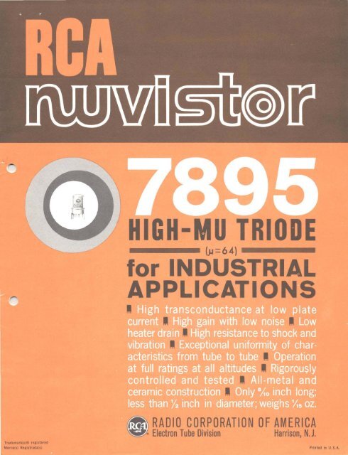
<strong>RCA</strong>-<strong>7895</strong><br />
HIGH-MU TRIODE<br />
<strong>Nuvistor</strong> Type for Industrial Applications<br />
Ampl,jicat,on Factor = 64<br />
<strong>RCA</strong>-<strong>7895</strong> is a high-mu nuvistQr triode of the heater-cathode type designed<br />
for use in a wide variety of applications In industrial equipment where<br />
compactness, low drain, negligible interface resistance, exceptional uniformity<br />
of characteristics from tube to tube, and ability to withstand<br />
severe mechanical shock and vibration are primary design requirements.<br />
It is capable of providing high gain with low noise in amplifier<br />
service, excellent stability as an oscillator over a wide range of<br />
frequencies. and reliable performance in applications such as on-off<br />
control involving long periods of standby operation.<br />
•<br />
Ac too l The <strong>7895</strong> is rigidly controlled during manufacture, and is<br />
Size<br />
subjected to rigorous tests for intermittent shorts and interelectrode<br />
leakage; for early-hour, lOO-hour, and IOOO-hour conduction life<br />
performance; for IOOO-houf standby life performance; for resistance to impact<br />
shock, low-frequency vibration, variableRfrequency vibration, low-pressure<br />
breakdown, and heater cycling.<br />
These special controls and tests, together with high transconductance at<br />
low-plate current and voltage, small power requirements, ability to operate at<br />
full ratings at any altitude, and extremely small size, make the <strong>7895</strong> nuvistor<br />
high-mu triode exceptionally desirable for critical industrial applications.<br />
General Features<br />
The <strong>7895</strong> has a metal envelope provided with two peripheral lugs of unequal<br />
width for indexing, is only 8/10" long, less than 1/2" in diameter, and weighs<br />
approximately 1/15 ounce (1.9 grams). It features (1) a very rugged structure<br />
of unique design l<br />
(2) a 6.3 volt low-wattage heater, and a specially designed<br />
cathode made of passive material to assure very low interface resistance and<br />
leakage, (3) high transconductance at low plate voltage and current (9400<br />
micromhos at 110 volts and 7.0 milliamperes), (4) very high input impedance.<br />
(5) high perveance, and (6) ability to operate at full ratings at any altitude.<br />
•<br />
Structural Features<br />
A major feature of the <strong>7895</strong> is its all-ceramic-and-metal construction<br />
utilizing a light-weight, cantilever-supported cylindrical electrode structure.<br />
This unique type of electrode structure, inherent in the nuvistor design, uses<br />
© 1961 by Radio Corporation of Ame.ico<br />
All Rl;t'lh Re.e....ed - 2 - 2-61
<strong>7895</strong><br />
Structural Features (Cont'd)<br />
only strong metals and ceramics to provide a structure of extreme ruggedness.<br />
All connections are brazed at very high temperatures in a hydrogen atmosphere<br />
to eliminate the structural strain and element distortion often caused by<br />
welding. The tube is also exhausted and sealed at very high temperatures to<br />
eliminate the gases and impurities which are generally present in electron<br />
devices processed at low temperatures.<br />
The structure of the <strong>7895</strong> nuvistor triode also permits automatic assembly<br />
using parts made to extremely small tolerances, thus assuring exceptional<br />
uniformity of characteristics from tube to tube.<br />
Electrical:<br />
GENERAL DATA<br />
•<br />
Heater, for lJnipotential Cathode:<br />
Voltage (ac or del . 6.3 ± 10% volts<br />
Current at 6.3 volts. . . . .. . . O. 135 amp<br />
Direct Interelectrode Capacitances (Approx.):<br />
Grid to plate . 0.9 IJ+Lf<br />
Grid to cathode, heater, and shell. 4.2 I"l"f<br />
Plate to cathode, heater, and shell 1.7 I"l"f<br />
Heater to cathode 1.3 IJ+Lf<br />
Plate to cathode. 0.22 IJ+Lf<br />
Characteristics, Class AI<br />
Amplifier:<br />
Plate-Supply Voltage. 110 volts<br />
Grid-Supply Voltage. 0 volts<br />
Cathode Resistor... 150 ohms<br />
Amplification Factor. 64<br />
Plate Resistance (Approx. I. 6800 ohms<br />
Transconductance . 9400 ,umhos<br />
Plate Current . 7.0 ma<br />
Grid Voltage (Approx.) for plate current = 10 I"a. -4 VD 1ts<br />
•<br />
Mechan i ca I :<br />
Operating Position.<br />
. . Any<br />
Maximum Over-all Length . O.8 11<br />
Maximum Seated Length 0.625"<br />
Maximum Diameter. 0.440"<br />
Envelope.<br />
.Metal Shell<br />
Base..<br />
.Medium Ceramic-Wafer Twelvar 5-Pin (JEDEC No.E5-65)<br />
Socke t. . ... Cinch Mfg. Co. No. 133 65 10 001, or Equivalent<br />
INDUSTRIAL SERVICE<br />
Maximum Ratings, Absolute-Maximum Values:<br />
For Operation atAny Altitude<br />
PLATE SUPPLY VOLTAGE. 330 max. val ts<br />
PLATE VOLTAGE . 110 max. volts<br />
GRID VOLTAGE:<br />
Negative-bias value 55 max. volts<br />
Peak positive value 2 max. volts<br />
- 3
<strong>7895</strong><br />
PLATE DISSIPATION 1 max. watt<br />
GRID CURRENT. . . 2 max. ma<br />
CATHODE CliRRENT . 15 max. ma<br />
PEAK HEATER-CATHODE VOLTAGE:<br />
Heater negative with respect to cathode 100 max. volts<br />
Heater positive with respect to cathode 100 max. volts<br />
Maximum Circuit Values:<br />
Grid-Circuit Resistance: •<br />
For fixed-bias operation. 0.5 max. megohm<br />
For cathode-bias operation. 1 max. megohm<br />
* For Operation at Metal-Shell Temperatures up to 150 0 C (See Dimensional Outline Drawing on<br />
Page 9).<br />
CHARACTERISTICS RANGE VALUES FOR EQUIPMENT DESIGN<br />
Note Min. Max.<br />
Heater Current. 1 0.125 0.145 amp<br />
Direct Interelectrode Capacitances:<br />
Grid to plate 2 0.8 1.0<br />
Grid to cathode, heater, and shell. 2 3.4 5.0<br />
•<br />
Plate to cathode, heater, and shell 2 1.3 2. 1<br />
Heater to cathode 2 1.0 1.6<br />
Plate to cathode. 2 . 16 .28<br />
Plate Current (1) 1,3 5.5 8.8 ma<br />
Plate Current (2) 1,4 50 !J.a<br />
Transconductance {I). 1,3 7900 10900 !J.mhos<br />
Transconductance (2). 3,5 6900 !J.mhos<br />
Transconductance Change:<br />
Difference between Transconductance<br />
0) and Transconductance (2), expressed<br />
1n per cent of Transconductance<br />
0) 15 %<br />
Reverse Grid Current. 1,6 0.1 !J.a<br />
Amplification Factor. 1,3 54 74<br />
Heater-Cathode Leakage Current:<br />
Heater negative with respect to cathode 1,7 5<br />
Heater positive with respect to cathode 1,7 5<br />
Leakage Resistance:<br />
Between grid and all other electrodes<br />
tied together 1,8 1000 megohms<br />
Between plate and all other electrodes<br />
tied together 1,9 1000 megohms<br />
Note 1:<br />
Note 2:<br />
Note 3 :<br />
Note 4:<br />
Note 5:<br />
With 6.3 volts ac or dc on heater.<br />
Measured in accordance with EIA Standard RS-191-A.<br />
With de plate volts = 110, cathode resistor = 150 ohms, and cathodebypass<br />
capacitor = 1000 !J.f,<br />
With de plate volts = 110, de grid volts = -5, and metal shell grounded.<br />
With 5.7 volts ac or dc on heater.<br />
Note 6: With de plate volts = ISO, grid-supply volts = -1.7, grid resistor =<br />
0.5 megohm, and metal shell grounded.<br />
•<br />
- 4
<strong>7895</strong><br />
Note 7 :<br />
Note 8:<br />
Note 9:<br />
With 100 volts de applied between heater and cathode.<br />
With grid 100 volts negative with respect to all other electrodes<br />
tied together.<br />
With plate 300 volts negative with respect to all other electrodes<br />
tied together.<br />
Shock Rat i ng:<br />
SPEC IAL RATI NGS AND PERFORMANCE DATA<br />
Impact Acceleration 1000 max. g<br />
This test is performed on a sample lot of tubes from each production run<br />
to determine ability of tube to withstand the specified impact acceleration.<br />
Tubes are held rigid in four different positions in a Navy Type, High-impact<br />
(flyweight) Shock Machine and are subjected to 20 blows at the specified maximum<br />
impact acceleration. At the end of this test, tubes are criticized for change<br />
in transconductance, reverse grid current, and heater-cathode leakage current,<br />
and are then subjected to the Variable-Frequency Vibration Test described later.<br />
• Fatigue Rating:<br />
Vibrational Acceleration. 2.5 max. g<br />
This test is performed on a sample lot of tubes to determine ability of<br />
tube to withstand the specified vibrational acceleration. Tubes are rigidly<br />
mounted, supplied with normal heater voltage only, and subjected for 48 hours<br />
to 2.5 g vibrational acceleration at 60 cycles per second in a direction<br />
perpendicular to the longitudinal axis of the tube. At the end of this test,<br />
tubes are criticized for the same characteristics and end-point values as in<br />
the Shock Rating Test described previously.<br />
Variable-Frequency-Vibration Performance:<br />
This test is performed on a sample lot of tubes from each production run.<br />
The tube is operated under the conditions specified in CHARACTERISTICS RANGE<br />
VALUES for Transconductance (1) with the addition of a plate-load resistor of<br />
2000 ohms. During operation I tube is vibrated in a direction perpendicular to<br />
the longitudinal axis of the tube through the frequency range from 50 to 15000<br />
•<br />
cycles per second under the following conditions: a sweep rate of one octave<br />
per 30 seconds from 50 to 3000 cps, a 7-second sweep from 3000 to 15000 cps,<br />
and a constant vibrational .acceleration of Ig. During the test, tube must not<br />
show an rms output voltage in excess of:<br />
35 mv over the frequency range from 50 to 3000 cps<br />
60 mv over the frequency range from 3000 to 6000 cps<br />
500 mv over the frequency range from 6000 to 15000 cps<br />
Low-Pressure Voltage-Breakdown Test:<br />
This test is performed on a sample lot of tubes from each production run.<br />
In this test tubes are operated with 240 rms volts applied between plate and<br />
all other electrodes and will not break down or show evidence of corona when<br />
subjected to air pressures equivalent to altitudes of up to 100000 feet.<br />
Heater Cyc! ing:<br />
Cycles of Intermittent Operation. 2000 min. cycles<br />
This test is performed on a sample lot of tubes from each production run<br />
under the following conditions: heater volts = 7.5 cycled one minute on and<br />
two minutes off; heater 100 volts negative with respect to cathode; grid, plate,<br />
- 5
<strong>7895</strong><br />
and metal shell connected to ground. At the end of this test tubes are tested<br />
for open heaters, heater-cathode shorts, and heater-cathode leakage current.<br />
Intermittent Shorts:<br />
This test is performed on a sample lot of tubes from each production run.<br />
Tubes are subjected to the Thyratron-Type Shorts Test described in MIL-E-ID,<br />
Amendment 2, Par. 4.7.7. except that tapping is done by hand with a soft rubber<br />
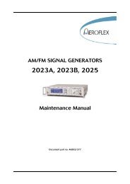
tapper·. The Acceptance Curve for this test is shown in Fig.3. In this test<br />
tubes are criticized for permanent or temporary shorts and open circuits.<br />
Early-Hour-Stabil ity Life Performance:<br />
This test is performed on a sample lot of tubes from each production run to<br />
insure that tubes are properly stabilized. In this test tubes are operated for<br />
20 hours at maximum rated plate dissipation. After 2 hours of operation and<br />
again after 20 hours of operation tubes are checked for transconductance under<br />
the conditions specified in CHARACTERISTICS RANGE VALUES for Transconductance<br />
(1). A tube is rejected if its transconductance after 2 or 20 hours of<br />
operation has changed more than 10 per cent from the O·hour value.<br />
lOO-Hour Life Performance:<br />
This test is performed on a sample lot of tubes from each production run to<br />
insure a low percentage of early-hour inoperatives. Tubes are operated for 100<br />
hours at maximum rated plate dissipation, and then subjected to the Intermittent<br />
Shorts test previously described. Following this, tubes must show a value<br />
not less than 6200 micromhos for Transconductance (I), and a value not greater<br />
than 0.2 microampere for Reverse Grid Current under the conditions specified<br />
in CHARACTERISTICS RANGE VALllES.<br />
IOOO-Hour Conduction Life Performance:<br />
This test is performed on a sample lot of tubes from each production run<br />
to insure high quality of the individual tube and guard against epidemic<br />
failures due to excessive changes in any of the characteristics indicated below.<br />
In this test tubes are operated for 1000 hours at maximum rated plate dissipation<br />
with a metal-shell temperature of 150 0 C and then criticized for inoperatives,<br />
reverse grid current, heater-cathode leakage current, and leakage resistance.<br />
In addition, the average change in transconductance of the lot from the a-hour<br />
value for Transconductance (1) specified 1n CHARACTERISTICS RANGE VALUES, must<br />
not exceed 15 per cent at 500 hours, and 20 per cent at 1000 hours.<br />
IOOO-Hour Standby Life Performance:<br />
This test is performed on a sample lot of tubes from each production run.<br />
The tubes are operated for 1000 hours with only normal heater voltage applied.<br />
The tubes are then criticized for interelectrode leakage I reverse grid current,<br />
change in transconductance of individual tubes from the values at zero hours<br />
and cathode interface resistance greater than 25 ohms. Interface resistance<br />
is measured by Method B of ASTM specification F300-57T.<br />
•<br />
•<br />
I<br />
,<br />
* Spec.ifications for this tapper will be supplied on request.<br />
OPERATING CONSIDERATIONS<br />
The base pins of the <strong>7895</strong> fit the Cinch Mfg, Co. socket No. 133 65 10 001<br />
or equivalent. The socket may be mounted to hold the tube In any position.<br />
- 6
<strong>7895</strong><br />
The maximum ratings in the tabulated data are established in accordance<br />
with the following definition of the Absolute-Maximum Rating System for rating<br />
electron devices.<br />
Absolute-Maximum ratings are limiting values of ~operating and environmental<br />
conditions applicable to any electron device of a specified type as defined by<br />
its published data, and should not be exceeded under the worst probable conditions.<br />
The device manufacturer chooses these values to provide acceptable serviceability<br />
of the device, taking no responsibility for equipment variations,<br />
environment variations, and the effects of changes In operating conditions due<br />
to variations in device characteristics.<br />
The equipment manufacturer should design so that initially and throughout<br />
life no absolute-maximum value for the intended service is exceeded with any<br />
device under the worst probable operating conditions with respect to supplyvoltage<br />
variation, equipment component variation. equipment control adjustment,<br />
load variation. signal variation, environmental conditions, and variations in<br />
•<br />
device characteristics .<br />
•<br />
Information furnished by <strong>RCA</strong> is believed to be accurate<br />
and reliable. However, no responsibility is assumed by<br />
<strong>RCA</strong> for its use; nor for any infringements of patents<br />
or other rights of third parties which may result from<br />
its use. No license is granted by implication or<br />
otherwise under any patent or patent rights of ReA.<br />
- 7
~_.-<br />
<strong>7895</strong><br />
E.j>::6.3 VOLTS<br />
BC<br />
'<br />
8<br />
~<br />
N 50 ~<br />
. v<br />
~<br />
"<br />
40 ~<br />
<<br />
30<br />
~<br />
><br />
~<br />
~<br />
~<br />
ooסס4 0<br />
><br />
w<br />
0<br />
20000<br />
~<br />
•<br />
It. 0<br />
~<br />
8 ~ 30000 5000~<br />
I<br />
, V<br />
'ii<br />
I<br />
E<br />
'" w<br />
v<br />
~ 20000 IOOO0tj<br />
> Z<br />
~<br />
<<br />
"<br />
•<br />
~ ~<br />
w<br />
V<br />
0<br />
o<br />
w 20<br />
V<br />
~<br />
10000 5000~<br />
-\<br />
~<br />
,<br />
0; z<br />
• < c<br />
cl 0 ,..:<br />
o -4 -, -2<br />
GRID VOLTS<br />
-, o<br />
PLATE MILLIAMflERES<br />
92CM-I0965<br />
92CM-I0967<br />
•<br />
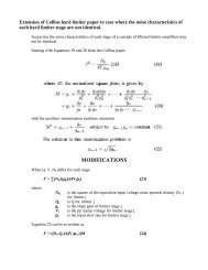
Fig.l - Average Plate Characteris tics Fig.2 - Average Charae teris tics for<br />
for Type <strong>7895</strong>. Type <strong>7895</strong>.<br />
~<br />
0<br />
z<br />
0<br />
10000,<br />
,<br />
•<br />
v ,<br />
w<br />
~<br />
~ 1000<br />
V ,<br />
, ,<br />
I<br />
~ •<br />
• 0<br />
I<br />
,<br />
~<br />
" 0 '00<br />
z 0 ,<br />
./<br />
<<br />
4<br />
AREA OF ACCEPTABILITY<br />
"• 0 ,<br />
1',', 1 I 11<br />
'0 I1II I 11 11<br />
, • , , , • , , , , , ,<br />
10 100 1000<br />
RESISTANCE or:- SHORT-OHMS XIOOO<br />
92CS-I0465<br />
•<br />
Fig.3 - Thyratron-Type Shorts Test for<br />
Type <strong>7895</strong>.<br />
- B
<strong>7895</strong><br />
DIMENSIONAL OUTLINE<br />
~1<br />
.400"".~X. DIA.~<br />
·2:00 MIN. i<br />
OIA. FLAT<br />
METAL<br />
SHELL<br />
•<br />
~.435"MAX.<br />
BASE<br />
JEOEC Ng £5-6,5<br />
• lOON MIN•<br />
.130"MAX.<br />
,-<br />
I<br />
.5 PINS<br />
.0Ib".2: .001" OIA.<br />
~<br />
---L<br />
--r<br />
ZONE 'A'<br />
r-..".---rr..".--..".--" I\'I°TE 2)t<br />
DIA.---l<br />
(NOTE I)<br />
.190"<br />
CERAMIC<br />
/WAl"TR<br />
.800"<br />
MAX.<br />
I<br />
lARGE_<br />
LUG<br />
SMAll<br />
LUG<br />
e=PIN CUT OFF<br />
92C$-IOQ70<br />
•<br />
BASING<br />
PIN I:<br />
..<br />
PIN 3:<br />
..<br />
PIN<br />
..<br />
5:<br />
..<br />
PIN 2: PLATE<br />
PIN 4: GRID<br />
PIN 6:<br />
HOTEl: MAXIMUM O.D. OF 0.440" IS PERMITIEO<br />
ALONG 0.190" LUG LENGTIf.<br />
HOTE 2: SHELL TEMPERATURE SHOUUJ BE MEASURED<br />
IN ZONE "A' BETWEEN BROKEN LINES •<br />
DIAGRAM (Bottom View)<br />
4<br />
G<br />
INDEX=LARGE LUG<br />
• = PIN CUT OFT<br />
IZAQ<br />
..<br />
..<br />
PIN 7:<br />
PIN B: CATIfOOE<br />
PIN 9:<br />
PIN 10: HEATER<br />
PIN 11: OMITTED<br />
PIN 12: HEATER<br />
A Pin has internal connection and is cut<br />
off close to ceramic wafera-Do Not Use.<br />
- 9 -
<strong>7895</strong><br />
MEDIUM CERAMIC-WAFER TWELVAR BASE<br />
SOCKET INSERTION<br />
PLANE<br />
I<br />
.040 0 MAX.<br />
! , .I00"MIN•<br />
190"+·020;' :<br />
• -.015 I<br />
•13o"MAX.<br />
METAL SHELL<br />
~ : ~ BASE SEATING<br />
r--1r--- AOO" MIN. I. D. :1<br />
PLANE<br />
,/;:';'"A<br />
.~I?:'" rA35" MAX. 0.0.<br />
ALL PINS<br />
INDEX GUIDE .016" ± .001"<br />
LARGE LUG<br />
alA.<br />
\, \<br />
60 60 0 CERAMIC<br />
'- \<br />
'1;;.,+<br />
WAFER<br />
-,--SMALL LUG<br />
60·<br />
.280"OIA.<br />
•210"01A•<br />
• 140"'OIA•<br />
• 070 lA.<br />
•<br />
92CM-I0478RI<br />
JEDEC No. NAME PINS<br />
E12-64 12·Pin Base 1,2,3,4,5.6,7,8,<br />
9,10,11,12<br />
E5-65 5-Pin Base 2,4,8,10,12,<br />
(Note 2)<br />
Note I: Maximum 0.0. of 0.440" is permitted along the<br />
0.190" lug length.<br />
Note 2: Pins 1.3,5,6,7, and9arecut off to a length such<br />
that their ends do not touch the socket insertion plane.<br />
Pin 11 is omitted.<br />
PIN-ALIGNMENT GAUGE<br />
Base·pin positions and lug positions shall be held to<br />
tolerances such that entire length of pins and lugs will<br />
without undue force pass into and disengage from flat.<br />
plate gauge havin~ thickness of 0.25" and twelve holes of<br />
0.0350" ± 0.0005 diameter located on four concentric<br />
circles as follows: Three holes located on 0.2800 R ±<br />
0.0005 R , th:reeholes located on 0.2100 R ± 0.0005 R , three<br />
holes located on 0.1400· ± 0.0005", three holes located<br />
on 0.0700" ± 0.0005" diameter circles at specified angles<br />
with a tolerance of ± 0.08 0 for each angle. In additIon,<br />
gauge provides for two curved slots with chordal lengths<br />
of 0.2270" ± 0.0005" and 0.1450" ± 0.0005" located on<br />
0:4200" ± 0.0005" diamster circ~e conc~ntric witll pin<br />
cIrcles at 180 0 ± 0.08 and havIng a wIdth of 0.0230"<br />
± 0.0005".<br />
•<br />
- 10
<strong>7895</strong><br />
CATHODE--+-<br />
---f1-- HEATER<br />
!'---tt--PLATE<br />
GRID -f-"o-"";<br />
METAL SHELL<br />
•<br />
CERAMIC<br />
BASE WAFER<br />
•<br />
Fig.4 ~<br />
INDEXING<br />
LUGS<br />
Illustration of a nuvistor triode showing cylindrical electrodes<br />
and tripod-like supports.<br />
- 11 -

![[6]](https://img.yumpu.com/23901941/1/184x260/6.jpg?quality=85)