Line components Contents Page - Erawan Refrigeration Co., Ltd.
Line components Contents Page - Erawan Refrigeration Co., Ltd.
Line components Contents Page - Erawan Refrigeration Co., Ltd.

Create successful ePaper yourself
Turn your PDF publications into a flip-book with our unique Google optimized e-Paper software.
<strong>Line</strong> <strong>components</strong><br />
<strong><strong>Co</strong>ntents</strong><br />
<strong>Page</strong><br />
Eliminator Ò Liquid line filter driers, type DCL and DML<br />
Introduction .................................................................................................................................. 5<br />
Approvals ..................................................................................................................................... 5<br />
Features ....................................................................................................................................... 5<br />
Technical data .............................................................................................................................. 6<br />
Capacities .................................................................................................................................... 6<br />
Ordering ....................................................................................................................................... 8<br />
Identification ................................................................................................................................. 9<br />
Selection ...................................................................................................................................... 9<br />
Selection example .................................................................................................................. 9<br />
Design and function ................................................................................................................... 10<br />
Dimensions and weights:<br />
Flare connections ................................................................................................................. 11<br />
Solder connections ............................................................................................................... 12<br />
Filter drier with interchangeable solid core, type DCR<br />
Introduction ................................................................................................................................ 13<br />
Features ..................................................................................................................................... 13<br />
Approvals ................................................................................................................................... 13<br />
Technical data ............................................................................................................................ 13<br />
Solid core ................................................................................................................................... 14<br />
Capacity ..................................................................................................................................... 14<br />
Ordering ..................................................................................................................................... 16<br />
<strong>Co</strong>nstruction / Function .............................................................................................................. 17<br />
Dimensions and weights ............................................................................................................ 18<br />
Bi-flow filter drier, type DMB/DCB<br />
Introduction ................................................................................................................................ 19<br />
Features ..................................................................................................................................... 19<br />
Approvals ................................................................................................................................... 19<br />
Technical data ............................................................................................................................ 19<br />
<strong>Co</strong>nstruction / flow direction ....................................................................................................... 20<br />
Capacities .................................................................................................................................. 20<br />
Selection example ...................................................................................................................... 22<br />
Ordering DMB / DCB ................................................................................................................. 23<br />
Dimensions and weights for DMB / DCB ................................................................................... 24<br />
Eliminator Ò Burnoutfilter, type DAS<br />
Introduction ................................................................................................................................ 25<br />
Features ..................................................................................................................................... 25<br />
Approvals ................................................................................................................................... 25<br />
Ordering ..................................................................................................................................... 25<br />
Capacities .................................................................................................................................. 26<br />
Identification ............................................................................................................................... 26<br />
Design and function ................................................................................................................... 27<br />
Dimensions and weights ............................................................................................................ 27<br />
<strong>Co</strong>mbined filter drier and receiver, type DCC and DMC<br />
Introduction ................................................................................................................................ 29<br />
Features ..................................................................................................................................... 29<br />
Technical data ............................................................................................................................ 29<br />
Capacity ..................................................................................................................................... 30<br />
Ordering ..................................................................................................................................... 30<br />
Dimensions and weights ............................................................................................................ 30<br />
© Danfoss A/S (RC-CM / MWA), 05 - 2002 RK0YE102 1
<strong>Line</strong> <strong>components</strong><br />
<strong><strong>Co</strong>ntents</strong><br />
<strong>Page</strong><br />
Flare / solder adapter, type FSA<br />
Introduction ................................................................................................................................ 31<br />
Application ................................................................................................................................. 31<br />
Standards ................................................................................................................................... 31<br />
Technical data ............................................................................................................................ 31<br />
Type designation ........................................................................................................................ 31<br />
Ordering ..................................................................................................................................... 32<br />
Dimensions and weight .............................................................................................................. 32<br />
Sight glasses, type SGI, SGN, SGR and SGRN<br />
Introduction ................................................................................................................................ 33<br />
Features ..................................................................................................................................... 33<br />
Choice of sight glass .................................................................................................................. 33<br />
Technical data ............................................................................................................................ 34<br />
Ordering ..................................................................................................................................... 35<br />
Dimensions and weights ............................................................................................................ 36<br />
Check valves, type NRV and NRVH<br />
Introduction ................................................................................................................................ 37<br />
Features ..................................................................................................................................... 37<br />
Technical data ............................................................................................................................ 37<br />
Dimensioning and selection ....................................................................................................... 37<br />
Ordering ..................................................................................................................................... 38<br />
Capacity ..................................................................................................................................... 39<br />
Dimensions and weights ............................................................................................................ 41<br />
Shut-off valves, type BM<br />
Introduction ................................................................................................................................ 43<br />
Features ..................................................................................................................................... 43<br />
Technical data ............................................................................................................................ 43<br />
Ordering ..................................................................................................................................... 43<br />
Design / Function ...................................................................................................................... 44<br />
Dimensions and weights .......................................................................................................... 45<br />
Shut-off valves, type GVC<br />
Introduction ................................................................................................................................ 47<br />
Technical data ............................................................................................................................ 47<br />
Ordering ..................................................................................................................................... 47<br />
Spareparts / Accessories ...................................................................................................... 47<br />
Design ........................................................................................................................................ 48<br />
Dimensions and weights ............................................................................................................ 48<br />
Ball valve, type GBC<br />
Introduction ................................................................................................................................ 49<br />
Features ..................................................................................................................................... 49<br />
Technical data ............................................................................................................................ 49<br />
Ordering ..................................................................................................................................... 50<br />
<strong>Co</strong>nstruction ............................................................................................................................... 50<br />
Dimensions and weights ............................................................................................................ 51<br />
2 RK0YE102 © Danfoss A/S (RC-CM / MWA), 05 - 2002
<strong>Line</strong> <strong>components</strong><br />
<strong><strong>Co</strong>ntents</strong><br />
<strong>Page</strong><br />
Oil separators, type OUB<br />
Introduction ................................................................................................................................ 53<br />
Features ..................................................................................................................................... 53<br />
Approvals ................................................................................................................................... 53<br />
Technical data ............................................................................................................................ 53<br />
Ordering ..................................................................................................................................... 54<br />
Design / Function ....................................................................................................................... 54<br />
Dimensions and weights ............................................................................................................ 55<br />
Heat exchangers, type HE<br />
Introduction ................................................................................................................................ 57<br />
Features ..................................................................................................................................... 57<br />
Technical data ............................................................................................................................ 57<br />
Ordering ..................................................................................................................................... 57<br />
Capacity ..................................................................................................................................... 58<br />
Design / Function ....................................................................................................................... 59<br />
Dimensions and weights ............................................................................................................ 59<br />
© Danfoss A/S (RC-CM / MWA), 05 - 2002 RK0YE102 3
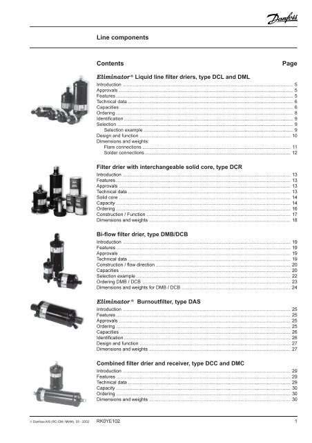
Eliminator Ò Liquid line filter driers,<br />
type DCL and DML<br />
Introduction<br />
Eliminator Ò liquid line filter driers protect<br />
refrigeration and air-conditioning systems<br />
from moisture, acids, and solid particles.<br />
With these contaminants eliminated,<br />
systems are safer from harmful chemical<br />
reactions and from abrasive impurities.<br />
There are two types of Eliminator Ò cores.<br />
Type DML driers have a core composition of<br />
100% molecular sieves, while type DCL<br />
contain 80% molecular sieves with 20%<br />
activated alumina.<br />
All Eliminator Ò driers have a solid core<br />
with binding material held to an absolute<br />
minimum. <strong>Co</strong>re selection is primarily based<br />
on the refrigerant oil used in the system.<br />
Eliminator Ò type DML, with a solid core of<br />
100% molecular sieves, is optimized for use<br />
with HFC refrigerants and polyolester (POE)<br />
or polyalkyl glycol (PAG) oils. Type DML driers<br />
are designed for applications requiring high<br />
water adsorption, and can be used with any<br />
manufacturer’s compressor. Because type<br />
DML driers contain no activated alumina, oil<br />
additives will not be depleted.<br />
Eliminator Ò type DCL, with a solid core of<br />
80% molecular sieves and 20% activated<br />
alumina, is the drier of choice for systems<br />
with HCFC and CFC refrigerants and mineral<br />
or alkyl benzene oils. Type DCL driers are<br />
particularly suited for systems that operate at<br />
high condensing temperatures and require<br />
high drying capacity.<br />
Features<br />
The <strong>Co</strong>re<br />
Type DML<br />
• 100% 3Å molecular sieves core.<br />
• High drying capacity minimizing the risk of<br />
acid formation (hydrolysis).<br />
• Optimized for HFC refrigerants (R 134a,<br />
R 404A, R 410A, etc.) with POE or PAG oils.<br />
<strong>Co</strong>mpatible with R 22.<br />
• Will not deplete oil additives.<br />
Type DCL<br />
• 80% 3Å molecular sieves with 20%<br />
activated alumina.<br />
• Perfect core blend for systems that operate<br />
at high condensing temperatures and<br />
require high drying capacity.<br />
• Optimized for CFC and HCFC refrigerants<br />
(R 22, R 502, etc.) with mineral or alkyl<br />
benzene oils. <strong>Co</strong>mpatible with HFC’s and<br />
refrigerant blends.<br />
The Shell<br />
• UL approved for MWP up to 42 bar.<br />
• Available with solder (Cu-plated steel<br />
connectors) and flare connections.<br />
• <strong>Co</strong>mpact 3 cubic inches drier ideal for<br />
refrigeration and air conditioning units.<br />
• <strong>Co</strong>rrosion resistant powder-painted finish.<br />
Can be used in all environments including<br />
marine applications.<br />
• Allows installation with any orientation<br />
provided the arrow is in the flow direction.<br />
• Available in sizes from 3 to 75 cubic<br />
inches.<br />
The Filter<br />
• 25 µm filter provides high retention with<br />
minimal pressure drop.<br />
• Thermally stable up to 120°C.<br />
Approvals cSUS UL file no. SA 6398<br />
PED 97/23/EC - a3p3<br />
© Danfoss A/S (RC-CM / MWA), 06 - 2002 Technical leaflet - RD6AM302 5
Eliminator Ò Liquid line filter driers, type DCL and DML<br />
Technical data<br />
Surface and volume<br />
Solid core Solid core Filter drier DCL acid<br />
Filter surface volume volume capacity<br />
[cm 2 ] [cm 3 ] [l] [g]<br />
DML/DCL 03 65 41 0.08 0.58<br />
DML/DCL 05 75 65 0.12 0.87<br />
DML/DCL 08 110 100 0.17 1.36<br />
DML/DCL 16 175 225 0.38 3.12<br />
DML/DCL 30 330 480 0.67 6.40<br />
DML/DCL 41 400 650 0.90 8.90<br />
DML/DCL 60 660 960 1.3412.80<br />
DML/DCL 75 800 1300 1.75 17.80<br />
Temperature range – 40 to 70°C<br />
Technical data and<br />
capacities<br />
1 ) Drying capacity is based on<br />
following moisture content test<br />
standards before and after<br />
drying:<br />
R 134a: From 1050 ppm W to 75<br />
ppm W. If drying to 50 ppm W is<br />
required, reduce stated<br />
capacities by 15%.<br />
R 404A, R 507: From 1020 ppm<br />
W to 30 ppm W.<br />
R 407C: From 1020 ppm W to 30<br />
ppm W.<br />
R 410A: From 1050 ppm W to 60<br />
ppm W.<br />
R 22: From 1050 ppm W to 60<br />
ppm W in accordance with ARI<br />
710-86.<br />
R 12: From 565 ppm W to 15<br />
ppm W in accordance with ARI<br />
710-86.<br />
R 502: From 1020 ppm W to 30<br />
ppm W in accordance with ARI<br />
710-86.<br />
2 ) Given in accordance with<br />
ARI 710-86 for t e = –15°C, t c =<br />
30°C and ∆p = 0.07 bar.<br />
DML<br />
Drying and liquid capacity - Type DML<br />
Type<br />
R 134a<br />
R 507<br />
R 404A<br />
R 22<br />
R 407C<br />
R 410A<br />
R 134a, R 507, R 404A,<br />
R 22, R 407C, R 410A<br />
Drying capacity [kg refrigerant] 1 ) Liquid capacity [kW] 2 ) Max<br />
R 134a<br />
R 404A<br />
R 507<br />
R 22<br />
R 407C<br />
R 410A<br />
Working<br />
Pressure<br />
PB<br />
[bar]<br />
24 °C 52 °C 24 °C 52 °C 24 °C 52 °C<br />
DML 032/032s 5.5 5 7.5 4.5 4.5 4 7 5 7 42<br />
DML 032.5s 5.5 5 7.5 4.5 4.5 4 9 7 10 42<br />
DML 033/033s 5.5 5 7.5 4.5 4.5 4 17 13 19 42<br />
DML 034s 5.5 5 7.5 4.5 4.5 4 24 17 26 42<br />
DML 052/052s 8.5 8 13 7.5 8 7 7 5 8 42<br />
DML 052.5s 8.5 8 13 7.5 8 7 9 7 10 42<br />
DML 053/053s 8.5 8 13 7.5 8 7 18 1419 42<br />
DML 054s 8.5 8 13 7.5 8 7 25 18 27 42<br />
DML 055s 8.5 8 13 7.5 8 7 3425 38 42<br />
DML 082/082s 12.5 12 20 11.5 12.5 11 7 5 8 42<br />
DML 082.5s 12.5 12 20 11.5 12.5 11 10 8 11 42<br />
DML 083/083s 12.5 12 20 11.5 12.5 11 19 1421 42<br />
DML 084/084s 12.5 12 20 11.5 12.5 11 26 20 29 42<br />
DML 085/085s 12.5 12 20 11.5 12.5 11 42 31 46 42<br />
DML 162/162s 27 25.5 43.5 24 27 23 7 5 8 42<br />
DML 162.5s 27 25.5 43.5 24 27 23 10 8 11 42<br />
DML 163/163s 27 25.5 43.5 24 27 23 22 16 24 42<br />
DML 164/164s 27 25.5 43.5 24 27 23 30 22 33 42<br />
DML 165/165s 27 25.5 43.5 24 27 23 43 30 47 42<br />
DML 166/166s 27 25.5 43.5 24 27 23 44 31 48 42<br />
DML 167s 27 25.5 43.5 24 27 23 44 31 48 42<br />
DML 303/303s 57 54 92.5 51 57 48.5 21 15 23 42<br />
DML 304/304s 57 5492.5 51 57 48.5 31 22 34 42<br />
DML 305/305s 57 54 92.5 51 57 48.5 45 33 49 42<br />
DML 306/306s 57 54 92.5 51 57 48.5 62 45 68 42<br />
DML 307s 57 54 92.5 51 57 48.5 62 45 68 42<br />
DML 309s 57 54 92.5 51 57 48.5 62 45 68 42<br />
DML 413 80 75 130 70 80 74 25 18 27 42<br />
DML 414/414s 80 75 130 70 80 74 32 23 35 42<br />
DML 415/415s 80 75 130 70 80 74 53 37 58 42<br />
DML 417s 80 75 130 70 80 74 91 65 100 42<br />
DML 419s 80 75 130 70 80 74 91 65 100 42<br />
DML 604s 113 107 185 101 114 97 27 20 31 42<br />
DML 606s 113 107 185 101 114 97 44 32 48 42<br />
DML 607s 113 107 185 101 11497 75 5482 42<br />
DML 609s 113 107 185 101 11497 87 6495 42<br />
DML 757s 160 150 260 140 160 148 82 60 90 42<br />
DML 759s 160 150 260 140 160 148 94 68 102 42<br />
6 Technical leaflet - RD6AM302 © Danfoss A/S (RC-CM / MWA), 06 - 2002
Eliminator Ò Liquid line filter driers, type DCL and DML<br />
Technical data<br />
and capacities<br />
(continued)<br />
1 ) Drying capacity is based on<br />
following moisture content test<br />
standards before and after<br />
drying:<br />
R 134a: From 1050 ppm W to 75<br />
ppm W. If drying to 50 ppm W is<br />
required, reduce stated<br />
capacities by 15%.<br />
R 404A, R 507: From 1020 ppm<br />
W to 30 ppm W.<br />
R 407C: From 1020 ppm W to 30<br />
ppm W.<br />
R 410A: From 1050 ppm W to 60<br />
ppm W.<br />
R 22: From 1050 ppm W to 60<br />
ppm W in accordance with ARI<br />
710-86.<br />
R 12: From 565 ppm W to 15<br />
ppm W in accordance with ARI<br />
710-86.<br />
R 502: From 1020 ppm W to 30<br />
ppm W in accordance with ARI<br />
710-86.<br />
2 ) Given in accordance with<br />
ARI 710-86 for t e = –15°C, t c =<br />
30°C and ∆p = 0.07 bar.<br />
DCL<br />
Drying and liquid capacity - Type DCL<br />
Type<br />
R 134a<br />
R 507<br />
R 404A<br />
R 407C<br />
R 410A<br />
24 °C 52 °C 24 °C 52 °C 24 °C 52 °C<br />
R 134a, R 507, R 404A,<br />
R 407C, R 410A<br />
Drying capacity [kg refrigerant] 1 ) Liquid capacity [kW] 2 )<br />
R 134a<br />
R 404A<br />
R 507<br />
R 407C<br />
R 410A<br />
Max<br />
Working<br />
Pressure<br />
PB<br />
[bar]<br />
DCL 032/032s 4.5 4 7 3.5 4 3.5 7 5 7 42<br />
DCL 032.5s 4.5 4 7 3.5 4 3.5 9 7 10 42<br />
DCL 033/033s 4.5 4 7 3.5 4 3.5 17 13 19 42<br />
DCL 052/052s 6.5 6 10 5.5 6 5.5 7 5 8 42<br />
DCL 052.5s 6.5 6 10 5.5 6 5.5 9 7 10 42<br />
DCL 053/053s 6.5 6 10 5.5 6 5.5 18 1419 42<br />
DCL 082/082s 10 9 16 8 9.5 9 7 5 8 42<br />
DCL 082.5s 10 9 16 8 9.5 9 10 8 11 42<br />
DCL 083/083s 10 9 16 8 9.5 9 19 1421 42<br />
DCL 084/084s 10 9 16 8 9.5 9 26 20 29 42<br />
DCL 162/162s 2422 37 20 22 20 7 5 8 42<br />
DCL 162.5s 2422 37 20 22 20 10 8 11 42<br />
DCL 163/163s 2422 37 20 22 20 22 16 24 42<br />
DCL 164/164s 24 22 37 20 22 20 30 22 33 42<br />
DCL 165/165s 24 22 37 20 22 20 43 30 47 42<br />
DCL 166/166s 24 22 37 20 22 20 43 30 47 42<br />
DCL 167s 24 22 37 20 22 20 43 30 47 42<br />
DCL 303/303s 47 44 77 41 44 41 21 15 23 42<br />
DCL 304/304s 47 44 77 41 44 41 31 22 34 42<br />
DCL 305/305s 47 44 77 41 44 41 45 33 49 42<br />
DCL 306/306s 47 44 77 41 44 41 62 45 68 42<br />
DCL 307s 47 44 77 41 44 41 62 45 68 42<br />
DCL 309s 47 44 77 41 44 41 62 45 68 42<br />
DCL 413 65 61 106 56 61 56 25 18 27 42<br />
DCL 414/414s 65 61 106 56 61 56 32 23 35 42<br />
DCL 415/415s 65 61 106 56 61 56 53 37 58 42<br />
DCL 417s 65 61 106 56 61 56 91 65 100 42<br />
DCL 419s 65 61 106 56 61 56 91 65 100 42<br />
DCL 604s 94 76 150 82 89 82 27 20 31 42<br />
DCL 607s 9476 150 82 89 82 75 5482 42<br />
DCL 609s 9476 150 82 89 82 87 6492 42<br />
DCL 757s 130 128 212 114121 112 82 60 90 42<br />
DCL 759s 130 128 212 114121 112 94 68 102 42<br />
DCL<br />
Drying and liquid capacity - Type DCL<br />
Type<br />
Drying capacity [kg refrigerant] 1 )<br />
R 22 R 12 R 502<br />
24 °C 52°C 24 °C 52 °C 24 °C 52 °C<br />
R 22, R 12, R 502<br />
Liquid capacity [kW] 2 )<br />
R 22 R 12 R 502<br />
Max<br />
Working<br />
Pressure<br />
[bar]<br />
DCL 032/032s 43.5 15 15 7 3.5 7 6 5 42<br />
DCL 032.5s 43.5 15 15 7 3.5 10 8 7 42<br />
DCL 033/033s 43.5 15 15 7 3.5 19 1413 42<br />
DCL 052/052s 5.5 5 20 20 10 5 8 6 5 42<br />
DCL 052.5s 5.5 5 20 20 10 5 10 8 8 42<br />
DCL 053/053s 5.5 5 20 20 10 5 19 15 1442<br />
DCL 082/082s 9 8 30 30 15 8 8 6 5 42<br />
DCL 082.5s 9 8 30 30 15 8 10 8 8 42<br />
DCL 083/083s 9 8 30 30 15 8 21 15 1442<br />
DCL 084/084s 9 8 30 30 15 8 29 22 20 42<br />
DCL 162/162s 20 19 70 70 35 18 8 6 5 42<br />
DCL 162.5s 20 19 70 70 35 18 13 10 9 42<br />
DCL 163/163s 20 19 70 70 35 18 2418 16 42<br />
DCL 164/164s 20 19 70 70 35 18 33 24 22 42<br />
DCL 165/165s 20 19 70 70 35 18 47 35 30 42<br />
DCL 166/166s 20 19 70 70 35 18 47 35 30 42<br />
DCL 167s 20 19 70 70 35 18 47 35 30 42<br />
DCL 303/303s 42 41 140 140 75 37.5 23 17 15 42<br />
DCL 304/304s 42 41 140 140 75 37.5 34 25 22 42<br />
DCL 305/305s 42 41 140 140 75 37.5 49 37 33 42<br />
DCL 306/306s 42 41 140 140 75 37.5 68 51 45 42<br />
DCL 307s 42 41 140 140 75 37.5 68 51 45 42<br />
DCL 309s 42 41 140 140 75 37.5 68 51 45 42<br />
DCL 413 59 56 200 200 100 50 26 20 18 42<br />
DCL 414/414s 59 56 200 200 100 50 35 26 23 42<br />
DCL 415/415s 59 56 200 200 100 50 58 43 37 42<br />
DCL 417s 59 56 200 200 100 50 100 74 65 42<br />
DCL 419s 59 56 200 200 100 50 100 74 65 42<br />
DCL 604s 84 80 250 250 150 75 29 22 19 42<br />
DCL 607s 8480 250 250 150 75 83 63 54 42<br />
DCL 609s 8480 250 250 150 75 97 73 63 42<br />
DCL 757s 120 110 300 300 200 100 91 69 59 42<br />
DCL 759s 120 110 300 300 200 100 10479 68 42<br />
© Danfoss A/S (RC-CM / MWA), 06 - 2002 Technical leaflet - RD6AM302 7
Eliminator Ò Liquid line filter driers, type DCL and DML<br />
Ordering<br />
Flare DCL Flare DML<br />
Type <strong>Co</strong>nn. <strong>Co</strong>de no. <strong>Co</strong>nn. <strong>Co</strong>de no.<br />
in.<br />
mm<br />
DCL 032* 1<br />
/4 023Z5000 6 023Z5000<br />
DCL 032 1<br />
/4 023Z5075 6 023Z5075<br />
DCL 033* 3<br />
/8 023Z5001 10 023Z5001<br />
DCL 033 3<br />
/8 023Z5089 10 023Z5089<br />
DCL 052 1<br />
/4 023Z5002 6 023Z5002<br />
DCL 053 3<br />
/8 023Z5003 10 023Z5003<br />
DCL 082 1<br />
/4 023Z5004 6 023Z5004<br />
DCL 083 3<br />
/8 023Z5005 10 023Z5005<br />
DCL 084 1<br />
/2 023Z5006 12 023Z5006<br />
DCL 162 1<br />
/4 023Z5007 6 023Z5007<br />
DCL 163 3<br />
/8 023Z5008 10 023Z5008<br />
DCL 164 1<br />
/2 023Z5009 12 023Z5009<br />
DCL 165 5<br />
/8 023Z5010 16 023Z5010<br />
DCL 166 3<br />
/ 4 023Z5011 19 023Z5011<br />
DCL 303 3<br />
/8 023Z0012 10 023Z0012<br />
DCL 304 1<br />
/2 023Z0013 12 023Z0013<br />
DCL 305 5<br />
/8 023Z0014 16 023Z0014<br />
DCL 306 3<br />
/4 023Z0156 19 023Z0156<br />
DCL 413 3<br />
/8 023Z0101 10 023Z0101<br />
DCL 414 1<br />
/2 023Z0102 12 023Z0102<br />
DCL 415 5<br />
/8 023Z0103 16 023Z0103<br />
* Wire mesh in filter drier outlet<br />
Type <strong>Co</strong>nn. <strong>Co</strong>de no. <strong>Co</strong>nn. <strong>Co</strong>de no.<br />
in.<br />
mm<br />
DML 032* 1<br />
/4 023Z5035 6 023Z5035<br />
DML 033* 3<br />
/8 023Z5036 10 023Z5036<br />
DML 033 3<br />
/8 023Z5090 10 023Z5090<br />
DML 052 1<br />
/4 023Z5037 6 023Z5037<br />
DML 053 3<br />
/8 023Z5038 10 023Z5038<br />
DML 082 1<br />
/4 023Z5039 6 023Z5039<br />
DML 083 3<br />
/8 023Z5040 10 023Z5040<br />
DML 084 1<br />
/2 023Z5041 12 023Z5041<br />
DML 085 5<br />
/8 023Z5073 16 023Z5073<br />
DML 162 1<br />
/4 023Z5042 6 023Z5042<br />
DML 163 3<br />
/8 023Z5043 10 023Z5043<br />
DML 164 1<br />
/2 023Z5044 12 023Z5044<br />
DML 165 5<br />
/8 023Z5045 16 023Z5045<br />
DML 166 3<br />
/4 023Z5046 19 023Z5046<br />
DML 303 3<br />
/8 023Z0049 10 023Z0049<br />
DML 304 1<br />
/2 023Z0050 12 023Z0050<br />
DML 305 5<br />
/8 023Z0051 16 023Z0051<br />
DML 306 3<br />
/4 023Z0193 19 023Z0193<br />
DML 413 3<br />
/8 023Z0108 10 023Z0108<br />
DML 414 1<br />
/2 023Z0109 12 023Z0109<br />
DML 415 5<br />
/8 023Z0110 16 023Z0110<br />
Solder (Cu-plated steel connectors)<br />
DCL<br />
Type <strong>Co</strong>nn. <strong>Co</strong>de no. <strong>Co</strong>nn. <strong>Co</strong>de no.<br />
in.<br />
mm<br />
DCL 032s 1<br />
/4 023Z4501 6 023Z4500<br />
DCL 032.5s 5<br />
/16 023Z4502 8 023Z4502<br />
DCL 033s 3<br />
/8 023Z4504 10 023Z4503<br />
DCL 052s 1<br />
/4 023Z4506 6 023Z4505<br />
DCL 052.5s 5<br />
/16 023Z4507 8 023Z4507<br />
DCL 053s 3<br />
/8 023Z4509 10 023Z4508<br />
DCL 082s 1<br />
/4 023Z4511 6 023Z4510<br />
DCL 082.5s 5<br />
/16 023Z4512 8 023Z4512<br />
DCL 083s 3<br />
/8 023Z4514 10 023Z4513<br />
DCL 084s 1<br />
/2 023Z4516 12 023Z4515<br />
DCL 162s 1<br />
/4 023Z4518 6 023Z4517<br />
DCL 162.5s 5<br />
/16 023Z4520 8 023Z4520<br />
DCL 163s 3<br />
/8 023Z4521 10 023Z4519<br />
DCL 164s 1<br />
/2 023Z4523 12 023Z4522<br />
DCL 165s 5<br />
/8 023Z4524 16 023Z4524<br />
DCL 166s 3<br />
/ 4 023Z4525 19 023Z4525<br />
DCL 167s 7<br />
/8 023Z4526 22 023Z4526<br />
DCL 303s 3<br />
/8 023Z4528 10 023Z4527<br />
DCL 304s 1<br />
/2 023Z4530 12 023Z4529<br />
DCL 305s 5<br />
/8 023Z4531 16 023Z4531<br />
DCL 306s 18 023Z4532<br />
DCL 306s 3<br />
/4 023Z4533 19 023Z4533<br />
DCL 307s 7<br />
/8 023Z4534 22 023Z4534<br />
DCL 309s 1 1 /8 023Z4536 28 023Z4535<br />
DCL 414s 1<br />
/2 023Z4538 12 023Z4537<br />
DCL 415s 5<br />
/8 023Z4539 16 023Z4539<br />
DCL 417s 7<br />
/8 023Z4540 22 023Z4540<br />
DCL 419s 1 1 /8 023Z4542 28 023Z4541<br />
DCL 604s 1<br />
/2 023Z4544 12 023Z4543<br />
DCL 607s 7<br />
/8 023Z4545 22 023Z4545<br />
DCL 609s 1 1 /8 023Z4547 28 023Z4546<br />
DCL 757s 7<br />
/8 023Z4548 22 023Z4548<br />
DCL 759s 1 1 /8 023Z4550 28 023Z4549<br />
Solder (Cu-plated steel connectors)<br />
DML<br />
Type <strong>Co</strong>nn. <strong>Co</strong>de no. <strong>Co</strong>nn. <strong>Co</strong>de no.<br />
in.<br />
mm<br />
DML 032s 1<br />
/4 023Z4552 6 023Z4551<br />
DML 032.5s 5<br />
/16 023Z4553 8 023Z4553<br />
DML 033s 3<br />
/8 023Z4555 10 023Z4554<br />
DML 034s 1<br />
/2 023Z4556 12 023Z4557<br />
DML 052s 1<br />
/4 023Z4559 6 023Z4558<br />
DML 052.5s 5<br />
/16 023Z4560 8 023Z4560<br />
DML 053s 3<br />
/8 023Z4562 10 023Z4561<br />
DML 054s 1<br />
/2 023Z4564 12 023Z4563<br />
DML 055s 5<br />
/8 023Z4565 16 023Z4565<br />
DML 082s 1<br />
/4 023Z4567 6 023Z4566<br />
DML 082.5s 5<br />
/16 023Z4568 8 023Z4568<br />
DML 083s 3<br />
/8 023Z4570 10 023Z4569<br />
DML 084s 1<br />
/2 023Z4572 12 023Z4571<br />
DML 085s 5<br />
/8 023Z4573 16 023Z4573<br />
DML 162s 1<br />
/4 023Z4575 6 023Z4574<br />
DML 162.5s 5<br />
/16 023Z4576 8 023Z4576<br />
DML 163s 3<br />
/8 023Z4578 10 023Z4577<br />
DML 164s 1<br />
/2 023Z4580 12 023Z4579<br />
DML 165s 5<br />
/8 023Z4581 16 023Z4581<br />
DML 166s 3<br />
/4 023Z4582 19 023Z4582<br />
DML 167s 7<br />
/8 023Z4583 22 023Z4583<br />
DML 303s 3<br />
/8 023Z4585 10 023Z4584<br />
DML 304s 1<br />
/2 023Z4587 12 023Z4586<br />
DML 305s 5<br />
/8 023Z4588 16 023Z4588<br />
DML 306s 3<br />
/4 023Z4589 19 023Z4589<br />
DML 307s 7<br />
/8 023Z4590 22 023Z4590<br />
DML 309s 1 1 /8 023Z4592 28 023Z4591<br />
DML 414s 1<br />
/2 023Z4594 12 023Z4593<br />
DML 415s 5<br />
/8 023Z4595 16 023Z4595<br />
DML 417s 7<br />
/8 023Z4596 22 023Z4596<br />
DML 419s 1 1 /8 023Z4598 28 023Z4597<br />
DML 604s 1<br />
/2 023Z4600 12 023Z4599<br />
DML 606s 3<br />
/4 023Z4601 19 023Z4601<br />
DML 607s 7<br />
/8 023Z4602 22 023Z4602<br />
DML 609s 1 1 /8 023Z4604 28 023Z4603<br />
DML 757s 7<br />
/8 023Z4605 22 023Z4605<br />
DML 759s 1 1 /8 023Z4607 28 023Z4606<br />
8 Technical leaflet - RD6AM302 © Danfoss A/S (RC-CM / MWA), 06 - 2002
Eliminator Ò Liquid line filter driers, type DCL and DML<br />
Identification<br />
Example for type codes<br />
D C L 05 3 s<br />
Type codes<br />
Filter drier<br />
D<br />
Solid core C 80 / 20% composite core<br />
M 100% molecular sieves core<br />
Application L Liquid line<br />
S Suction line<br />
Size (volume) 03 3 in 3<br />
05 5 in 3<br />
08 8 in 3<br />
16 16 in 3<br />
30 30 in 3<br />
41 41 in 3<br />
60 60 in 3<br />
75 75 in 3<br />
<strong>Co</strong>nnection (filter connection 2 1<br />
/4 in. / 6mm<br />
in 1 /8 of an inch increments) 2.5 5<br />
/16 in. / 8 mm<br />
3 3<br />
/8 in. / 10 mm<br />
4 1<br />
/2 in. / 12 mm<br />
5 5<br />
/8 in. / 16 mm<br />
6 3<br />
/4 in. / 18 (19) mm<br />
7 7<br />
/8 in. / 22 mm<br />
9 1 1 /8 in. / 28 mm<br />
<strong>Co</strong>nnection type (blank) Flare connection<br />
s Solder connection<br />
Selection<br />
1<br />
) For CFC systems, DCL filter<br />
driers are recommended. In these<br />
systems, circumstances may<br />
require the use of a filter drier<br />
with acid adsorbing properties.<br />
2<br />
) Use of filter driers containing<br />
activated alumina are not<br />
recommended in systems with<br />
oils containing additives.<br />
Type selection is made considering the application<br />
DCL<br />
DML<br />
HFC Can be used Recommended<br />
Refrigerant HCFC Recommended Can be used<br />
CFC Recommended Not recommended 1 )<br />
Mineral or AB Recommended Can be used<br />
Oil POE or PAG, pure Can be used Recommended<br />
POE or PAG, with additives Not recommended 2 ) Recommended<br />
Selection example<br />
Select the appropriate type (DML or DCL) based on<br />
refrigerant and oil type. Then select the drier size<br />
based on the adsorption and liquid capacity required.<br />
a. Amount of charge: 25 kg R 134a at t L = 24°C<br />
To dry 25 kg R 134a at 24°C from 1050 to<br />
60 ppm moisture, a DML 16 is necessary.<br />
b. <strong>Co</strong>oling capacity: Q e = 20 kW<br />
To obtain a mass flow corresponding to 20 kW<br />
cooling capacity with a DML 16 filter drier, a<br />
3<br />
/ 8 inch connection must be chosen.<br />
Larger connections can be chosen in<br />
accordance with the liquid line dimension.<br />
c. Result<br />
DML 163 or DML 163s can be used.<br />
If the initial moisture content is very small or a<br />
planned change of the filter drier is considered, a<br />
smaller filter drier size can be chosen.<br />
Type<br />
R 134a<br />
R 507<br />
Drying capacity [kg refrigerant]<br />
R 404A<br />
R 407C<br />
R 410A<br />
24 C 52 C 24 C 52 C 24 C 52 C<br />
Liquid capacity [kW]<br />
R 134a R 404A<br />
R 507<br />
R 407C<br />
R 410A<br />
Max<br />
Working<br />
Pressure<br />
[bar]<br />
DML 032/032s 5.5 5 7.5 4.5 4.5 4 7 5 7 42<br />
DML 033/033s 5.5 5 7.5 4.6 4.5 4 17 13 19 42<br />
DML 162/162s 27 25.5 43.5 24 27 23 7 5 8 42<br />
DML 162.5s 27 25.5 43.5 24 27 23 11 9 12 42<br />
DML 163/163s 27 25.5 43.5 24 27 23 22 16 24 42<br />
DML 164/164s 27 25.5 43.5 24 27 23 30 22 33 42<br />
DML 165/165s 27 25.5 43.5 24 27 23 43 30 47 42<br />
DML 167s 27 25.5 43.5 24 27 23 49 36 54 42<br />
© Danfoss A/S (RC-CM / MWA), 06 - 2002 Technical leaflet - RD6AM302 9
Eliminator Ò Liquid line filter driers, type DCL and DML<br />
Design and function<br />
DML / DCL 03<br />
DML / DCL 30, 41<br />
DML / DCL 05<br />
1. Inlet<br />
2. Spring<br />
3. Solid core<br />
4. Polyester mat<br />
5. Perforated plate<br />
6. Seal cap, flare connection<br />
7. Capsule, solder connection<br />
DML / DCL 08, 16<br />
The relatively large diameter of the filter drier<br />
means that the liquid flow velocity is suitably<br />
low and the pressure drop minimal.<br />
DML / DCL 60, 75<br />
Powder formation is eliminated because the<br />
solid core grains are bonded and cannot<br />
move against each other.<br />
10 Technical leaflet - RD6AM302 © Danfoss A/S (RC-CM / MWA), 06 - 2002
Eliminator Ò Liquid line filter driers, type DCL and DML<br />
Dimensions and weights<br />
Flare connections<br />
Type<br />
A A 1 A 2 L D 1 D 2 Weight<br />
mm mm mm mm mm mm kg<br />
DCL/DML 032 66 16 50 110 46 43 0.20<br />
DCL/DML 033 66 16 50 123 46 43 0.23<br />
DCL/DML 052 75 24.5 50.5 119 58 54 0.39<br />
DCL/DML 053 75 24.5 50.5 132 58 54 0.42<br />
DCL/DML 082 101 50.5 50.5 145 58 54 0.40<br />
DCL/DML 083 101 50.5 50.5 158 58 54 0.44<br />
DCL/DML 084 101 50.5 50.5 166 58 54 0.48<br />
DML 085 101 50.5 50.5 175 58 54 0.52<br />
DCL/DML 162 110 55 55 154 80 76 0.79<br />
DCL/DML 163 110 55 55 167 80 76 0.82<br />
DCL/DML 164 110 55 55 175 80 76 0.87<br />
DCL/DML 165 110 55 55 184 80 76 0.91<br />
DCL/DML 166 110 55 55 182 80 76 0.99<br />
DCL/DML 303 186 - - 243 80 76 1.33<br />
DCL/DML 304 186 - - 251 80 76 1.38<br />
DCL/DML 305 186 - - 260 80 76 1.42<br />
DCL/DML 306 186 - - 258 80 76 1.49<br />
DCL/DML 413 187 - - 244 93 89 1.86<br />
DCL/DML 414 187 - - 252 93 89 1.91<br />
DCL/DML 415 187 - - 261 93 89 1.95<br />
© Danfoss A/S (RC-CM / MWA), 06 - 2002 Technical leaflet - RD6AM302 11
Eliminator Ò Liquid line filter driers, type DCL and DML<br />
Dimensions and weights<br />
(continued)<br />
Solder connections<br />
Type<br />
A A 1 A 2 B L D 1 D 2 Weight<br />
mm mm mm mm mm mm mm kg<br />
DCL/DML 032s 66 16 50 70.6 98 46 43 0.20<br />
DCL/DML 032.5s 66 16 50 71.4 101 46 43 0.20<br />
DCL/DML 033s 66 16 50 72.4 104 46 43 0.20<br />
DML 034s 66 16 50 74.0 108 46 43 0.21<br />
DCL/DML 052s 75 24.5 50.5 79.6 107 58 54 0.39<br />
DCL/DML 052.5s 75 24.5 50.5 80.4 110 58 54 0.39<br />
DCL/DML 053s 75 24.5 50.5 81.4 113 58 54 0.39<br />
DML 054s 75 24.5 50.5 83.0 117 58 54 0.40<br />
DML 055s 75 24.5 50.5 83.0 125 58 54 0.41<br />
DCL/DML 082s 101 50.5 50.5 105.6 133 58 54 0.40<br />
DCL/DML 082.5s 101 50.5 50.5 106.4 136 58 54 0.40<br />
DCL/DML 083s 101 50.5 50.5 107.4 139 58 54 0.40<br />
DCL/DML 084s 101 50.5 50.5 109.0 143 58 54 0.41<br />
DML 085s 101 50.5 50.5 109.0 151 58 54 0.42<br />
DCL/DML 162s 110 55 55 114.6 142 80 76 0.79<br />
DCL/DML 162.5s 110 55 55 115.4 145 80 76 0.79<br />
DCL/DML 163s 110 55 55 116.4 148 80 76 0.79<br />
DCL/DML 164s 110 55 55 118.0 152 80 76 0.81<br />
DCL/DML 165s 110 55 55 118.0 160 80 76 0.82<br />
DCL/DML 166s 110 55 55 117.6 164 80 76 0.84<br />
DCL/DML 167s 110 55 55 120.0 170 80 76 0.85<br />
DCL/DML 303s 186 - - 192.4 224 80 76 1.30<br />
DCL/DML 304s 186 - - 194.0 228 80 76 1.31<br />
DCL/DML 305s 186 - - 194.0 236 80 76 1.32<br />
DCL/DML 306s 186 - - 193.6 240 80 76 1.34<br />
DCL/DML 307s 186 - - 196.0 246 80 76 1.35<br />
DCL/DML 309s 186 - - 196.0 250 80 76 1.37<br />
DCL/DML 414s 187 - - 195.0 229 93 89 1.84<br />
DCL/DML 415s 187 - - 195.0 237 93 89 1.85<br />
DCL/DML 417s 187 - - 197.0 247 93 89 1.88<br />
DCL/DML 419s 187 - - 197.0 251 93 89 1.90<br />
DCL/DML 604s 337 - - 345.0 379 80 76 2.35<br />
DML 606s 337 - - 344.6 391 80 76 2.39<br />
DCL/DML 607s 337 - - 347.0 397 80 76 2.40<br />
DCL/DML 609s 337 - - 347.0 401 80 76 2.41<br />
DCL/DML 757s 338 - - 348.0 398 93 89 3.38<br />
DCL/DML 759s 338 - - 348.0 402 93 89 3.40<br />
12 Technical leaflet - RD6AM302 © Danfoss A/S (RC-CM / MWA), 06 - 2002
Filter drier with interchangeable solid core,<br />
type DCR<br />
Introduction<br />
DCR filter driers with interchangeable solid<br />
cores are for use in liquid and suction lines<br />
in refrigeration, freezing and air conditioning<br />
systems with fluorinated refrigerants.<br />
The block holders are designed for use in<br />
compact units where limited space makes it<br />
difficult to insert cores in DCR filter driers<br />
designed for three or four cores.<br />
When inserting into or removing cores from a<br />
DCR filter housing with the new take-apart<br />
block holder, no more clearance space is<br />
needed than for a two-core block holder.<br />
The take-apart block holder can also be used<br />
without taking it apart. Here the procedure is<br />
as with non-take-apart block holders.<br />
Filter core type 48-DN/DC<br />
Solid core with moisture and acid adsorption<br />
properties.<br />
Filter core type 48-DU/DM<br />
Solid core of 100% Molecular Sieves.<br />
For HFC systems.<br />
Filter core type 48-DA<br />
Solid core for acid adsorption after burnout.<br />
Filter core type 48-F<br />
Strainer for retaining dirt in suction and liquid<br />
lines.<br />
Features<br />
48-DN/DC<br />
• Refrigerants: R 22, R 134a, R 404A and<br />
R 507. <strong>Co</strong>mpatible with blends containing<br />
R 124, R 125, R 134a, R 143a, R 152a,<br />
R 218, R 23 and R 32.<br />
• High drying capacity throughout whole<br />
temperature range.<br />
• Robust solid core withstands pressure<br />
surge and vibration.<br />
• Optimised, uniform grain size in the solid<br />
core gives effective dirt removal and low<br />
pressure drop.<br />
• Solid core consisting of<br />
- 3Å Molecular Sieves fully compatible with<br />
R 134a and R 404A.<br />
- Activated aluminium oxide for acid<br />
adsorption.<br />
48-DU/DM<br />
• Refrigerants: R 134a, R 404a, R 407C, etc.<br />
• Solid core with 100% 3Å Molecular Sieves.<br />
Can be used with additives in polyolester<br />
oil.<br />
• High water adsorption.<br />
• Effective protection against impurities.<br />
48-DA for burnout filters<br />
• Refrigerants: R 22, R 134a, R 404A and<br />
R 507.<br />
• Solid core with high acid adsorption and<br />
standard water adsorption.<br />
• Robust solid core withstands pressure<br />
surge and vibration.<br />
• Protects the compressor against acid,<br />
moisture, dirt and other harmful<br />
substances.<br />
• Optimum flow gives low pressure drop<br />
across the filter.<br />
48-F strainer<br />
• Refrigerants: All fluorinated refrigerants.<br />
• For use in suction or liquid lines.<br />
• Retains dirt particles larger than 15 µm.<br />
• For direct use in DCR filter housings.<br />
Approvals CSUS listed, file SA 6398<br />
A CSA certificate, no. 51840<br />
Technical data<br />
DCR filter drier housing<br />
Refrigerant<br />
CFC, HCFC and HCF<br />
Temperature range<br />
−40 → 70°C<br />
Permissible working pressure<br />
DCR 048: PB = 35 bar<br />
DCR 096: PB = 35 bar<br />
DCR 144: PB = 35 bar<br />
DCR 192: PB = 28 bar<br />
© Danfoss A/S (RC-CM / MWA), 06 - 2002 Technical leaflet - RD6BD402 13
Filter drier with interchangeable solid core, type DCR<br />
Solid core<br />
Capacity<br />
Type<br />
Surface<br />
DN/DC 048, DU/DM 048 and DA 048<br />
DN/DC 096, DU/DM 096 and DA 096<br />
DN/DC 144, DU/DM 144 and DA 144<br />
DN/DC 192, DU/DM 192 and DA 192<br />
48-F<br />
=<br />
=<br />
=<br />
=<br />
=<br />
435 cm 2<br />
870 cm 2<br />
1305 cm 2<br />
1740 cm 2<br />
405 cm 2 Volume<br />
DN/DC 048, DU/DM 048 and DA 048<br />
DN/DC 096, DU/DM 096 and DA 096<br />
DN/DC 144, DU/DM 144 and DA 144<br />
DN/DC 192, DU/DM 192 and DA 192<br />
=<br />
=<br />
=<br />
=<br />
760 cm 3<br />
1520 cm 3<br />
2280 cm 3<br />
3040 cm 3<br />
48-DN/DC<br />
Solid core Drying capacity (kg refrigerant) 1 ) Liquid capacity (kW) 2 )<br />
Number Type R 22 R 134a/R 507 R 404A R 407C/R 410A<br />
R 22 R 134a R 404A R 407C<br />
of cores<br />
24°C 52°C 24°C 52°C 24°C 52°C 24°C 52°C R 507 R 410A<br />
DCR 0485 1 48-DN/DC 67.0 62.0 71.0 67.5 115.0 62.0 70.5 60.0 88.0 79.0 57.0 88.0<br />
DCR 0487 1 48-DN/DC 67.0 62.0 71.0 67.5 115.0 62.0 70.5 60.0 153.0 139.0 99.0 153.0<br />
DCR 0489 1 48-DN/DC 67.0 62.0 71.0 67.5 115.0 62.0 70.5 60.0 206.0 186.0 133.0 206.0<br />
DCR 04811 1 48-DN/DC 67.0 62.0 71.0 67.5 115.0 62.0 70.5 60.0 259.0 227.0 162.0 259.0<br />
DCR 04813 1 48-DN/DC 67.0 62.0 71.0 67.5 115.0 62.0 70.5 60.0 259.0 227.0 162.0 259.0<br />
DCR 04817 1 48-DN/DC 67.0 62.0 71.0 67.5 115.0 62.0 70.5 60.0 259.0 227.0 162.0 259.0<br />
DCR 0967 2 48-DN/DC 134.0 124.0 142.0 135.0 230.0 124.0 141.0 120.0 155.0 140.0 100.0 155.0<br />
DCR 0969 2 48-DN/DC 134.0 124.0 142.0 135.0 230.0 124.0 141.0 120.0 240.0 217.0 155.0 240.0<br />
DCR 09611 2 48-DN/DC 134.0 124.0 142.0 135.0 230.0 124.0 141.0 120.0 326.0 295.0 211.0 326.0<br />
DCR 09613 2 48-DN/DC 134.0 124.0 142.0 135.0 230.0 124.0 141.0 120.0 396.0 358.0 256.0 396.0<br />
DCR 09617 2 48-DN/DC 134.0 124.0 142.0 135.0 230.0 124.0 141.0 120.0 396.0 358.0 256.0 396.0<br />
DCR 14411 3 48-DN/DC 201.0 186.0 213.0 202.5 345.0 186.0 211.5 180.0 394.0 356.0 255.0 394.0<br />
DCR 14413 3 48-DN/DC 201.0 186.0 213.0 202.5 345.0 186.0 211.5 180.0 394.0 356.0 255.0 394.0<br />
DCR 14417 3 48-DN/DC 201.0 186.0 213.0 202.5 345.0 186.0 211.5 180.0 394.0 356.0 255.0 394.0<br />
DCR 19211 448-DN/DC 268.0 248.0 284.0 270.0 460.0 248.0 282.0 240.0 411.0 372.0 266.0 411.0<br />
DCR 19213 448-DN/DC 268.0 248.0 284.0 270.0 460.0 248.0 282.0 240.0 509.0 460.0 329.0 509.0<br />
DCR 19217 448-DN/DC 268.0 248.0 284.0 270.0 460.0 248.0 282.0 240.0 509.0 460.0 329.0 509.0<br />
Type<br />
Solid core<br />
Number Type<br />
of cores<br />
R 134a/R 507 R 404A R 407C/R410A<br />
24°C 52°C 24°C 52°C 24°C 52°C<br />
48-DU/DM<br />
Drying capacity (kg refrigerant) 1 ) Liquid capacity (kW) 2 )<br />
DCR 0485 1 48-DU/DM 82.5 78.5 135.0 74.0 83.0 71.0 79.0 57.0 88.0<br />
DCR 0487 1 48-DU/DM 82.5 78.5 135.0 74.0 83.0 71.0 139.0 99.0 153.0<br />
DCR 0489 1 48-DU/DM 82.5 78.5 135.0 74.0 83.0 71.0 186.0 133.0 206.0<br />
DCR 04811 1 48-DU/DM 82.5 78.5 135.0 74.0 83.0 71.0 227.0 162.0 259.0<br />
DCR 04813 1 48-DU/DM 82.5 78.5 135.0 74.0 83.0 71.0 227.0 162.0 259.0<br />
DCR 04817 1 48-DU/DM 82.5 78.5 135.0 74.0 83.0 71.0 227.0 162.0 259.0<br />
DCR 0967 2 48-DU/DM 165.0 157.0 270.0 148.0 166.0 142.0 140.0 100.0 155.0<br />
DCR 0969 2 48-DU/DM 165.0 157.0 270.0 148.0 166.0 142.0 217.0 155.0 240.0<br />
DCR 09611 2 48-DU/DM 165.0 157.0 270.0 148.0 166.0 142.0 295.0 211.0 326.0<br />
DCR 09613 2 48-DU/DM 165.0 157.0 270.0 148.0 166.0 142.0 358.0 256.0 396.0<br />
DCR 09617 2 48-DU/DM 165.0 157.0 270.0 148.0 166.0 142.0 358.0 256.0 396.0<br />
DCR 14411 3 48-DU/DM 247.5 235.5 405.0 222.0 249.0 213.0 356.0 255.0 394.0<br />
DCR 14413 3 48-DU/DM 247.5 235.5 405.0 222.0 249.0 213.0 356.0 255.0 394.0<br />
DCR 14417 3 48-DU/DM 247.5 235.5 405.0 222.0 249.0 213.0 356.0 255.0 394.0<br />
DCR 19211 448-DU/DM 330.0 314.0 540.0 296.0 332.0 284.0 372.0 266.0 411.0<br />
DCR 19213 448-DU/DM 330.0 314.0 540.0 296.0 332.0 284.0 460.0 329.0 509.0<br />
DCR 19217 448-DU/DM 330.0 314.0 540.0 296.0 332.0 284.0 460.0 329.0 509.0<br />
1<br />
) Drying capacity is based on following moisture content before and after drying:<br />
R 22: From 1050 ppm W to 60 ppm W in accordance with ARI 710-86.<br />
R 134a: From 1050 ppm W to 75 ppm W. If refrigerant is to be dried to 50 ppm W, reduce the stated capacities by 15%.<br />
R 404A, R 407C and R 507: From 1020 ppm W to 30 ppm W.<br />
R 410C:<br />
From 1050 ppm W to 60 ppm W<br />
2 ) Liquid capacity given in accordance with ARI 710-86 evaporating temperature t e = −15°C, condensing temperature t c = +30°C and pressure drop across<br />
filter drier ∆p = 0.07 bar.<br />
R 134a<br />
R 404A<br />
R 507<br />
R 407C<br />
R 410A<br />
14 Technical leaflet - RD6BD402 © Danfoss A/S (RC-CM / MWA), 06 - 2002
Filter drier with interchangeable solid core, type DCR<br />
Capacity (continued)<br />
Drying capacity in suction line (for "burn-out" filters)<br />
Type<br />
Solid core<br />
Number<br />
Type<br />
Drying capacity (g of water)<br />
48-DA<br />
Evaporating temperature t e<br />
°C<br />
−40 −20 4.4 −30 −20 4.4 −40 −20 4.4 −40 −20 4.4<br />
R 22 R 134a/R 507 R 404A R 407C/R 410A<br />
DCR 048 1 48-DA 28 19 12 45 38 27 47 30 19 42 35 25<br />
DCR 096 2 48-DA 56 37 24 90 77 54 94 60 37 84 70 50<br />
DCR 144 3 48-DA 84 56 36 135 115 81 142 90 56 126 105 75<br />
DCR 192 448-DA 112 74 48 180 153 108 189 120 75 168 140 100<br />
Drying capacity is expressed during drying in:<br />
R 22: EPD = 10 ppm W, corresponding to a dew point temperature = – 50°C<br />
R 134a: EPD = 50 ppm W, corresponding to a dew point temperature = – 37°C<br />
R 404A: EPD = 10 ppm W, corresponding to a dew point temperature = – 40°C<br />
R 407C: EPD = 10 ppm W, corresponding to a dew point temperature = – 40°C<br />
Recommended plant capacity in suction line<br />
Recommended plant capacity (kW)<br />
Evaporating temperature t e<br />
°C<br />
Type<br />
– 40 – 20 4.4 – 30 – 20 4.4 – 40 – 20 4.4 – 40 – 20 4.4<br />
Pressure drop ∆p bar<br />
0.04 0.10 0.21 0.04 0.07 0.14 0.04 0.10 0.21 0.040.10 0.21<br />
R 22 R 134a/R 507 R 404A R 407C/R 410A<br />
DCR 0485 3.1 8.9 21.0 3.0 5.413.0 2.4 7.1 17.5 3.1 8.9 21.0<br />
DCR 0487 5.8 16.1 37.8 5.6 9.9 23.44.5 12.9 31.2 5.8 16.1 37.8<br />
DCR 0489 7.8 21.6 50.7 7.5 13.3 31.5 6.0 17.2 41.8 7.8 21.6 50.7<br />
DCR 04811 10.0 27.3 63.3 9.6 16.8 39.5 7.7 21.8 51.9 10.0 27.3 63.3<br />
DCR 04813 10.0 27.3 63.3 9.6 16.8 39.5 7.7 21.8 51.9 10.0 27.3 63.3<br />
DCR 04817 10.0 27.3 63.3 9.6 16.8 39.5 7.7 21.8 51.9 10.0 27.3 63.3<br />
DCR 04821 10.0 27.3 63.3 9.6 16.8 39.5 7.7 21.8 51.9 10.0 27.3 63.3<br />
DCR 0967 5.8 16.2 38.1 5.6 9.9 23.6 4.5 12.9 31.4 5.8 16.2 38.1<br />
DCR 0969 8.7 24.6 58.3 8.4 15.0 35.9 6.8 19.7 48.1 8.7 24.6 58.3<br />
DCR 09611 11.9 33.479.3 11.420.448.9 9.3 26.8 65.411.9 33.479.3<br />
DCR 09613 14.1 39.9 95.2 13.6 24.3 58.5 11.0 32.0 78.7 14.1 39.9 95.2<br />
DCR 09617 14.1 39.9 95.2 13.6 24.3 58.5 11.0 32.0 78.7 14.1 39.9 95.2<br />
DCR 14411 13.2 38.1 92.2 12.7 23.0 56.2 10.3 30.7 76.6 13.2 38.1 92.2<br />
DCR 14413 13.2 38.1 92.2 12.7 23.0 56.2 10.3 30.7 76.6 13.2 38.1 92.2<br />
DCR 14417 13.2 38.1 92.2 12.7 23.0 56.2 10.3 30.7 76.6 13.2 38.1 92.2<br />
DCR 19211 14.8 41.8 99.4 14.3 25.5 61.2 11.6 33.6 82.2 14.8 41.8 99.4<br />
DCR 19213 18.0 51.1 122.1 17.4 31.1 75.0 14.1 41.1 101.0 18.0 51.1 122.1<br />
DCR 19217 18.0 51.1 122.1 17.4 31.1 75.0 14.1 41.1 101.0 18.0 51.1 122.1<br />
Given in accordance with ARI-Standard 730-86 for t e = 4.4°C and t c = 32.2°C.<br />
Strainer mounted into suction line 48-F<br />
Refrigerant R 22 R 134a/R 507 R 404A R 407C/R 410A<br />
Evaporating temperature °C – 40 – 20 4.4 – 30 – 20 4.4 – 40 – 20 4.4 – 40 – 20 4.4<br />
Pressure drop ∆p bar 0.040.10 0.21 0.040.07 0.140.040.10 0.21 0.040.10 0.21<br />
Recommended system capacity i kW 15 47 113 15 28 69 12 38 93 15 47 113<br />
Given in accordance with ARI-Standard 730-86 for t e = 4,4°C and t c = 32,2°C.<br />
Mounted into liquid line<br />
Refrigerant R 22 R 134a/R 507 R 404A R 407C/R 410A<br />
Recommended system capacity in kW 390 350 260 390<br />
Liquid capacity is given in accordance with ARI 710-86 at:<br />
Evaporating temperature t e = –15°C<br />
<strong>Co</strong>ndensing temperature t c = +30°C<br />
Pressure drop across filter drier ∆p = 0.07 bar<br />
The data given apply to DCR 04811 with 48-F core.<br />
48-DA<br />
© Danfoss A/S (RC-CM / MWA), 06 - 2002 Technical leaflet - RD6BD402 15
Filter drier with interchangeable solid core, type DCR<br />
Ordering<br />
1<br />
) Also for use as solder connection.<br />
Dimensions:<br />
See the same line, filter drier<br />
housing with copper connection.<br />
Filter drier housing without solid core<br />
Type<br />
<strong>Co</strong>nnection, steel conn. 1 )<br />
<strong>Co</strong>nnection, copper conn.<br />
Weld<br />
Type<br />
Solder ODF<br />
<strong>Co</strong>de no.<br />
<strong>Co</strong>de no.<br />
in. in. mm<br />
Number of<br />
cores<br />
DCR 0485 1/2 023U7050 DCR 0485s 5/8 16 023U7250 1<br />
DCR 0487 3 /4 023U7051 DCR 0487s 7 /8 22 023U7251 1<br />
DCR 0489 1 023U7052 DCR 0489s 28 023U7252 1<br />
DCR 0489 1 023U7053 DCR 0489s 1 1 /8 023U7253 1<br />
DCR 04811 1 1 /4 023U7054 DCR 04811s 1 3 /8 35 023U7254 1<br />
DCR 04813 1 1 /2 023U7055 DCR 04813s 1 5 /8 023U7255 1<br />
DCR 04813 1 1 /2 023U7056 DCR 04813s 42 023U7256 1<br />
DCR 04817 2 023U7057 DCR 04817s 2 1 /8 54 023U7257 1<br />
DCR 04821 2 1 /2 023U7076 DCR 04821s 2 5 /8 023U7276 1<br />
DCR 0967 3 /4 023U7058 DCR 0967s 7 /8 22 023U7258 2<br />
DCR 0969 1 023U7059 DCR 0969s 28 023U7259 2<br />
DCR 0969 1 023U7060 DCR 0969s 1 1 /8 023U7260 2<br />
DCR 09611 1 1 /4 023U7061 DCR 09611s 1 3 /8 35 023U7261 2<br />
DCR 09613 1 1 /2 023U7062 DCR 09613s 1 5 /8 023U7262 2<br />
DCR 09613 1 1 /2 023U7063 DCR 09613s 42 023U7263 2<br />
DCR 09617 2 023U7064 DCR 09617s 2 1 /8 54 023U7264 2<br />
DCR 1449 1 023U7065 DCR 1449s 28 023U7265 3<br />
DCR 1449 1 023U7066<br />
DCR 14411 1 1 /4 023U7067 DCR 14411s 1 3 /8 35 023U7267 3<br />
DCR 14413 1 1 /2 023U7068<br />
DCR 14413 1 1 /2 023U7069 DCR 14413s 42 023U7269 3<br />
DCR 14417 2 023U7070 DCR 14417s 2 1 /8 54 023U7270 3<br />
DCR 19211 1 1 /4 023U7071<br />
DCR 19213 1 1 /2 023U7072 DCR 19213s 1 5 /8 023U7272 4<br />
DCR 19213 1 1 /2 023U7073 DCR 19213s 42 023U7273 4<br />
DCR 19217 2 023U7074 DCR 19217s 2 1 /8 54 023U7274 4<br />
Solid core for DCR<br />
<strong>Co</strong>de no.<br />
Type<br />
Description<br />
9-pcs.<br />
With gasket Without gasket<br />
1-piece<br />
48-DN/DC Extra high drying capacity 023U4381 023U4382 023U4380<br />
48-DU/DM Molecular sieves 023U1392 023U1393 023U1391<br />
48-DA Burnout 023U5381 023U5382 023U5380<br />
48-F Strainer 023U1921<br />
16 Technical leaflet - RD6BD402 © Danfoss A/S (RC-CM / MWA), 06 - 2002
Filter drier with interchangeable solid core, type DCR<br />
<strong>Co</strong>nstruction / Function<br />
1. Plug<br />
2. Flange bolt<br />
3. Flange<br />
4. Flange gasket<br />
5. Spring<br />
6. <strong>Co</strong>re holder, top<br />
7. Solid core<br />
8. Strainer<br />
9. Gasket<br />
10. <strong>Co</strong>re holder, bottom<br />
11. O-ring<br />
12. Filter drier housing<br />
DCR with core holder,<br />
one core<br />
DCR with core holder,<br />
three cores<br />
The relatively large diameter of the filter drier<br />
means that liquid flow velocity and thereby<br />
pressure drop are low. Dust formation is<br />
eliminated since the solid core grains cannot<br />
move against each other.<br />
© Danfoss A/S (RC-CM / MWA), 06 - 2002 Technical leaflet - RD6BD402 17
Filter drier with interchangeable solid core, type DCR<br />
Dimensions and weights<br />
Solid core<br />
Weight<br />
Tin containing solid core 0.8 kg<br />
DCR with weld connections (steel)<br />
Type<br />
<strong>Co</strong>nnection<br />
L L 1 L 2 L L 1 - L 3 H 1 H 1 - L Weight<br />
3 L 4<br />
4<br />
Weld<br />
excl. core*<br />
in. mm mm mm mm mm mm mm mm kg<br />
DCR 0485 1<br />
/ 2 236 152 170 27 15 125 87,5 72,5 5.2<br />
DCR 0487 3<br />
/ 4 247 163 170 30 22 133 95,5 73,5 5.2<br />
DCR 0489 1 246 162 170 30 25 132 97,5 72,5 5.2<br />
DCR 04811 1 1 / 4 246 162 170 30 25 132 97,5 72,5 5.2<br />
DCR 04813 1 1 / 2 253 169 170 35 25 13499,5 74,5 5.2<br />
DCR 04817 2 251 167 170 25 25 142 99,5 74,5 5.2<br />
DCR 04821 2 1 / 2 267 173 170 25 25 148 128 103 5.2<br />
DCR 0967 3<br />
/ 4 391 307 310 30 22 277 95,5 73,5 6.6<br />
DCR 0969 1 390 306 310 30 25 276 97,5 72,5 6.6<br />
DCR 09611 1 1 / 4 390 306 310 30 25 276 97,5 72,5 6.6<br />
DCR 09613 1 1 / 2 397 313 310 35 25 278 99,5 74,5 6.6<br />
DCR 09617 2 395 311 310 25 25 286 99,5 74,5 6.6<br />
DCR 01449 1 531 447 310 30 25 417 97,5 72,5 7.8<br />
DCR 014411 1 1 / 4 531 447 310 30 25 417 97,5 72,5 7.8<br />
DCR 014413 1 1 / 2 538 454 310 35 25 419 99,5 74,5 7.8<br />
DCR 014417 2 536 452 310 25 25 427 99,5 74,5 7.8<br />
DCR 019211 1 1 / 4 675 591 310 30 25 561 97,5 72,5 9.1<br />
DCR 019213 1 1 / 2 682 598 310 35 25 563 99,5 74,5 9.1<br />
DCR 019217 2 680 596 310 25 25 571 99,5 74,5 9.1<br />
* Weights are approximate values.<br />
DCR with solder connections (copper)<br />
Type<br />
<strong>Co</strong>nnection<br />
L L 1 L 2 L 3 L 4 L 1 - L 3 H 1<br />
Solder ODF<br />
in. mm mm mm mm mm mm mm mm<br />
DCR 0485s 5/8 16 252 168 170 10 10 158 113,5 103,5 5.2<br />
DCR 0487s 7/8 22 252 168 170 15 15 153 113,5 98,5 5.2<br />
DCR 0489s 28 255 171 170 18 18 153 116,5 98,5 5.2<br />
DCR 0489s 1 1 /8 255 171 170 18 18 153 116,5 98,5 5.2<br />
DCR 04811s 1 3 /8 35 258 174170 23 23 151 119,5 99,5 5.2<br />
DCR 04813s 1 5 /8 260 176 170 27 27 149 121,5 94,5 5.2<br />
DCR 04813s 42 260 176 170 27 27 149 121,5 94,5 5.2<br />
DCR 04817s 2 1 /8 54254 170 170 32 32 138 127,5 95,5 5.2<br />
DCR 04821s 2 5 /8 257 161,5 170 32 32 129,5 131,5 99.5 5.2<br />
DCR 0967s 7 /8 22 396 312 310 15 15 297 113,5 98,5 6.6<br />
DCR 0969s 28 396 315 310 18 18 297 116,5 98,5 6.6<br />
DCR 0969s 1 1 /8 399 315 310 18 18 297 116,5 98,5 6.6<br />
DCR 09611s 1 3 /8 35 402 318 310 23 23 295 119,5 96,5 6.6<br />
DCR 09613s 1 5 /8 404 320 310 27 27 293 121,5 94,5 6.6<br />
DCR 09613s 42 404 320 310 27 27 293 121,5 94,5 6.6<br />
DCR 09617s 2 1 /8 54398 314 310 32 32 282 127,5 95,5 6.6<br />
DCR 1449s 28 540 456 310 18 18 438 116,5 98,5 7.8<br />
DCR 14411s 1 3 /8 35 543 459 310 23 23 436 119,5 96,5 7.8<br />
DCR 14413s 42 545 461 310 27 27 434 121,5 94,5 7.8<br />
DCR 14417s 2 1 /8 54539 455 310 32 32 423 127,5 95,5 7.8<br />
DCR 19213s 1 5 /8 689 605 310 27 27 578 121,5 94,5 9.1<br />
DCR 19213s 42 689 605 310 27 27 578 121,5 94,5 9.1<br />
DCR 19217s 2 1 /8 54683 599 310 32 32 567 127,5 95,5 9.1<br />
* Weights are approximate values.<br />
H 1 - L 4<br />
mm<br />
Weight<br />
excl. core*<br />
kg<br />
18 Technical leaflet - RD6BD402 © Danfoss A/S (RC-CM / MWA), 06 - 2002
Bi-flow filter drier with flare and<br />
cu-plated solder connectors, type DMB/DCB<br />
Introduction<br />
Bi-flow filter driers, type DMB/DCB, are for<br />
use in liquid lines on heat pumps.<br />
Bi-flow filter driers have built-in check valves<br />
which ensure that refrigerant liquid always<br />
flows through the filter driers from the outer<br />
side of the filter core towards the center.<br />
Thus all dirt particles are retained<br />
irrespective of flow direction.<br />
DMB/DCB filter driers ensure fast and<br />
effective adsorption of moisture as well as<br />
organic and inorganic acids.<br />
When building heat pump systems, the use<br />
of Bi-flow filters can, depending on the type<br />
of system, save up to ten solder connections.<br />
This reduces production costs and the<br />
number of potential leakage points.<br />
DMB filter driers<br />
These filters contain a solid core consisting of<br />
100% Molecular Sieves (no activated<br />
aluminium oxide whatsoever).<br />
DMB filter driers are especially suitable for<br />
heat pumps with HFC refrigerant and<br />
polyolester oil with additives.<br />
DCB filter driers<br />
These filters contain a solid core consisting of<br />
3Å Molecular Sieves and activated aluminium<br />
oxide.<br />
DCB filter driers can be used in heat pumps<br />
with HCFC refrigerants and mineral oil, and<br />
also with HFC refrigerants and polyolester oil.<br />
Features<br />
• Optimum flow characteristics and dirt<br />
retention<br />
• The check valves are not sensitive to dirt<br />
and give minimum restriction, irrespective<br />
of flow direction<br />
• Effective dirt removal to 25 µm<br />
• No dirt released by reversing the flow<br />
direction<br />
Approvals cSUS UL file no. SA 6398<br />
PED 97/23/EC - a3p3<br />
Technical data<br />
Refrigerants<br />
DMB:<br />
R 134a, R 404A, R 407C, R 507, R410A, R 22.<br />
DCB:<br />
R 22, R 134a, R 404A, etc.<br />
Temperature of medium<br />
−40°C to +70°C (−40°F to +158°F)<br />
Max. working pressure for flare and Cuplated<br />
connectors:<br />
MWP = 42 bar (610 psig)<br />
Dirt retention<br />
Particles > 25 µm<br />
<strong>Co</strong>re<br />
Surface<br />
DMB/DCB 8 = 73 cm 2 (11.3 in 2 )<br />
DMB/DCB 16 = 100 cm 2 (15.5 in 2 )<br />
DMB/DCB 30 = 250 cm 2 (38.75 in 2 )<br />
Volume<br />
DMB/DCB 8 = 80 cm 3 (4.8 in 3 )<br />
DMB/DCB 16 = 145 cm 3 (8.8 in 3 )<br />
DMB/DCB 30 = 365 cm 3 (22.3 in 3 )<br />
Filter volume<br />
DMB/DCB 8 = 0.1 litre<br />
DMB/DCB 16 = 0.30 litre<br />
DMB/DCB 30 = 0.49 litre<br />
Acid absorption<br />
DCB 8 = 0.96 g (TAN 1 ) = 0.05)<br />
DCB 16 = 1.29 g (TAN 1 ) = 0.05)<br />
DCB 30 = 3.16 g (TAN 1 ) = 0.05)<br />
1<br />
) TAN = Total Acid Number, oleic acid<br />
© Danfoss A/S (RC-CM / MWA), 06 - 2002 Technical leaflet - RD6AP102 19<br />
yyyyy
Bi-flow filter drier with flare and cu-plated solder connectors, type DMB/DCB<br />
<strong>Co</strong>nstruction /<br />
flow direction<br />
Capacities<br />
SI units<br />
Liquid capacity (DMB/DCB)<br />
Type<br />
Liquid capacity in kW at pressure drop<br />
∆p = 0.07 bar 1 )<br />
R 134a R 404A / R 507 R 22 / R 407C / R 410A<br />
DMB/DCB 082 / 082s 3.9 2.8 4.3<br />
DMB/DCB 083 / 083s 7.4 5.3 8.2<br />
DMB/DCB 084 / 084s 8.3 6.0 9.2<br />
DMB/DCB 162 7.6 5.3 8.8<br />
DMB/DCB 163 / 163s 18 13 20<br />
DMB/DCB 164 / 164s 28 20 32<br />
DMB/DCB 165 / 165s 37 29 40<br />
DMB/DCB 303 / 303s 19 15 21<br />
DMB/DCB 304 / 304s 28 20 31<br />
DMB/DCB 305 / 305s 38 28 42<br />
DMB/DCB 307s 43 32 47<br />
1 ) Capacity given in accordance with ARI 710-86<br />
(t e = −15°C, t c = +30°C)<br />
US units<br />
Liquid capacity (DMB/DCB)<br />
Type<br />
Liquid capacity in Tons at pressure drop<br />
∆p = 1.02 psig 1 )<br />
R 134a R 404A / R 507 R 22 / R 407C / R 410A<br />
DMB/DCB 082 / 082s 1.1 0.8 1.2<br />
DMB/DCB 083 / 083s 2.1 1.5 2.3<br />
DMB/DCB 084 / 084s 2.4 1.7 2.6<br />
DMB/DCB 162 2.2 1.5 2.5<br />
DMB/DCB 163 / 163s 5.1 3.7 5.7<br />
DMB/DCB 164 / 164s 8.0 5.7 9.1<br />
DMB/DCB 165 / 165s 10.6 8.3 11.4<br />
DMB/DCB 303 / 303s 5.4 4.3 6.0<br />
DMB/DCB 304 / 304s 8.0 5.7 8.9<br />
DMB/DCB 305 / 305s 10.9 8.0 12.0<br />
DMB/DCB 307s 12.3 9.1 13.4<br />
1 ) Capacity given in accordance with ARI 710-86<br />
(t e = +5°F, t c = +86°F)<br />
20 Technical leaflet - RD6AP102 © Danfoss A/S (RC-CM / MWA), 06 - 2002
Bi-flow filter drier with flare and cu-plated solder connectors, type DMB/DCB<br />
Capacities<br />
SI units<br />
Drying capacity (DCB)<br />
Type Drying capacity in kg of refrigerant 1 )<br />
R 134 a R 404A R 407C R 22<br />
R 507<br />
R 410A<br />
24°C 52°C 24°C 52°C 24°C 52°C 24°C 52°C<br />
DCB 082 / 082s<br />
DCB 083 / 083s 8.3 7.6 7.8 7.1 7.0 6.2 7.8 7.0<br />
DCB 084 / 084s<br />
DCB 162<br />
DCB 163 / 163s<br />
DCB 164 / 164s 15.6 14.2 14.5 13.3 13.1 11.6 14.6 13.2<br />
DCB 165 / 165s<br />
DCB 303 / 303s<br />
DCB 304 / 304s<br />
DCB 305 / 305s<br />
38.4 34.8 35.8 32.8 32.1 28.5 35.9 32.4<br />
DCB 307s<br />
Drying capacity (DMB)<br />
Type Drying capacity in kg of refrigerant 1 )<br />
R 134 a R 404A R 407C R 22<br />
R 507<br />
R 410A<br />
24°C 52°C 24°C 52°C 24°C 52°C 24°C 52°C<br />
DMB 082 / 082s<br />
DMB 083 / 083s 9.2 8.5 8.7 8.1 8.0 7.3 8.7 8.0<br />
DMB 084 / 084s<br />
DMB 162<br />
DMB 163 / 163s<br />
DMB 164 / 164s 17.8 16.5 16.8 15.7 15.4 14.1 16.8 15.6<br />
DMB 165 / 165s<br />
DMB 303 / 303s<br />
DMB 304 / 304s<br />
DMB 305 / 305s<br />
43.5 40.4 41.0 38.4 37.8 34.6 41.2 38.1<br />
DMB 307s<br />
US units<br />
1 ) Drying capacity is based on<br />
following moisture content<br />
test standards before and<br />
after drying:<br />
R 134a: From 1050 ppm W<br />
to 75 ppm W. If drying to 50<br />
ppm W is required, reduce<br />
stated capacities by 15%.<br />
R 404A, R 507: From 1020<br />
ppm W to 30 ppm W.<br />
R 407C: From 1020 ppm W<br />
to 30 ppm W.<br />
R 410A: From 1050 ppm W<br />
to 60 ppm W.<br />
R 22: From 1050 ppm W to<br />
60 ppm W in accordance<br />
with ARI 710-86.<br />
Drying capacity (DCB)<br />
Type Drying capacity in pounds (lb) of refrigerant 1 )<br />
R 134 a R 404A R 407C R 22<br />
R 507<br />
R 410A<br />
75°F 126°F 75°F 126°F 75°F 126°F 75°F 126°F<br />
DCB 082 / 082s<br />
DCB 083 / 083s 18.3 16.8 17.2 15.7 15.4 13.7 17.2 15.4<br />
DCB 084 / 084s<br />
DCB 162<br />
DCB 163 / 163s<br />
DCB 164 / 164s 34.4 31.3 32.0 29.3 28.9 25.6 32.2 29.1<br />
DCB 165 / 165s<br />
DCB 303 / 303s<br />
DCB 304 / 304s<br />
DCB 305 / 305s<br />
84.7 76.7 78.9 72.3 70.8 62.8 79.1 71.4<br />
DCB 307s<br />
Drying capacity (DMB)<br />
Type Drying capacity in pounds (lb) of refrigerant 1 )<br />
R 134 a R 404A R 407C R 22<br />
R 507<br />
R 410A<br />
75°F 126°F 75°F 126°F 75°F 126°F 75°F 126°F<br />
DMB 082 / 082s<br />
DMB 083 / 083s 20.3 18.7 19.2 17.9 17.6 16.1 19.2 17.6<br />
DMB 084 / 084s<br />
DMB 162<br />
DMB 163 / 163s<br />
DMB 164 / 164s 39.2 36.4 37.0 34.6 34.0 31.1 37.0 34.4<br />
DMB 165 / 165s<br />
DMB 303 / 303s<br />
DMB 304 / 304s<br />
DMB 305 / 305s<br />
95.9 89.1 90.4 84.7 83.3 76.3 90.8 84.0<br />
DMB 307s<br />
© Danfoss A/S (RC-CM / MWA), 06 - 2002 Technical leaflet - RD6AP102 21
Bi-flow filter drier with flare and cu-plated solder connectors, type DMB/DCB<br />
Selection example<br />
Select the appropriate type (DMB or DCB) based<br />
on refrigerant and oil type. Then select the drier<br />
size based on the adsorption and liquid capacity<br />
required.<br />
a. Amount of charge: 15 kg R 134a at t L = 24°C<br />
To dry 15 kg R 134a at 24°C from 1050 to<br />
60 ppm moisture, a DMB 16 is necessary.<br />
b. <strong>Co</strong>oling capacity: Q e = 25 kW<br />
To obtain a mass flow corresponding to 25 kW<br />
cooling capacity with a DMB 16 filter drier, a<br />
1<br />
/ 2 inch connection must be chosen.<br />
Larger connections can be chosen in<br />
accordance with the liquid line dimension.<br />
c. Result<br />
DMB 164 or DMB 165 can be used.<br />
If the initial moisture content is very small or a<br />
planned change of the filter drier is considered, a<br />
smaller filter drier size can be chosen.<br />
Drying capacity (DMB)<br />
Type<br />
Drying capacity in kg of refrigerant<br />
R 134 a R 404A R 407C R 22<br />
R 507<br />
R 410A<br />
24°C 52°C 24°C 52°C 24°C 52°C 24°C 52°C<br />
DMB 082 / 082s<br />
DMB 083 / 083s 9.2 8.5 8.7 8.1 8.0 7.3 8.7 8.0<br />
DMB 084 / 084s<br />
DMB 162<br />
DMB 163 / 163s<br />
DMB 164 / 164s 17.8 16.5 16.8 15.7 15.4 14.1 16.8 15.6<br />
DMB 165 / 165s<br />
DMB 303 / 303s<br />
DMB 304 / 304s<br />
DMB 305 / 305s<br />
43.5 40.4 41.0 38.4 37.8 34.6 41.2 38.1<br />
DMB 307s<br />
Liquid capacity (DMB/DCB)<br />
Type<br />
Liquid capacity in kW at pressure drop<br />
∆p = 0.07 bar 1 )<br />
R 134a R 404A / R 507 R 22 / R 407C / R 410A<br />
DMB/DCB 162 7.6 5.3 8.8<br />
DMB/DCB 163 / 163s 18 13 20<br />
DMB/DCB 164 / 164s 28 20 32<br />
DMB/DCB 165 / 165s 37 29 40<br />
DMB/DCB 303 / 303s 19 15 21<br />
DMB/DCB 304 / 304s 28 20 31<br />
DMB/DCB 305 / 305s 38 28 42<br />
DMB/DCB 307s 43 32 47<br />
22 Technical leaflet - RD6AP102 © Danfoss A/S (RC-CM / MWA), 06 - 2002
Bi-flow filter drier with flare and cu-plated solder connectors, type DMB/DCB<br />
Ordering DMB / DCB<br />
with flare connectors:<br />
Type in. mm <strong>Co</strong>de no.<br />
DMB 082 1<br />
/ 4 6 023Z1412<br />
DMB 083 3<br />
/ 8 10 023Z1411<br />
DMB 084 1<br />
/ 2 12 023Z1410<br />
DMB 162 1<br />
/ 4 6 023Z1416<br />
DMB 163 3<br />
/ 8 10 023Z1415<br />
DMB 164 1<br />
/ 2 12 023Z1414<br />
DMB 165 5<br />
/ 8 16 023Z1413<br />
DMB 303 3<br />
/ 8 - 023Z1419<br />
DMB 304 1<br />
/ 2 12 023Z1418<br />
DMB 305 5<br />
/ 8 16 023Z1417<br />
Type in. mm <strong>Co</strong>de no.<br />
DCB 082 1<br />
/ 4 6 023Z1402<br />
DCB 083 3<br />
/ 8 10 023Z1401<br />
DCB 084 1<br />
/ 2 12 023Z1400<br />
DCB 162 1<br />
/ 4 6 023Z1406<br />
DCB 163 3<br />
/ 8 10 023Z1405<br />
DCB 164 1<br />
/ 2 12 023Z1404<br />
DCB 165 5<br />
/ 8 16 023Z1403<br />
DCB 303 3<br />
/ 8 - 023Z1409<br />
DCB 304 1<br />
/ 2 12 023Z1408<br />
DCB 305 5<br />
/ 8 16 023Z1407<br />
All types are availabe in industrial packs.<br />
with Cu-plated solder connectors (ODF):<br />
Type in <strong>Co</strong>de no. mm <strong>Co</strong>de no.<br />
DMB 082s 1<br />
/ 4 023Z1473 6 023Z1461<br />
DMB 083s 3<br />
/ 8 023Z1472 10 023Z1459<br />
DMB 084s 1<br />
/ 2 023Z1471 12 023Z1457<br />
DMB 163s 3<br />
/ 8 023Z1476 10 023Z1455<br />
DMB 164s 1<br />
/ 2 023Z1475 12 023Z1453<br />
DMB 165s 5<br />
/ 8 023Z1474<br />
DMB 304s 1<br />
/ 2 023Z1479 12 023Z1451<br />
DMB 305s 5<br />
/ 8 023Z1478<br />
DMB 307s 7<br />
/ 8 023Z1477<br />
Type in <strong>Co</strong>de no. mm <strong>Co</strong>de no.<br />
DCB 082s 1<br />
/ 4 023Z1464 6 023Z1460<br />
DCB 083s 3<br />
/ 8 023Z1463 10 023Z1458<br />
DCB 084s 1<br />
/ 2 023Z1462 12 023Z1456<br />
DCB 163s 3<br />
/ 8 023Z1467 10 023Z1454<br />
DCB 164s 1<br />
/ 2 023Z1466 12 023Z1452<br />
DCB 165s 5<br />
/ 8 023Z1465<br />
DCB 304s 1<br />
/ 2 023Z1470 12 023Z1450<br />
DCB 305s 5<br />
/ 8 023Z1469<br />
DCB 307s 7<br />
/ 8 023Z1468<br />
All types are availabe in industrial packs.<br />
© Danfoss A/S (RC-CM / MWA), 06 - 2002 Technical leaflet - RD6AP102 23
Bi-flow filter drier with flare and cu-plated solder connectors, type DMB/DCB<br />
Dimensions and weights<br />
for DMB / DCB<br />
with flare connectors:<br />
DCB / Flare connection A A L L D1 D1 D2 D2 Weight<br />
DMB in mm in mm in mm in mm in kg / lb<br />
082 1<br />
/ 4 103 4.1 147 5.8 58 2.3 54 2.1 0.5 / 1.1<br />
083 3<br />
/ 8 103 4.1 160 6.3 58 2.3 54 2.1 0.5 / 1.1<br />
084 1<br />
/ 2 103 4.1 168 6.6 58 2.3 54 2.1 0.6 / 1.3<br />
162 1<br />
/ 4 112 4.4 156 6.1 80 3.1 76 3.0 0.8 / 1.8<br />
163 3<br />
/ 8 112 4.4 169 6.7 80 3.1 76 3.0 0.8 / 1.8<br />
164 1<br />
/ 2 112 4.4 177 7.0 80 3.1 76 3.0 0.9 / 2.0<br />
165 5<br />
/ 8 112 4.4 186 7.3 80 3.1 76 3.0 0.9 / 2.0<br />
303 3<br />
/ 8 188 7.4 245 9.6 80 3.1 76 3.0 1.1 / 2.4<br />
304 1<br />
/ 2 188 7.4 253 10.0 80 3.1 76 3.0 1.2 / 2.7<br />
305 5<br />
/ 8 188 7.4 262 10.3 80 3.1 76 3.0 1.2 / 2.7<br />
with Cu-plated solder connectors (ODF):<br />
DMB/ Solder connection A A B B L L D1 D1 D2 D2 Weight<br />
DCB in mm in mm in mm in mm in mm in mm kg / lb<br />
082s 1<br />
/ 4 6 4.1 103 4.8 121 5.3 135 2.3 58 2.1 54 0.5 / 1.1<br />
083s 3<br />
/ 8 10 4.1 103 4.8 123 5.6 141 2.3 58 2.1 54 0.5 / 1.1<br />
084s 1<br />
/ 2 12 4.1 103 4.9 125 5.7 145 2.3 58 2.1 54 0.5 / 1.1<br />
163s 3<br />
/ 8 10 4.4 112 5.2 132 5.9 150 3.1 80 3 76 0.8 / 1.8<br />
164s 1<br />
/ 2 12 4.4 112 5.3 134 6.1 154 3.1 80 3 76 0.8 / 1.8<br />
165s 5<br />
/ 8 16 4.4 112 5.4 138 6.4 162 3.1 80 3 76 0.9 / 2.0<br />
304s 1<br />
/ 2 12 7.4 188 8.3 210 9.1 230 3.1 80 3 76 1.0 / 2.0<br />
305s 5<br />
/ 8 16 7.4 188 8.4 214 9.4 238 3.1 80 3 76 1.1 / 2.4<br />
307s 7<br />
/ 8 22 7.4 188 8.4 214 9.8 248 3.1 80 3 76 1.1 / 2.4<br />
24 Technical leaflet - RD6AP102 © Danfoss A/S (RC-CM / MWA), 06 - 2002
Eliminator Ò Burnoutfilter,<br />
type DAS<br />
Introduction<br />
Eliminator ® burnout driers type DAS are<br />
used in the suction line to clean up<br />
refrigeration and AC-systems with flourinated<br />
refrigerants after a compressor motor<br />
burnout.<br />
The solid core, which is composed of 70%<br />
activated alumina and 30% molecular<br />
sieves, absorbs harmfull acids as well as<br />
moisture. By absorbing these acids, the DAS<br />
burnout drier protects the new compressor<br />
against premature failure.<br />
Features<br />
Solid core with 70% activated alumina and<br />
30% molecular sieves for adsorption of<br />
acid and moisture<br />
2 Schraeder access valves to measure<br />
pressure drop across the drier<br />
Available in sizes from 8 to 60 cubic inches<br />
<strong>Co</strong>rrosion resistant powder-painted finish<br />
Available with solder (solid copper) and<br />
flare connections<br />
UL approved for MWP 500 psig (35 bar)<br />
120 mesh wire mesh provides solid<br />
particle retention with minimal pressure<br />
drop<br />
Allows installation with any orientation<br />
provided the flow is in the arrow direction<br />
Approvals cSUS, file SA 6398<br />
Ordering Flare Solder<br />
Type<br />
<strong>Co</strong>nnection<br />
in.<br />
<strong>Co</strong>de no.<br />
DAS 083VV 3<br />
/8 023Z1001<br />
DAS 084VV 1<br />
/2 023Z1002<br />
DAS 164VV 1<br />
/2 023Z1007<br />
DAS 165VV 5<br />
/8 023Z1008<br />
Type<br />
<strong>Co</strong>nnection<br />
in.<br />
<strong>Co</strong>de no.<br />
DAS 083 sVV 3<br />
/8 023Z1003<br />
DAS 084 sVV 1<br />
/2 023Z1004<br />
DAS 085 sVV 5<br />
/8 023Z1005<br />
DAS 086 sVV 3<br />
/4 023Z1006<br />
DAS 164 sVV 1<br />
/2 023Z1009<br />
DAS 165 sVV 5<br />
/8 023Z1010<br />
DAS 166 sVV 3<br />
/4 023Z1011<br />
DAS 167 sVV 7<br />
/8 023Z1012<br />
DAS 305 sVV 5<br />
/8 023Z1013<br />
DAS 306 sVV 3<br />
/4 023Z1014<br />
DAS 307 sVV 7<br />
/8 023Z1015<br />
DAS 309 sVV 1 1 /8 023Z1016<br />
DAS 417 sVV 7<br />
/8 023Z1017<br />
DAS 419 sVV 1 1 /8 023Z1018<br />
DAS 607 sVV 7<br />
/8 023Z1019<br />
DAS 609 sVV 1 1 /8 023Z1020<br />
© Danfoss A/S (RC-CM / hbs), 09 - 2001 Technical leaflet - RD6AJ302 25
Eliminator Ò Burnoutfilter, type DAS<br />
Identification<br />
Example for type codes<br />
D A S 08 3 s V V<br />
Type codes<br />
Drier<br />
D<br />
Solid core A Burn out, 70% activated alumina, 30% molecular sieves<br />
Application S Suction line<br />
Size (volume) 08 8 cu. in.<br />
16 16 cu. in.<br />
30 30 cu. in.<br />
41 41 cu. in.<br />
60 60 cu. in.<br />
<strong>Co</strong>nnection (filter connection 3 3<br />
/8 in.<br />
in 1 /8 of an inch increments) 4 1<br />
/2 in.<br />
5 5<br />
/8 in.<br />
6 3<br />
/4 in.<br />
7 7<br />
/8 in.<br />
9 1 1 /8 in.<br />
<strong>Co</strong>nnection type (blank) Flare connection<br />
s Solder connection<br />
Acces valves Inlet Outlet<br />
(blank) No acces valves No acces valves<br />
V Schraeder valve<br />
V V Schraeder valve Schraeder valve<br />
Capacities<br />
Capacity<br />
Rated capacity, Q 1 n ) Acid capacity 2 )<br />
NR 22/R 407C/R 410A R 134a R 404A/R 507<br />
[TR] [kW] [TR] [kW] [TR] [kW] [g]<br />
DAS 083 1.7 6.0 1.0 3.5 1.3 4.5<br />
DAS 084 2.9 10.0 1.6 5.5 2.3 8.0 3.5<br />
DAS 085 4.1 14.5 2.6 9.0 3.6 12.5<br />
DAS 086 5.4 19.0 3.3 11.5 4.7 16.5<br />
DAS 164 3.0 10.5 1.7 6.0 2.4 8.5<br />
DAS 165 4.3 15.0 2.7 9.5 3.7 13.0 7.8<br />
DAS 166 5.7 20.0 3.4 12.0 4.9 17.0<br />
DAS 167 6.3 22.0 3.9 13.5 5.4 19.0<br />
DAS 305 5.1 18.0 3.1 11.0 4.3 15.0<br />
DAS 306 6.3 22.0 4.0 14.0 5.4 19.0 16.2<br />
DAS 307 7.4 26.0 4.6 16.0 6.3 22.0<br />
DAS 309 8.9 31.0 5.7 20.0 7.7 27.0<br />
DAS 417 8.6 30.0 5.1 18.0 7.1 25.0 23.0<br />
DAS 419 10.0 35.0 6.3 22.0 8.6 30.0<br />
DAS 607 5.7 20.0 3.4 12.0 4.9 17.0 32.5<br />
DAS 609 6.3 22.0 4.0 14.0 5.4 19.0<br />
1 ) Rated capacity is stated at:<br />
evaporating temperature t e = 4°C<br />
2 ) Adsorption capacity of oleic acid at 0.05 TAN (Total<br />
Acid Number).<br />
pressure drop ∆p = 0.21 bar<br />
Capacities for other temperatures than 4°C<br />
are calculated by use of correction factors.<br />
Divide your actual evaporator capacity with<br />
the correction factor given for your actual<br />
evaporating temperature.<br />
Look up the capacity table for the necessary<br />
rated capacity.<br />
Q e / F e = Q n<br />
Q e<br />
Q n<br />
F e<br />
= Actual evaporator capacity<br />
= Nominal capacity<br />
= <strong>Co</strong>rrection factor<br />
<strong>Co</strong>rrection factors. F e evaporating temperatures [°C]<br />
[°C] 4 0 – 5 – 10 – 15 – 20 – 25 – 30 – 35 – 40<br />
F e 1 0.9 0.75 0.6 0.5 0.4 0.35 0.25 0.2 0.15<br />
Example<br />
To select a burnout drier for a R 22 plant with<br />
an evaporator capacity at 8.5 kW at – 20°C<br />
you may use a burnout drier with a rated<br />
capacity of 8.5/0.4 = 21.25 kW or bigger.<br />
For example DAS 306.<br />
26 Technical leaflet - RD6AJ302 © Danfoss A/S (RC-CM / hbs), 09 - 2001
Eliminator Ò Burnoutfilter, type DAS<br />
Design and function<br />
1. Inlet<br />
2. Spring<br />
3. Solid core<br />
4. Metal mesh<br />
5. Perforated plate<br />
6. Seal cap<br />
7. Schraeder valve inlet<br />
8. Schraeder valve outlet<br />
The large diameter of the burnout drier<br />
means that flow velocity is suitably low and<br />
the pressure drop minimal.<br />
Powder formation is eliminated because the<br />
solid core grains are bonded and cannot<br />
move against each other.<br />
Dimensions and weights<br />
Flare connections<br />
A L D 1 D 2 F A L D 1 D 2 F Weight<br />
in. in. in. in. in. mm mm mm mm mm kg<br />
DAS 083VV 4.0 6.2 2.3 2.1 1.6 101 158 58 54 40 0.51<br />
DAS 084VV 4.0 6.5 2.3 2.1 1.6 101 166 58 54 40 0.62<br />
DAS 164VV 4.3 6.9 3.1 3.0 1.6 110 175 80 76 40 0.91<br />
DAS 165VV 4.3 7.2 3.1 3.0 1.6 110 184 80 76 40 0.95<br />
Solder connections<br />
A B L D 1 D 2 F A B L D 1 D 2 F Weight<br />
in. in. in. in. in. in. mm mm mm mm mm mm kg<br />
DAS 083sVV 4.0 4.2 5.5 2.3 2.1 1.6 101 107 139 58 54 40 0.47<br />
DAS 084sVV 4.0 4.3 5.6 2.3 2.1 1.6 101 109 143 58 54 40 0.50<br />
DAS 085sVV 4,0 4,3 5,9 2,3 2,1 1.6 101 109 149 58 54 40 0.50<br />
DAS 086sVV 4,0 4,3 6,3 2,3 2,1 1.6 101 109 161 58 54 40 0.50<br />
DAS 164sVV 4.3 4.6 6.0 3.1 3.0 2.0 110 118 152 80 76 50 0.92<br />
DAS 165sVV 4.3 4.6 6.2 3.1 3.0 2.0 110 118 158 80 76 50 0.84<br />
DAS 166sVV 4.3 4,6 6,7 3,1 3,0 2.0 110 118 170 80 76 50 0.84<br />
DAS 167sVV 4.3 4.7 6,8 3,1 3,0 2.0 110 120 172 80 76 50 0.84<br />
DAS 305sVV 7.3 7.6 9.2 3.1 3.0 2.0 186 194 234 80 76 50 1.31<br />
DAS 306sVV 7.3 7.6 9.7 3.1 3.0 2.0 186 194 246 80 76 50 1.33<br />
DAS 307sVV 7.3 7.7 9.8 3.1 3.0 2.0 186 196 248 80 76 50 1.35<br />
DAS 309sVV 7.3 7.7 9.8 3.1 3.0 2.0 186 196 249 80 76 50 1.36<br />
DAS 417sVV 7.4 7.8 9.8 3.7 3.5 2.1 187 197 249 93 89 55 2.08<br />
DAS 419sVV 7.4 7.8 9.8 3.7 3.5 2.1 187 197 250 93 89 55 2.08<br />
DAS 607sVV 13.4 3.8 15.8 3.1 3.0 2.1 340 350 402 80 76 55 2.39<br />
DAS 609sVV 13.4 3.8 15.9 3.1 3.0 2.1 340 350 403 80 76 55 2.40<br />
© Danfoss A/S (RC-CM / hbs), 09 - 2001 Technical leaflet - RD6AJ302 27
<strong>Co</strong>mbined filter drier and receiver,<br />
type DCC and DMC<br />
Introduction<br />
Features<br />
DCC and DMC are combined receivers and<br />
filter driers for use in small hermetic<br />
refrigeration systems with thermostatic<br />
expansion valves.<br />
Under operating conditions where the<br />
condenser cannot contain the total quantity of<br />
refrigerant, an extra receiver might be<br />
necessary.<br />
This extra receiver capacity can be provided<br />
by using a DCC or a DMC combined receiver<br />
and filter drier.<br />
• <strong>Co</strong>mbination of filter drier and receiver<br />
• High drying capacity at high and low<br />
liquid temperatures<br />
• Space-saving<br />
DMC filter driers<br />
These filters contain a solid core consisting<br />
of 100% Molecular Sieves (no activated<br />
aluminium oxide whatsoever).<br />
DMC filter driers are especially suitable for<br />
A/C systems with HFC refrigerant and<br />
polyolester oil with additives.<br />
DCC filter driers<br />
These filters contain a solid core consisting<br />
of 3Å Molecular Sieves and activated<br />
aluminium oxide. DCC filter driers can be<br />
used in A/C systems with HCFC refrigerants<br />
and mineral oil, and also with HFC<br />
refrigerants and polyolester oil.<br />
• Fast installation<br />
• Approved as HP container<br />
according to PED 97/23/EC - a3p3<br />
• Available with solder connections<br />
Technical data<br />
Max. working pressure<br />
PB = 42 bar<br />
Solid core:<br />
DCC/DMC 0432<br />
Surface<br />
60 cm 2 Receiver volume<br />
0.12 l<br />
DCC/DMC 0732 60 cm 2 0.17 l<br />
DCC/DMC 2032 60 cm 2 0.34 l<br />
DCC/DMC 2033 60 cm 2 0.34 l<br />
DCC/DMC 2034 60 cm 2 0.34 l<br />
DCC/DMC 4053 70 cm 2 0.67 l<br />
DCC/DMC 4054 70 cm 2 0.67 l<br />
Filter<br />
Solid core<br />
C = <strong>Co</strong>re with 80% Molecular Sieves<br />
and 20% activated aluminium oxide<br />
M = <strong>Co</strong>re with 100% Molecular Sieves<br />
<strong>Co</strong>mbined filter drier/receiver<br />
Filter housing volume (approx.)<br />
Solid core size (in 3 )<br />
<strong>Co</strong>nnection<br />
Filter connection size in eighths of an inch<br />
Solder connection<br />
D M C 20 3 2 s<br />
© Danfoss A/S (RC-CM / MWA), 06 - 2002 Technical leaflet - RD6AN202 29
<strong>Co</strong>mbined filter drier and receiver, type DCC and DMC<br />
Capacity<br />
R 404A<br />
Type<br />
R 22<br />
R 404A R 410A<br />
R 134a<br />
R 134a<br />
R 22<br />
R 410A R 507 R 407C<br />
R 507<br />
Liquid Capacity (kW) 1) Drying Capacity (kg of refrigerant) 2)<br />
R 407C 24° C 52°C 24° C 52°C 24° C 52°C 24° C 52°C<br />
DCC 0432s 7.5 7.0 5.0 5.0 4.5 4.5 4.0 5.5 5.0 8.5 4.5<br />
DCC 0732s 7.5 7.0 5.0 5.0 4.5 4.5 4.0 5.5 5.0 8.5 4.5<br />
DCC 2032s 7.5 7.0 5.0 5.0 4.5 4.5 4.0 5.5 5.0 8.5 4.5<br />
DCC 2033s 21.0 19.0 14.0 5.0 4.5 4.5 4.0 5.5 5.0 8.5 4.5<br />
DCC 4053s 23.0 21.0 15.0 6.0 5.5 5.5 5.0 6.5 6.0 10.0 5.5<br />
DCC 4054s 28.5 26.0 19.5 6.0 5.5 5.5 5.0 6.5 6.0 10.0 5.5<br />
DMC 0432s 7.5 7.0 5.0 6.5 6.0 6.5 6.0 7.0 6.5 11.0 6.0<br />
DMC 0732s 7.5 7.0 5.0 6.5 6.0 6.5 6.0 7.0 6.5 11.0 6.0<br />
DMC 2032s 7.5 7.0 5.0 6.5 6.0 6.5 6.0 7.0 6.5 11.0 6.0<br />
DMC 2033s 21.0 19.0 14.0 6.5 6.0 6.5 6.0 7.0 6.5 11.0 6.0<br />
DMC 2034s 26.5 24.0 18.5 6.5 6.0 6.5 6.0 7.0 6.5 11.0 6.0<br />
DMC 4053s 23.0 21.0 15.0 8.0 7.0 8.0 7.0 8.5 8.0 13.0 7.5<br />
DMC 4054s 28.5 26.0 19.5 8.0 7.0 8.0 7.0 8.5 8.0 13.0 7.5<br />
1 ) Given in accordance with ARI 710-86 for t e = −15°C, t c = 30°C and ∆p = 0,07 bar.<br />
2 ) Drying capacity is based on following moisture content in the refrigerant before and after drying:<br />
R 22: From 1050 ppm W to 60 ppm W in accordance with ARI 710-86.<br />
R 134a:<br />
From 1050 ppm W to 75 ppm W. If drying of refrigerant to 50 ppm W is required,<br />
this can be achieved with a 15% reduction of the stated capacities.<br />
R 404A, R 407C og R 507: From 1020 ppm W to 30 ppm W.<br />
R 410A: From 1050 ppm W to 60 ppm W.<br />
Ordering Type <strong>Co</strong>nnections <strong>Co</strong>de no. Industrial Type <strong>Co</strong>nnections <strong>Co</strong>de no. Industrial<br />
Solder ODF pack pack<br />
DCC 0432s 6 mm 023Z7000 84<br />
DCC 0732s 6 mm 023Z7001 30<br />
DCC 2032s 6 mm 023Z7002 26 DMC 2032s 6 mm 023Z7007 26<br />
DCC 2032s 1<br />
/4 in 023Z7003 26 DMC 2032s 1<br />
/4 in 023Z7008 26<br />
DCC 2033s 10 mm 023Z7004 26 DMC 2033s 3<br />
/8 in 023Z7009 26<br />
DCC 4053s 10 mm 023Z7005 10 DMC 2034s 1<br />
/2 in 023Z7010 26<br />
DCC 4054s 12 mm 023Z7006 10 DMC 4054s 1<br />
/2 in 023Z7011 10<br />
DCC and DMC are only available in industrial pack. Orders must be placed in multiple of<br />
the stated package sizes<br />
Dimensions and weights<br />
Type<br />
DCC / DMC 0432s<br />
DCC / DMC 0732s<br />
DCC / DMC 2032s<br />
DCC / DMC 2033s<br />
DCC / DMC 2034s<br />
DCC / DMC 4053s<br />
DCC / DMC 4054s<br />
L A B D 1 D 2 Weight<br />
mm mm mm mm mm kg<br />
108 76 81 58 54 0.44<br />
134 102 113 58 54 0.57<br />
222 190 195 58 54 1.01<br />
228 190 196 58 54 1.02<br />
232 190 198 58 54 1.03<br />
224 186 192 80 76 1.58<br />
228 186 194 80 76 1.59<br />
30 Technical leaflet - RD6AN202 © Danfoss A/S (RC-CM / MWA), 06 - 2002
Flare / solder adapter,<br />
type FSA<br />
Introduction<br />
With the flare / solder adaptor, type FSA, flare<br />
connections can be easily and reliably changed<br />
to solder connections.<br />
The adaptor provides a method of joining that<br />
preserves the advantages of flare connections,<br />
i.e. easy and fast component replacement. At<br />
the same time, the flare / solder adaptor also<br />
provides the advantage of soldered joints, i.e. a<br />
high degree of tightness that prevents leakage.<br />
The adaptor contains no soft gaskets or O-rings<br />
which age and loose their sealing properties.<br />
Instead, it contains a copper seal which protects<br />
the flare collar against wear and fatigue. This<br />
copper seal ensures a thightness similar to that<br />
of soldered joints.<br />
The copper seal must be changed each time<br />
the adaptor is dismantled for servicing flare<br />
<strong>components</strong>.<br />
Frost grooves in the nut mean that the adaptors<br />
are suitable for wet environment, where the<br />
temperature is below the water freezing point.<br />
The nut cannot be loosened by encapsulated<br />
ice formation.<br />
Application<br />
The flare / solder adaptor, type FSA, is for use<br />
where servicing or some other factor makes a<br />
"genuine" solder connection impractical.<br />
The adaptor can be used with advantage for<br />
<strong>components</strong> with flare connections on:<br />
− pressure controls<br />
− filter driers<br />
− sight glasses, etc.<br />
Standards<br />
DIN 8964, which stipulates a maximum leak rate<br />
for refrigeration plant of < 6,4 × 10 -6 mbar l/s at<br />
a differential pressure of 10 bar He.<br />
The Dutch refrigeration standard<br />
(9.12.94/IBP 07d 94007, part 2.2.8.2.):<br />
In variation to regulation 2.2.8.1 flanged joints,<br />
compression joints, quick-couplings, flat or<br />
conical packing or trapped O-rings will be<br />
permitted, but only if the packing or O-ring provide<br />
the seal and are replaced if the joint is<br />
disconnected and then remade.<br />
Technical data<br />
Refrigerants<br />
HFC, HCFC, CFC and other fluorinated<br />
refrigerants<br />
Max. working pressure<br />
PB = 35 bar<br />
Leak rate<br />
Max. 1 g / year<br />
Max. tightening torque<br />
1/4 in. / 6 mm: 20 Nm<br />
3/8 in. / 10 mm: 30 Nm<br />
1/2 in. / 12 mm: 60 Nm<br />
5/8 in. / 16 mm: 100 Nm<br />
3/4 in. / 18 mm: 200 Nm<br />
Type designation<br />
Example FSA 3 6 m<br />
FSA 36m<br />
Flare/ solder adapter<br />
Flare nut in eighth of an inch<br />
2 = 1/4 in. or 6 mm, 3 = 3/8 in. or 10 mm, 4 = 1/2 in. or 12 mm,<br />
5 = 5/8 in. or 16 mm, 6 = 3/4 in.<br />
Solder connection<br />
2 = 1/4 in., 3 = 3/8 in., 4 = 1/2 in., 6 = 3/4 in.<br />
6m = 6 mm, 10m = 10 mm, 12m = 12 mm, 16m = 16 mm or 5/8 in., 18m = 18 mm<br />
© Danfoss A/S (RC-CM / MWA), 03 - 2002 Technical leaflet - RD6AL102 31
Flare / solder adapter, type FSA<br />
Ordering<br />
Flare / solder adapter set, 2 pcs.<br />
<strong>Co</strong>nnection <strong>Co</strong>de no. <strong>Co</strong>nnection <strong>Co</strong>de no.<br />
Type flare × solder for Type flare × lodde for<br />
in. 2 pcs mm 2 pcs<br />
FSA 22 1/4 × 1 /4 023U8002 FSA 26m 1/4 × 6 023U8001<br />
FSA 33 3/8 × 3 /8 023U8004 FSA 310m 3/8 × 10 023U8003<br />
FSA 44 1 /2 × 1 /2 023U8006 FSA 412m × 12 023U8005<br />
FSA 516m 5/8 × 5 /8 023U8007 FSA 516m 5/8 × 16 023U8007<br />
FSA 66 3/4 × 3 /4 023U8010 FSA 618m 3/4 × 18 023U8009<br />
Flare / lodde adapter set, 1 pc<br />
<strong>Co</strong>nnection <strong>Co</strong>de no. <strong>Co</strong>nnection <strong>Co</strong>de no.<br />
Type flare × solder for Type flare × solder for<br />
in. 1 pc mm 1 pc<br />
FSA 22 1/4 × 1 /4 023U8012 FSA 26m 1/4 × 6 023U8011<br />
FSA 32 3 /8 × 1 /4 023U8022 FSA 36m 3 /8 × 6 023U8021<br />
FSA 33 3 /8 × 3 /8 023U8014 FSA 310m 3 /8 × 10 023U8013<br />
FSA 44 1/2 × 1 /2 023U8016 FSA 412m × 12 023U8015<br />
FSA 516m 5 /8 × 5 /8 023U8017 FSA 516m 5 /8 × 16 023U8017<br />
FSA 66 3 /4 × 3 /4 023U8020 FSA 618m 3 /4 × 18 023U8019<br />
Accessories<br />
<strong>Co</strong>pper seal Size Qty. <strong>Co</strong>de no.<br />
B2 - 4 spec. 1 /4 in. / 6 mm 300 011L4025<br />
B2 - 6 3/8 in. / 10 mm 300 011L4017<br />
B2 - 8 1 /2 in. / 12 mm 200 011L4018<br />
B2 -10 5 /8 in. / 16 mm 100 011L4019<br />
B2 -12 3/4 in. / 18 mm 50 011L4020<br />
Dimensions and weight<br />
Marking<br />
Frost<br />
grooves<br />
Type<br />
Flare<br />
in.<br />
<strong>Co</strong>nnection<br />
Solder<br />
ODF<br />
L L 1 Stamping<br />
Weight<br />
mm mm kg<br />
FSA 22 1 /4 1 /4 in. 39 7 0.05<br />
FSA 26m 1 /4 6 mm 39 7 MM 0.05<br />
FSA 32 3 /8 1 /4 in. 39 7 0.09<br />
FSA 36m 3/8 6 mm 50 7 MM 0.09<br />
FSA 33 3 /8 3 /8 in. 50 9 0.09<br />
FSA 310m 3 /8 10 mm 50 9 MM 0.09<br />
FSA 44 1 /2 1 /2 in. 57 10 0.11<br />
FSA 412m 1/2 12 mm 57 10 MM 0.11<br />
FSA 516m 5/8 5 /8 in. 57 12 MM 0.14<br />
FSA 516 5 /8 16 mm 57 14 0.14<br />
FSA 66 3 /4 3 /4 in. 68 14 0.28<br />
FSA 618m 3 /4 18 mm 68 14 MM 0.28<br />
32 Technical leaflet - RD6AL102 © Danfoss A/S (RC-CM / MWA), 03 - 2002
Sight glasses,<br />
type SGI, SGN, SGR and SGRN<br />
Introduction<br />
Features<br />
Choice of sight glass<br />
Sight glasses are used to indicate:<br />
1. The condition of the refrigerant in<br />
the plant liquid line.<br />
2. The moisture content in the refrigerant.<br />
3. The flow in the oil return line from<br />
the oil separator.<br />
The SGI, SGN, SGR or SGRN can be used for<br />
CFC, HCFC and HFC refrigerants.<br />
Type SGI<br />
• For HCFC and CFC refrigerants<br />
• Indicates too high water contents in the<br />
refrigeration system<br />
• Indication of lack of subcooling<br />
• Indication of refrigerant deficiency<br />
• Flare- or solder connection<br />
Before choosing a sight glass with moisture<br />
indicator, the following should be considered:<br />
− type of refrigerant<br />
− water solubility of refrigerant<br />
− the level on which a danger signal is<br />
required.<br />
Be conscious that polyester oil for HFC<br />
refrigerants, e.g. R 134a, R 404A and R 407C<br />
react with water in a hydrolysis generating acid<br />
and alcohol.<br />
The recommended levels of moisture content<br />
are usually between 30 and 75 ppm, where<br />
hermetic compressors only tolerate very low<br />
moisture content, while semi-hermetic and other<br />
compressors normally tolerate higher moisture<br />
contents in the refrigerant.<br />
The SGI and SGN are fitted with an indicator<br />
which changes colour to show the moisture<br />
content in the refrigerant.<br />
The SGR is used to indicate the liquid level in a<br />
receiver or the oil level in a compressor<br />
crankcase.<br />
The SGRN is a sight glass like SGR, but supplied<br />
with a moisture indicator.<br />
The moisture indicator in the sight glasses are<br />
dirt repelling.<br />
Type SGN / SGRN<br />
• For HFC and HCFC refrigerants<br />
• Indicates too high water contents in the<br />
refrigeration system<br />
• Indication of lack of subcooling<br />
• Indication of refrigerant deficiency<br />
• Flare- or solder connection<br />
Indicator is colour dependent on moisture content<br />
of refrigerant<br />
The values under ìgreen/dryî are to be taken<br />
as the max. permissible if full protection against<br />
the harmful effects of moisture is to be ensured.<br />
When the green colour starts to fade, the colour<br />
change has begun and the indicator should<br />
therefore be watched more carefully.<br />
If the colour changes to yellow, the filter drier<br />
must be replaced.<br />
If you have any questions, please ask your<br />
compressor supplier.<br />
© Danfoss A/S (RC-CM / MWA), 06 - 2002 Technical leaflet - RD6DA402 33
Sight glasses, type SGI, SGN, SGR and SGRN<br />
Technical data<br />
Ambient temperature<br />
−50C → +80C<br />
Max. working pressure<br />
SGI / SGN: 6 → 12:<br />
SGI / SGN: 16s (solder):<br />
SGI / SGN: 16 (flare):<br />
SGI / SGN 19 → 22:<br />
SGR / SGRN:<br />
PB = 35 bar<br />
PB = 35 bar<br />
PB = 28 bar<br />
PB = 28 bar<br />
PB = 35 bar<br />
HFC and HCFC refrigerants<br />
Moisture content ppm = parts per million<br />
SGN / SGRN<br />
25C 1 ) 43C 1 )<br />
Green/ Intermed. Yellow/ Green/ Intermed. Yellow/<br />
dry color wet dry color wet<br />
R 22 < 30 30 - 120 >120 < 50 50 - 200 > 200<br />
R 134a < 30 30 - 100 >100 < 45 45 - 170 >170<br />
R 404A < 20 20 - 70 > 70 < 25 25 - 100 >100<br />
R 407C < 30 30 - 140 >140 < 60 60 - 225 >225<br />
R 507 < 15 15 - 60 > 60 < 30 30 - 110 >110<br />
HCFC refrigerants<br />
Moisture content ppm = parts per million<br />
SGI<br />
25C 1 ) 43C 1 )<br />
Green/ Intermed. Yellow/ Green/ Intermed. Yellow/<br />
dry color wet dry color wet<br />
R 22 < 150 150 - 300 > 300 < 250 250 - 500 > 500<br />
1<br />
) The values refer to liquid temperature of +25C and 43C.<br />
Note: For moisture values of other refrigerants, please contact Danfoss.<br />
34 Technical leaflet - RD6DA402 © Danfoss A/S (RC-CM / MWA), 06 - 2002
Sight glasses, type SGI, SGN, SGR and SGRN<br />
Ordering<br />
<strong>Co</strong>nnection<br />
<strong>Co</strong>nnection<br />
Type Version <strong>Co</strong>de no.<br />
in mm<br />
SGI 6 1 /4 × 1 /4 6 × 6 014-0007<br />
SGI 10 Flare 3 /8 × 3 /8 10 × 10 014-0008<br />
SGI 12 ext. × ext. 1/2 × 1 /2 12 × 12 014-0009<br />
SGI 16 5 /8 × 5 /8 16 × 16 014-0024<br />
SGI 19 3 /4 × 3 /4 19 × 19 014-0028<br />
SGI 6 1 /4 × 1 /4 6 × 6 014-0021<br />
SGI 10 Flare 3/8 × 3 /8 10 × 10 014-0022<br />
SGI 12 int. × ext. 1/2 × 1 /2 12 × 12 014-0025<br />
SGI 16 1<br />
) 5 /8 × 5 /8 16 × 16 014-0026<br />
SGI 19 3/4 × 3 /4 19 × 19 014-0043<br />
SGI 6s 1/4 × 1 /4 014-0034<br />
SGI 10s 3/8 × 3 /8 014-0035<br />
SGI 12s ODF × ODF 1 /2 × 1 /2 014-0036<br />
SGI 16s solder 5/8 × 5 /8 16 × 16 014-0044<br />
SGI 19s 3/4 × 3 /4 19 × 19 014-0047<br />
SGI 22s 7 /8 × 7 /8 22 × 22 014-0039<br />
SGI 6s 6 × 6 014-0040<br />
SGI 10s ODF × ODF 10 × 10 014-0041<br />
SGI 12s solder 12 × 12 014-0042<br />
SGI 18s 18 × 18 014-0045<br />
SGI 6s 1 /4 × 1 /4 014-0125<br />
SGI 10s 3/8 × 3 /8 014-0126<br />
SGI 12s ODF × ODM 1/2 × 1 /2 014-0127<br />
SGI 16s solder 5 /8 × 5 /8 16 × 16 014-0128<br />
SGI 22s 7/8 × 7 /8 22 × 22 014-0130<br />
SGR 3 /4 Pipe thread G 3 /4 A 2 ) 014-0004<br />
SGR 3 /4 NPT 3/4 NPT 014-0005<br />
SGR 1 /2 NPT 1 /2 NPT 014-0002<br />
1 ) Can be screwed directly into the filter drier.<br />
2 ) ISO 228/1.<br />
SGN 6 1 /4 × 1 /4 6 × 6 014-0161<br />
SGN 10 Flare 3/8 × 3 /8 10 × 10 014-0162<br />
SGN 12 ext. × ext. 1 /2 × 1 /2 12 × 12 014-0163<br />
SGN 16 5/8 × 5 /8 16 × 16 014-0165<br />
SGN 19 3 /4 × 3 /4 19 × 19 014-0166<br />
SGN 6 1 /4 × 1 /4 6 × 6 014-0171<br />
SGN 10 Flare 3 /8 × 3 /8 10 × 10 014-0172<br />
SGN 12 int. × ext. 1 /2 × 1 /2 12 × 12 014-0173<br />
SGN 16 1<br />
) 5 /8 × 5 /8 16 × 16 014-0174<br />
SGN 19 3 /4 × 3 /4 19 × 19 014-0175<br />
SGN 6s 1/4 × 1 /4 014-0181<br />
SGN 10s 3 /8 × 3 /8 014-0182<br />
SGN 12s ODF × ODF 1/2 × 1 /2 014-0183<br />
SGN 16s solder 5 /8 × 5 /8 16 × 16 014-0184<br />
SGN 19s 3/4 × 3 /4 19 × 19 014-0185<br />
SGN 22s 7 /8 × 7 /8 22 × 22 014-0186<br />
SGN 22s 1 1 /8 × 1 1 /8 014-0187<br />
SGN 6s 6 × 6 014-0191<br />
SGN 10s ODF × ODF 10 × 10 014-0192<br />
SGN 12s solder 12 × 12 014-0193<br />
SGN 18s 18 × 18 014-0195<br />
SGN 6s 1 /4 × 1 /4 014-0201<br />
SGN 10s 3 /8 × 3 /8 014-0202<br />
SGN 12s ODF × ODM 1 /2 × 1 /2 014-0203<br />
SGN 16s solder 5 /8 × 5 /8 16 × 16 014-0204<br />
SGN 22s 7 /8 × 7 /8 22 × 22 014-0206<br />
SGRN NPT 1 /2 NPT 014-0006<br />
1 ) Can be screwed directly into the filter drier.<br />
© Danfoss A/S (RC-CM / MWA), 06 - 2002 Technical leaflet - RD6DA402 35
Sight glasses, type SGI, SGN, SGR and SGRN<br />
Dimensions and weights<br />
SGR<br />
SGI / SGN flare, int. × ext.<br />
SGI / SGN solder ODF × ODF<br />
SGRN<br />
SGI / SGN flare, ext. × ext.<br />
SGI / SGN solder ODF × ODM<br />
Type<br />
Version<br />
L L 1 H H 1 B 1 ∅ D Weight<br />
mm mm mm mm mm mm kg<br />
SGI/SGN 6 67 24 14 14 27 0.1<br />
SGI/SGN 10 82 28 16 19 32 0.2<br />
Flare<br />
SGI/SGN 12 88 30 18 22 32 0.3<br />
SGI/SGN 16<br />
ext. × ext.<br />
104 37 21 27 37 0.4<br />
SGI/SGN 19 110 41 22 32 37 0.4<br />
SGI/SGN 6 46 24 14 16 27 0.1<br />
SGI/SGN 10 57 30 18 22 32 0.2<br />
SGI/SGN 12<br />
Flare<br />
59 30 18 24 32 0.3<br />
SGI/SGN 16<br />
int. × ext.<br />
71 37 21 27 37 0.4<br />
SGI/SGN 19 75 41 22 32 37 0.6<br />
SGI/SGN 6s 101 7 24 14 14 27 0.1<br />
SGI/SGN 10s 119 9 24 14 14 27 0.1<br />
SGI/SGN 12s ODF × ODF 146 10 28 16 19 32 0.2<br />
SGI/SGN 16s solder 146 12 30 18 22 32 0.2<br />
SGI/SGN 18s 173 14 37 21 27 37 0.2<br />
SGI/SGN 22s 173 17 37 21 27 37 0.2<br />
SGI/SGN 6s 101 7 24 14 14 27 0.1<br />
SGI/SGN 10s ODF × ODM 119 9 24 14 14 27 0.1<br />
SGI/SGN 12s solder 146 10 28 16 19 32 0.2<br />
SGI/SGN 16s 146 12 30 18 22 32 0.2<br />
SGR 1 /2 NPT 30 18 27 0.1<br />
SGR 3 /4 Pipe thread 23 10 32 0.1<br />
SGR 3 /4 NPT 31 18 32 0.1<br />
SGRN 1 /2 NPT 30 18 27 0.1<br />
36 Technical leaflet - RD6DA402 © Danfoss A/S (RC-CM / MWA), 06 - 2002
Check valves,<br />
type NRV and NRVH<br />
Introduction<br />
NRV and NRVH can be used in liquid, suction<br />
and hot gas lines in refrigeration and air<br />
conditioning plant with fluorinated refrigerants.<br />
NRV and NRVH can also be supplied with<br />
oversize connections providing flexibility in the<br />
use of check valves.<br />
Features • The valve ensures only correct flow<br />
direction<br />
• Both straightway and angleway versions<br />
• Prevents back-condensation from warm<br />
to cold evaporator<br />
• Built-in damping piston<br />
that makes the valves suitable for<br />
installation in lines where pulsation can<br />
occur, e.g. in the discharge line from the<br />
compressor.<br />
• NRVH is supplied with spring to<br />
∆p = 0.3 bar.<br />
Used in refrigeration plant with<br />
compressors connected in parallel.<br />
• Oversize connections provide flexibility<br />
in use.<br />
Technical data<br />
Max. working pressure<br />
PB = 28 bar<br />
Max. test pressure<br />
pí = 36,4 bar<br />
Temperature of the medium<br />
− 50 → 140°C<br />
Dimensioning and<br />
selection<br />
When dimensioning and selecting check<br />
valves to be mounted into the compressor<br />
discharge line, it is important to be aware of<br />
the following:<br />
The differential pressure across the check<br />
valve must always be higher than the given<br />
minimum pressure drop at which the valve is<br />
completely open. This also applies to lowest<br />
capacities for compressors with capacity<br />
regulation.<br />
In refrigeration plant with compressors<br />
connected in parallel, it is advantageous to<br />
use NRVH equipped with a stronger spring<br />
than NRV.<br />
With check valve, type NRVH, resonance<br />
problems can be avoided at partial load in the<br />
refrigeration plant. The differential pressure<br />
across NRVH at partial load must not be<br />
lower than minimum pressure drop for NRVH<br />
with completely open valve.<br />
© Danfoss A/S (RC-CM / MWA), 03 - 2002 Technical leaflet - RD6GA302 37
Check valves, type NRV and NRVH<br />
Ordering<br />
Type<br />
Version<br />
<strong>Co</strong>nnection<br />
in.<br />
Size <strong>Co</strong>de no.<br />
<strong>Co</strong>nnection<br />
mm<br />
Size <strong>Co</strong>de no.<br />
Pressure<br />
drop across<br />
valve ∆p 2 )<br />
bar<br />
k v -value 3 )<br />
m 3 /h<br />
NRV 6 1 /4 020-1040 6 020-1040 0.07 0.56<br />
NRV 10 3 /8 020-1041 10 020-1041 1.43<br />
NRV 12 Flare<br />
1 /2 020-1042 12 020-1042 0.05 2.05<br />
NRV 16 5 /8 020-1043 16 020-1043 3.6<br />
NRV 19 3 /4 020-1044 19 020-1044 5.5<br />
NRV 6s 1 /4 020-1010 6 020-1014 0.07 0.56<br />
NRV 6s 1 ) 3 /8 020-1057 10 020-1050<br />
NRVH 6s 1 ) 3 /8 020-1069 10 020-1062 0.3<br />
NRV 10s 3 /8 020-1011 10 020-1015 0.07 1.43<br />
NRVH 10s 3 /8 020-1046 10 020-1036 0.3<br />
NRV 10s 1 ) 1 /2 020-1058 12 020-1051 0.07<br />
NRVH 10s 1 ) 1 /2 020-1070 12 020-1063 0.3<br />
NRV 12s 1 /2 020-1012 12 020-1016 0.05 2.05<br />
NRVH 12s 1 /2 020-1039 12 020-1037 0.3<br />
NRV 12s 1 )<br />
Straightway<br />
5 /8 020-1052 16 020-1052 0.05<br />
NRVH 12s 1 ) 5 /8 020-1064 16 020-1064 0.3<br />
NRV 16s 5 /8 020-1018 16 020-1018 0.05 3.6<br />
NRVH 16s 5 /8 020-1038 16 020-1038 0.3<br />
NRV 16s 1 ) 18 020-1053 0.05<br />
NRVH 16s 1 ) 18 020-1065 0.3<br />
NRV 16s 1 ) 3/4 020-1059 19 020-1059 0.05<br />
NRVH 16s 1 ) 3 /4 020-1071 19 020-1071 0.3<br />
NRV 19s<br />
Solder<br />
18 020-1017 0.05 5.5<br />
ODF<br />
NRVH 19s 18 020-1008 0.3<br />
NRV 19s 3 /4 020-1019 19 020-1019 0.05<br />
NRVH 19s 3 /4 020-1023 19 020-1023 0.3<br />
NRV 19s 1 ) 7 /8 020-1054 22 020-1054 0.05<br />
NRVH 19s 1 ) 7 /8 020-1066 22 020-1066 0.3<br />
NRV 22s 7 /8 020-1020 22 020-1020 0.04 8.5<br />
NRVH 22s 7 /8 020-1032 22 020-1032 0.3<br />
NRV 22s 1 ) 1 1 /8 020-1060 28 020-1055 0.04<br />
NRVH 22s 1 ) 1 1 /8 020-1072 28 020-1067 0.3<br />
NRV 28s 1 1 /8 020-1021 28 020-1025 0.04 19.0<br />
NRVH 28s<br />
Angleway<br />
1 1 /8 020-1029 28 020-1033 0.3<br />
NRV 28s 1 ) 1 3 /8 020-1056 35 020-1056 0.04<br />
NRVH 28s 1 ) 1 3 /8 020-1068 35 020-1068 0.3<br />
NRV 35s 1 3 /8 020-1026 35 020-1026 0.04 29.0<br />
NRVH 35s 1 3 /8 020-1034 35 020-1034 0.3<br />
NRV 35s 1 ) 1 5 /8 020-1061 42 020-1027 0.04<br />
NRVH 35s 1 ) 1 5 /8 020-1073 42 020-1035 0.3<br />
1 ) Oversize connections<br />
2 ) ∆p = the minimum pressure at which the valve is completely open.<br />
The NRVH with a stronger spring is used in the discharge line from compressors connected in parallel.<br />
3 ) The k v value is the flow of water in m 3 /h at a pressure drop across valve of 1 bar, ρ = 1000 kg/m 3 .<br />
38 Technical leaflet - RD6GA302 © Danfoss A/S (RC-CM / MWA), 03 - 2002
Check valves, type NRV and NRVH<br />
Capacity<br />
The liquid capacities are based on:<br />
liquid temperature t l = + 25C<br />
evaporating temperature t e = ñ 10C.<br />
The suction vapour capacities are<br />
based on liquid temperature t l =<br />
25C ahead of the evaporator.<br />
The table values refer to the<br />
evaporator capacity.<br />
The capacities are based on dry,<br />
saturated vapour ahead of the<br />
valve.<br />
Under operating conditions with<br />
superheated vapour ahead of the<br />
valve, the capacities are reduced by<br />
4% for every 10 K superheat.<br />
Liquid capacity in kW<br />
Type<br />
NRV<br />
NRV / H<br />
0.05 0.07 1 ) 0.14 0.3 2 )<br />
R 22<br />
NRV/H 6 7.7 10.9 15.9<br />
NRV/H 10 19.7 27.8 40.7<br />
NRV/H 12 23.8 28.2 39.9 58.4<br />
NRV/H 16 41.8 49.5 70.0 103.0<br />
NRV/H 19 58.1 68.7 97.3 142.7<br />
NRV/H 22 98.8 117.0 165.0 242.0<br />
NRV/H 28 221.0 261.0 370.0 541.0<br />
NRV/H 35 334.0 399.0 564.0 826.0<br />
R 134a<br />
NRV/H 6 7.1 10.0 14.7<br />
NRV/H 10 18.1 25.6 37.5<br />
NRV/H 12 22.0 26.0 36.8 53.8<br />
NRV/H 16 38.6 45.7 64.6 94.5<br />
NRV/H 19 53.6 63.4 89.6 131.0<br />
NRV/H 22 91.1 108.0 152.0 223.0<br />
NRV/H 28 204.0 241.0 341.0 499.0<br />
NRV/H 35 311.0 368.0 520.0 761.0<br />
R 404A/R 507<br />
NRV/H 6 5.4 7.6 11.3<br />
NRV/H 10 13.7 19.4 28.4<br />
NRV/H 12 16.7 19.7 27.8 40.8<br />
NRV/H 16 29.2 34.6 48.9 71.6<br />
NRV/H 19 40.6 48.0 67.9 99.1<br />
NRV/H 22 69.0 81.6 115.0 169.0<br />
NRV/H 28 154.0 182.0 258.0 378.0<br />
NRV/H 35 236.0 278.0 394.0 577.0<br />
1 ) Rated capacities<br />
2 ) Capacity for NRVH<br />
Liquid capacity in kW<br />
at pressure drop across valve<br />
∆p bar<br />
R 407C<br />
NRV/H 6 7.2 10.3 14.9<br />
NRV/H 10 18.5 26.1 38.3<br />
NRV/H 12 22.4 26.6 37.5 54.9<br />
NRV/H 16 39.3 46.5 65.8 96.8<br />
NRV/H 19 54.6 64.6 91.5 134.0<br />
NRV/H 22 92.9 110.0 155.0 228.0<br />
NRV/H 28 208.0 245.0 348.0 509.0<br />
NRV/H 35 314.0 375.0 530.0 776.0<br />
Suction vapour capacity in kW<br />
Type<br />
Suction vapour capacity<br />
kW<br />
at evaporating temperature<br />
t o °C<br />
−30 −10 1 ) +5<br />
R 22<br />
NRV 6 0.07 0.58 0.87 1.15<br />
NRV 10 0.07 1.47 2.23 2.93<br />
NRV 12 0.05 1.78 2.71 3.55<br />
NRV 16 0.05 3.13 4.75 6.23<br />
NRV 19 0.05 4.35 6.60 8.65<br />
NRV 22 0.05 7.4 11.2 14.7<br />
NRV 28 0.05 16.5 25.1 32.8<br />
NRV 35 0.05 25.2 38.3 50.2<br />
R 134a<br />
NRV 6 0.07 0.38 0.65 0.9<br />
NRV 10 0.07 0.96 1.66 2.29<br />
NRV 12 0.05 1.19 2.01 2.77<br />
NRV 16 0.05 2.09 3.53 4.86<br />
NRV 19 0.05 2.90 4.90 6.80<br />
NRV 22 0.05 4.93 8.30 11.5<br />
NRV 28 0.05 11.0 18.6 25.7<br />
NRV 35 0.05 16.8 28.4 39.2<br />
R 404A/R 507<br />
NRV 6 0.07 0.49 0.77 1.06<br />
NRV 10 0.07 1.24 1.97 2.7<br />
NRV 12 0.05 1.5 2.42 3.28<br />
NRV 16 0.05 2.63 4.25 5.76<br />
NRV 19 0.05 3.65 5.90 8.0<br />
NRV 22 0.05 6.21 10.0 13.6<br />
NRV 28 0.05 13.9 22.4 30.4<br />
NRV 35 0.05 21.2 34.2 46.4<br />
R 407C<br />
NRV 6 0.07 0.50 0.80 1.06<br />
NRV 10 0.07 1.28 2.05 2.7<br />
NRV 12 0.05 1.55 2.49 3.27<br />
NRV 16 0.05 2.72 4.37 5.73<br />
NRV 19 0.05 3.78 6.07 7.96<br />
NRV 22 0.05 6.44 10.3 13.5<br />
NRV 28 0.05 14.4 23.1 30.2<br />
NRV 35 0.05 21.9 35.2 46.2<br />
1 ) Rated capacities<br />
Pressure<br />
drop<br />
across<br />
valve<br />
∆p bar<br />
<strong>Co</strong>rrection factors<br />
When selecting the evaporator capacity is to<br />
be multiplied by a correction factor depending<br />
on the liquid temperature t l ahead of the valve/<br />
the evaporator.The corrected capacity can<br />
then be found from the table.<br />
<strong>Co</strong>rrection factors for liquid temperature t l<br />
t l °C −10 0 10 15 20 25 30 35 40 45 50<br />
R 22 0.76 0.82 0.88 0.92 0.96 1.0 1.05 1.10 1.16 1.22 1.30<br />
R 134a 0.73 0.79 0.86 0.90 0.95 1.0 1.06 1.12 1.19 1.27 1.37<br />
R 404A/R 507 0.65 0.72 0.81 0.86 0.93 1.0 1.09 1.20 1.33 1.51 1.74<br />
R 407C 0.71 0.78 0.85 0.89 0.94 1.0 1.06 1.14 1.23 1.33 1.46<br />
© Danfoss A/S (RC-CM / MWA), 03 - 2002 Technical leaflet - RD6GA302 39
Check valves, type NRV and NRVH<br />
Capacity Hot gas capacity in kW Hot gas capacity in kg/s<br />
Type<br />
Hot gas capacity<br />
kW 1 )<br />
at pressure drop across valve<br />
∆p bar<br />
0.05 0.07 2 ) 0.14 0.3 3 )<br />
Type<br />
Hot gas capacity<br />
kg/s<br />
at pressure drop across valve<br />
∆p bar<br />
0.05 0.07 2 ) 0.14 0.3 3 )<br />
R 22<br />
NRV/H 6 1.36 1.93 2.84<br />
NRV/H 10 3.46 4.92 7.25<br />
NRV/H 12 4.18 4.96 7.05 10.4<br />
NRV/H 16 7.34 8.71 12.4 18.3<br />
NRV/H 19 10.2 12.1 17.2 25.4<br />
NRV/H 22 17.3 20.6 29.2 43.1<br />
NRV/H 28 38.8 46.0 65.4 96.3<br />
NRV/H 35 59.2 70.2 99.8 147.0<br />
R 134a<br />
NRV/H 6 1.07 1.52 2.26<br />
NRV/H 10 2.73 3.89 5.76<br />
NRV/H 12 3.3 3.92 5.58 8.26<br />
NRV/H 16 5.8 6.88 9.79 14.5<br />
NRV/H 19 8.07 9.35 13.6 20.2<br />
NRV/H 22 13.7 16.2 23.1 34.3<br />
NRV/H 28 30.6 36.3 51.7 76.6<br />
NRV/H 35 46.7 55.4 78.9 117.0<br />
R 404A/R 507<br />
NRV/H 6 1.19 1.68 2.48<br />
NRV/H 10 3.05 4.29 6.33<br />
NRV/H 12 3.69 4.37 6.15 9.08<br />
NRV/H 16 6.48 7.67 10.8 16.0<br />
NRV/H 19 9.0 10.6 15.0 22.2<br />
NRV/H 22 15.3 18.1 25.5 37.7<br />
NRV/H 28 34.2 40.5 57.0 84.2<br />
NRV/H 35 52.2 61.8 87.0 129.0<br />
R 407C<br />
NRV/H 6 1.46 2.07 3.04<br />
NRV/H 10 3.70 5.26 7.76<br />
NRV/H 12 4.47 5.31 7.54 11.1<br />
NRV/H 16 7.85 9.32 13.3 19.6<br />
NRV/H 19 10.9 12.9 18.4 27.2<br />
NRV/H 22 18.5 22.0 31.2 46.1<br />
NRV/H 28 41.5 49.2 70.0 103.0<br />
NRV/H 35 63.3 75.1 107.0 157.0<br />
1 ) The hot gas capacities are based on condensing temp.<br />
t c = +25C, subcooling = 4 K,<br />
evaporating temp. = ñ10C and<br />
hot gas temp. t h = +60 C ahead of valve.<br />
1 ) Rated capacities<br />
2 ) Capacity for NRVH<br />
R 22<br />
NRV/H 6 0.0081 0.0116 0.0170<br />
NRV/H 10 0.0199 0.0287 0.0420<br />
NRV/H 12 0.0241 0.0284 0.0409 0.0599<br />
NRV/H 16 0.0443 0.0521 0.0748 0.1099<br />
NRV/H 19 0.0616 0.0725 0.1040 0.1530<br />
NRV/H 22 0.1047 0.1233 0.1762 0.2581<br />
NRV/H 28 0.2332 0.2747 0.3939 0.5763<br />
NRV/H 35 0.3555 0.4190 0.60112 0.8800<br />
R 134a<br />
NRV/H 6 0.0070 0.0100 0.0150<br />
NRV/H 10 0.0170 0.0240 0.0360<br />
NRV/H 12 0.0200 0.0240 0.0340 0.0510<br />
NRV/H 16 0.0370 0.0440 0.0620 0.0940<br />
NRV/H 19 0.0514 0.0611 0.0861 0.1305<br />
NRV/H 22 0.0850 0.1030 0.1470 0.2210<br />
NRV/H 28 0.1950 0.2280 0.3230 0.4940<br />
NRV/H 35 0.2980 0.3480 0.4930 0.7540<br />
R 404A/R 507<br />
NRV/H 6 0.0100 0.0143 0.0210<br />
NRV/H 10 0.0246 0.0350 0.0512<br />
NRV/H 12 0.0296 0.0350 0.0500 0.0732<br />
NRV/H 16 0.0542 0.0640 0.0914 0.1340<br />
NRV/H 19 0.0754 0.0890 0.1273 0.1864<br />
NRV/H 22 0.1280 0.1518 0.2158 0.3156<br />
NRV/H 28 0.2858 0.3379 0.4823 0.7056<br />
NRV/H 35 0.4361 0.5150 0.7368 1.0792<br />
R 407C<br />
NRV/H 6 0.0087 0.0124 0.0182<br />
NRV/H 10 0.0213 0.0307 0.0449<br />
NRV/H 12 0.0258 0.0304 0.0438 0.0641<br />
NRV/H 16 0.0474 0.0557 0.0800 0.1176<br />
NRV/H 19 0.0659 0.0776 0.1113 0.1637<br />
NRV/H 22 0.1120 0.1319 0.1885 0.2762<br />
NRV/H 28 0.2500 0.2939 0.4215 0.6166<br />
NRV/H 35 0.3804 0.4483 0.6540 0.9416<br />
An increase of the hot gas temperature of 10<br />
K will reduce the valve capacity approx. 2%<br />
and vice versa.<br />
40 Technical leaflet - RD6GA302 © Danfoss A/S (RC-CM / MWA), 03 - 2002
Check valves, type NRV and NRVH<br />
Dimensions and weights<br />
NRV / NRVH 6-19<br />
NRV / NRVH 6s-19s<br />
NRV / NRVH 22s-42s<br />
<strong>Co</strong>nnection<br />
Flare<br />
straightway<br />
Solder<br />
straightway<br />
Solder<br />
angleway<br />
Size H<br />
Spanner flats<br />
1 H 2 L L 1 L 2 ∅ D<br />
Type<br />
s Weight<br />
in. mm mm mm mm mm mm mm mm kg<br />
NRV 6 1 /4 56 19 0.1<br />
NRV 10 3 /8 60 20 0.2<br />
NRV 12 1 /2 69 24 0.2<br />
NRV 16 5 /8 80 28 0.3<br />
NRV 19 3 /4 95 34 0.4<br />
NRV/H 6s 1 /4 6 92 7 18 0.1<br />
NRV/H 6s 1 ) 3 /8 10 92 9 18 0.2<br />
NRV/H 10s 3 /8 10 109 9 20 0.2<br />
NRV/H 10s 1 ) 1 /2 12 109 10 20 0.2<br />
NRV/H 12s 1 /2 12 131 10 22 0.2<br />
NRV/H 12s 1 ) 5/8 16 131 12 22 0.2<br />
NRV/H 16s 5 /8 16 138 12 28 0.3<br />
NRV/H 16s 1 ) 18 138 14 28 0.3<br />
NRV/H 19s 18 165 14 34 0.4<br />
NRV/H 16s 1 ) 3/4 19 138 14 28 0.3<br />
NRV/H 19s 3/4 19 165 14 34 0.4<br />
NRV/H 19s 1 ) 7/8 22 165 17 34 0.4<br />
NRV/H 22s 7/8 22 94 47 17 88 36 0.5<br />
NRV/H 22s 1 ) 1 1 /8 28 94 47 22 88 36 0.5<br />
NRV/H 28s 1 1 /8 28 141 65 22 123 48 1.1<br />
NRV/H 28s 1 ) 1 3 /8 35 141 65 25 123 48 1.1<br />
NRV/H 35s 1 3 /8 35 141 65 25 123 48 1.1<br />
NRV/H 35s 1) 1 5 /8 42 141 65 29 123 48 1.1<br />
1 ) Oversize connections<br />
© Danfoss A/S (RC-CM / MWA), 03 - 2002 Technical leaflet - RD6GA302 41
Shut-off valves,<br />
type BM<br />
Introduction<br />
The BM is a manual shut-off valve designed for<br />
installation in the liquid, suction and hot gas lines<br />
of refrigeration plant.<br />
Features<br />
• Can be used for all fluorinated refrigerants<br />
• Fitted with three stainless steel diaphragms<br />
that prevent leakage throughout the operating<br />
life of the valve.<br />
• Valve plate of polyamide nylon<br />
to give complete shut-off with minimum torque.<br />
• Valve cover with counter-seat<br />
to prevent the ingress of moisture.<br />
Technical data<br />
Temperature range<br />
−55 → +100°C<br />
Working range<br />
∆p = −1 → 21 bar<br />
Max. working pressure<br />
PB = 28 bar<br />
Max. test pressure<br />
pí = 30.8 bar<br />
Ordering<br />
BM with hand wheel<br />
Version Type <strong>Co</strong>nnection<br />
<strong>Co</strong>de.no.<br />
k v -value 1 )<br />
m 3 /h<br />
Flare ODF solder ODF extended ends<br />
Straightway BML 6 1 /4 in. 009G0101 009G0102 009G0202 0.3<br />
6 mm 009G0108 009G0208<br />
BML 10 3 /8 in. 009G0127 009G0122 009G0222 0.84<br />
10 mm 009G0128 009G0228<br />
BML 12 1 /2 in. 009G0141 009G0142 009G0242 1.5<br />
12 mm 009G0148 009G0248<br />
BML 15 5 /8 in. 009G0168 009G0162 009G0262 2.2<br />
16 mm 009G0170<br />
BML 18 3 /4 in. 009G0181 2.9<br />
18 mm 009G0184<br />
BML 22 7 /8 in. 009G0191 009G0291 2.9<br />
22 mm 009G0194<br />
Three-way BMT 6 1 /4 in. 009G0105 0.3<br />
6 mm<br />
© Danfoss A/S (RC-CM / MWA), 06 - 2002 Technical leaflet - RD6EA302 43
Shut-off valves, type BM<br />
Design<br />
Function<br />
1. Screw<br />
2. Washer<br />
3. Handwheel<br />
4. Driver<br />
5. Spindle<br />
6. <strong>Co</strong>ver<br />
7. Thrust pad<br />
8. Diaphragm with valve plate<br />
9. Spring<br />
10. Valve body<br />
11. Bracket<br />
12. Screw<br />
The shut-off valves are fitted with three<br />
diaphragms all of stainless steel which ensure<br />
long operating life.<br />
BM valves are available in straightway, and<br />
three-way versions.<br />
The three-way version side connection can be<br />
shut off, but the end connections will always<br />
remain open. The BM can be fitted with a<br />
mounting bracket. Valve body, cover and spindle<br />
are made of brass, the handwheel (3) of<br />
coloured plastic. BM valves have a triple<br />
diaphragm seal (8) which is designed in such a<br />
way that the tension in the diaphragms lift the<br />
valve plate from the seat when the valve is<br />
opened.<br />
The valve plate itself is made of nylon and gives<br />
complete shut-off when the handwheel is lightly<br />
tightened.<br />
The thrust pad (7) prevents direct contact<br />
between spindle (5) and diaphragms (8). This<br />
also contributes to increased valve life.<br />
The spring (9) is able to hold the valve open at<br />
operating pressures down to −1 bar (p e ).<br />
The counter-seat in the cover (6) prevents the<br />
ingress of moisture in fully open position.<br />
When the valve is opened, the pressure on the<br />
outlet side must not exceed the pressure on the<br />
inlet side by more than 1 bar.<br />
44 Technical leaflet - RD6EA302 © Danfoss A/S (RC-CM / MWA), 06 - 2002
Shut-off valves, type BM<br />
Dimensions and weights<br />
Version<br />
Type<br />
H 3 H 4 H 5 L L 2 B B 1 B 2 ∅ d Weight<br />
mm mm mm mm mm mm mm mm mm kg<br />
Flare BM 6 46 51 19 77 62 50 50 5 0.3<br />
BM 10 49 54 16 85 62 50 50 5 0.4<br />
BM 12 56 61 18 102 70 60 56 6 0.5<br />
BM 15 66 71 20 118 83 71 69 6 0.7<br />
BMT 6 46 19 77 62 50 50 5 0.3<br />
ODF BM 6 46 17 65 7 62 50 50 5 0.3<br />
solder<br />
BM 10 49 16 72 9 62 50 50 5 0.4<br />
BM 12 56 18 87 10 70 60 56 6 0.5<br />
BM 15 66 20 106 12 83 71 69 6 0.7<br />
BM 18-22 67 22 103 17 83 71 69 6 0.8<br />
ODF BM 6 46 51 19 117 7 62 50 50 5 0.3<br />
solder<br />
extended<br />
BM 10 49 54 16 117 9 62 50 50 5 0.4<br />
ends BM 12 56 61 18 127 10 70 60 56 6 0.5<br />
BM 15 66 71 20 165 12 83 71 69 6 0.7<br />
BM 18-22 67 72 22 181 17 83 71 69 6 0.8<br />
© Danfoss A/S (RC-CM / MWA), 06 - 2002 Technical leaflet - RD6EA302 45
Shut-off valves,<br />
type GVC<br />
Introduction<br />
GVC is a manual shut-off valve for application on<br />
liquid, suction and hot gas lines of refrigeration<br />
plants operating with fluorinated refrigerants.<br />
GVC has an oblique seat securing an optimum<br />
flow with minimum pressure drop.<br />
Technical data<br />
Refrigerants<br />
CFC, HCFC, HFC<br />
Temperature range<br />
−40 → +105°C<br />
Max. working pressure<br />
PB = 32 bar<br />
Max. test pressure<br />
pí = 48 bar<br />
Ordering<br />
Type<br />
Solder connection<br />
k v value 1 )<br />
in. <strong>Co</strong>de no. mm <strong>Co</strong>de no.<br />
m 3 /h<br />
GVC 18S 3<br />
/ 4 009G2221 18 009G2220 10.2<br />
GVC 22S 7<br />
/ 8 009G2223 22 009G2222 13.2<br />
GVC 28S 1 1 / 8 009G2225 28 009G2224 14.0<br />
GVC 35S 1 3 / 8 009G2226 35 009G2226 26.5<br />
GVC 42S 1 5 / 8 009G2227 42 009G2228 27.5<br />
GVC 54S 2 1 / 8 009G2229 54 009G2229 72.0<br />
GVC 67S 2 5 / 8 009G2230 82.0<br />
1 ) The k v value is the flow of water in m 3 /h at a pressure drop across valve of 1 bar, ρ = 1000 kg/m 3 .<br />
Spareparts / Accessories<br />
<strong>Co</strong>mplete assembly<br />
Valve size<br />
<strong>Co</strong>de no.<br />
18S, 22S, 28S 009G2136<br />
35S, 42S 009G2137<br />
54S, 67S 009G2138<br />
Mounting bracket<br />
Valve size<br />
<strong>Co</strong>de no.<br />
18S, 22S, 28S 009G2150<br />
35S, 42S 009G2151<br />
54S, 67S 009G2152<br />
Seal kit<br />
Valve size<br />
<strong>Co</strong>de no.<br />
18S, 22S, 28S 009G2155<br />
35S, 42S 009G2156<br />
54S, 67S 009G2157<br />
© Danfoss A/S (RC-CM / MWA), 03 - 2002 Technical leaflet - RD6FD202 47
Shut-off valves, type GVC<br />
Design<br />
1. Spindle<br />
2. Seal cap<br />
3. Gasket screw<br />
4. <strong>Co</strong>ver<br />
5. Stuffing box<br />
6. <strong>Co</strong>ne<br />
7. Valve body<br />
8. Gasket<br />
9. O-ring<br />
10. O-ring<br />
11. Gasket<br />
13. O-ring<br />
14. Teflon main seat<br />
15. Teflon valve plate<br />
Dimensions and weights<br />
B 1 B 2 B 3 H 1 H 2 H 3 L 1 L 2 L 3 L 4 D 1 Weight<br />
Type D 2<br />
mm mm mm mm mm mm mm mm mm mm ∅ mm kg<br />
GVC 18S 47 25 56 100 18 8 74 48 9 6 M5 0.8<br />
GVC 22S 47 25 56 100 18 8 74 46 10 6 M5 0.8<br />
GVC 28S 47 25 56 100 18 8 74 44 11 6 M5 0.7<br />
GVC 35S 58 34 69 128 24 8 98 63 16 6 M5 2.6<br />
GVC 42S 58 34 69 128 24 8 98 59 18 6 M5 2.4<br />
GVC 54S 85 60 95 170 37 9 148 108 78 20 7 M6 4.2<br />
GVC 67S 85 60 95 170 37 9 148 108 78 20 7 M6 4.0<br />
48 Technical leaflet - RD6FD202 © Danfoss A/S (RC-CM / MWA), 03 - 2002
Ball valve,<br />
type GBC<br />
Introduction<br />
GBC ball valves are manually operated shutoff<br />
valves suitable for bi-directional flow.<br />
GBC valves are used in liquid, suction and hot<br />
gas lines in refrigeration, freezing and air<br />
conditioning systems.<br />
GBC valves offer maximum tightness, both<br />
externally as well as internally across the seat.<br />
GBC valves give maximum flow in the fully<br />
open position. They are designed for operation<br />
in all temperature conditions without<br />
problems occurring as a result of liquid being<br />
trapped internally.<br />
Features<br />
• Flow without pressure drop<br />
• º turn from fully open to fully closed valve<br />
• Rotation stop for fully open and fully closed<br />
valve<br />
• Arrow on spindle top to indicate valve<br />
closed or open<br />
• Can be panel mounted<br />
• Bi-directional flow, i.e. valve orientation is<br />
unimportant<br />
• ìHermeticallyî sealed welded construction<br />
• Patented spindle seal<br />
• Valve seat of special teflon<br />
• Burst-proof spindle design<br />
• The valve design prevents liquids of beeing<br />
trapped internally<br />
Technical data<br />
Refrigerants<br />
Temperature of medium<br />
Ambient temperature<br />
Max. working pressure PB<br />
Max. test pressure<br />
Max. permissible leakage to atmosphere<br />
Approvals<br />
CFC, HCFC, HFC<br />
ñ40 → +150 C<br />
ñ50 → +80C<br />
35 bar<br />
46 bar<br />
< 2.8 gram R22/year<br />
UL, CSA<br />
© Danfoss A/S (RC-CM / MWA), 11 - 2001 Technical leaflet - RD6FE402 49<br />
yyyyy
Ball valve, type GBC<br />
Ordering<br />
The product range consists of two valve types:<br />
a standard valve and a valve with an access<br />
port.<br />
Both versions can be supplied in inch or<br />
millimetre sizes from 1/4 in. to 31 /8 in. (6 mm to<br />
54 mm). All valves have threaded fixing holes<br />
for panel mounting.<br />
Standard valve<br />
Solder ODF connection<br />
Solder ODF connection<br />
in.<br />
mm<br />
k v<br />
Type<br />
value<br />
in.<br />
<strong>Co</strong>de no.<br />
mm<br />
<strong>Co</strong>de no. m 3 /h<br />
GBC 6s 1<br />
/ 4 009G5020 6 009G5030 1.9<br />
GBC 10s 3<br />
/ 8 009G5021 10 009G5031 3.9<br />
GBC 12s 1<br />
/ 2 009G5022 12 009G5032 5.3<br />
GBC 16s 5<br />
/ 8 009G5023 16 009G5023 9.4<br />
GBC 18s 3<br />
/ 4 009G5024 18 009G5035 17.0<br />
GBC 22s 7<br />
/ 8 009G5025 22 009G5025 27.5<br />
GBC 28s 1 1 / 8 009G5026 28 009G5033 52.5<br />
GBC 35s 1 3 / 8 009G5027 35 009G5027 73.3<br />
GBC 42s 1 5 / 8 009G5028 42 009G5034 191.8<br />
GBC 54s 2 1 / 8 009G5029 54 009G5029 256.6<br />
GBC 67 2 5 / 8 009G5036 162.8<br />
GBC 79 3 1 / 8 009G5037 114.0<br />
Valve with access port<br />
Type<br />
Solder ODF connection<br />
Solder ODF connection<br />
in.<br />
mm<br />
k v<br />
value<br />
in.<br />
Best.nr.<br />
mm<br />
Best.nr. m 3 /h<br />
GBC 6s 1<br />
/ 4 009G5050 6 009G5060 1.9<br />
GBC 10s 3<br />
/ 8 009G5051 10 009G5061 3.9<br />
GBC 12s 1<br />
/ 2 009G5052 12 009G5062 5.3<br />
GBC 16s 5<br />
/ 8 009G5053 16 009G5053 9.4<br />
GBC 18s 3<br />
/ 4 009G5054 18 009G5065 17.0<br />
GBC 22s 7<br />
/ 8 009G5055 22 009G5055 27.5<br />
GBC 28s 1 1 / 8 009G5056 28 009G5063 52.5<br />
GBC 35s 1 3 / 8 009G5057 35 009G5057 73.3<br />
GBC 42s 1 5 / 8 009G5058 42 009G5064 191.8<br />
GBC 54s 2 1 / 8 009G5059 54 009G5059 256.6<br />
GBC 67 2 5 / 8 009G5066 162.8<br />
GBC 79 3 1 / 8 009G5067 114.0<br />
<strong>Co</strong>nstruction<br />
1. Seal cap with opening and<br />
closing function<br />
2. Gasket for seal cap<br />
3. Double O-ring seal<br />
4. Spindle<br />
5. Slide ring<br />
6. Chromed ball<br />
7. Valve seat<br />
8. Valve body<br />
9. Extended end<br />
10. Access port<br />
(can be ordered seperately)<br />
Direct flow gives maximum through-flow with<br />
minimum pressure drop across valve. The<br />
combination of hermetically welded valve body<br />
(8), valve seat (7), the double O-ring seal (3),<br />
the slide ring (5) and the gasket for seal cap<br />
gives absolutely minimum leakge.<br />
50 Technical leaflet - RD6FE402 © Danfoss A/S (RC-CM / MWA), 11 - 2001
Ball valve, type GBC<br />
Dimensions and weights<br />
Type <strong>Co</strong>nnection H 1 H 2 L L 1 L 2 L 4 L 5 M ∅ d Weight<br />
in. mm mm mm mm mm mm mm mm mm kg<br />
GBC 6s 1<br />
/ 4 22 47 140 8 76 14 24 M4 × 0.7 12.7 0.27<br />
GBC 6s 6 22 47 140 8 76 14 24 M4 × 0.7 12.7 0.27<br />
GBC 10s 3<br />
/ 8 22 47 140 8 76 14 24 M4 × 0.7 12.7 0.27<br />
GBC 10s 10 22 47 150 8 81 14 24 M4 × 0.7 12.7 0.27<br />
GBC 12s 1<br />
/ 2 22 47 161 10 87 14 31 M4 × 0.7 12.7 0.27<br />
GBC 12s 12 22 47 153 10 83 14 30 M4 × 0.7 12.7 0.27<br />
GBC 16s 5<br />
/ 8 16 22 47 161 13 87 14 32 M4 × 0.7 12.7 0.27<br />
GBC 18s 3<br />
/ 4 32 56 189 16 99 20 37 M4 × 0.7 19.0 0.59<br />
GBC 18s 18 32 56 177 16 92 20 34 M4 × 0.7 19.0 0.59<br />
GBC 22s 7<br />
/ 8 22 32 56 189 19 95 20 37 M4 × 0.7 19.0 0.59<br />
GBC 28s 1 1 / 8 36 60 214 23 110 25 44 M4 × 0.7 25.5 1.30<br />
GBC 28s 28 36 60 204 23 105 25 39 M4 × 0.7 25.5 1.30<br />
GBC 35s 1 3 / 8 35 39 68 251 25 102 34 73 M6 × 1.0 32.0 1.45<br />
GBC 42s 1 5 / 8 41 80 279 28 140 34 57 M6 × 1.0 38.0 2.15<br />
GBC 42s 42 41 80 279 28 140 34 56 M6 × 1.0 38.0 2.15<br />
GBC 54s 2 1 / 8 54 53 90 305 34 152 34 59 M6 × 1.0 51.0 3.58<br />
GBC 67s 2 5 / 8 53 90 305 37 152 34 60 M6 × 1.0 51.0 3.76<br />
GBC 79s 3 1 / 8 53 90 305 42 152 34 78 M6 ¥ 1.0 51.0 4.30<br />
© Danfoss A/S (RC-CM / MWA), 11 - 2001 Technical leaflet - RD6FE402 51
Oil separators,<br />
type OUB<br />
Introduction<br />
The oil separator type OUB is for use in all<br />
refrigeration plant where the compressor<br />
lubricating oil must be returned direct to the<br />
compressor oil sump under all operating<br />
conditions.<br />
In this way lubricating oil from the compressor<br />
is prevented from circulating with the refrigerant<br />
in the refrigeration system itself.<br />
Features<br />
• Ensures oil return to compressor oil sump<br />
Prevents compressor breakdown caused by<br />
lack of lubrication.<br />
Increases compressor operating life.<br />
• High efficiency<br />
caused by interaction of reduced flow velocity<br />
change of flow direction for oil concentration,<br />
oil separation collection of separated oil at<br />
high temperature, and automatic oil return to<br />
crankcase.<br />
• Protects against liquid hammer in compressor<br />
• Better utilisation of condenser and evaporator<br />
capacity<br />
(no oil-gas collection).<br />
• Pulsation and noise damping on high-pressure<br />
side of system<br />
Approvals S UL listed, file 3736<br />
A CSA certified, LR 51840<br />
Technical data<br />
Refrigerants<br />
CFC, HCFC, HFC<br />
Max. working pressure<br />
PB = 28 bar<br />
Max. test pressure<br />
pí = 36.5 bar<br />
Temperature of medium<br />
−40 to 120°C<br />
Net volume<br />
OUB 1: 0.52 l<br />
OUB 4: 2.46 l<br />
Oil reservoir<br />
OUB 1: 0.1 l<br />
OUB 4: 0.5 l<br />
© Danfoss A/S (RC-CM / MWA), 03 - 2002 Technical leaflet - RD6JA202 53
Oil separators, type OUB<br />
Ordering<br />
OUB 1 / OUB 4<br />
OUB 1s<br />
Type<br />
<strong>Co</strong>nnection<br />
OUB 1 3/8 10 Flare 040B0010 + 2 × 040B0132<br />
3/8 Solder 040B0010 + 2 × 040B0140<br />
10 Solder 040B0010 + 2 × 040B0138<br />
1/2 12 Flare 040B0010 + 2 × 040B0134<br />
3.1 2.5 3.5 3.5 4.4<br />
1/2 Solder 040B0010 + 2 × 040B0142<br />
12 Solder 040B0010 + 2 × 040B0139<br />
5/8 16 Flare 040B0010 + 2 × 040B0136<br />
5/8 16 Solder 040B0010 + 2 × 040B0144<br />
Without connection unions<br />
040B0010<br />
OUB 1s 1 ) 10 Solder 040B0023<br />
OUB 1s 2 3.1 2.5 3.5 3.5 4.4<br />
) 10 Solder 040B0029<br />
OUB 4 5/8 16 Flare 040B0040 + 2 × 040B0256<br />
5/8 16 Solder 040B0040 + 2 × 040B0266<br />
3/4 18 Flare 040B0040 + 2 × 040B0258<br />
3/4 Solder 040B0040 + 2 × 040B0268<br />
7/8 Solder 040B0040 + 2 × 040B0270<br />
11.6 9.6 12.8 12.8 16.0<br />
22 Solder 040B0040 + 2 × 040B0264<br />
1 25 Flare 040B0040 + 2 × 040B0260<br />
1 Solder 040B0040 + 2 × 040B0272<br />
1 1 /8 Solder 040B0040 + 2 × 040B0274<br />
28 Solder 040B0040 + 2 × 040B0265<br />
Without connection unions<br />
040B0040<br />
1 ) 1/4 in. flare connection to oil return line.<br />
2 ) 6 mm ODF solder connection to oil return line.<br />
Rated plant capacity<br />
kW<br />
in. mm Version R 22 R 134a R 404A R 507 R 407C<br />
<strong>Co</strong>de no.<br />
for OUB + unions (straightway)<br />
Design / Function<br />
1. Float<br />
2. Oil container<br />
3. Float needle<br />
7. Orifice<br />
8. Return oil connection<br />
(1/4 in. / 6 mm flare / solder)<br />
10. <strong>Co</strong>nnection nipple<br />
12. Inlet connection<br />
refrigerant vapour<br />
13. Outlet connection<br />
refrigerant vapour<br />
15. Oil concentrator<br />
17. Fixing strap<br />
OUB 1 and 4<br />
The very effective function of the OUB is due to<br />
the interaction of the following:<br />
− velocity and change of flow direction of the<br />
incoming mixture of oil and refrigerant<br />
− oil concentration, separation, and filtration<br />
− storage of separated oil at high temperature,<br />
thus preventing absorption of refrigerant.<br />
Refrigerant vapour is led through the inlet<br />
connection (12). The oil contained in the vapour<br />
is separated as a result of the change in velocity<br />
and direction through the oil concentrator (15)<br />
which at the same time also acts as an oil filter.<br />
When the superheated refrigerant vapour flows<br />
around the oil container (2) some of the<br />
superheat is given off. In this way the oil<br />
container reaches a constant high temperature<br />
and the separated oil becomes stored in the<br />
warm state, i.e. with as low a refrigerant content<br />
as possible. Thus, refrigerant is prevented from<br />
flowing to the crankcase where it could cause<br />
violent boiling.<br />
The float (1) opens the needle valve (3)<br />
depending on the amount of oil, whereupon the<br />
condensing pressure forces the oil back to the<br />
crankcase so ensuring automatic oil return.<br />
54 Technical leaflet - RD6JA202 © Danfoss A/S (RC-CM / MWA), 03 - 2002
Oil separators, type OUB<br />
Dimensions and weights<br />
OUB 1 and 4 (flare connection)<br />
OUB 1 and 4 (solder connection)<br />
Type<br />
Flare connection H H 1<br />
H 2<br />
H 3<br />
H 4<br />
L 1<br />
L 2<br />
L 3<br />
B 1<br />
B 2<br />
B 3<br />
∅ D 1<br />
Weight<br />
in. mm mm mm mm mm mm mm mm mm mm mm mm mm kg<br />
OUB 1 3 /8 10 177 80 5.5 9 49 69 89 50 60 55 30 81 1.2<br />
1 /2 12 177 80 5.5 9 49 69 89 50 60 55 33 81 1.3<br />
5 /8 16 177 80 5.5 9 49 69 89 50 60 55 38 81 1.4<br />
OUB 4 5 /8 16 263 126 8.5 9 67 111 143 72 94 85 44 131 4.6<br />
3 /4 18 263 126 8.5 9 67 111 143 72 94 85 49 131 4.7<br />
1 25 263 126 8.5 9 67 111 143 72 94 85 51 131 4.8<br />
Type<br />
Solder connection H H 1<br />
H 2<br />
H 3<br />
H 4<br />
L 1<br />
L 2<br />
L 3<br />
B 1<br />
B 2<br />
B 3<br />
∅ D 1<br />
∅ D Weight<br />
in. mm mm mm mm mm mm mm mm mm mm mm mm mm mm kg<br />
OUB 1 3/8 10 177 80 5.5 9 49 69 89 50 60 55 34 81 9.6 1.2<br />
1/2 12 177 80 5.5 9 49 69 89 50 60 55 38 81 12.8 1.2<br />
5/8 16 177 80 5.5 9 49 69 89 50 60 55 42 81 16.0 1.3<br />
OUB 1s 10 177 80 5.5 9 49 69 89 50 65 55 81 10.0 1.2<br />
10 177 80 5.5 9 49 69 89 81 65 55 81 10.0 1.2<br />
OUB 4 5 /8 16 263 126 8.5 9 67 111 143 72 94 85 40 131 16.0 4.3<br />
3 /4 18 263 126 8.5 9 67 111 143 72 94 85 45 131 19.1 4.3<br />
7 /8 22 263 126 8.5 9 67 111 143 72 94 85 45 131 22.3 4.3<br />
1 25 263 126 8.5 9 67 111 143 72 94 85 45 131 25.5 4.3<br />
1 1 /8 28 263 126 8.5 9 67 111 143 72 94 85 47 131 28.7 4.3<br />
© Danfoss A/S (RC-CM / MWA), 03 - 2002 Technical leaflet - RD6JA202 55
Heat exchangers,<br />
type HE<br />
Introduction<br />
Heat exchanger type HE is used primarily for<br />
heat transfer between the liquid and suction lines<br />
of the refrigeration plant.<br />
The purpose is to utilize the cooling effect which<br />
without a heat exchanger is otherwise lost to the<br />
ambient air via uninsulated suction lines.<br />
In the heat exchanger, this effect is used to<br />
subcool the refrigerant liquid.<br />
Features • High refrigeration capacity in evaporator<br />
• Helps ensure vapour-free liquid ahead<br />
of expansion valve.<br />
• Maximum utilisation of evaporator on setting<br />
the thermostatic expansion valve for<br />
minimum superheat.<br />
• Helps prevent sweating and iced-up<br />
suction lines.<br />
Technical data<br />
Refrigerants<br />
All fluorinated refrigerants.<br />
Operating temperature<br />
−60 → +120°C<br />
Max. working pressure<br />
PB = 21,5 bar<br />
Max. test pressure<br />
pí = 28 bar<br />
Ordering<br />
Solder connection ODF<br />
Type Liquid line Suction line <strong>Co</strong>de no.<br />
in. mm in. mm<br />
HE 0.5 6 12 015D0001<br />
1 /4 1 /2 015D0002<br />
HE 1.0 10 16 015D0003<br />
3 /8 5 /8 015D0004<br />
HE 1.5 12 18 015D0005<br />
1 /2 3 /4 015D0006<br />
HE 4.0 12 28 015D0007<br />
1 /2 1 1 /8 015D0008<br />
HE 8.0 16 42 015D0009<br />
5 /8 1 5 /8 015D0010<br />
Generally, the size of an HE exchanger can be<br />
determined from the connections corresponding<br />
to the pipe dimensions of the refrigeration plant.<br />
The design is such that normal suction gas<br />
velocities are achieved, with a subsequent small<br />
pressure drop. Thus the heat exchanger<br />
capacity will match plant capacity.<br />
At the same time, oil return to the compressor is<br />
ensured.<br />
If the main object is to avoid sweating and<br />
frosting-up of the suction line, the HE can be<br />
chosen one size larger than the size determined<br />
by the capacity. An HE used as an auxiliary<br />
condenser must always be selected according<br />
to the connection dimensions.<br />
© Danfoss A/S (RC-CM / MWA), 03 - 2002 Technical leaflet - RD6KA302 57
Heat exchangers, type HE<br />
Capacity<br />
The curve for R 22 shows that an HE 4.0 is<br />
suitable. The curve for HE 4.0 lies immediately<br />
above the intersection of the lines through<br />
Q e = 4.5 kW and t e = −25C.<br />
The heat flow Q during heat exchange is<br />
calculated from the formula: Q = k × A × ∆t m<br />
Q heat flow in W<br />
k heat transfer coefficient in W/m 2 C<br />
A transfer area of the heat exchanger in m 2<br />
∆t m the average temperature difference in C,<br />
calculated from the formula:<br />
∆t max. −∆t<br />
∆t min.<br />
m =<br />
∆t<br />
ln max.<br />
∆tmin.<br />
k × A values<br />
Determined by experiment (see table).<br />
Precise heat exchanger sizing can be obtained<br />
from the curves which show plant capacity Q e<br />
for R 22, R 134a and R 404A depending on<br />
evaporating temperature t e .<br />
Example<br />
Plant capacity Q e = 4.5 kW<br />
Refrigerant = R 22<br />
Evaporating temperature t e = −25°C<br />
K × A<br />
1 ) Dry suction gas / refrigerant liquid<br />
Type (normal use in refrigeration plant<br />
with fluorinated refrigerants)<br />
W / C<br />
HE 0.5 2.3<br />
HE 1.0 3.1<br />
HE 1.5 4.9<br />
HE 4.0 11.0<br />
HE 8.0 23.0<br />
1 ) These figures apply to dry gas only. Even if a<br />
thermostatic expansion valve is used, the suction gas<br />
will carry very small liquid drops into the suction line.<br />
The fins of the HE catch these drops which then<br />
evaporate. This may result in a smaller superheat than<br />
the theoretically calculated value.<br />
58 Technical leaflet - RD6KA302 © Danfoss A/S (RC-CM / MWA), 03 - 2002
Heat exchangers, type HE<br />
Design / Function<br />
1. Suction line connection<br />
2. Liquid line connection<br />
3. Inner chamber<br />
4. Outer chamber<br />
Offset fin sections are built into the inner<br />
chamber (3) and result in turbulent gas flow with<br />
minimum flow resistance.<br />
Gas flow is straight through, without changes of<br />
direction and without oil pockets.<br />
Refrigerant liquid flows counter to the gas flow,<br />
through the small outer chamber (4).<br />
The flow is guided by a built-in wire coil so that<br />
maximum heat transfer is achieved.<br />
The hot liquid flowing through the outer chamber<br />
normally protects the outer tube from<br />
"sweating".<br />
Dimensions and weights<br />
Type<br />
H 1 L L 1 L 2 ∅ D Weight<br />
mm mm mm mm mm kg<br />
HE 0.5 20 178 10 7 27.5 0.3<br />
HE 1.0 25 268 12 9 30.2 0.5<br />
HE 1.5 30 323 14 10 36.2 1.0<br />
HE 4.0 38 373 20 10 48.3 1.5<br />
HE 8.0 48 407 29 10 60.3 2.3<br />
Volume<br />
Type<br />
Outer chamber cm 3 Inner chamber cm 3<br />
HE 0.5 8.5 23.0<br />
HE 1.0 25.0 45.0<br />
HE 1.5 40.0 100.0<br />
HE 4.0 80.0 260.0<br />
HE 8.0 175.0 475.0<br />
© Danfoss A/S (RC-CM / MWA), 03 - 2002 Technical leaflet - RD6KA302 59