Create successful ePaper yourself
Turn your PDF publications into a flip-book with our unique Google optimized e-Paper software.
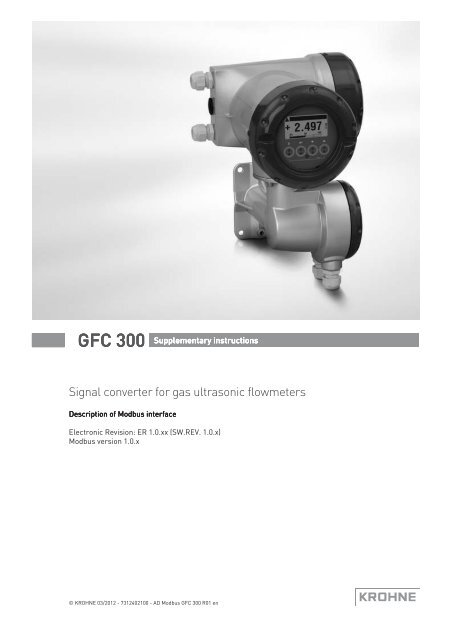
<strong>GFC</strong> <strong>300</strong> Supplementary instructions<br />
Signal converter for gas ultrasonic flowmeters<br />
Description of Modbus interface<br />
Electronic Revision: ER 1.0.xx (SW.REV. 1.0.x)<br />
Modbus version 1.0.x<br />
© KROHNE 03/2012 - 7312402100 - AD Modbus <strong>GFC</strong> <strong>300</strong> R01 en
CONTENTS<br />
<strong>GFC</strong> <strong>300</strong><br />
1 Important information 3<br />
2 Technical data 4<br />
2.1 General technical data .....................................................................................................4<br />
2.2 Technical data of the Modbus interface (acc. to EIA standards) ..................................... 4<br />
3 Connection in bus systems 5<br />
4 Local configuration 6<br />
5 Electrical connection 7<br />
6 Modbus protocol 9<br />
6.1 General information concerning the protocol ................................................................. 9<br />
6.2 RTU frame format............................................................................................................. 9<br />
6.3 Addressing...................................................................................................................... 10<br />
6.4 Overview of supported functions.................................................................................... 10<br />
6.5 Device identification on the Modbus interface............................................................... 11<br />
6.6 Coil registers .................................................................................................................. 11<br />
6.6.1 Converter controls ................................................................................................................ 11<br />
6.6.2 Counter controls ................................................................................................................... 12<br />
6.6.3 Start calibration functions .................................................................................................... 12<br />
6.7 Input registers ................................................................................................................ 12<br />
6.8 Holding registers............................................................................................................ 14<br />
6.8.1 Counter parameters ............................................................................................................. 15<br />
6.8.2 Process input parameters .................................................................................................... 16<br />
6.8.3 Modbus parameters.............................................................................................................. 17<br />
6.9 Diagnostics ..................................................................................................................... 17<br />
7 Notes 18<br />
2 www.krohne.com 03/2012 - 7312402100 - AD Modbus <strong>GFC</strong> <strong>300</strong> R01 en
<strong>GFC</strong> <strong>300</strong><br />
IMPORTANT INFORMATION 1<br />
The flow converter with the RS485 interface card fitted, is able to communicate with an external<br />
device (PC or other suitable computer system) using the Modbus protocol. This option allows<br />
data exchange between PC or computer and single or multiple devices.<br />
The bus configuration consists of one external device as a master and one or more converters as<br />
slaves. For bus operation the device address (menu C5.8.1), baudrate (menu C5.8.2) and settings<br />
(menu C5.8.3, C5.8.4, C5.8.5 & C5.8.6) must be set in the converter.<br />
All devices connected to the bus, must have different unique addresses but the same baud rate<br />
and settings.<br />
03/2012 - 7312402100 - AD Modbus <strong>GFC</strong> <strong>300</strong> R01 en<br />
www.krohne.com<br />
3
2 TECHNICAL DATA<br />
<strong>GFC</strong> <strong>300</strong><br />
2.1 General technical data<br />
Interface<br />
RS485, galvanically isolated<br />
Baud rate 1200, 2400, 3600, 4800, 9600, 19200, 38400, 57600 or 115200<br />
Protocol<br />
Maximum participants on bus<br />
Coding<br />
Modbus RTU (available as a separate document on request)<br />
32 per line, master included (may be extended by repeaters)<br />
NRZ bit coding<br />
Address range Modbus: 1...247<br />
Transmission procedure<br />
Bus access<br />
Cable<br />
Distances<br />
Half duplex, asynchronous<br />
Master / slave<br />
Shielded twisted pair for RS 485 applications<br />
Maximum 1.2 km / 3937 ft without repeater (dependant on<br />
baud rate and cable specifications)<br />
2.2 Technical data of the Modbus interface (acc. to EIA standards)<br />
Kind of signal transmission<br />
Maximum number of<br />
transmitter/receivers<br />
Voltage range on converter input<br />
Maximum voltage on converter output<br />
Minimum voltage on driver output, max.<br />
load<br />
Maximum input current (off state)<br />
Receiver input voltage<br />
Sensitivity of the receiver<br />
Receiver input resistance<br />
Short circuit current<br />
Termination / polarization resistors<br />
(if activated by the jumpers X5/X6)<br />
Differential, 2-wire topology<br />
32<br />
-7...+12 V<br />
5V<br />
U diff >1.5V<br />
-20...+20 μA<br />
-7...+12 V<br />
-200...+200 mV<br />
>12kΩ<br />
< 250 mA<br />
120 Ω / 560 Ω<br />
4<br />
www.krohne.com<br />
03/2012 - 7312402100 - AD Modbus <strong>GFC</strong> <strong>300</strong> R01 en
<strong>GFC</strong> <strong>300</strong><br />
CONNECTION IN BUS SYSTEMS 3<br />
For proper operation of Modbus in half duplex mode in single or multi-drop communication, it is<br />
recommended that a termination resistor is applied to both ends of the data line. The simplest<br />
form of termination is line-to-line resistor across the differential input.<br />
In RTU mode the Modus protocol requires quiet periods on the communications bus for<br />
synchronisation. It is therefore important that the Modbus is not allowed to "float", i.e.<br />
unreferenced to 0 V, as this could lead to spurious signals due to noise pick-up. It is therefore<br />
necessary to employ biasing resistors at one point on the bus network, normally the "end".<br />
The Modbus converter has two conditions. Default is without termination and polarization. To get<br />
the active termination and polarization the settings of jumper X5 and X6 on Modbus board must<br />
be changed. This can only be done by qualified personnel. For detailed information, refer to<br />
Electrical connection on page 7.<br />
03/2012 - 7312402100 - AD Modbus <strong>GFC</strong> <strong>300</strong> R01 en<br />
www.krohne.com<br />
5
4 LOCAL CONFIGURATION<br />
<strong>GFC</strong> <strong>300</strong><br />
Converter Fct.<br />
No.<br />
Display<br />
Description and settings<br />
C5.8.1 Slave Address Selects the Modbus address of the device.<br />
Range: 1..247 (default = 1)<br />
C5.8.2 Baud Rate Selects the baud rate of the device.<br />
Options:<br />
1200 / 2400 / 3600 / 4800 / 9600 / 19200 (default) / 38400 / 57600 / 115200<br />
C5.8.3 Parity Selects the parity.<br />
Options:<br />
Even (default) / Odd / No<br />
C5.8.4 Data Format Selects the data format.<br />
Options:<br />
Big Endian (default) / Little Endian<br />
C5.8.5 Transmission Delay Selects the delay between receiving the last byte of a request and<br />
sending the first byte of the response.<br />
Range: 0..40ms (default = 0ms)<br />
C5.8.6 Stop Bits Selects the number of stop bits.<br />
Options:<br />
1 (default) / 2<br />
C5.8.7 Information Displays information about the device.<br />
6<br />
www.krohne.com<br />
03/2012 - 7312402100 - AD Modbus <strong>GFC</strong> <strong>300</strong> R01 en
<strong>GFC</strong> <strong>300</strong><br />
ELECTRICAL CONNECTION 5<br />
Terminals A and B of the converter are dependant on the options selected at order. Refer to the<br />
standard handbook of the converter for connection details.<br />
Figure 5-1: Location of I/O connector<br />
Figure 5-2: Modbus connection<br />
1 Master device<br />
2 Shielded twisted pair cable<br />
3 Slave device = <strong>GFC</strong> <strong>300</strong><br />
Modbus connections<br />
Terminals<br />
Description<br />
D- Signal A (D 0)<br />
D Signal B (D 1)<br />
C- Common (shield)<br />
C<br />
Not connected<br />
03/2012 - 7312402100 - AD Modbus <strong>GFC</strong> <strong>300</strong> R01 en<br />
www.krohne.com<br />
7
5 ELECTRICAL CONNECTION<br />
<strong>GFC</strong> <strong>300</strong><br />
CAUTION!<br />
Underneath instructions are for qualified personnel only!<br />
Jumper settings on the Modbus printed circuit board<br />
Jumper position<br />
Description<br />
X5 X6<br />
1-2 1-2 With termination and polarization<br />
2-3 2-3 Without termination and polarization<br />
8<br />
www.krohne.com<br />
03/2012 - 7312402100 - AD Modbus <strong>GFC</strong> <strong>300</strong> R01 en
<strong>GFC</strong> <strong>300</strong><br />
MODBUS PROTOCOL 6<br />
6.1 General information concerning the protocol<br />
Using RTU (Remote Terminal Unit) format, data is transmitted as 8 bit binary characters. There<br />
are no special characters to determine the start and end of a message frame.<br />
Synchronization is achieved by a minimum silent period of at least 3.5 character times before the<br />
start of each frame transmission and a maximum silent period of 1.5 character times between<br />
characters in the same frame.<br />
6.2 RTU frame format<br />
The format of the query and response frames vary slightly depending upon the command<br />
function. The basic form is outlined below.<br />
Command function Frame format Description<br />
Silent period 3.5 x T All transmissions must be preceded by a minimum silent<br />
period of 3.5 x T, where T is the transmission time of a<br />
single character. This can be calculated from the baud<br />
rate, e.g. at 19.2 kb no parity with 1 stop bit (10 bits),<br />
T=520µs.<br />
Slave address 8bits This is a single byte slave address which is transmitted<br />
first and must be in the range of 1...247. Address 0 is<br />
reserved for a broadcast address which all slaves should<br />
recognize, and therefore requires no response.<br />
Function code 8bits This is an eight bit code in the range of 1...255 although<br />
only 126 functions exist as the codes 129...255 represent<br />
an error condition. An error condition occurs when the<br />
addressed slave does not accept the command, in which<br />
case it responds with the function code + 128, i.e. with its<br />
MSB set to 1.<br />
Register start address or<br />
byte count when required<br />
8 bit byte count<br />
16 bit address<br />
Register start address: for a query command that requires<br />
data to be returned, this field will contain the 16 bit start<br />
address of the register (or data) to be returned.<br />
Note that the converter uses protocol addresses.<br />
Therefore the register address listed is the actual number<br />
required in the Modbus command.<br />
E.g: to access input register <strong>300</strong>06, the register start<br />
address is <strong>300</strong>06dec = 7536hex.<br />
Number of points or data<br />
bytes when required<br />
n×8bits<br />
Byte count: In general this is only present in frames that<br />
are transferring data, and has a value equal to the number<br />
of bytes contained in the data field. The data field is limited<br />
to a maximum of 250 bytes.<br />
Number of points: for a query command that requires data<br />
to be returned, this field will contain the number of<br />
registers to be returned regardless of their bit size.<br />
Data bytes: contains the data requested. The converter can<br />
use big endian format (MSB first) or little endian<br />
format (LSB first).<br />
CRC 16 bits This field contains a 16 bit CRC which is calculated on all<br />
the data bits of the message bytes.<br />
03/2012 - 7312402100 - AD Modbus <strong>GFC</strong> <strong>300</strong> R01 en<br />
www.krohne.com<br />
9
6 MODBUS PROTOCOL<br />
<strong>GFC</strong> <strong>300</strong><br />
6.3 Addressing<br />
In the following tables the Modbus protocol addresses / data addresses are listed.<br />
Some systems cannot use addresses above 9999. For these systems there is the possibility to<br />
use the listed addresses but<br />
• for Input Registers omit the leading 3 of 3xxxx;<br />
• for Holding Registers omit the leading 4 of 4xxxx;<br />
• for Input Registers replace the leading 20 of 20xxx by 9xxx.<br />
Sometimes register numbers are asked for. The register numbers can be calculated by adding a<br />
1 to the protocol address and using a prefix according to the block:<br />
• prefix 1 for coils<br />
• prefix 3 for Input Registers<br />
• prefix 4 for Holding Registers<br />
6.4 Overview of supported functions<br />
The following table shows Modbus functions supported by RS485 interface.<br />
Function code Name Access to<br />
hex dec<br />
01 01 Read Coil Status of calibration functions (not applicable)<br />
Counter status (start/stop)<br />
03 03 Read Holding Register Acyclic Registers<br />
04 04 Read Input Register Cyclic Register<br />
05 05 Write Single Coil Cold start<br />
Warm start<br />
Error reset<br />
Start calibration function (not applicable)<br />
Start / stop counter<br />
08 08 Diagnostics -<br />
10 16 Write Multiple Register Acyclic Registers<br />
2B 43 Encapsulated Interface Transport Transparent Channel<br />
Read Device Identification<br />
10<br />
www.krohne.com<br />
03/2012 - 7312402100 - AD Modbus <strong>GFC</strong> <strong>300</strong> R01 en
<strong>GFC</strong> <strong>300</strong><br />
MODBUS PROTOCOL 6<br />
6.5 Device identification on the Modbus interface<br />
The device identification is according to the category "Regular" according to the Modbus<br />
Application Protocol Specification V1.1a. Function code 43 / 14 (0x2B / 0x0E).<br />
Modbus<br />
object Id<br />
Object name / Description Type GDC Object<br />
Number<br />
Content<br />
0x00 VendorName 16 Byte ASCII<br />
ASCII String<br />
0x01 ProductCode 10 Byte ASCII String 32519.32<br />
(24731.32)<br />
6.6 Coil registers<br />
These function codes are used for access:<br />
• 0x01 = read input coil<br />
• 0x05 = write single coil<br />
24730.32 KROHNE<br />
CG number (order code for the<br />
converter assembly)<br />
0x02 MajorMinorRevision 7 Byte ASCII String 24732.32 V1.1.xx<br />
0x03 Vendor URL 32 Byte ASCII String 24733.32 www.krohne.com<br />
0x04 ProductName 16 Byte ASCII String 24734.32 <strong>GFC</strong> <strong>300</strong><br />
0x05 ModelName 16 Byte ASCII String 24735.32 Modbus<br />
0x06 UserApplicationName 16 Byte ASCII String 24736.32 User tag, displayed on the header<br />
of the local screen<br />
6.6.1 Converter controls<br />
Coil address<br />
Function<br />
1000 Write 1 generates a cold start, write 0 is ignored<br />
1001 Write 1 generates a warm start, write 0 is ignored<br />
1002 Write 1 generates an error reset, write 0 is ignored<br />
03/2012 - 7312402100 - AD Modbus <strong>GFC</strong> <strong>300</strong> R01 en<br />
www.krohne.com<br />
11
6 MODBUS PROTOCOL<br />
<strong>GFC</strong> <strong>300</strong><br />
6.6.2 Counter controls<br />
Modbus protocol<br />
address<br />
Description Settings Converter Fct. No.<br />
<strong>300</strong>0 Start / Stop Write 1 start counter C3.1.8 / C3.1.9<br />
Counter 1<br />
Write 0 stop counter<br />
Read 1 counter is running<br />
Read 0 counter is stopped<br />
<strong>300</strong>1 Start / Stop Write 1 start counter C3.2.8 / C3.2.9<br />
Counter 2<br />
Write 0 stop counter<br />
Read 1 counter is running<br />
Read 0 counter is stopped<br />
<strong>300</strong>2 Start / Stop Write 1 start counter C3.3.8 / C3.3.9<br />
Counter 3 1<br />
Write 0 stop counter<br />
Read 1 counter is running<br />
Read 0 counter is stopped<br />
<strong>300</strong>3 Reset Counter 1 Write 1 reset counter C3.1.6<br />
Write 0 -<br />
Read 0 -<br />
<strong>300</strong>4 Reset Counter 2 Write 1 reset counter C3.2.6<br />
Write 0 -<br />
Read 0 -<br />
<strong>300</strong>5 Reset Counter 3 1 Write 1 reset counter C3.3.6<br />
Write 0 -<br />
Read 0 -<br />
1 Only available in converters with IO2. A write attempt to a non-existing counter will cause an error response.<br />
6.6.3 Start calibration functions<br />
No calibration functions have been foreseen in the Modbus Interface.<br />
6.7 Input registers<br />
Measurement and status values are read only and can be accessed as Modbus "Input Registers".<br />
Function code is 04 (0x04).<br />
Input register (3)0018 is not used for the gas option. This address has been included to have the<br />
same layout of the higher addresses of cyclic values.<br />
12<br />
www.krohne.com<br />
03/2012 - 7312402100 - AD Modbus <strong>GFC</strong> <strong>300</strong> R01 en
<strong>GFC</strong> <strong>300</strong><br />
MODBUS PROTOCOL 6<br />
Modbus protocol<br />
address<br />
Description and settings Type Number of registers<br />
1st<br />
2nd<br />
<strong>300</strong>00 0 Volume flow float 2<br />
<strong>300</strong>02 2 Corrected volume flow (gas only) float 2<br />
Enthalpy flow (steam only)<br />
<strong>300</strong>04 4 Mass flow float 2<br />
<strong>300</strong>06 6 Molar mass (gas only) float 2<br />
Specific enthalpy (steam only)<br />
<strong>300</strong>08 8 Not used, returns zero (gas only) float 2<br />
Density (steam only)<br />
<strong>300</strong>10 10 Flow speed float 2<br />
<strong>300</strong>12 12 Velocity of sound float 2<br />
<strong>300</strong>14 14 Gain float 2<br />
<strong>300</strong>16 16 Diagnostics 1<br />
float 2<br />
value 2436.32<br />
1 = none<br />
2 = velocity of sound 1<br />
3 = gain 1<br />
4 = SNR 1<br />
<strong>300</strong>18 18 Diagnostics 2<br />
float 2<br />
value 2437.32<br />
1 = none<br />
2 = velocity of sound 2<br />
3 = gain 2<br />
4 = SNR 2<br />
<strong>300</strong>20 20 Diagnostics 3<br />
float 2<br />
value 2438.32<br />
1 = none<br />
2 = velocity of sound 3<br />
3 = gain 3<br />
4 = SNR 3<br />
<strong>300</strong>22 22 Temperature of the medium<br />
float 2<br />
(only with appropriate Current Input)<br />
<strong>300</strong>24 24 Pressure of the medium<br />
float 2<br />
(only with appropriate Current Input)<br />
<strong>300</strong>26 26 Operating time float 2<br />
<strong>300</strong>28 28 counter 1 double float 4<br />
<strong>300</strong>32 32 Counter 2 double float 4<br />
<strong>300</strong>36 36 Counter 3 (IO2 only) double float 4<br />
<strong>300</strong>40 40 Long status sensor byte [4] 2<br />
<strong>300</strong>42 42 Long status device byte [4] 2<br />
03/2012 - 7312402100 - AD Modbus <strong>GFC</strong> <strong>300</strong> R01 en<br />
www.krohne.com<br />
13
6 MODBUS PROTOCOL<br />
<strong>GFC</strong> <strong>300</strong><br />
6.8 Holding registers<br />
All holding registers in the Modbus protocol address range from 40000 to 49998 are mapped into<br />
the range 0 to 9998. This is done to give systems with restriction on the address range access to<br />
the device.<br />
Some parameters of the device can be accessed as Modbus "holding registers".<br />
Function code 03 (0x03) for "Read" operations and function code 16 (0x10) for "Write" operations.<br />
The holding registers are grouped into the following different sections.<br />
14<br />
www.krohne.com<br />
03/2012 - 7312402100 - AD Modbus <strong>GFC</strong> <strong>300</strong> R01 en
<strong>GFC</strong> <strong>300</strong><br />
MODBUS PROTOCOL 6<br />
6.8.1 Counter parameters<br />
INFORMATION!<br />
Counter 3 parameters are only available for converter with IO 2.<br />
Modbus protocol<br />
address<br />
Description and settings<br />
Converter Fct.<br />
No.<br />
Type<br />
Number of<br />
registers<br />
1st<br />
2nd<br />
40000 0 Counter 1 function<br />
1=sum counter<br />
C3.1.1 byte 1<br />
2=+counter<br />
3 = - counter<br />
0=off<br />
40001 1 Measurement Cnt1<br />
20 = volume flow<br />
C3.1.2 word 1<br />
21 = corr. volume (gas only)<br />
21 = enthalpy flow (steam only)<br />
22 = mass flow<br />
40002 2 Counter 2 function<br />
C3.2.1 byte 1<br />
1=sum counter<br />
2=+counter<br />
3 = - counter<br />
0=off<br />
40003 3 Measurement Cnt2<br />
20 = volume flow<br />
C3.2.2 word 1<br />
21 = corr. volume flow (gas only)<br />
21 = enthalpy flow (steam only)<br />
22 = mass flow<br />
40004 4 Counter 3 function<br />
1=sum counter<br />
C3.3.1 byte 1<br />
2=+counter<br />
3 = - counter<br />
0=off<br />
40005 5 Measurement Cnt3<br />
20 = Volume flow<br />
C3.3.2 word 1<br />
21 = corr. volume flow (gas only)<br />
21 = enthalpy flow (steam only)<br />
22 = mass flow<br />
41000 1000 Low flow cutoff value Cnt1 C3.1.3 float 2<br />
41002 1002 Time constant Cnt1 C3.1.4 float 2<br />
41004 1004 Set counter Cnt1 or read Cnt1 C3.1.7 float 2<br />
41006 1006 Low flow cutoff value Cnt2 C3.2.3 float 2<br />
41008 1008 Time constant Cnt2 C3.2.4 float 2<br />
41010 1010 Set counter Cnt2 or read Cnt2 C3.2.7 float 2<br />
41012 1012 Low flow cutoff value Cnt3 C3.3.3 float 2<br />
41014 1014 Time constant Cnt3 C3.3.4 float 2<br />
41016 1016 Set counter Cnt3 or read Cnt3 C3.3.7 float 2<br />
41018 1018 Preset counter 1 C3.1.5 float 2<br />
41020 1020 Preset counter 2 C3.2.5 float 2<br />
41022 1022 Preset counter 3 C3.3.5 float 2<br />
03/2012 - 7312402100 - AD Modbus <strong>GFC</strong> <strong>300</strong> R01 en<br />
www.krohne.com<br />
15
6 MODBUS PROTOCOL<br />
<strong>GFC</strong> <strong>300</strong><br />
6.8.2 Process input parameters<br />
Modbus protocol<br />
address<br />
Description and settings<br />
Converter Fct.<br />
No.<br />
Type<br />
Number of<br />
registers<br />
1st<br />
2nd<br />
42000 2000 Meter size C1.1 float 2<br />
42002 2002 GK C1.2.2 float 2<br />
42004 2004 Limitation min C1.3.1 float 2<br />
42006 2006 Limitation max C1.3.1 float 2<br />
42008 2008 Flow direction C1.3.2 byte 1<br />
42009 2009 Time constant C1.3.3 float 2<br />
42011 2011 Low flow cutoff threshold C1.3.4 float 2<br />
42013 2013 Low flow cutoff hysterese C1.3.4 float 2<br />
42015 2015 Plausibility error limit C1.4.1 float 2<br />
42017 2017 Plausibility counter decrease C1.4.2 integer 1<br />
42018 2018 Plausibility counter limit C1.4.3 integer 1<br />
42019 2019 VoS monitor function (steam only) C1.7 byte 1<br />
42020 2020 Matching factor (steam only) C1.8.1 float 2<br />
42022 2022 VoS tolerance (steam only) C1.8.4 float 2<br />
42024 2024 VoS time constant (steam only) C1.8.5 float 2<br />
42026 2026 Linearization C1.9.1 byte 1<br />
42027 2027 Dynamic viscosity (gas only) C1.9.2 float 2<br />
42029 2029 Adiabatic index (gas only) C1.10 float 2<br />
42031 2031 P&T correction (gas only)<br />
0 = off<br />
C1.11 byte 1<br />
1 = normal<br />
42032 2032 P&T inputs (gas only) C1.12 byte 1<br />
42033 2033 Pipe temperature (gas only) C1.13 float 2<br />
42035 2035 Pipe pressure (gas only) C1.14 float 2<br />
42037 2037 Density (gas only) C1.15 float 2<br />
42039 2039 Option diagnosis 1:<br />
1 = none<br />
C1.16.1 byte 1<br />
2 = velocity of sound 1<br />
3 = gain 1<br />
4 = SNR 1<br />
42040 2040 Option diagnosis 2:<br />
1 = none<br />
C1.16.2 byte 1<br />
2 = velocity of sound 2<br />
3 = gain 2<br />
4 = SNR 2<br />
42041 2041 Option diagnosis 3:<br />
1 = none<br />
2 = velocity of sound 3<br />
3 = gain 3<br />
4 = SNR 3<br />
6 = SNR<br />
C1.16.3 byte 1<br />
16<br />
www.krohne.com<br />
03/2012 - 7312402100 - AD Modbus <strong>GFC</strong> <strong>300</strong> R01 en
<strong>GFC</strong> <strong>300</strong><br />
MODBUS PROTOCOL 6<br />
6.8.3 Modbus parameters<br />
Modbus protocol<br />
address<br />
Description and settings<br />
50000 Baud rate<br />
1200 / 2400 / 3600 / 4800 / 9600 / 19200<br />
(default) / 38400 / 57600 / 115200<br />
50002 Slave address<br />
1 = default<br />
range = 1...247<br />
50003 Parity<br />
0 = even parity (default)<br />
1 = odd parity<br />
3=no parity<br />
50004 Data format<br />
0 = Little Endian<br />
1 = Big Endian (default)<br />
50005 Transmission delay<br />
0 ms (default)<br />
range = 0...40 ms<br />
50007 Stop bits<br />
1 = 1 stop bit (default)<br />
2 = 2 stop bits<br />
Converter Fct.<br />
No.<br />
Type<br />
C5.8.2 ulong 2<br />
C5.8.1 byte 1<br />
C5.8.3 byte 1<br />
C5.8.4 byte 1<br />
C5.8.5 float 2<br />
C5.8.6 byte 1<br />
Number of<br />
registers<br />
6.9 Diagnostics<br />
The Modbus interface supports the diagnostic function defined by the "Modbus Application<br />
Protocol Specification".<br />
Function code is 08 (0x08).<br />
Sub function code<br />
Name<br />
hex dec<br />
00 00 Return Query Data<br />
01 01 Restart Communication Option<br />
04 04 Force Listen Only Mode<br />
0A 10 Clear Counters<br />
0B 11 Return Bus Message Count<br />
0C 12 Return Bus Communication Error Count<br />
0D 13 Return Bus Exception Count<br />
0E 14 Return Slave Message Count<br />
0F 15 Return Slave No Response Count<br />
10 16 Return Slave NAK Count (counter not used)<br />
11 17 Return Slave Busy Count (counter not used)<br />
12 18 Return Bus Character Overrun Count<br />
03/2012 - 7312402100 - AD Modbus <strong>GFC</strong> <strong>300</strong> R01 en<br />
www.krohne.com<br />
17
7 NOTES<br />
<strong>GFC</strong> <strong>300</strong><br />
18<br />
www.krohne.com<br />
03/2012 - 7312402100 - AD Modbus <strong>GFC</strong> <strong>300</strong> R01 en
<strong>GFC</strong> <strong>300</strong><br />
NOTES 7<br />
03/2012 - 7312402100 - AD Modbus <strong>GFC</strong> <strong>300</strong> R01 en<br />
www.krohne.com<br />
19
KROHNE product overview<br />
© KROHNE 03/2012 - 7312402100 - AD Modbus <strong>GFC</strong> <strong>300</strong> R01 en - Subject to change without notice.<br />
• Electromagnetic flowmeters<br />
• Variable area flowmeters<br />
• Ultrasonic flowmeters<br />
• Mass flowmeters<br />
• Vortex flowmeters<br />
• Flow controllers<br />
• Level meters<br />
• Temperature meters<br />
• Pressure meters<br />
• Analysis products<br />
• Products and systems for the oil & gas industry<br />
• Measuring systems for the marine industry<br />
Head Office KROHNE Messtechnik GmbH<br />
Ludwig-Krohne-Str. 5<br />
47058 Duisburg (Germany)<br />
Tel.:+49 (0)203 301 0<br />
Fax:+49 (0)203 301 10389<br />
info@krohne.de<br />
The current list of all KROHNE contacts and addresses can be found at:<br />
www.krohne.com


