Intel® NetStructure™ 6000 Switch
Intel® NetStructure™ 6000 Switch
Intel® NetStructure™ 6000 Switch

You also want an ePaper? Increase the reach of your titles
YUMPU automatically turns print PDFs into web optimized ePapers that Google loves.
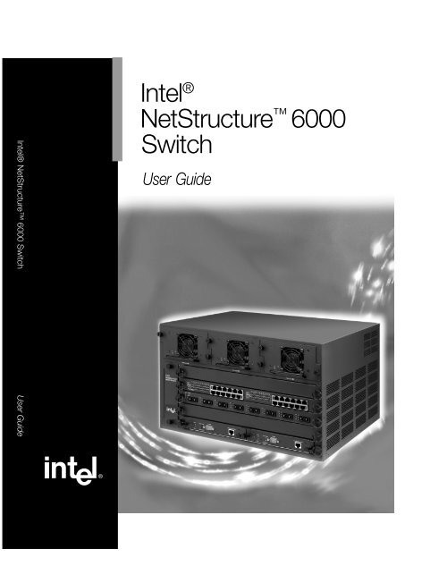
<strong>Intel®</strong> NetStructure <strong>6000</strong> <strong>Switch</strong> User Guide<br />
Intel ®<br />
NetStructure <strong>6000</strong><br />
<strong>Switch</strong><br />
User Guide
Copyright © 2000, Intel Corporation. All rights reserved.<br />
Intel Corporation, 5200 NE Elam Young Parkway, Hillsboro OR 97124-6497<br />
Information in this document is provided in connection with <strong>Intel®</strong> products. No license, express or<br />
implied, by estoppel or otherwise, to any intellectual property rights is granted by this document. Except as<br />
provided in Intel's Terms and Conditions of Sale for such products, Intel assumes no liability whatsoever,<br />
and Intel disclaims any express or implied warranty, relating to sale and/or use of <strong>Intel®</strong> products including<br />
liability or warranties relating to fitness for a particular purpose, merchantability, or infringement of any<br />
patent, copyright or other intellectual property right. Intel products are not intended for use in medical, life<br />
saving, or life sustaining applications. Intel may make changes to specifications and product descriptions at<br />
any time, without notice.<br />
*Other product and corporate names may be trademarks of other companies and are used only for explanation and to the<br />
owners’ benefit, without intent to infringe.<br />
First Edition May 2000 A19070-001
Contents<br />
Using the <strong>Switch</strong> 5<br />
Unpacking the <strong>Switch</strong> .................................................. 6<br />
Overview ..................................................................... 7<br />
Assessing the Installation Site ................................... 13<br />
Attaching Rack Mount Brackets................................. 13<br />
Setting Up the Chassis .............................................. 14<br />
Troubleshooting ......................................................... 22<br />
Equipment Replacement............................................ 23<br />
Using <strong>Intel®</strong> Device View 31<br />
Overview .................................................................... 32<br />
Installing Intel Device View ........................................ 32<br />
Starting Intel Device View .......................................... 34<br />
Installing a New Device.............................................. 35<br />
Using the Device Tree ............................................... 36<br />
Managing a <strong>Switch</strong>..................................................... 38<br />
Viewing RMON information........................................ 39<br />
Using the Web Device Manager 41<br />
Accessing the Web Device Manager ......................... 43<br />
Navigating the Web Device Manager ........................ 44<br />
View/Configure Device Menu..................................... 50<br />
Configure Management Menu ................................... 66<br />
VLAN Menu................................................................ 74<br />
Routing Menu........................................................... 100<br />
Reset and Update Menu .......................................... 114<br />
Help Menu................................................................ 119
Contents<br />
<strong>Intel®</strong> NetStructure <strong>6000</strong> <strong>Switch</strong> User Guide<br />
Using Local Management 121<br />
Connecting the <strong>Switch</strong>.............................................. 122<br />
The RS-232 Port ...................................................... 123<br />
The RJ-45 Management Port ................................... 126<br />
Setting a Password .................................................. 127<br />
Setting the IP Address.............................................. 130<br />
BOOTP/RARP and DHCP Client ............................. 131<br />
BOOTP Relay Agent ................................................ 133<br />
Command Console Interface.................................... 134<br />
Accessing the Command Console through Telnet ... 136<br />
Serial Line IP Connections (SLIP)............................ 137<br />
Point-to-Point Protocol (PPP)................................... 138<br />
Domain Name Service ............................................. 140<br />
Diagnostics............................................................... 142<br />
Upgrading the Firmware........................................... 143<br />
Managing the <strong>Switch</strong> 145<br />
Layer 2 <strong>Switch</strong>ing ..................................................... 146<br />
Link Aggregation ...................................................... 146<br />
Aggregated Port Numbers........................................ 155<br />
Virtual LANs (VLANs)............................................... 156<br />
Spanning Tree Protocol............................................ 166<br />
IGMP Snooping ........................................................ 172<br />
Port Mirroring............................................................ 176<br />
Layer 2 Frame Prioritization ..................................... 177<br />
SNMP Agent............................................................. 178<br />
RMON ...................................................................... 182<br />
NVRAM Backup ....................................................... 182<br />
SYSLOG................................................................... 184<br />
2<br />
2
Contents<br />
<strong>Intel®</strong> NetStructure <strong>6000</strong> <strong>Switch</strong> User Guide<br />
Broadcast and Multicast Storm Control ................... 185<br />
Layer 3 <strong>Switch</strong>ing & Routing.................................... 187<br />
IP Access Control .................................................... 187<br />
Routing Management............................................... 192<br />
GateD....................................................................... 194<br />
Appendix A: Command Reference 211<br />
Appendix B: GateD Reference 305<br />
Interfaces ................................................................. 306<br />
Adding Static Routes ............................................... 308<br />
RIP Configuration..................................................... 309<br />
RIP Interface Configuration...................................... 310<br />
OSPF Configuration................................................. 311<br />
Configuring ASE Routes .......................................... 312<br />
Configuring the Backbone........................................ 313<br />
Configuring OSPF Interfaces ................................... 314<br />
Virtual Links ............................................................. 315<br />
OSPF Neighbor Table.............................................. 317<br />
OSPF Area Link State Advertisement Database ..... 321<br />
Route Table ............................................................. 322<br />
Appendix C: Technical Information 325<br />
Support Services...................................................... 326<br />
Regulatory Information............................................. 329<br />
Limited Hardware Warranty ..................................... 330<br />
Index 333<br />
3<br />
3
Using the <strong>Switch</strong><br />
Topic<br />
See Page<br />
Unpacking the <strong>Switch</strong> 6<br />
Overview 7<br />
Assessing the Installation Site 13<br />
Attaching Rack Mount Brackets 13<br />
Setting Up the Chassis 14<br />
Front Panel LEDs 21<br />
Troubleshooting 22<br />
Equipment Replacement 23
C H A P T E R 1<br />
<strong>Intel®</strong> NetStructure <strong>6000</strong> <strong>Switch</strong> User Guide<br />
Unpacking the <strong>Switch</strong><br />
The chassis shipping carton contains the following items:<br />
• <strong>Intel®</strong> NetStructure <strong>6000</strong> <strong>Switch</strong> chassis, with the fan assembly,<br />
one power supply and four AC power cords.<br />
• Carrier Tray<br />
• Control Processor (CP)<br />
• Null modem cable for RS-232 Port<br />
• Rack mount kit<br />
• A pouch that includes<br />
-Rubber adhesive-backed feet<br />
-Product registration card<br />
-The <strong>Intel®</strong> NetStructure <strong>6000</strong> <strong>Switch</strong> Quick Start<br />
-The <strong>Intel®</strong> NetStructure <strong>6000</strong> <strong>Switch</strong> User Guide for the<br />
Gigabit and Fast Ethernet Modules<br />
-The <strong>Intel®</strong> NetStructure <strong>6000</strong> <strong>Switch</strong> User Guide<br />
-Late-breaking News<br />
-The <strong>Intel®</strong> Device View CD-ROM.<br />
Separate cartons include: an optional CP module, and, Gigabit<br />
Ethernet and Fast Ethernet modules that were ordered.<br />
Note<br />
Do not unpack the modules until you are ready to install<br />
them in the chassis.<br />
• Additional power supplies with AC power cords, if purchased.<br />
(Each power supply is shipped in a separate carton.)<br />
6
C H A P T E R 1<br />
Using the <strong>Switch</strong><br />
Overview<br />
AC POWER CONNECTION BACK<br />
POWER SUPPLIES<br />
MODULES<br />
RS-232 PORT<br />
FAN ASSESMBLY<br />
CONTROL PROCESSORS<br />
10/100 ETHERNET (RJ-45) PORT<br />
The chassis has five module slots. The bottom slot is reserved for the<br />
carrier tray which holds the primary and optional secondary control<br />
processors (CPs). The other slots may contain up to four I/O modules,<br />
which can be placed in any of the remaining slots. The table below<br />
describes the available modules.<br />
I/O Modules<br />
Available<br />
Modules<br />
per<br />
Chassis<br />
Available<br />
Ports per<br />
Chassis<br />
Features per<br />
Slot<br />
1000Base-SX<br />
<strong>Switch</strong> Module<br />
4 32 Eight-port<br />
full-duplex<br />
switched<br />
Gigabit<br />
Ethernet<br />
module<br />
7
C H A P T E R 1<br />
<strong>Intel®</strong> NetStructure <strong>6000</strong> <strong>Switch</strong> User Guide<br />
I/O Modules<br />
Available<br />
Modules<br />
per<br />
Chassis<br />
Available<br />
Ports per<br />
Chassis<br />
Features per<br />
Slot<br />
1000Base-LX/<br />
1000Base-SX<br />
<strong>Switch</strong> Module<br />
10/100Base-TX<br />
<strong>Switch</strong> Module<br />
100Base-FX<br />
Module<br />
Control<br />
Processor<br />
4 32 Eight-port<br />
full-duplex<br />
switch Gigabit<br />
Ethernet<br />
module with<br />
four LX and<br />
four SX ports.<br />
4 96 100Base-TX<br />
Ethernet<br />
module<br />
containing 24<br />
switched RJ-<br />
45 ports.<br />
4 48 100Base-FX<br />
Ethernet<br />
module<br />
containing 12<br />
SC Fiber<br />
Optic<br />
connectors.<br />
2 N/A Each contains<br />
one RS-232<br />
(DB9)<br />
connector and<br />
one RJ-45 10/<br />
100 Ethernet<br />
management<br />
port.<br />
Each module and each CP has Light Emitting Diodes (LEDs) which<br />
are used to designate various board status. See the <strong>Intel®</strong><br />
NetStructure <strong>6000</strong> <strong>Switch</strong> User Guide for the Gigabit and Fast<br />
Ethernet Modules for detailed information on the LEDs for each<br />
module.<br />
8
C H A P T E R 1<br />
Using the <strong>Switch</strong><br />
The chassis also includes the cooling system which is made up of a<br />
series of three fans. The three fans are contained in a single fan<br />
module. The fan module is hot swappable and can be easily replaced.<br />
See “Fan Assembly Replacement” for instructions on replacing a fan<br />
assembly.<br />
Warning<br />
Only fan assembly modules identified as “Hot Swappable<br />
Fan” on the front of the chassis can be replaced<br />
without powering down the switch.<br />
The power supply system consists of up to three individually<br />
replaceable power modules.<br />
Note<br />
Dual power supplies are recommended for proper operation<br />
of four media modules.<br />
In order to implement a redundant power supply system, any two of<br />
the three possible power supplies can be used to power the system. In<br />
the case where redundancy is required, the supplies load balance.<br />
Should one power supply fail, the other assumes the entire load.<br />
Each power supply module may be replaced without turning off<br />
power to the switch. See “Installing Power Supplies” for instructions<br />
on replacing a power supply.<br />
Redundant Control Processors<br />
The CP module occupies one half of the control processor slot. Using<br />
two CP boards, creates a redundant CP system. This allows the switch<br />
to support hot standby CP board that takes over should the first CP<br />
board fail during normal operation. (In addition, the crossbar logic is<br />
duplicated on each CP board, eliminating single points of failure<br />
within the chassis.)<br />
Each CP board contains a high-speed crossbar for moving data<br />
between boards connected to the backplane.<br />
An RS-232 port is included for connection to a remote terminal or<br />
modem. A 10/100 Ethernet management port is also included for outof-band<br />
management and firmware upgrades. This Ethernet port is<br />
not part of the switching fabric.<br />
9
C H A P T E R 1<br />
<strong>Intel®</strong> NetStructure <strong>6000</strong> <strong>Switch</strong> User Guide<br />
Fault Tolerance<br />
The switch has a fault tolerant design to reduce network downtime<br />
with redundant fans, load-sharing power supplies, hot-swappable I/O<br />
and power modules. Non-volatile RAM (NVRAM) is available for<br />
backup and restoration of system parameters. See Chapter 5 for<br />
instructions on using the NVRAM backup commands.<br />
<strong>Switch</strong> Management<br />
Command line vs. Web browser<br />
The switch is managed using a command-line interface or using a<br />
Web browser.<br />
• Command Line Interface<br />
The CP module supports a command-line interface through the serial<br />
port or via Telent through the 10/100 management port. The<br />
command-line interface enables local or remote unit installation and<br />
maintenance. A set of system commands allows effective monitoring,<br />
configuration and debugging of the device. See “Accessing the<br />
Command Console Interface” in Chapter 4 for more information<br />
about the management features.<br />
• Web Device Manager<br />
The Web Device Manager provides access to the switch’s<br />
configuration, administration and statistics through a Web browser.<br />
See Chapter 3 for details.<br />
Layer 2 <strong>Switch</strong>ing<br />
Layer 2 switching moves packets through the switching fabric based<br />
upon the destination MAC address of the packet. The switch supports<br />
wire-speed Layer 2 switching for all network protocols.<br />
The functionality of the Layer 2 switching operates in the context of<br />
a single switched network segment. Multiple Virtual LAN (VLAN)<br />
operation and switching within a VLAN are discussed in Chapter 3<br />
and Chapter 5.<br />
10
C H A P T E R 1<br />
Using the <strong>Switch</strong><br />
Layer 3 <strong>Switch</strong>ing<br />
Layer 3 switching performs a function similar to Layer 2 switching,<br />
except it looks at the network layer information rather than the<br />
destination MAC address. To improve the usability of the switch, it<br />
uses routing protocols to communicate existing routes to hosts and to<br />
coordinate route information with other routing devices.<br />
The routing capability must be considered for all network layer<br />
protocols supported by the switch. For each network layer protocol<br />
one or more routing protocols may be invoked. For the Internet<br />
Protocol (IPv4), these protocols are RIP v1, RIP v2, and OSPF.<br />
The functionality of Layer 3 switching relies upon the use of VLANs<br />
to define network segments. Routing occurs between the network<br />
segments. VLAN operation is discussed in Chapter 3 and Chapter 5.<br />
Link Aggregation<br />
The <strong>6000</strong> switch supports the 802.3ad draft link aggregation<br />
specification. Link Aggregation allows two or more physical ports on<br />
the switch to be grouped together to provide a single, aggregated port<br />
that has the combined bandwidth of the individual ports. Link<br />
Aggregation is useful when making connections between switches,<br />
stacks or to connect servers to the switch.An added benefit of Link<br />
Aggregation is increased performance, increased resiliency and fault<br />
tolerance. See Chapter 3 and Chapter 5 for instructions on<br />
configuring Link Aggregation.<br />
Virtual LANs<br />
Virtual LAN (VLAN) capability allows for the grouping of ports<br />
together into logical groups. Any port can be assigned to one or more<br />
virtual LANs, allowing effective reconfiguration without physically<br />
moving cables. The switch limits forwarding database (FDB) misses<br />
and broadcast and multicast traffic within a VLAN. The switch<br />
conforms to the IEEE 802.1Q definition of a VLAN aware bridge in<br />
a virtual bridge local area network. See Chapter 3 and Chapter 5 for<br />
instructions on setting up VLANs.<br />
11
C H A P T E R 1<br />
<strong>Intel®</strong> NetStructure <strong>6000</strong> <strong>Switch</strong> User Guide<br />
Spanning Tree Protocol<br />
The <strong>6000</strong> switch supports multilayer Spanning Trees.The IEEE<br />
802.1D specification Spanning Tree Protocol allows switches or<br />
bridges to eliminate duplicate paths and loops in a network. However,<br />
the Spanning Tree Protocol must be operational on other bridges and<br />
switches throughout the network. The switch also supports 802.1s, a<br />
supplement to 802.1Q, that provides for multiple instances of<br />
Spanning Tree to run on a switch that has multiple VLANS. Each<br />
VLAN acts as a separate bridge or virtual bridge.<br />
See Chapter 3 and Chapter 5 for more information on setting up the<br />
Spanning Tree Protocol.<br />
Built-in SNMP<br />
The switch supports standard management approaches, including<br />
SNMP, out-of-band management through an RS-232 console port or<br />
modem, and through a TELNET session. An extensive set of<br />
supported SNMP Management Information Bases (MIBs) includes:<br />
• MIB II (RFC 1213)<br />
• Four-group RMON 1 (RFC 1757)<br />
• Etherlike MIB (STD50)<br />
• RIP version 2 MIB (RFC 1724l)<br />
• Bridge MIB (RFC 1493),<br />
• Q-Bridge MIB<br />
• OSPF MIB (RFC 1850)<br />
• Link Aggregation MIB (802.3ad)<br />
• IP Forwarding Table MIB (RFC 2096)<br />
• <strong>Intel®</strong> proprietary MIB<br />
See Chapter 5 for information on the SMNP agent commands.<br />
12
C H A P T E R 1<br />
Using the <strong>Switch</strong><br />
Assessing the Installation Site<br />
To operate the switch, the site should have the following facilities:<br />
• Power source to supply 6.0 A @ 125V, 60 Hz, or 3.0 A @ 250V,<br />
50 Hz, for each switch.<br />
• Operating environment temperature between 0º and 40º C<br />
(32º F to 104º F).<br />
• Allow at least four inches (4") of space surrounding the switch to<br />
provide for proper ventilation.<br />
• Do not exceed humidity levels at 90% non-condensing.<br />
The switch may be placed on a desk or table top, or it may be mounted<br />
in a standard 19" equipment rack. Apply the adhesive-backed rubber<br />
feet to the bottom of the switch if the switch is placed on a flat<br />
surface.<br />
Attaching Rack Mount<br />
Brackets<br />
To mount the chassis in an equipment rack, attach the rack mount<br />
brackets provided.<br />
Front Panel Screws<br />
1 Remove the four front-most screws on each side of the unit, as<br />
shown in the figure above.<br />
2 Fasten the brackets using the screws provided.<br />
13
C H A P T E R 1<br />
<strong>Intel®</strong> NetStructure <strong>6000</strong> <strong>Switch</strong> User Guide<br />
3 After the brackets are securely fastened, the switch can be<br />
mounted into a standard (19") equipment rack.<br />
Caution<br />
Fully assembled, the switch weighs over 90 pounds.<br />
Mount the chassis prior to installing any modules or<br />
power supplies. Always use two people to lift the<br />
switch.<br />
Setting Up the Chassis<br />
Follow the instructions below to install the Carrier tray, CP, modules<br />
and any additional power supplies that were ordered.<br />
Assembled Chassis<br />
AC POWER CONNECTION BACK<br />
POWER SUPPLIES<br />
MODULES<br />
RS-232 PORT<br />
FAN ASSESMBLY<br />
CONTROL PROCESSORS<br />
10/100 ETHERNET (RJ-45) PORT<br />
14
C H A P T E R 1<br />
Using the <strong>Switch</strong><br />
Installing the Carrier Tray<br />
1 Remove the Carrier tray from the chassis carton.<br />
2 Carefully remove the Carrier tray from the ESD protective bag<br />
and place it on a flat surface.<br />
3 Lift the tray up by placing your hands on the sides of the tray or<br />
underneath the tray.<br />
4 Carefully slide the tray into the bottom slot of the Chassis (Slot<br />
5).<br />
5 Push the tray back until it connects with the backplane.<br />
Warning The backplane pins are easily bent. Use caution when<br />
inserting the carrier tray to insure proper alignment.<br />
6 Tighten both capture panel screws simultaneously.<br />
Carrier Tray Installation<br />
Slot 5<br />
Gender<br />
Adapter Bar<br />
Carrier Tray<br />
15
C H A P T E R 1<br />
<strong>Intel®</strong> NetStructure <strong>6000</strong> <strong>Switch</strong> User Guide<br />
Installing the Control Processor<br />
Modules<br />
1 Remove the CP from the protective foam and caps.<br />
2 Carefully remove the CP from the ESD protective bag and place<br />
it on a flat surface.<br />
Warning Electrostatic Sensitive Device. Do not handle the<br />
printed circuit board unless the working area is static<br />
free!.<br />
Control Processor Installation<br />
Slot 5<br />
Primary CP<br />
3 Lift the board up by placing both hands on the side of the module<br />
faceplate panel or underneath the tray.<br />
4 Carefully slide the module into the left side of the Carrier tray.<br />
5 Push the module back until it connects with the gender adapter<br />
bar on the Carrier tray and the capture panel screws engage the<br />
chassis.<br />
16
C H A P T E R 1<br />
Using the <strong>Switch</strong><br />
6 Tighten both capture panel screws simultaneously.<br />
7 If a secondary CP was ordered, repeat steps 1 through 6 and<br />
place the card on the right side of the Carrier tray.<br />
Control Processor Module<br />
Carrier Ready LED<br />
Status LED<br />
RS-232 Port<br />
Faceplate Panel<br />
Capture<br />
Panel<br />
Screw<br />
Diagnostics LED<br />
10/100 Ethernet Port (RJ-45)<br />
Primary/Secondary LED<br />
Note<br />
If the primary CP fails during boot up on a dual CP system,<br />
the secondary CP will not become the primary CP for at<br />
least five minutes. When both CPs boot successfully, the<br />
secondary CP assumes control within sixty-five seconds<br />
after the master CP fails.<br />
Installing Other Modules<br />
The Gigabit Ethernet and Fast Ethernet module may be placed in any<br />
of the four remaining slots.<br />
1 Remove the module from the modules’ carton.<br />
2 Carefully remove the module from the ESD protective bag and<br />
place it on a flat surface.<br />
Warning Electrostatic Sensitive Device. Do not handle the<br />
printed circuit board unless the working area is static<br />
free!<br />
3 Lift the board up by placing both hands on the side of the module<br />
faceplate panel or underneath the tray.<br />
4 Remove the blank filler tray from any of the slot bays.<br />
17
C H A P T E R 1<br />
<strong>Intel®</strong> NetStructure <strong>6000</strong> <strong>Switch</strong> User Guide<br />
5 Carefully slide the module into the empty slot.<br />
6 Push the module back until it connects with the backplane and<br />
the capture panel screws engage the chassis.<br />
Warning The backplane pins are easily bent. Use caution when<br />
inserting the module to insure proper alignment.<br />
7 Tighten both capture panel screws simultaneously.<br />
Module Installation<br />
Gigabit<br />
Ethernet<br />
Module<br />
Caution<br />
Always place one of the spare blank filler plates in the<br />
unused slots. This helps to maintain proper air flow<br />
throughout the chassis and keeps it free from dust.<br />
18
C H A P T E R 1<br />
Using the <strong>Switch</strong><br />
Installing Power Supplies<br />
If an additional power supply has been purchased, place it in any of<br />
the empty power supply bays at the top of the chassis.<br />
Note Intel recommends that for proper operation, you install an<br />
additional power supply if there are four media boards.<br />
1 Unpack the power supply from the carton.<br />
2 Loosen the capture panel screws on the face plate of the power<br />
supply bay until the face plate can be removed.<br />
3 Using the handle, pick up the power supply with one hand and<br />
support it underneath with the other hand.<br />
.<br />
Power Supply Installation<br />
Capture Panel<br />
Screws<br />
4 Push the power supply into the power supply bay until the capture<br />
panel screws engage the chassis.<br />
5 Tighten the capture panel screws simultaneously.<br />
19
C H A P T E R 1<br />
<strong>Intel®</strong> NetStructure <strong>6000</strong> <strong>Switch</strong> User Guide<br />
Connecting the Power Cords<br />
1 Attach a power cord to each installed power supply.<br />
2 Plug the other end of each power cord into a properly protected<br />
AC power source.<br />
Once power is supplied, the switch automatically detects and powers<br />
up the modules found in each slot.<br />
Back Panel<br />
Checking Physical Condition<br />
Carefully review the switch installation instructions. Also complete<br />
the following physical examination of the switch and its cables:<br />
1 Check the switch for physical damage.<br />
2 Make sure the cables are installed according to instructions.<br />
3 Make sure all connections are secure and complete.<br />
4 Check the cables for possible crimps or excessive wear that may<br />
cause electrical short or incomplete connections.<br />
20
C H A P T E R 1<br />
Using the <strong>Switch</strong><br />
Front Panel LEDs<br />
Check the Control Processor (CP) front panel indicators (LEDs).<br />
LED Color Definition<br />
Status Solid Yellow Power up self-test<br />
running.<br />
Flashing Yellow<br />
Flashing Green<br />
Solid Green<br />
Power up diagnostics<br />
failed.<br />
Normal Operation - the<br />
CP module is operating<br />
normally and the media<br />
boards have completed<br />
their power up cycle.<br />
Boot image mode.<br />
Diagnostic Solid Yellow Running built-in selftest<br />
(BIST) sequence.<br />
Solid Green<br />
Passed built-in selftest<br />
(BIST) sequence.<br />
Carrier Ready Solid Green Carrier Board is<br />
operating.<br />
Primary/<br />
Secondary<br />
Solid Yellow<br />
Solid Green<br />
Solid Yellow<br />
Carrier Board has<br />
failed.<br />
Designates the active<br />
CP.<br />
Designates the standby<br />
CP (requires two CP<br />
modules).<br />
• The Status LED on the CP board should light solid yellow while<br />
the built-in self-test (BIST) sequence is run.<br />
• The Status LED changes to flashing green if no errors are<br />
detected.<br />
21
C H A P T E R 1<br />
<strong>Intel®</strong> NetStructure <strong>6000</strong> <strong>Switch</strong> User Guide<br />
• The Status LED changes to flashing yellow if an error condition<br />
is detected.<br />
• The Status LED maintains a solid green light if the switch boots<br />
up in boot image mode instead of the system image. See the<br />
Troubleshooting section to diagnose if there is a problem.<br />
Also check the Power Supply LEDs to ensure the power supplies are<br />
functioning properly.<br />
LED Color Definition<br />
AC Solid Yellow AC input power present.<br />
DC Solid Green Normal Operation - the<br />
power supply is operating<br />
normally. DC output is<br />
present.<br />
See the <strong>Intel®</strong> NetStructure <strong>6000</strong> <strong>Switch</strong> User Guide for the<br />
Gigabit and Fast Ethernet Modules for a description of the module<br />
LEDs.<br />
After completing the initial setup and power up, connect the switch to<br />
the network, set passwords for non-privileged and privileged mode,<br />
and assign an IP address to the switch. See Chapter 4 for details.<br />
Troubleshooting<br />
If the switch fails to operate, determine if there is a physical problem<br />
or a problem with the configuration of the switch to the network. This<br />
section gives you a quick guide to troubleshooting these problems.<br />
Troubleshooting Checklist<br />
Review the symptoms shown below for possible causes and<br />
recommended courses of action when the switch does not function as<br />
expected.<br />
22
C H A P T E R 1<br />
Using the <strong>Switch</strong><br />
Symptom Possible Cause Course of Action<br />
No indicators lighted. Power cord is loose. Check power cord<br />
connections.<br />
CP slot OK but other<br />
slots have no<br />
indicator lights<br />
CP LED display is<br />
solid green.<br />
Failure reported in<br />
one or more<br />
diagnostic tests.<br />
Power supply is<br />
faulty.<br />
Module has failed<br />
three times in a row.<br />
Bad board<br />
Power supply faulty<br />
Incompatible<br />
firmware version.<br />
Processor is in boot<br />
image mode instead<br />
of system image<br />
mode.<br />
Internal hardware is<br />
faulty.<br />
Refer to “Power<br />
Supply Replacement”<br />
for instructions on<br />
diagnosing power<br />
supply problems and<br />
replacing a power<br />
supply.<br />
Use show sysfails<br />
command to detect<br />
failed module.<br />
Use show sysfails<br />
command to detect<br />
failed module or<br />
power supply.<br />
Use show version<br />
command to detect<br />
firmware version.<br />
Reload firmware<br />
from Intel Web site.<br />
Contact Customer<br />
Support.<br />
Equipment Replacement<br />
Fan Assembly Replacement<br />
A fan failure can cause the chassis temperature to rise above<br />
acceptable levels. You are automatically notified on the console when<br />
a fan has failed.<br />
23
C H A P T E R 1<br />
<strong>Intel®</strong> NetStructure <strong>6000</strong> <strong>Switch</strong> User Guide<br />
Type the non-privileged show sysfails command at the command line<br />
to display which of the three fans has failed.<br />
<strong>6000</strong> <strong>Switch</strong>>#>show sysfails<br />
Fan Failure at Tue 6/8/99 12:59<br />
Fan 2 had failed, and is still failing.<br />
Note If the maximum operating temperature does not exceed 40º<br />
C (104º F), the switch continues to operate for the periods<br />
described in the following table Type show temperature at<br />
the command line to view the current switch temperature.<br />
Number of Failed Fans Shut-down Time<br />
1 None<br />
2 12 hours<br />
3 1 hour<br />
The following messages warn of impending shutdowns.<br />
• Trigger: temperature sensor has reached 44º C<br />
Warning: The switch temperature has reached 44º C. Automatic<br />
shutdown will occur at 48º C.<br />
In Intel Device View, this is a yellow warning alert. This message is<br />
sent every five minutes until the temperature drops below 44º C or<br />
reaches 46º C.<br />
• Trigger: temperature sensor has reached 46º C.<br />
Critical Warning: The switch has reached 46º C. Automatic<br />
shutdown will occur at 48º C.<br />
In Intel Device View, this is a yellow warning alert. This message is<br />
sent every minute until the temperature drops below 46º C or reaches<br />
47º C.<br />
• Trigger: temperature sensor has reached 47º C.<br />
Critical Warning: The switch temperature has reached 47º C.<br />
Automatic shutdown will occur at 48º C.<br />
In Intel Device View, this is a red warning alert. This message is sent<br />
every one minute until the temperature drops below 47º C or reaches<br />
48º C.<br />
24
C H A P T E R 1<br />
Using the <strong>Switch</strong><br />
• Trigger: temperature sensor has reached 48º C<br />
Critical Warning: The switch temperature has reached 47º C.<br />
Automatic shutdown has commenced.<br />
In Intel Device View, this is a red warning alert.<br />
• Trigger: temperature sensor has reached 44, 46 or 47º C and then<br />
has dropped back to 43º C.<br />
Critical Warning: The switch temperature has dropped below<br />
critical limits. The temperature is now 43º C.<br />
In Intel Device View, this is a green alert.<br />
When one or two fans have failed, the warning messages are:<br />
• Trigger: temperature sensor has reached 38º C<br />
Critical Warning: The switch has reached 38C. Automatic<br />
shutdown will occur at 40º C.<br />
In Intel Device View, this is a red warning alert. This message is sent<br />
every minute until the temperature drops below 38º C.<br />
• Trigger: temperature sensor has reached 39º C<br />
Critical Warning: The switch has reached 39ºC. Automatic<br />
shutdown will occur at 40º C.<br />
In Intel Device View, this is a red warning alert. This message is sent<br />
every minute until the temperature drops below 38º C.<br />
To replace the fan assembly<br />
Warning Only fan assembly modules identified as “Hot Swappable<br />
Fan” on the front of the chassis can be replaced<br />
without powering down the switch.<br />
1 Locate the fan assembly on the front panel of the chassis.<br />
2 Unscrew the capture panel screws on the fan assembly panel.<br />
3 Grasp the fan assembly with both hands and carefully pull it out<br />
from the backplane.<br />
25
C H A P T E R 1<br />
<strong>Intel®</strong> NetStructure <strong>6000</strong> <strong>Switch</strong> User Guide<br />
Hot Swa pable Fan<br />
Capture<br />
Panel<br />
Screw<br />
Hot Swappable Fan label<br />
Fan Assembly<br />
Fan Assembly Panel<br />
4 Lift the fan assembly and place it safely on a flat surface.<br />
5 Unpack the replacement fan assembly.<br />
6 Slide the replacement fan assembly back until the capture panel<br />
screws engage the chassis.<br />
7 Tighten the capture panel screws.<br />
8 Reattach the power cords to the rear of the chassis.<br />
9 Type the non-privileged command clear sysfails after replacing<br />
a power supply to reset the show sysfails command.<br />
<strong>6000</strong> <strong>Switch</strong>>#>clear sysfails<br />
The system failure area has been cleared.<br />
26
C H A P T E R 1<br />
Using the <strong>Switch</strong><br />
Power Supply Replacement<br />
A loss or reduction of power causes a full or partial shutdown of the<br />
switch.<br />
Type the show sysfails command at the terminal to determine which<br />
of the power supplies has failed.<br />
Type the non-privileged command clear sysfails after replacing a<br />
power supply to reset the show sysfails command.<br />
<strong>6000</strong> <strong>Switch</strong>>#>clear sysfails<br />
The system failure area has been cleared.<br />
Caution<br />
If the switch has two power supplies, place the replacement<br />
in the empty power-supply bay before removing<br />
one of the power supplies. This prevents the switch<br />
from powering down during hot swap of the power supplies.<br />
Power Supply<br />
Capture Panel<br />
To replace a power supply<br />
1 Loosen the capture panel screws on the front of the power supply.<br />
2 Using the handle, pull out the power supply with one hand and<br />
27
C H A P T E R 1<br />
<strong>Intel®</strong> NetStructure <strong>6000</strong> <strong>Switch</strong> User Guide<br />
grab it underneath with the other hand.<br />
3 Place the power supply on a flat surface.<br />
4 Unpack the replacement power supply.<br />
5 Place one hand on the handle and the other hand underneath to<br />
lift the power supply.<br />
6 Carefully slide the power supply into the power supply bay.<br />
7 Tighten the capture panel screws simultaneously.<br />
8 If returning the power supply, pack the original power supply in<br />
the materials provided for the replacement power supply.<br />
Note If a power supply bay is to remain empty, be sure to install<br />
the blank power supply face plate provided. This protects<br />
the chassis from dust.<br />
Replacing a Control Processor Module<br />
1 Remove the Control Processor from the carton.<br />
2 Carefully remove the Control Processor from the ESD protective<br />
bag and place it on a flat surface.<br />
Warning Electrostatic Sensitive Device. Do not handle the<br />
printed circuit board unless the working area is static<br />
free!.<br />
Secondary Control Processor Installation<br />
Secondary CP<br />
28
C H A P T E R 1<br />
Using the <strong>Switch</strong><br />
3 Lift the board up by placing both hands on the side of the module<br />
faceplate panel or underneath the tray.<br />
4 Carefully slide the module into the empty side of the Carrier<br />
tray.<br />
5 Push the module back until it connects with the gender adapter<br />
bar and the capture panel screws engage the chassis.<br />
6 Tighten both capture panel screws simultaneously.<br />
Note<br />
If the primary Control Processor fail to boot up on a dual<br />
Control Processor system, the secondary Control Processor<br />
will not become the primary Control Processor for at least<br />
five minutes. When both Control Processors boot successfully,<br />
the secondary CP assumes control within sixty-five<br />
seconds after the master CP fails.<br />
Replacing Modules<br />
Gigabit<br />
Ethernet<br />
Module<br />
1 Disconnect the network interface cables from the module ports.<br />
2 Loosen the capture panel screws on either side of the module<br />
face plate.<br />
29
C H A P T E R 1<br />
<strong>Intel®</strong> NetStructure <strong>6000</strong> <strong>Switch</strong> User Guide<br />
3 Pull the module out, away from the backplane.<br />
Warning Electrostatic Sensitive Device. Do not handle the<br />
printed circuit board unless the working area is static<br />
free!<br />
4 Place the module on a flat surface until you have removed the<br />
replacement module from the packing materials.<br />
5 Remove the replacement module from the ESD protective bag.<br />
6 Lift the module up by placing your hands on either side of the<br />
module face plate panel. Again, be careful not to touch the circuit<br />
area.<br />
7 Carefully slide the module into the slot.<br />
8 Push the module back until the capture panel screws engage the<br />
chassis.<br />
9 Tighten both capture panel screws simultaneously.<br />
10 Pack the original module in the materials provided for the<br />
replacement module.<br />
The modules are hot swappable. Removing and inserting a module<br />
does not reset the switch.<br />
When a module is inserted or removed, the following message is<br />
displayed on the console, and the status LED on the CPU remains<br />
solid green.<br />
<strong>6000</strong> <strong>Switch</strong>><br />
Configuring system: Do not remove any media modules.<br />
Preparing for hot swap: OK<br />
Warning<br />
Do not insert or remove another medial module until<br />
the Status LED is flashing green. The system resets if<br />
the Status LED is not flashing.<br />
The following message is displayed if a module is removed or<br />
inserted before the Status LED has changed to flashing green:<br />
**************************************************<br />
* Media removal/failure during configuration update<br />
* Resetting system...<br />
**************************************************<br />
30
Using <strong>Intel®</strong><br />
Device View<br />
Topic<br />
See Page<br />
Overview 32<br />
Installing <strong>Intel®</strong> Device View 32<br />
Starting <strong>Intel®</strong> Device View 34<br />
Installing a New Device 35<br />
Using the Device Tree 36<br />
Managing a <strong>Switch</strong> 38<br />
Viewing RMON Information 39
C H A P T E R 2<br />
<strong>Intel®</strong> NetStructure <strong>6000</strong> <strong>Switch</strong> User Guide<br />
Overview<br />
<strong>Intel®</strong> Device View, versions 2.1.6 or later, lets you manage the<br />
<strong>Intel®</strong> NetStructure <strong>6000</strong> <strong>Switch</strong> and other supported Intel<br />
networking devices on your network.<br />
Intel Device View provides these features:<br />
• The ability to configure new network devices<br />
• Graphical device manager for Intel switches, hubs, and routers<br />
• Autodiscovery, which finds supported Intel devices on the network<br />
• The Device Tree, which shows all the supported devices detected on<br />
your network<br />
• Remote Network Monitoring (RMON)<br />
• Web or Windows* platform<br />
• Plug-in to HP OpenView*, IBM Tivoli NetView*, and Intel<br />
LANDesk® Network Manager.<br />
• Other useful tools such as a TFTP server, Telnet and Ping.<br />
Installing Intel Device View<br />
Before you install Intel Device View, make sure your PC meets the<br />
system requirements in the <strong>Intel®</strong> Device View User Guide, which is<br />
included on the Intel Device View CD-ROM.<br />
32
C H A P T E R 2<br />
Using <strong>Intel®</strong> Device View<br />
To install Intel Device View<br />
1 Put the Intel Device View CD-ROM in your computer’s CD-ROM<br />
drive. The Intel Device View installation screen appears. If it does<br />
not appear, run autoplay.exe from the CD-ROM.<br />
2 Choose the version of Intel Device View you want to install.<br />
• Click Install for Windows to install Intel Device View for<br />
use on this PC only.<br />
• Click Install for Web to install Intel Device View on a Web<br />
server. You will be able to access the Device View server<br />
from any PC on your network with Internet Explorer 4.0x or<br />
later.<br />
• Click Install as Plug-in to install Intel network device support<br />
for HP OpenView, IBM Tivoli NetView, or Intel LANDesk<br />
Network Manager. This option is not available if you don’t have<br />
OpenView, LANDesk Network Manager, or NetView installed<br />
on the PC.3<br />
3 Follow the instructions on screen in the installation program.<br />
33
C H A P T E R 2<br />
<strong>Intel®</strong> NetStructure <strong>6000</strong> <strong>Switch</strong> User Guide<br />
Starting Intel Device View<br />
Install either the Windows or Web version of Intel Device View.<br />
Windows* version<br />
If you manage devices with Intel Device View from only one location<br />
on the network, install the Windows version. From your desktop,<br />
click Start, then point to Programs > Intel Device View > Intel<br />
Device View - Windows. Intel Device View’s main screen appears.<br />
Web version<br />
If you want to manage devices from any PC on the network using<br />
Intel Device View, install the Web version.<br />
• From your desktop, click Start, then point to Programs > Intel<br />
Device View > Intel Device View - Web. Intel Device View’s main<br />
screen appears.<br />
• To view Intel Device View from another PC on your network, type<br />
the following URL, http://servername/devview/main.htm, where<br />
servername is the IP address or name of the server where Intel<br />
Device View is installed. In the example shown below, the URL is<br />
entered into the Address field in Internet Explorer.<br />
Intel Device View’s main screen appears.<br />
34
C H A P T E R 2<br />
Using <strong>Intel®</strong> Device View<br />
Installing a New Device<br />
After you’ve installed a new switch on your network, you can use<br />
Intel Device View’s Device Install Wizard to configure it for<br />
management.<br />
To install and configure a new switch for<br />
management<br />
1 Start Intel Device View. The Device Install Wizard appears. If it<br />
does not appear, click Install from the Device menu or doubleclick<br />
the appropriate MAC address in the Device Tree under<br />
Unconfigured Devices.<br />
2 In the Device Install Wizard - Start screen, click Next.<br />
3 In the Device Install Wizard - MAC Address screen, click the<br />
MAC address of the new switch, then click Next.<br />
4 Follow the instructions in the wizard to assign an IP address and a<br />
name to the switch.<br />
35
C H A P T E R 2<br />
<strong>Intel®</strong> NetStructure <strong>6000</strong> <strong>Switch</strong> User Guide<br />
Using the Device Tree<br />
When you start Intel Device View, the Device Discovery service<br />
begins searching for supported Intel network devices on your<br />
network. As it discovers devices, the Device Discovery service adds<br />
an icon for each device to the Device Tree on the left side of the<br />
screen. Different states of the <strong>6000</strong> <strong>Switch</strong> are represented by unique<br />
icons in the Device Tree.<br />
Device Tree icons<br />
Device Tree root<br />
Subnet<br />
Intel NetStructure <strong>Switch</strong><br />
(non-responding the icon is red)<br />
Unconfigured Intel NetStructure <strong>Switch</strong><br />
Group of Intel NetStructure <strong>Switch</strong>es<br />
Intel NetStructure <strong>Switch</strong> (Layer 3 capable)<br />
36
C H A P T E R 2<br />
Using <strong>Intel®</strong> Device View<br />
The Device Tree works much like Windows Explorer. To expand the<br />
root or a subnet, click the (+) next to the icon. To collapse the view,<br />
click the (-) next to the icon. Double-click a device icon to view the<br />
device image.<br />
To add a device to the Device Tree<br />
1 Right-click anywhere on the Device Tree.<br />
2 Click Add Device on the menu that appears.<br />
3 In the Add Device dialog box, type the IP address of the switch you<br />
want to add.<br />
4 Fill in the other fields, as appropriate.<br />
5 Click OK.<br />
The new switch’s icon appears in the Device Tree.<br />
To refresh the Device Tree<br />
1 Right-click anywhere on the Device Tree.<br />
2 Click Refresh on the menu that appears.<br />
Refreshing the Device Tree updates it to show any newly discovered<br />
devices and changes in device status.<br />
To delete a device from the Device Tree<br />
1 Right-click the device you want to remove from the Device Tree.<br />
2 Click Delete on the menu that appears.<br />
Deleting a device from the Device Tree does not affect the actual<br />
device.<br />
To find a device in the Device Tree<br />
1 Right-click anywhere on the Device Tree.<br />
2 Click Find on the menu that appears.<br />
3 In the Find Device dialog box, type the IP address of the device<br />
you want to find in the tree.<br />
4 Click OK.<br />
The device’s icon is highlighted in the Device Tree.<br />
37
C H A P T E R 2<br />
<strong>Intel®</strong> NetStructure <strong>6000</strong> <strong>Switch</strong> User Guide<br />
Losing contact with a device<br />
If Intel Device View loses contact with a switch, it replaces the switch<br />
icon with the non-responding switch icon. When the non-responding<br />
switch icon appears, you will not be able to manage the device in Intel<br />
Device View. If you’re unable to ping the device or start a Telnet<br />
session, try accessing the switch’s Local Management.<br />
Managing a <strong>Switch</strong><br />
To manage a <strong>6000</strong> switch, double-click the switch icon in the Device<br />
Tree. In the example shown below, the switch has been assigned an<br />
IP address of 124.123.122.3.<br />
38
C H A P T E R 2<br />
Using <strong>Intel®</strong> Device View<br />
The <strong>6000</strong> switch’s Web Device Manager appears in the Intel Device<br />
View window. Use the Web Device Manager as described in Chapter<br />
3.<br />
For complete information on using Intel Device View, refer to the<br />
program’s on-line help or see the User Guide on the Intel Device<br />
View installation CD-ROM.<br />
Viewing RMON information<br />
The remote monitoring (RMON) specification extends SNMP<br />
functionality to look at traffic patterns on the network instead of<br />
merely looking at the traffic for an individual device. The following<br />
RMON groups are supported:<br />
• Group 1 (Statistics): Monitors utilization and error statistics for<br />
each network segment (10 Mbps or 100 Mbps).<br />
• Group 2 (History): Records periodic statistical samples from<br />
variables available in the statistics group.<br />
39
C H A P T E R 2<br />
<strong>Intel®</strong> NetStructure <strong>6000</strong> <strong>Switch</strong> User Guide<br />
• Group 3 (Alarms): Allows you to set a sampling interval and alarm<br />
thresholds for statistics. When a threshold is passed, the switch<br />
creates an event. For example, you might set an alarm if switch<br />
utilization exceeds 30%.<br />
• Group 9 (Events): Provides notification and tells the switch what to<br />
do when an event occurs on the network. Events can send a trap to a<br />
trap receiving station or place an entry in the log table, or both. For<br />
example, when the switch experiences an RMON Event, it sends out<br />
an Alarm. The switch also keeps a log that shows a list of the<br />
RMON Events and RMON Alarms that have occurred on the switch.<br />
To view RMON statistics<br />
1 Right-click the switch’s icon in the Device Tree, then point to<br />
RMON.<br />
2 Click the RMON option you want to view:<br />
You can also access RMON features by using LANDesk Network<br />
Manager, or an SNMP application that supports RMON such as<br />
OpenView. For more information about using RMON to monitor the<br />
switch, refer to the Intel Device View Help.<br />
40
Using the Web<br />
Device Manager<br />
Topic<br />
See Page<br />
Accessing the Web Device Manager 43<br />
Navigating the Web Device Manager 44<br />
View/Configure Device Menu 50<br />
Configure Management Menu 66<br />
VLAN Menu 74<br />
Routing Menu 100<br />
Reset and Update Menu 114<br />
Help Menu 119
C H A P T E R 3<br />
<strong>Intel®</strong> NetStructure <strong>6000</strong> <strong>Switch</strong> User Guide<br />
The Web Device Manager is built into the <strong>Intel®</strong> NetStructure<br />
<strong>6000</strong> <strong>Switch</strong>, and it lets you use a Web browser to manage and<br />
monitor the switch. For example, you can use the Web Device<br />
Manager to configure the switch or individual ports, to monitor traffic<br />
statistics and utilization and to view and configure switch devices,<br />
Virtual LANs (VLANs) and routing.<br />
Note<br />
If accessing the Web Device Manager through a serial or<br />
terminal connection, always make the connection through<br />
the management port instead of a media board port.<br />
The Web Device Manager can be used with the following frame<br />
capable browsers: Microsoft Internet Explorer*, versions 4.05 or<br />
later and Netscape Navigator*, versions 4.0 or later. The monitor<br />
display resolution should be set at 1024 x 768 pixels for best results.<br />
If you are using Microsoft Internet Explorer 4.0 or later, configure the<br />
browser to check for newer versions of stored pages each time you<br />
load the page.<br />
42
C H A P T E R 3<br />
Using the Web Device Manager<br />
If you are using Netscape 4.0 or higher, configure the browser to<br />
compare cached documents to documents on the network every time.<br />
Note The top-level menu is normally collapsed until you rightclick<br />
to expand the menu items. Some older versions of<br />
Netscape browsers are incompatible and limit the mechanism<br />
for keeping track of open menu items. The Web<br />
Device Manager detects these incompatible browsers and<br />
expands all menu items.<br />
The menus do not collapse with Netscape for Solaris*, version<br />
4.04 and Netscape for Linux*, version 4.05<br />
Netscape for Solaris, version 4.5 and Netscape for Linux,<br />
version 4.61 are compatible.<br />
For additional information about using this interface, see Web Device<br />
Manager Help.<br />
Accessing the Web Device<br />
Manager<br />
1 Type the switch’s IP address in your Web browsers’ address or<br />
location field.<br />
2 Click OK. The password dialog box is displayed.<br />
43
C H A P T E R 3<br />
<strong>Intel®</strong> NetStructure <strong>6000</strong> <strong>Switch</strong> User Guide<br />
3 Type in the default username priv.<br />
4 The switch is shipped with a “null” password (i.e., no password).<br />
Press OK to access the Web Device Manager. If you<br />
have not set a basic or privileged password, refer to the Configure<br />
Management menu later in this chapter for instructions on<br />
setting a password.<br />
If you have set a password, type the current privileged password<br />
for the switch, then click OK. The Web interface recognizes the<br />
password that was set at the console command line.<br />
Note If the basic password is used to login to the switch, you cannot<br />
configure or set features on the switch until you have<br />
logged in with the privileged password.<br />
5 In the menu on the left, select options to configure and access<br />
the various administrative areas of the switch configuration.<br />
Navigating the Web Device<br />
Manager<br />
1 Click a menu (such as View/Configure Device) on the left side<br />
of the Web Device Manager window to show options.<br />
2 Click an option in the menu. The corresponding screen appears<br />
on the right side of your Web browser window.<br />
44
C H A P T E R 3<br />
Using the Web Device Manager<br />
45
C H A P T E R 3<br />
<strong>Intel®</strong> NetStructure <strong>6000</strong> <strong>Switch</strong> User Guide<br />
Display Options<br />
Hypertext links are displayed in many of the tables. Click the link to<br />
access configuration screens for the selected option.<br />
The table below describes the colors used to display port connection<br />
information.<br />
Port Color<br />
Gray<br />
Green<br />
Orange Cross<br />
10/100 & Gigabit Ethernet<br />
Link Down<br />
Link Up<br />
Disabled Port<br />
Use the browser’s View menu font options to change the text size and<br />
display more data in the main frame.<br />
46
C H A P T E R 3<br />
Using the Web Device Manager<br />
Buttons<br />
Each configuration screen includes various buttons on the bottom of<br />
the screen.<br />
Button<br />
Submit<br />
Reset<br />
Apply<br />
Default<br />
Help<br />
Function<br />
Applies the configuration settings on the current<br />
screen. Saves the settings to NVRAM.<br />
Clears any changes you made on the current<br />
screen and restores the currently applied<br />
settings.<br />
Saves the current configuration.<br />
Resets the current screen to the factory default<br />
settings.<br />
Displays help for current screen.<br />
Slot Display<br />
The top frame displays a graphic of the current module that is<br />
installed in the first slot that contains a module.<br />
Click a link under the graphic to configure a port, monitor port<br />
statistics, and display module hardware version information. Click<br />
Port Help to view port configuration help.<br />
Note<br />
To view firmware versions, click the View/Configure<br />
menu, then Carrier.<br />
47
C H A P T E R 3<br />
<strong>Intel®</strong> NetStructure <strong>6000</strong> <strong>Switch</strong> User Guide<br />
Configuring a Port<br />
You can use the Web Device Manager to enable or disable a port, and<br />
to change its speed, duplex, and priority settings.<br />
To change port settings<br />
1 Click Port Control under the displayed module.<br />
2 Select the options that you want to change.<br />
• Set Auto-negotiation: Auto-negotiation is enabled by<br />
default. Auto-negotiation allows each end of a link to query<br />
the other to determine a compatible mode of operation. For<br />
example, if both links support full-duplex operation, then the<br />
switch can determine this mode. When a link becomes active,<br />
the switch determines the highest throughput mode of<br />
operation between the two devices.<br />
• State: You can configure any port as up (enabled and allowing<br />
data to pass) or down (disabled with no data transmission or<br />
reception). All ports are enabled by default.<br />
• Priority: You can set the switch priority queue for packets sent<br />
or received on this port. Click the box to select the priority<br />
levels. The priority level ranges from seven (7), highest<br />
priority) to zero (0), lowest priority. Higher priority frames<br />
have precedence over lower priority or untagged frames.<br />
3 Click Submit.<br />
48
C H A P T E R 3<br />
Using the Web Device Manager<br />
Monitor Statistics<br />
Use the Web Device Manager to monitor transmit and broadcast<br />
traffic and errors.<br />
To access statistics for a port, click Monitor Statistics below the<br />
displayed module.<br />
The table displays the following statistics<br />
• TX MCAST Pkts: Displays the number of multicast packets<br />
transmitted. Multicast packets are sent from one node to multiple<br />
nodes on a segment.<br />
• TX BCAST Pkts: Displays the number of broadcast packets<br />
transmitted.<br />
• TX UCAST Pkts: Displays the number of unicast packets<br />
transmitted.<br />
• TX errors: The total number of transmission errors detected<br />
since the last switch reboot.<br />
• RX MCAST Pkts: Displays the number of multicast packets<br />
received. Multicast packets are sent from one node to multiple<br />
nodes on a segment.<br />
• RX BCAST Pkts: Displays the number of broadcast packets<br />
received.<br />
49
C H A P T E R 3<br />
<strong>Intel®</strong> NetStructure <strong>6000</strong> <strong>Switch</strong> User Guide<br />
• RX UCAST Pkts: Displays the number of unicast packets<br />
received.<br />
• RX errors: The total number of receive errors detected since the<br />
last switch reboot.<br />
Show Version Information<br />
To view module hardware version information, click Show Version<br />
Information under the displayed module.<br />
View/Configure Device Menu<br />
Use the View/Configure Device menu to view module configuration<br />
information, configure or change basic switch settings, and control<br />
and monitor switch traffic.<br />
50
C H A P T E R 3<br />
Using the Web Device Manager<br />
Module information<br />
The type of modules that are installed in the <strong>6000</strong> switch are<br />
displayed in the Slot 1 through Slot 4 menu options. Click a slot<br />
number and the graphic changes to the selected module.<br />
The <strong>6000</strong> switch supports two control processors for redundancy. CP<br />
A is the control processor on the left side of the chassis. Click CP A,<br />
the firmware version and other internal hardware information is<br />
displayed. If you have installed a backup control processor, then click<br />
CP B to view the same information.<br />
51
C H A P T E R 3<br />
<strong>Intel®</strong> NetStructure <strong>6000</strong> <strong>Switch</strong> User Guide<br />
Power Supplies & Fans<br />
To view power supply and fan status, click the View/Configure<br />
menu then Power Supplies & Fans. The Power Supplies, Fans and<br />
Temperature screen is displayed.<br />
Note<br />
If the maximum operating temperature or high water mark<br />
exceeds 48º C (118.4º F), the switch automatically shuts<br />
down.<br />
All Ports at a Glance<br />
All Ports at a Glance is used to view the current module<br />
configuration. Every media module that is installed in the switch is<br />
graphically displayed. Click any port and the Port Configuration<br />
screen is displayed. See Configuring a Port earlier in this chapter.<br />
52
C H A P T E R 3<br />
Using the Web Device Manager<br />
DNS Configuration<br />
The switch supports contacting a server running the Domain Name<br />
Service (DNS) to substitute host names instead of network IP<br />
addresses.<br />
yourcompany.com<br />
192.2.2.150<br />
192.2.2.152<br />
53
C H A P T E R 3<br />
<strong>Intel®</strong> NetStructure <strong>6000</strong> <strong>Switch</strong> User Guide<br />
To configure DNS<br />
1 Set the DNS default domain name. This permits the use of simple<br />
host names instead of network IP addresses each time a<br />
switch command is entered.<br />
2 Set the IP address of the primary DNS server.<br />
3 Set a backup DNS server in case the primary DNS server is<br />
unavailable. It is not mandatory to specify a backup server. It is<br />
provided as a redundancy feature.<br />
4 Click Enable.<br />
5 Click Submit.<br />
Configuring the IP Settings<br />
Use this feature to change the IP address of the switch. The<br />
information is stored in NVRAM.<br />
Note Changes to the IP configuration do not take effect until the<br />
next reboot of the switch.<br />
The out-of-band port or management port on the front of the CP is<br />
identified as interface et0.<br />
In-band through the switched ports is identified by interfaces sw1<br />
through sw4093 and are assigned for each VLAN configured to use<br />
IP.<br />
To change the IP address<br />
1 Type the new IP address, subnet mask and broadcast address.<br />
2 Click Submit.<br />
54
C H A P T E R 3<br />
Using the Web Device Manager<br />
172.21.2.239<br />
172.21.255.255<br />
0.0.0.0<br />
172.21.2.239<br />
172.21.255.255<br />
0.0.0.0<br />
To change the default gateway<br />
Note If you do not plan to use the switch for routing, you can set<br />
a default gateway.<br />
1 Type the new default gateway address.<br />
2 Click Submit.<br />
Note Gateway changes take effect immediately. Type 0.0.0.0. to<br />
delete the default route.<br />
55
C H A P T E R 3<br />
<strong>Intel®</strong> NetStructure <strong>6000</strong> <strong>Switch</strong> User Guide<br />
IP Access Control<br />
An Access Control List (ACL) is a list of rules used to permit or deny<br />
the flow of IP traffic through the network. The rules are created based<br />
on source and destination IP addresses.<br />
The order in which rules are applied to an incoming packet is<br />
determined by the order that a rule was entered into the ACL. The<br />
<strong>6000</strong> switch supports a maximum of 128 filtering rules.<br />
The source IP address and source subnet mask or destination IP<br />
address and destination wildcard mask represents a single host or a<br />
range of hosts in a network.<br />
A wildcard mask is a method used to define a range of host IP<br />
addresses with an accompanying network or subnet IP address. It<br />
uses the same notation as the dotted decimal IP address. The wildcard<br />
mask cannot overlap with the corresponding network or subnet<br />
address<br />
There are two rules that are always placed at the end of the list<br />
whether implied or explicitly added to the list.<br />
• permit all all<br />
• deny all all<br />
If the ACL is empty or an end rule has been omitted, the “deny all all”<br />
rule is implied.<br />
To add an IP Access Control rule<br />
1 Click the View/ Configure menu, then click IP Access Control.<br />
The IP Access Control configuration screen is displayed.<br />
Note Disable ACL before adding rules.<br />
56
C H A P T E R 3<br />
Using the Web Device Manager<br />
2 Click Add to add a rule. A configuration dialog box is displayed.<br />
57
C H A P T E R 3<br />
<strong>Intel®</strong> NetStructure <strong>6000</strong> <strong>Switch</strong> User Guide<br />
3 Select the options that you want to change.<br />
• Action: Click Permit or Deny to select the type of rule to add.<br />
• Source: Select either Address/Mask, host or all<br />
• Address: For a single device, select Address/Mask, or host.<br />
The address must be the designated IP address of the device.<br />
If you select Address/Mask, type the designated IP address of<br />
the device in the Address box<br />
If you select host, type the IP address. The wildcard mask is<br />
automatically set to 0.0.0.0.<br />
If you select all, the address is automatically set to 0.0.0.0 and<br />
the mask is set to 255.255.255.255.<br />
• Mask: The wildcard mask must be 0.0.0.0 or the word host.<br />
• Destination: Select either Address/Mask, host or all<br />
If you select Address/Mask, type the designated IP address of<br />
the device in the Address box.<br />
If you select host, type the IP address. The mask is<br />
automatically set to the wildcard mask 0.0.0.0.<br />
If you select all, the address is automatically set to 0.0.0.0 and<br />
the wildcard mask is set to 255.255.255.255.<br />
• Address: Select the destination Address/Mask or host. The<br />
address must be the designated IP address of the device.<br />
• Mask: The wildcard mask must be 0.0.0.0 or the word host.<br />
4 Click Add to add the rule to the rules list. You are returned to<br />
the IP Access Control configuration screen.<br />
See the IP Access Control Sample Configuration in Chapter 5 for an<br />
example of how to use Access Control Lists.<br />
To place a new rule within an existing list, click a rule to select it then<br />
click Add. The Add Rule configuration window is displayed. After<br />
configuring the new rule, it is then placed after the rule that was<br />
highlighted. If no rule was highlighted, then the rule is placed at the<br />
beginning of the list.<br />
5 Click Enable.<br />
6 Click Submit.<br />
You can swap two existing permit or deny rules from their current<br />
position to a new position within the rule list.<br />
58
C H A P T E R 3<br />
Using the Web Device Manager<br />
To swap rules<br />
1 Select the rules that you want to swap or reverse order. Use<br />
Ctrl-click or Command-click to select the rules that you want to<br />
swap.<br />
2 Click Swap.<br />
Note You cannot swap two rules, if one is an end rule.<br />
To delete a rule<br />
1 Click the rule that you want to delete. To select more than one<br />
rule, use Ctrl-click or Command-click to highlight the rules that<br />
you want to delete.<br />
2 Click Delete.<br />
Port Mirroring<br />
Port mirroring is a useful diagnostic tool because it allows you to send<br />
a copy of the good Ethernet frames transmitted or received on one<br />
port to another port. On the second port you can attach a protocol<br />
analyzer to capture and analyze the data without interfering with the<br />
client on the original port.<br />
To configure Port Mirroring<br />
1 Click the View/Configure menu, then Port Mirroring. The<br />
Port Mirroring configuration is displayed.<br />
59
C H A P T E R 3<br />
<strong>Intel®</strong> NetStructure <strong>6000</strong> <strong>Switch</strong> User Guide<br />
2 Select the options that you want to change.<br />
• Status: Click Enabled to activate Port Mirroring.<br />
• Source Port: Type the port number for the port whose traffic<br />
you want to mirror. The range is determined by the number of<br />
ports installed in the chassis.<br />
• Monitor Port: Type the port number for the port to receive the<br />
mirrored traffic. This would be a port to which you have<br />
connected a protocol analyzer. The range is determined by the<br />
number of ports installed in the chassis.<br />
Note To change port settings, Port Mirroring must be disabled.<br />
3 Click Submit.<br />
BOOTP/DHCP Relay Agent<br />
A BOOTP relay agent enables the switch to pass DHCP and BOOTP<br />
broadcast messages from one subnet to another.<br />
To configure the BOOTP relay agent<br />
1 Click the View/Configure menu, then BOOTP/DHCP Relay<br />
Agent.<br />
60
C H A P T E R 3<br />
Using the Web Device Manager<br />
2 Select the options that you want to change.<br />
• BOOTP/DHCP Relay: Click Enabled to activate the relay<br />
agent.<br />
• Maximum Number of Hops: Specifies a discard threshold. If<br />
a packet has traversed more hops than the value of the hops<br />
parameter, the router drops the packets. The range is between<br />
one and 16. The default is four. Select a number from the dropdown<br />
list.<br />
• Click Submit.<br />
Storm Control<br />
An excessive number of broadcast or multicast frames on a network<br />
can degrade network performance by starving out unicast traffic.<br />
Broadcast and multicast storm control is intended to safeguard<br />
against this threat by limiting the amount of broadcast and/or<br />
multicast traffic that a port is allowed to receive and forward.<br />
To configure storm control<br />
1 Click the View Configure menu, then Storm Control. The<br />
Storm Control Status table is displayed.<br />
61
C H A P T E R 3<br />
<strong>Intel®</strong> NetStructure <strong>6000</strong> <strong>Switch</strong> User Guide<br />
2 Click a port number to change the settings. A dialog box opens.<br />
3 Select the options that you want to change.<br />
• Threshold: To protect against broadcast or multicast storms, a<br />
broadcast and/or multicast threshold is set for each port. A<br />
threshold is a percentage of the maximum bandwidth of the<br />
link. The higher you set the threshold percentage, the less<br />
effective the protection against broadcast storms. The default<br />
broadcast and multicast thresholds are 100 percent, which<br />
disables storm control.<br />
Type the Broadcast and Multicast Threshold percentage.<br />
The range is one to 100. The default is 100.<br />
• Discard Period: When the broadcast or multicast threshold for<br />
a port is exceeded, the switch disables frame reception for a<br />
given duration that is equal to the discard duration.<br />
Type the Broadcast and Multicast discard period. The range<br />
is zero (0) to 256 seconds.The default is 5 seconds.<br />
4 Click Submit.<br />
Spanning Tree<br />
The IEEE 802.1d specification for Spanning Tree protocol allows<br />
switches and bridges to eliminate duplicate paths and loops in a<br />
network. The protocol allows the switch to communicate with these<br />
other devices and to map the network.<br />
62
C H A P T E R 3<br />
Using the Web Device Manager<br />
The Spanning Tree Protocol controls different states for each port,<br />
i.e., listening, forwarding, or blocking.<br />
To configure 802.1d or single spanning tree<br />
1 Click the View/Configure menu, then Spanning Tree. The<br />
Spanning Tree configuration screen is displayed.<br />
Note The forwarding database (FDB) should be set for Single<br />
VLAN Learning (SVL) mode before configuring 802.1d<br />
Spanning Tree. See VLAN FDB for instructions on changing<br />
the mode.<br />
2 Click Single in the Type box.<br />
3 Click On to enable Spanning Tree.<br />
4 Click Submit.<br />
5 Click Spanning Tree Configure. The Spanning Tree Configure<br />
screen is displayed.<br />
63
C H A P T E R 3<br />
<strong>Intel®</strong> NetStructure <strong>6000</strong> <strong>Switch</strong> User Guide<br />
6 Type the priority value for the switch. The range is from 0 to<br />
65,335. The device with the lowest number becomes the root<br />
device (the starting point for the spanning tree).<br />
7 Click Submit.<br />
To configure the ports<br />
1 Click Port Configure. The Single Spanning Tree Port Configure<br />
screen is displayed.<br />
2 Set the port cost. Type in a number from 1 to 65535. This value<br />
is used by the Spanning Tree Protocol to determine alternate<br />
routes in the network to forward traffic. The higher the cost of a<br />
port, the lower the chance of this port being used to forward<br />
traffic. When possible, give a port a low cost if it is connected to<br />
a fast network segment.<br />
3 Set the port priority. Type in a number from 1 to 65535 to set the<br />
port’s priority in the Spanning Tree. The higher the value, the<br />
lower the chance of this port being used as the root port. If two<br />
ports have the same priority value, the Spanning Tree uses the<br />
port with the lowest number. For example, the Spanning Tree<br />
would choose port 1 over port 4 if they both had the same priority<br />
setting.<br />
4 Click Submit.<br />
64
C H A P T E R 3<br />
Using the Web Device Manager<br />
Link Aggregation<br />
You can increase the bandwidth to some devices using Link<br />
Aggregation. Link Aggregation allows you to combine two or more<br />
adjacent ports so that they function as a single high-speed link. Link<br />
Aggregation is useful when making connections between switches<br />
(or switch stacks) or to connect servers to the switch.<br />
• Aggregate ports must be of the same media type, speed and<br />
belong to the same VLAN with the same tag status (tagged or<br />
untagged). Refer to VLAN Port Management for more<br />
information about VLAN frame tagging.<br />
• The ports must be configured for full-duplex mode<br />
• A maximum of 16 ports can be included in a single aggregation.<br />
• Aggregation is not possible with the RS-232 port or management<br />
port.<br />
To configure Link Aggregation<br />
1 Click the View/Configure menu, then Link Aggregation. The<br />
Link Aggregation Basic Configuration table is displayed.<br />
65
C H A P T E R 3<br />
<strong>Intel®</strong> NetStructure <strong>6000</strong> <strong>Switch</strong> User Guide<br />
2 In the Media Port column, click the media ports that are to be<br />
aggregated or grouped together.<br />
3 In the Select column, click the Aggregator Port that is to be<br />
used as the aggregator link number. Each media port is assigned<br />
an aggregator port number, which is the same as the media port<br />
number by default. Select the lowest media port number of the<br />
group of media ports as the aggregator port number. In the picture<br />
above, media ports 1, 2, 3 and 4 are to be grouped together<br />
into aggregator link 1.<br />
4 Click Submit.<br />
The Link Aggregation Ports Table, Aggregators Table, Link<br />
Aggregation Port Statistics Table and Link Aggregation Ports Debug<br />
Table display information detailed in the IEEE 802.3ad draft<br />
specification.<br />
For more advanced features of link aggregation, see Chapter 5 and<br />
Appendix A.<br />
View CPU Processes<br />
The View CPU Processes screen displays the current status of all the<br />
active processes in the switch’s multitasking operating system.<br />
Configure Management Menu<br />
Use the Configure Management menu to view and set the switch<br />
configuration, set the date and time, change the basic and privileged<br />
password, Telnet to a terminal or console, ping a device and set<br />
SNMP configuration parameters.<br />
66
C H A P T E R 3<br />
Using the Web Device Manager<br />
System at a Glance<br />
The System at a Glance displays common configuration parameters<br />
for the switch.<br />
To view the System at a Glance<br />
1 Click the Configure Management menu, then System at a<br />
Glance.<br />
2 Click a link to configure the parameters.<br />
67
C H A P T E R 3<br />
<strong>Intel®</strong> NetStructure <strong>6000</strong> <strong>Switch</strong> User Guide<br />
Date & Time<br />
To change the date and time<br />
1 Click the Configure Management menu, then Date & Time.<br />
The Date and Time configuration screen is displayed.<br />
2 To change the date, select the month, day and year.<br />
3 To change the time, select the hour, minute, and second.<br />
4 Click Submit.<br />
Password, Basic<br />
To change the basic switch password<br />
1 Click the Configure Management menu, then Password,<br />
Basic. The Basic User Password screen is displayed.<br />
68
C H A P T E R 3<br />
Using the Web Device Manager<br />
2 Type the previous password in the Old Password box.<br />
3 Type the new password in the New Password box.<br />
Note The maximum number of characters in a password is 10.<br />
4 Retype the new password in the Verify New Password box.<br />
5 Click Submit.<br />
Password, Privileged<br />
To change the privileged switch password<br />
1 Click the Configure Management menu, then Password,<br />
Privileged. The Privileged User Password screen is displayed.<br />
2 Type the previous password in the Old Password box.<br />
3 Type the new password in the New Password box.<br />
Note The maximum number of characters in a password is 10.<br />
4 Retype the new password in the Verify New Password box.<br />
5 Click Submit.<br />
69
C H A P T E R 3<br />
<strong>Intel®</strong> NetStructure <strong>6000</strong> <strong>Switch</strong> User Guide<br />
Telnet to Console<br />
You can connect to the command console interface through Telnet.<br />
The switch’s firmware supports multiple simultaneous Telnet<br />
connections. The number of sessions is limited by the system<br />
resources. Telnet is enabled by default.<br />
To Telnet to another device<br />
1 Click Configure Management, then Telnet. The Telnet Feature<br />
screen is displayed.<br />
2 Click Enable to activate Telnet (if it has been disabled).<br />
3 Click Open Console Session to open the Telnet window.<br />
Ping<br />
Ping tests connectivity between the switch and other devices.<br />
Successful completion of a ping request indicates that the IP levels of<br />
each device are able to communicate with each other. This verifies<br />
correct operation of the network interface, interface address<br />
information, and any routing between source and destination.<br />
70
C H A P T E R 3<br />
Using the Web Device Manager<br />
To ping to a device<br />
1 Click the Configure Management menu, then Ping. The Ping<br />
from <strong>Switch</strong> configuration screen is displayed.<br />
2 Type in the IP address of the device you want to ping.<br />
3 Select the number of seconds to time-out before a connection is<br />
made from the drop-down box. If the device is on a remote network,<br />
you may need to adjust the timeout in order to receive a<br />
response.<br />
4 Click Ping to start the process.<br />
SNMP Configuration<br />
SNMP Security Level, Community Configuration, and Host<br />
Configuration combine to control read, write, and trap access for the<br />
managed device. The Community string is used by network<br />
management applications to gain access to the SNMP data in the<br />
managed device.<br />
71
C H A P T E R 3<br />
<strong>Intel®</strong> NetStructure <strong>6000</strong> <strong>Switch</strong> User Guide<br />
To access SNMP configuration<br />
1 Click Configure Management, then SNMP Configuration.<br />
The SNMP Configuration screen is displayed.<br />
SNMP Community Configuration<br />
To configure SNMP Communities<br />
1 Click Communities. The SNMP Community Configuration<br />
screen is displayed.<br />
2 Select the Security Level from the drop-down box. The default<br />
setting is 2, which allows stations in the host table to have write<br />
access. The other levels are described in the following table.<br />
72
C H A P T E R 3<br />
Using the Web Device Manager<br />
Level<br />
Behavior<br />
1 Does not verify host in community.<br />
Anyone can configure the switch if<br />
they know the community string.<br />
2 Verifies host in community for write<br />
privileges only.<br />
3 Verifies host in community for read<br />
and write privileges.<br />
Note Only stations in the host table are able to view and configure<br />
the switch in <strong>Intel®</strong> Device View. Changing the default<br />
security level prevents this switch from being viewed by<br />
Intel Device View.<br />
3 Click the check boxes to select a Community string. The SNMP<br />
agent, along with the type of messages that are identified with it<br />
(get, set, trap), is referred to as an SNMP community. Each<br />
community is identified by a community name The default<br />
community settings are defined in the table below.<br />
Community Name<br />
Public<br />
Private<br />
Trap<br />
Permissions<br />
GET<br />
SET<br />
GET, SET<br />
4 Click Submit<br />
Host Configuration<br />
SNMP hosts provide an additional level of SNMP access control used<br />
in verifying SNMP permissions. For get and set operations, the agent<br />
verifies that the SNMP management station is in the host list. The list<br />
is also used to determine which management stations receive traps.<br />
As a configuration option, you can add up to eight IP addresses of<br />
network management stations where traps are specifically sent.<br />
73
C H A P T E R 3<br />
<strong>Intel®</strong> NetStructure <strong>6000</strong> <strong>Switch</strong> User Guide<br />
To configure hosts<br />
1 Click Hosts under SNMP Configuration. The SNMP Host Configuration<br />
screen is displayed.<br />
172.21.2.58<br />
172.21.2.58<br />
172.21.2.245<br />
172.21.2. 258<br />
172.21.2.58<br />
2 In the Host box, type in the IP address of the management stations.<br />
3 In the Community box, type in the community where the management<br />
station belongs. You can configure up to eight hosts.<br />
4 Click Submit.<br />
VLAN Menu<br />
Use the VLAN menu to create and manage VLANs, set VLAN<br />
security, configure IGMP Snooping and Spanning Tree for VLANs.<br />
74
C H A P T E R 3<br />
Using the Web Device Manager<br />
VLAN Create/Delete<br />
To create a VLAN<br />
1 Click the VLAN menu, then VLAN Create/Delete.<br />
2 In the 802.1Q Tag box, type a VLAN identifier (VID).<br />
75
C H A P T E R 3<br />
<strong>Intel®</strong> NetStructure <strong>6000</strong> <strong>Switch</strong> User Guide<br />
Associate a physical port on the switch to one or more VLAN<br />
identifiers (VID). VLANs are assigned a number from 1 to 4,094.<br />
This number becomes the VID and the number that is used to identify<br />
a VLAN.<br />
3 Type a name in the VLAN Name box (optional)<br />
4 Click Submit.<br />
To delete a VLAN<br />
1 Click the list of VLANs.<br />
2 Select the VLAN from the box that you want to delete.<br />
3 Click Delete VLAN.<br />
VLAN Port Management<br />
Use VLAN Port Management to view VLANs, add ports to existing<br />
VLANs and configure port tagging.<br />
To View Existing VLANs<br />
1 Click VLAN, then VLAN Port Management. The VLAN Port<br />
Management screen is displayed.<br />
2 Click Display VLANs and Configure PVIDs to view all<br />
VLANs.<br />
The VLANs are displayed in various colors. The VLAN identifier<br />
(VID) with the lowest number is displayed for ports that are members<br />
of multiple VLANs. Example: If Port 2 is a member of VLAN 1 (red),<br />
3 (blue) and 5 (yellow), red is displayed in the “member other VLAN”<br />
row. Click Color Code Help to match VLANs and colors.<br />
Ports that are members of multiple VLANs are indicated with the MV<br />
symbol.<br />
76
C H A P T E R 3<br />
Using the Web Device Manager<br />
Port Type<br />
Global Port<br />
Slot Subport<br />
Description<br />
Refers to all ports in the switch.<br />
The first slot with an installed<br />
module begins the numbering<br />
sequence. A switch with four 8-<br />
port Gigabit Ethernet modules,<br />
would have ports 1 to 32.<br />
For each module, the ports are<br />
numbered from left to right,<br />
beginning with Port 1. For<br />
example, on a Gigabit Ethernet<br />
module, the ports are number 1 to<br />
8.<br />
77
C H A P T E R 3<br />
<strong>Intel®</strong> NetStructure <strong>6000</strong> <strong>Switch</strong> User Guide<br />
3 Click a slot or global port number to display all VLANs of<br />
which this port is a member. A new window opens that displays<br />
the default PVID and the VID or VLANs of which the port is a<br />
member.<br />
To assign ports to a VLAN<br />
1 Click the VLAN menu, then VLAN Port Management<br />
2 Select a VLAN from the VLAN Port Management list.<br />
3 Click Assign Ports to this VLAN.<br />
78
C H A P T E R 3<br />
Using the Web Device Manager<br />
4 Click the boxes under the port numbers on the Add to this<br />
VLAN row.<br />
5 Click Submit.<br />
Configure Port Tagging<br />
A VLAN tagged frame carries an explicit identification of the VLAN<br />
to which it belongs. Such a frame is classified as belonging to a<br />
particular VLAN based on the value of the VID that is included in the<br />
tag header.<br />
When frames are sent across the network, a tag header is used to<br />
indicate to which VLAN a frame belongs. This insures that the switch<br />
forwards the frame to only those ports that belong to that VLAN.<br />
To configure port tagging<br />
1 Click the VLAN menu, then VLAN Port Management.<br />
2 Select a VLAN from the list.<br />
3 Click Configure Port Tagging. The Configure Port Tagging<br />
screen is displayed.<br />
79
C H A P T E R 3<br />
<strong>Intel®</strong> NetStructure <strong>6000</strong> <strong>Switch</strong> User Guide<br />
4 Check individual ports to tag them for the selected VLAN.<br />
5 Click Submit.<br />
VLAN Interface Configuration<br />
VLANs can be assigned an IP address to allow management of the<br />
switch from that VLAN or to route frames between VLANs. This<br />
creates a network interface for the switch. The number of VLANs that<br />
can be assigned a network interface IP address is limited to 128.<br />
To create a VLAN interface<br />
1 Click the VLAN menu, then VLAN Interface Config.<br />
2 Select a VLAN from the list.<br />
3 Type the IP address, netmask and the broadcast address.<br />
4 Click Enable Routing check box.<br />
VLAN routing configuration allows control of which VLAN IP<br />
frames can be routed. For example, it is possible to specify that a<br />
particular VLAN cannot be used as the source when forwarding IP<br />
frames.<br />
Note If IP routing is disabled for a VLAN, it only applies to<br />
ingress or received IP frames. It is still possible for other<br />
VLANs to route to the VLAN.<br />
80
C H A P T E R 3<br />
Using the Web Device Manager<br />
VLAN routing configuration can be used in environments where<br />
VLANs exist, and those VLANs are given IP addresses for<br />
management, but no routing is required. In this environment, IP<br />
routing can be disabled for each VLAN.<br />
5 Click Submit.<br />
VLAN Reset<br />
To reset all of the VLANs to the factory default<br />
1 Click the VLAN menu, then VLAN Reset. The VLAN Reset<br />
screen is displayed.<br />
2 Click Submit.<br />
VLAN Security<br />
VLANs are used to limit traffic to a particular area of the network.<br />
802.1Q introduces the concept of tagged frames, where VLAN<br />
information is included in the frame. Using tagged frames allows<br />
VLAN information to be communicated across multiple switches.<br />
Such a VLAN tag includes information for both the VID and the<br />
priority of the frame. However, storing VLAN and priority<br />
information in the frame can cause security problems.<br />
To configure VLAN security<br />
1 Click the VLAN menu, then VLAN Security. The VLAN<br />
Security options are displayed.<br />
81
C H A P T E R 3<br />
<strong>Intel®</strong> NetStructure <strong>6000</strong> <strong>Switch</strong> User Guide<br />
There are three main modes for setting VLAN security<br />
• 802.1Q ingress checking.<br />
• Trusted and untrusted 802.1Q tag mode.<br />
• Acceptable frame types.<br />
Ingress Checking<br />
An “Enable Ingress Filtering” parameter is associated with each port.<br />
If the “Enable Ingress Filtering” parameter is set for a port, the<br />
ingress rule discards any frame received on a port from a VLAN that<br />
does not include that port within its member set.<br />
To configure Ingress Checking<br />
1 Click Ingress Checks. The VLAN Security Port Ingress<br />
Checks screen is displayed.<br />
2 For each port that you want included in ingress checking, click<br />
the box under each port on the Ingress Rules Check row.<br />
3 Click Submit.<br />
82
C H A P T E R 3<br />
Using the Web Device Manager<br />
VLAN Security Trusted and Untrusted Ports<br />
Trusted and untrusted 802.1Q tag modes can be used for enhanced<br />
security in a VLAN aware network.<br />
Each port in the system has a trusted or untrusted mode for the VID<br />
of a tagged frame. In trusted mode, the VID of a tagged frame is<br />
always used. In untrusted mode, the PVID of the port is used even if<br />
the frame is tagged.<br />
To configure trusted and untrusted frame tagging<br />
1 Click Trusted VID. The VLAN Security Trusted VID screen<br />
is displayed.<br />
1 For each port that you want trusted, click the box under each<br />
port on the Trusted row.<br />
2 For each port that you want designated untrusted, click the box<br />
under each port on the UnTrusted row.<br />
3 Click Submit.<br />
83
C H A P T E R 3<br />
<strong>Intel®</strong> NetStructure <strong>6000</strong> <strong>Switch</strong> User Guide<br />
Similarly, each port in the system has a trusted or untrusted priority<br />
mode. In trusted priority mode, the priority of a tagged frame is<br />
always used. In untrusted priority mode, the default port priority is<br />
used even if the frame is tagged.<br />
Note To configure the port priority level, see “Configuring a<br />
Port” earlier in this chapter.<br />
To configure trusted and untrusted frame tagging<br />
1 Click Trusted Priority. The VLAN Security Trusted Priority<br />
screen is displayed.<br />
2 For each port that you want trusted, click the box under each<br />
port on the Trusted row.<br />
84
C H A P T E R 3<br />
Using the Web Device Manager<br />
3 For each port that you want designated untrusted, click the box<br />
under each port on the UnTrusted row.<br />
4 Click Submit.<br />
VLAN Security Accepted Frame Types<br />
Associated with each port of a VLAN bridge is an “acceptable frame<br />
types” parameter that controls the reception of VLAN-tagged and<br />
non VLAN-tagged frames on that port. The valid parameters are<br />
“accept any frames and “accept only VLAN-tagged frames.<br />
• Accept Any Frames<br />
This is the default setting when there are no rules that apply regarding<br />
the format of an ingress frame. Any frame types are accepted.<br />
• Accept only VLAN-tagged frames<br />
When “accept only VLAN-tagged frames” is set, the ingress rule<br />
discards any untagged frames or priority-tagged frames received on<br />
that port. Tagged frames that are not discarded are classified and<br />
processed according to the ingress rules that applies to that port.<br />
This mode can be used to prevent clients from gaining access to<br />
VLANs of which they are not a member.<br />
1 Click Accepted Frame Types. The VLAN Security Accepted<br />
Frame Types configuration screen is displayed..<br />
85
C H A P T E R 3<br />
<strong>Intel®</strong> NetStructure <strong>6000</strong> <strong>Switch</strong> User Guide<br />
2 For each port that you want to only accept tagged frames, click<br />
the box under each port on the Tagged row.<br />
3 For each port that you want to accept any type frames, click the<br />
box under each port on the Any row.<br />
4 Click Submit.<br />
VLAN IGMP Snooping<br />
IGMP Snooping (Internet Group Management Protocol) is a feature<br />
that allows the switch to forward multicast traffic intelligently on the<br />
switch. Based on the IGMP query and report messages, the switch<br />
forwards traffic only to the ports that request the multicast traffic.<br />
This prevents the switch from broadcasting the traffic to all ports and<br />
possibly affecting network performance.<br />
IGMP requires a router that learns about the presence of multicast<br />
groups on its subnets and keeps track of group membership. It is<br />
important to remember that multicasting is not connection oriented,<br />
so data is delivered to the requesting hosts on a best-effort level of<br />
service.<br />
Note IVL mode must be configured prior to configuring IGMP<br />
Snooping. See VLAN FDB for instructions on setting IVL<br />
mode.<br />
To configure IGMP snooping<br />
1 Click the VLAN menu, then VLAN IGMP Snooping. The<br />
IGMP Basic Settings screen is displayed.<br />
86
C H A P T E R 3<br />
Using the Web Device Manager<br />
2 To enable IGMP Snooping, click Enabled. IGMP Snooping is<br />
disabled by default.<br />
Note IGMP Snooping must be disabled if SVL mode is invoked.<br />
3 In the IGMP Snooping Age-out Time box, type the amount of<br />
time acceptable (in seconds) between IGMP queries since the<br />
switch last received an IGMP query from the multicast server.<br />
The default value is 330 seconds.<br />
A query allows the server to determine which network hosts are<br />
(or want to be) part of the IP multicast group, and are<br />
configured and ready to receive traffic for the given application.<br />
4 Click Submit.<br />
In configuring IGMP Snooping<br />
• Identify which switch ports lead to routers and which switch<br />
ports lead to interested end-stations.<br />
• Create a separate broadcast domain for each multicast group<br />
and include only ports with interested end-stations.<br />
IGMP Snooping operates by recognizing multicast router ports and<br />
interested member ports and creating a separate broadcast domain for<br />
each multicast group.<br />
Configuring Control Ports<br />
Identifying the router ports is one of the prime features of IGMP<br />
Snooping. Once IGMP Snooping is enabled, auto discovery of ports<br />
is accomplished through the switch’s routing mechanism by sending<br />
ICMP router discovery messages or by snooping on the IGMP query<br />
messages sent by the multicast routers. However, in some cases, the<br />
multicast router ports may not be identified using auto discovery.<br />
Under such conditions, the network administrator needs to manually<br />
configure these router ports as control ports.<br />
A control port can be set to one of three modes<br />
• Normal<br />
Normal is the default mode. When the control port is set to<br />
“normal” mode, the switch automatically determines if a port<br />
has a control element (i.e., switch with IGMP Snooping or<br />
router).<br />
87
C H A P T E R 3<br />
<strong>Intel®</strong> NetStructure <strong>6000</strong> <strong>Switch</strong> User Guide<br />
• Fixed<br />
When auto discovery does not identify a router port, then it<br />
needs to be configured in the “fixed” mode. IGMP Snooping<br />
forwards host membership reports only on the router ports<br />
• Forbid<br />
The “forbid” mode excludes the port as a multicast router port.<br />
To configure a control port<br />
1 Click the VLAN menu, then VLAN IGMP Snooping. The<br />
IGMP Basic Settings screen is displayed.<br />
2 Select the VLAN identifier (VID) of the VLAN that you want<br />
to configure.<br />
3 Click Control Ports. The IGMP Snooping Control Port Settings<br />
for the VLAN that was selected is displayed.<br />
88
C H A P T E R 3<br />
Using the Web Device Manager<br />
4 Click the Control Mode box to set the mode for the port.<br />
5 Click Submit.<br />
Configuring a data port<br />
There are two types of data ports<br />
• All group - A port belongs to all IP multicast groups.<br />
• IP group - A port belongs to a specific IP multicast group.<br />
Data ports can only be set to one of the following modes within a<br />
given VLAN:<br />
• Fixed<br />
permanently belongs to all or IP group.<br />
• Forbid<br />
disallow port to become a member of all or IP group.<br />
• Normal<br />
IMGP Snooping determines what group the port belongs to<br />
from the received IGMP reports.<br />
When an end station receives an IGMP Query message from the<br />
router, it responds with a Host Membership Report for each<br />
associated group. The switch marks ports as group member ports if it<br />
receives an IGMP Membership Group Report. For IGMP Snooping<br />
to work correctly, it is important that an IGMP Membership Report<br />
message be forwarded only to router ports.<br />
A separate address class known as Class D is used to identify<br />
multicast groups. The Class D address ranges from 224.0.0.0 through<br />
239.255.255.255, with addresses from 224.0.0.x and 224.0.1.x<br />
reserved for permanent assignment. Each of these addresses<br />
represents a group of IP end stations, also known as a “host group.”<br />
To include or exclude a data port from a particular IP multicast<br />
group<br />
1 Click the VLAN menu, then VLAN IGMP Snooping. The<br />
IGMP Basic Settings screen is displayed<br />
2 Select the VLAN identifier (VID) of the VLAN that you want<br />
to configure.<br />
3 Click Data Ports. The Configure IGMP Data Port screen is<br />
displayed.<br />
89
C H A P T E R 3<br />
<strong>Intel®</strong> NetStructure <strong>6000</strong> <strong>Switch</strong> User Guide<br />
4 In the Select the IP Group box, select an IP multicast group<br />
from the list or type a new multicast group IP address in the<br />
Add IP Group box.<br />
5 If you typed an IP address of a multicast group, click Add IP<br />
Group. The Select Ports for IP Groups windows is displayed.<br />
90
C H A P T E R 3<br />
Using the Web Device Manager<br />
6 Click the mode for each port.<br />
Note The multicast group is not created if all ports are set to<br />
‘Normal” mode.<br />
7 Click Submit.<br />
8 Click Close to return to the Configure Data Ports screen.<br />
91
C H A P T E R 3<br />
<strong>Intel®</strong> NetStructure <strong>6000</strong> <strong>Switch</strong> User Guide<br />
Viewing IGMP Snooping Status<br />
1 Click the VLAN menu, then VLAN IGMP Snooping. The<br />
IGMP Basic Settings screen is displayed<br />
2 Select the VLAN identifier (VID) of the VLAN that you want<br />
to configure.<br />
3 Click Status. The IGMP Snooping Status for the selected<br />
VLAN is displayed.<br />
VLAN FDB<br />
The 802.1Q standard defines two types of VLAN learning.<br />
• A Shared VLAN Learning Bridge (SVL), uses a single<br />
forwarding database that is shared by all VLANs.<br />
• An Independent VLAN Learning Bridge (IVL) uses a separate<br />
forwarding database for each VLAN.<br />
Note IVL is required for per VLAN Spanning Tree and can be<br />
useful with IGMP snooping (when the same IP group is<br />
used on different VLANs).<br />
92
C H A P T E R 3<br />
Using the Web Device Manager<br />
Configure SVL Forwarding Database (FDB)<br />
To configure SVL FDB<br />
1 Click VLAN in the menu, then VLAN FDB. The VLAN Forwarding<br />
Database screen is displayed.<br />
2 Click FDS Configure. The FDB Configure screen is displayed.<br />
3 Select the options that you want to change<br />
• Learning Mode: Select SVL from the drop-down box.<br />
• Aging: Aging is enabled by default. Click Disable to stop<br />
aging.<br />
• Age Time: Change the forwarding database aging time to the<br />
number of seconds. The range is from 10 to 32,767 seconds.<br />
4 Click Submit.<br />
93
C H A P T E R 3<br />
<strong>Intel®</strong> NetStructure <strong>6000</strong> <strong>Switch</strong> User Guide<br />
To add a static entry to the Forwarding Database<br />
1 Click FDB Add/Delete Entry. The FDB Add/Delete Entry<br />
screen is displayed.<br />
2 Type the static port number.<br />
3 Type the MAC address of the port.<br />
4 Click Submit.<br />
To delete a static entry<br />
1 Type the static port number.<br />
2 Type the MAC address of the port.<br />
3 Click the Delete check box.<br />
4 Click Submit.<br />
94
C H A P T E R 3<br />
Using the Web Device Manager<br />
Configure IVL Forwarding Database<br />
Note IVL mode must be configured prior to configuring VLAN<br />
Spanning Tree.<br />
To configure IVL FDB<br />
1 Click the VLAN menu, then VLAN FDB.<br />
2 Click FDB Configure.<br />
3 Select the options that you want to change.<br />
• Learning Mode: Select IVL from the drop-down box.<br />
• Aging: Aging is enabled by default. Click disable to stop<br />
aging.<br />
• Age Time: Type an aging time in seconds. The time period is<br />
between 10 to 32,767 seconds.<br />
• Enter VLAN Identifier: A separate forwarding database is<br />
used for each VLAN. Type the VID in the VLAN identifier<br />
box and press Enter The VID is displayed in the VLAN<br />
identifier box. Or, select the VLAN identifier (VID) from the<br />
drop-down box of the VLAN.<br />
4 Click Submit<br />
95
C H A P T E R 3<br />
<strong>Intel®</strong> NetStructure <strong>6000</strong> <strong>Switch</strong> User Guide<br />
To view FDB status<br />
1 Click the VLAN menu, then VLAN FDB.<br />
2 Click FDB Status. The VLAN forwarding Database for the<br />
selected FDB mode (IVL or SVL) is displayed.<br />
3 Click Refresh to renew the FDB table or Clear to empty the<br />
learned entries in the FDB table.<br />
96
C H A P T E R 3<br />
Using the Web Device Manager<br />
VLAN Spanning Tree<br />
Spanning Tree per VLAN or PVSTP allows each VLAN to run a<br />
separate Spanning Tree with its own Bridge Protocol Data Units<br />
(BPDU’s). This allows different ports to be blocked or unblocked<br />
based on VLAN membership. Of the 2,048 VLANs, up to 100<br />
PVSTPs can be stored in NVRAM<br />
Note IVL mode must be configured prior to configuring Per<br />
VLAN Spanning Tree. See VLAN FDB for instructions on<br />
setting IVL mode.<br />
To configure Spanning Tree per VLAN<br />
1 Click the VLAN menu, then VLAN Spanning Tree. The Spanning<br />
Tree configuration screen is displayed.<br />
2 A separate forwarding database is used for each VLAN. Type<br />
the VID in the VLAN identifier box or select the VLAN identifier<br />
(VID) of the VLAN for which the FDB is to be created.<br />
3 Select Per VLAN in the Type box.<br />
4 Select On to enable Spanning Tree.<br />
5 Select the VLAN to configure for Spanning Tree from the dropdown<br />
box.<br />
6 Click Submit.<br />
97
C H A P T E R 3<br />
<strong>Intel®</strong> NetStructure <strong>6000</strong> <strong>Switch</strong> User Guide<br />
7 Click Spanning Tree Configure. The Per VLAN Spanning<br />
Tree Configure screen is displayed.<br />
8 Select whether rapid reconfiguration is on or off. If set to On,<br />
rapid reconfiguration is triggered by one of two events, either a<br />
direct failure of the root port, or receiving an inferior BPDU<br />
from the local segment’s designated bridge on the root port link.<br />
Note Rapid reconfiguration should only be used in switches that<br />
are end nodes in the Spanning Tree because it may lead to<br />
unexpected traffic flows if it is used at the core of the network.<br />
9 Type the priority value for the VLAN. The range is from 0 to<br />
65,335.<br />
10 Click Submit.<br />
98
C H A P T E R 3<br />
Using the Web Device Manager<br />
To configure the ports<br />
1 Click Port Configure. The Per VLAN Spanning Tree Port<br />
Configure screen is displayed.<br />
2 Set the port cost. Type in a number from 1 to 65535. This value<br />
is used by the Spanning Tree Protocol to determine alternate<br />
routes in the network to forward traffic. The higher the cost of a<br />
port, the lower the chance of this port being used to forward<br />
traffic. When possible, give a port a low cost if it is connected to<br />
a fast network segment.<br />
3 Set the port priority. Type in a number from 1 to 65535 to set the<br />
port’s priority in the spanning tree. The higher the value, the<br />
lower the chance of this port being used as the root port. If two<br />
ports have the same priority value, the spanning tree uses the<br />
port with the lowest number. For example, the spanning tree<br />
would choose port 1 over port 4 if they both had the same priority<br />
setting.<br />
4 Select On from the Quick Activation drop-down box. Quick<br />
Activation is useful when connecting the switch to a device that<br />
boots and connects to the switch faster than the 30-second forwarding<br />
delay that is the default for Spanning Tree. There is no<br />
need to transition through the listening and learning states for<br />
ports that connect to end stations.<br />
5 Click Submit.<br />
99
C H A P T E R 3<br />
<strong>Intel®</strong> NetStructure <strong>6000</strong> <strong>Switch</strong> User Guide<br />
Routing Menu<br />
Use the Routing menu to configure Static Routes and the RIP and<br />
OSPF protocols.<br />
Click the Routing menu and the Routing Configuration Tutorial is<br />
displayed. This is a useful tutorial for learning how to configure RIP<br />
and OSPF through the Web Device Manager.<br />
Saving and Applying Changes<br />
After configuring any of the router configuration screens, you need to<br />
follow the instructions below to save the information to NVRAM.<br />
100
C H A P T E R 3<br />
Using the Web Device Manager<br />
To save configuration changes<br />
1 Click Submit, the Configuration Status table changes to<br />
“Changes Pending.” The changes apply to the current session<br />
only. When you exit the Web Device Manager, all changes are<br />
lost.You can click Restore Previous to undo the previous<br />
action.<br />
2 Click Apply Change and the messages changes to “Save Pending.”<br />
The changes only apply to the current session only. When<br />
you exit the Web Device Manager, all changes are lost. Again,<br />
you can still click Restore Previous to restore the previous configuration.<br />
3 To save the changes to NVRAM, click Save Changes. Restore<br />
Previous does not apply.<br />
101
C H A P T E R 3<br />
<strong>Intel®</strong> NetStructure <strong>6000</strong> <strong>Switch</strong> User Guide<br />
Routing Parameters<br />
To configure Routing<br />
1 Click the Routing menu, then click any Routing option. The<br />
Routing Protocols On/Off table is displayed.<br />
2 Click the RIP or OSPF check box to configure either protocol.<br />
3 Click Submit.<br />
4 On the General Routing Configuration screen, set the Router ID<br />
for OSPF and the Scan Interval for all of the interfaces.<br />
• If you plan to configure OSPF, type the Router ID in the Router<br />
ID box. The Router ID is a 32-bit number assigned to each<br />
router running the OSPF protocol. The number uniquely<br />
identifies the router within the autonomous system.<br />
• Type the Scan Interval. The scan interval sets the number of<br />
seconds indicating how often the system checks for interface<br />
changes. This is a global option that affects all interfaces. The<br />
range is from 15 to 3600, the default is 60.<br />
102
C H A P T E R 3<br />
Using the Web Device Manager<br />
5 Click Submit, the Configuration Status table changes to<br />
“Changes Pending.” The changes apply to the current session<br />
only. When you exit the Web Device Manager, all changes are<br />
lost.You can click Restore Previous to undo the previous<br />
action.<br />
6 Click Apply Change and the messages changes to “Save Pending.”<br />
The changes only apply to the current session only. When<br />
you exit the Web Device Manager, all changes are lost. Again,<br />
you can still click Restore Previous to restore the previous configuration.<br />
7 To save the changes to NVRAM, click Save Changes. Restore<br />
Previous does not apply.<br />
Static Routes<br />
Static routes are used when IP routed packets are routed through<br />
remote hosts not directly connected to a physical network with its<br />
own routing table. If the keyword “default” is used for the destination<br />
address, a default route is created. The default route is used whenever<br />
there is no specific route to a destination. The network IP address<br />
associated with the default route is 0.0.0.0/0.<br />
103
C H A P T E R 3<br />
<strong>Intel®</strong> NetStructure <strong>6000</strong> <strong>Switch</strong> User Guide<br />
To add a static route<br />
1 Click the Routing menu, then Static Routes. The Add Static<br />
Routes screen is displayed.<br />
2 Select the options that you want to change<br />
• Route: Fill in the Address/Length boxes with the destination<br />
IP address and length for this route. The length is the mask or<br />
prefix length of the netmask address. The length is between<br />
one (1) and 32.<br />
• Gateway: The next hop IP address for the static route. It<br />
should be on the same subnet as the specified interface.<br />
• Interface: The local interface which is used to send traffic to<br />
the static route. It should be attached to the same subnet as the<br />
gateway. You must use the actual IP address from a VLAN.<br />
The default is 0.0.0.0.<br />
• Pref: The preference of the static route. The default preference<br />
for default route is 20, and the default preference for other<br />
static routes is 60. The range is zero to 255. The default is 20.<br />
• Type: Select the statically configured route type. The choices<br />
are:<br />
- retain: route is retained in forwarding database table after<br />
GateD is disabled.<br />
- reject: packets destined to the route are rejected with ICMP<br />
sent to the source.<br />
- blackhole: packets destined to the route are rejected silently.<br />
- notinstalled: route is not installed in forwarding database<br />
table, but can be exported to other protocols.<br />
- normal: default setting.<br />
104
C H A P T E R 3<br />
Using the Web Device Manager<br />
3 Click Add.<br />
Note The new route is displayed in the View and Modify Static<br />
Routes table.<br />
Default Route<br />
The default route is used whenever there is no specific route to a<br />
destination. The network IP address associated with the default route<br />
is 0.0.0.0/0.<br />
To add a default route<br />
1 Under Add Static Routes, type the IP address 0.0.0.0 in the<br />
Address box.<br />
2 Click zero (0) for the length.<br />
3 Click Add. The words “Default Route” are displayed in the<br />
Route: Address/Length column.<br />
RIP Configuration<br />
The switch supports both RIP version 1, RFC1058, and version 2,<br />
RFC2453. It always accepts RIP packets from both versions when<br />
RIP is enabled. To send version 2 packets, the specific RIP interfaces<br />
need to be configured. Only RIP version 1 packets are sent by default.<br />
To enable RIP<br />
1 Click the Routing menu, then click any Routing option. The<br />
Routing Protocols On/Off table is displayed.<br />
2 Check the RIP check box.<br />
3 Click Submit.<br />
105
C H A P T E R 3<br />
<strong>Intel®</strong> NetStructure <strong>6000</strong> <strong>Switch</strong> User Guide<br />
To configure RIP<br />
1 Click the Routing menu, then RIP Configuration. The RIP<br />
Interfaces screen is displayed.<br />
2 In the Protocol Preference box, type the preference. The range<br />
is from zero to 255. The default is 100.<br />
3 In the Metric box, type the Metric. The range is from zero to 16.<br />
Each RIP routing table entry contains a metric or cost for each<br />
destination, called a hop. RIP selects the route with the lowest<br />
hop count as the best route. However, the longest hop cannot<br />
exceed 15 hops.<br />
4 Click Submit.<br />
5 Click Apply Changes in the Configuration Status table. The<br />
changes apply to the current session only.<br />
6 In the Add RIP Interface box, select an IP address from the list.<br />
7 Click Add.<br />
106
C H A P T E R 3<br />
Using the Web Device Manager<br />
8 To save the changes to NVRAM, click Save Changes in the<br />
Configuration Status tables.<br />
Configuring OSPF<br />
Open Shortest Path First (OSPF) is a topology-based link-state<br />
routing protocol. It provides greater capabilities than RIP. Link-state<br />
changes are promptly reported to reflect the topology database<br />
changes. OSPF is implemented according to RFC1583.<br />
To configure OSPF:<br />
• Set the Router ID<br />
• Enable OSPF<br />
• Add an OSPF Area<br />
• Configure the OSPF Area<br />
Set the Router ID<br />
Refer to Routing Parameters for instructions on setting the Router<br />
ID.<br />
To enable OSPF<br />
1 Click the Routing menu, then click any Routing option, the<br />
Routing Protocols On/Off table is displayed.<br />
2 Check the OSPF check box.<br />
107
C H A P T E R 3<br />
<strong>Intel®</strong> NetStructure <strong>6000</strong> <strong>Switch</strong> User Guide<br />
Adding an OSPF Area<br />
To add an OSPF Area<br />
1 Click the Routing menu, then Areas. The Configure OSPF<br />
Area screen is displayed.<br />
2 In the Add OSPF Area table, type the IP address of the area.<br />
3 Click Submit.<br />
4 Click Apply Changes in the Configuration Status table. The<br />
changes apply to the current session only.<br />
5 To save the changes to NVRAM, click Save Changes in the<br />
Configuration Status tables.<br />
108
C H A P T E R 3<br />
Using the Web Device Manager<br />
To configure OSPF Area<br />
1 Select an area in the Configure OSPF Area table.<br />
2 Click the Interfaces link. Select an interface IP address from<br />
the list of valid interfaces in the Add Interface table. The table<br />
contains the list of configured VLANs.<br />
3 To add the interface to the Area, click the Add button. The new<br />
interface is displayed in the View Interfaces table.<br />
4 To save in NVRAM, click Save Changes. An OK message is<br />
displayed and the Configuration Status table changes to “Save<br />
Pending.”<br />
Setting OSPF Protocol Preferences<br />
The OSPF Protocol Preference is used to set OSPF protocol<br />
preference and allow the router to function as an OSPF Area Border<br />
Router (ABR).<br />
To configure OSPF preference<br />
1 Click the Routing menu, then Protocol Preference. The Global<br />
OSPF Configuration screen is displayed.<br />
109
C H A P T E R 3<br />
<strong>Intel®</strong> NetStructure <strong>6000</strong> <strong>Switch</strong> User Guide<br />
2 Select the options that you want to change.<br />
• Protocol Preference. It sets the preference for OSPF when<br />
importing intra- and inter-area Autonomous System External<br />
(ASE) routes into the OSPF routing table. The default is 10.<br />
• Autonomous System Border Router: Areas exchange<br />
routing information with other areas within the autonomous<br />
system through area border routers. Click Yes to allow the<br />
router to be an OSPF autonomous system border router. This<br />
setting determines whether OSPF can process input routes<br />
from sources other than OSPF.<br />
3 Click Submit.<br />
Backbone<br />
OSPF requires that every area connect to the backbone and that every<br />
area, including the backbone area, be contiguous.<br />
Before configuring a Virtual Link, the backbone area must be added.<br />
To add the backbone<br />
Note OSPF must be enabled prior to configuring the backbone<br />
area.<br />
1 Click the Routing menu, then Backbone.<br />
2 Click Add Backbone The Select OSPF Backbone View configuration<br />
screen is displayed.<br />
110
C H A P T E R 3<br />
Using the Web Device Manager<br />
3 Click Authentication Type and the OSPF Backbone Authorization<br />
screen is displayed.<br />
OSPF specifies authentication scheme per area. Each interface in the<br />
area must use the same authentication scheme although it may use a<br />
different authentication key. The current valid values are “None” for<br />
no authentication and “Simple” for simple password authentication.<br />
The default is none.<br />
Virtual Links<br />
A Virtual Link is used to logically connect an area to the Backbone,<br />
when it cannot physically connect to the Backbone. The two end<br />
points of a Virtual Link are Area Border Routers (ABR). The Virtual<br />
Link must be configured for each ABR.<br />
To configure a Virtual Link:<br />
• Add the Backbone.<br />
• Add the area for each Area Border Router.<br />
• Add the Router ID of the Area Border Router connected to each<br />
area.<br />
• Set the transit area used to link the Virtual Link to the Backbone.<br />
111
C H A P T E R 3<br />
<strong>Intel®</strong> NetStructure <strong>6000</strong> <strong>Switch</strong> User Guide<br />
Add the backbone<br />
1 Click the Routing menu, then click Backbone.<br />
2 Click Add Backbone. The Select OSPF Backbone View configuration<br />
screen is displayed.<br />
To add the area for the first Area Border Router<br />
3 Click the Routing menu, then Areas. The Configure OSPF Area<br />
screen is displayed.<br />
4 In the Add OSPF Area table, type the IP address of the area.<br />
5 Click Submit.<br />
6 Click the Routing menu, then Virtual Links. The OSPF Virtual<br />
Link Configuration screen is displayed.<br />
112
C H A P T E R 3<br />
Using the Web Device Manager<br />
7 In the Add VLINK box, type the Router ID of the ABR connected<br />
to the area.<br />
8 Click Add.<br />
9 Repeat steps 2 through 6 to configure the other Area Border<br />
Router.<br />
Add the transit area<br />
1 Click the Routing menu, then Virtual Links. The OSPF Virtual<br />
Link Configuration screen is displayed again<br />
2 In the Add Vlink box, type the Router ID to modify the configuration.<br />
3 Click Add. The Vlink is added to the table.<br />
4 Under the “Click link to modify Virtual Links” title is a table.<br />
Click Router ID. The Configure Vlink window opens.<br />
0.0.0.1<br />
5 Type in the transit area in the Transit Area box. This is the area<br />
that is used to link the Virtual Link to the Backbone.<br />
113
C H A P T E R 3<br />
<strong>Intel®</strong> NetStructure <strong>6000</strong> <strong>Switch</strong> User Guide<br />
6 Select the options that you want to change.<br />
• authkey: Sets the authentication key for SIMPLE or NONE<br />
authentication. The key must be the same network wide. The<br />
key is:<br />
- one to eight decimal digits<br />
- one to eight hex digits preceded by 0x, or<br />
- one to eight characters between quotation marks (“”).<br />
• helloInterval: Specifies the interval, in number of seconds, for<br />
which the hello packets are sent through the interface. The<br />
range is from one to 120 seconds. The default is 10 seconds.<br />
• transitDelay: sets an estimated number of seconds it takes to<br />
transmit an Link State Advertisement (LSA) update over the<br />
interface. Transmission and propagation delays should be<br />
counted. The number is used in LSA age increment before the<br />
LSA is sent off from the interface. If the interface has a very<br />
low speed link, this needs to be carefully set. The range is from<br />
one to 120 seconds. The default is one second.<br />
• retransInterval: It sets the number of seconds between LSA<br />
retransmissions. It should be set well over round trip transit<br />
delay.The range is from one to 3,600 seconds. The default is 5<br />
seconds.<br />
• deadInterval: It specifies the number of seconds for which a<br />
neighbor is believed dead if it is still not heard (no hellos for a<br />
period of time). The typical value is four times the hello<br />
interval. The range is one (1) to 3,600 seconds. The default is<br />
40 seconds.<br />
7 Click Submit.<br />
For more information on virtual link configuration, refer to Chapter 5<br />
and Appendix B.<br />
Reset and Update Menu<br />
Use the Reset and Update menu to reset the system, save<br />
configuration information to NVRAM, and update the firmware.<br />
114
C H A P T E R 3<br />
Using the Web Device Manager<br />
Reset<br />
To reset the switch<br />
1 Click the Reset and Update menu, then Reset System.<br />
2 Click Reset Now.<br />
The switch is immediately reset. Click your browser’s Reload or<br />
Refresh button to reconnect to the switch.<br />
NVRAM, Save<br />
Save NVRAM backs up the configuration information stored in the<br />
non-volatile RAM.<br />
115
C H A P T E R 3<br />
<strong>Intel®</strong> NetStructure <strong>6000</strong> <strong>Switch</strong> User Guide<br />
To save system configuration information<br />
1 Click the Reset and Update menu, then NVRAM, Save.<br />
2 Click Download NVRAM File. The File Download window is<br />
displayed.<br />
3 Click OK. The Save As window is displayed.<br />
4 Type the file name in the File Name box.<br />
The Web Device Manager default NVRAM backup file is<br />
nvram.nvr. To uniquely identify the file on your local drive or<br />
server, overwrite the file name and identify the file using the IP<br />
address of the switch or other unique name.<br />
Note This is in contrast to the command line interface which<br />
requires that the NVRAM backup file is identified using the<br />
IP address of your switch in uppercase hex format. Refer to<br />
Chapter 5 for more information.<br />
5 Click Save.<br />
To restore the NVRAM file<br />
1 Click the Reset and Update menu, then NVRAM, Restore.<br />
2 Click Browse. The Choose File window is displayed.<br />
3 Locate the file to add it to the File Name box.<br />
4 Click Open.<br />
116
C H A P T E R 3<br />
Using the Web Device Manager<br />
5 Click Link State Advertisement to load the NVRAM file.<br />
Updating with the Web Device<br />
Manager<br />
The Web interface is also available for upgrading the control<br />
processor, media boards and Web Device Manager.<br />
The files can be downloaded from the Intel Web site prior to<br />
upgrading.<br />
Note The file extension is not needed in the command syntax<br />
when typing the upgrade command.<br />
To upgrade the Web Device Manager<br />
1 Click the Reset and Update menu, then Upgrade Web Device<br />
Manager.<br />
2 If privileged mode is not set, type the default user name “priv”<br />
and password in the password dialog box.<br />
3 Click Browse and locate the webpage.bin file.<br />
4 Click Update.<br />
117
C H A P T E R 3<br />
<strong>Intel®</strong> NetStructure <strong>6000</strong> <strong>Switch</strong> User Guide<br />
To upgrade the CP firmware<br />
1 Click the Reset and Update menu, then Upgrade CP Firmware.<br />
2 If privileged mode is not set, enter the default user name “priv”<br />
and password in the password dialog box.<br />
3 Click Browse and locate the cprel.bin file.<br />
4 Click Update.<br />
To upgrade the Lookup Engine<br />
1 Click the Reset and Update menu, then Upgrade Lookup<br />
Engine.<br />
2 If privileged mode is not set, enter the default user name “priv”<br />
and password in the password dialog box.<br />
3 Click Browse and locate the lue.bin fil.e<br />
4 Click Update.<br />
118
C H A P T E R 3<br />
Using the Web Device Manager<br />
Help Menu<br />
Use the Help menu for links to Intel Customer Support Web pages<br />
and assistance in using the Web Device Manager features.<br />
To access help<br />
1 Click the Help menu, then Help Topics. The Help Topics menu<br />
is displayed.<br />
2 Click a topic and instructions on using the feature are described.<br />
3 For further assistance, the Help menu contains a link to the Intel<br />
Support Web pages.<br />
119
Using Local<br />
Management<br />
Topic<br />
See Page<br />
Connecting the <strong>Switch</strong> 122<br />
The RS-232 Port 123<br />
The RJ-45 Management Port 126<br />
Setting a Password 127<br />
Setting the IP Address 130<br />
BOOTP/RARP and DHCP Client 131<br />
BOOTP Relay Agent 133<br />
Command Console Interface 134<br />
Accessing the Command Console through Telnet 136<br />
Serial Line IP Connections (SLIP) 137<br />
Point-to-Point Protocol (PPP) 138<br />
Domain Name Service 140<br />
Diagnostics 142<br />
Upgrading the Firmware 143
C H A P T E R 4<br />
<strong>Intel®</strong> NetStructure <strong>6000</strong> <strong>Switch</strong> User Guide<br />
Connecting the <strong>Switch</strong><br />
The Control Processor (CP) offers several network interfaces through<br />
three physical interfaces:<br />
• In-band to the switched ports (i.e., onto the backplane)<br />
• A serial port<br />
• An RJ-45 Ethernet/Fast Ethernet management port.<br />
All network communication to the CP is done using TCP/IP.<br />
The serial network interface may be accessed using SLIP or PPP. See<br />
“Serial IP Connections (SLIP)” and the “Point-to-Point Protocol<br />
(PPP)” in this chapter for detailed information on configuring SLIP<br />
and PPP.<br />
All IP interfaces are configurable. Each port’s configuration is<br />
independent of any other interface. The IP configuration supports<br />
setting of the IP address, Classless Inter-Domain Routing (CIDR)<br />
subnet mask and broadcast address. SLIP and PPP interfaces also<br />
accept a destination address.<br />
Any port may be configured as up (active and allowing data to pass)<br />
or down (inactive with no data transmission or reception). All ports<br />
are enabled by default. To disable an individual port, the privileged<br />
mode disable port port_number command is used.<br />
Note Refer to “Setting a Password” later in this chapter for information<br />
on privileged mode.<br />
Port numbers<br />
The <strong>6000</strong> switch has five slots. The global port numbers refer to all<br />
of the media ports in the switch. The first slot with an installed<br />
module begins the numbering sequence. A switch with one 8-port<br />
Gigabit Ethernet modules and one 24-port 10/100Base-TX module,<br />
would have ports 1 to 32.<br />
Aggregated ports are the same number as the global or media port<br />
number by default.The aggregated port number is used with Link<br />
Aggregation and other Layer 2 and Layer 3 switching features. Refer<br />
to Chapter 5 for more information on aggregated ports and Link<br />
Aggregation.<br />
122
C H A P T E R 4<br />
Using Local Management<br />
The table below outlines the port numbers for the switch with one<br />
Gigabit Ethernet module and one 10/100 modules.<br />
The Control Processor Module is always identified as port zero (0).<br />
Port 1<br />
Slot 1<br />
Slot 2<br />
Slot 3<br />
Slot 4<br />
Slot 5<br />
Primary CP<br />
Secondary CP<br />
Media Port Aggregated Port<br />
Slot<br />
Numbers Number<br />
Slot 1 (8-port Gigabit Ethernet) 1-8 1-8<br />
Slot 2 (Empty)<br />
Slot 3 (Empty)<br />
Slot 4 (24-port 100Base-TX) 9-24 9-24<br />
Slot 5 (CP) 0<br />
The RS-232 Port<br />
The switch comes with a serial connector on the CP module. This<br />
connector provides access to a command console interface or a serial<br />
IP network connection using the SLIP and PPP protocols. SLIP and<br />
PPP are used for out-of-band management, as a console interface<br />
through Telnet, or to upgrade switch system firmware.<br />
123
C H A P T E R 4<br />
<strong>Intel®</strong> NetStructure <strong>6000</strong> <strong>Switch</strong> User Guide<br />
.<br />
Intel<strong>Switch</strong>><br />
Note<br />
A single-shielded null modem, six-foot DB9 female to DB9<br />
female cable, Part Number 654694-001, is included to connect<br />
the RS-232 port to a terminal.<br />
Connecting a Serial Console<br />
The serial port is a DB9 connector and is wired in the same manner<br />
as a personal computer COM port, i.e., Data Terminal Equipment<br />
(DTE). When connecting a serial device, use a null modem cable to<br />
connect the switch to a remote Data Communications Equipment<br />
(DCE) device such as a modem or data service unit (DSU), and use a<br />
straight-through cable to connect the switch to a DTE device such as<br />
a terminal or PC.<br />
124
C H A P T E R 4<br />
Using Local Management<br />
The following table is the pinout for serial port and PC port<br />
connection.<br />
<strong>Switch</strong> Serial Port PC Port<br />
DB9 DTE DCE<br />
TXD 2 3<br />
RXD 3 2<br />
GND 5 5<br />
Default Data Transmission Settings<br />
The default data transmission settings are as follows:<br />
• 9600 baud<br />
• 8 bits<br />
• 1 stop bit<br />
• no parity<br />
You can change the baud rate with the privileged set baud command.<br />
The baud rate setting is stored in NVRAM so it is retained across a<br />
reset or power cycle.<br />
Note Refer to “Setting a Password” later in this chapter for information<br />
on privileged mode.<br />
A direct connection provides a command line. No other configuration<br />
is required.<br />
125
C H A P T E R 4<br />
<strong>Intel®</strong> NetStructure <strong>6000</strong> <strong>Switch</strong> User Guide<br />
The RJ-45 Management Port<br />
Intel<strong>Switch</strong>><br />
An 8-pin 10/100Base-TX Ethernet connection is also available for<br />
management of the switch. The management port is not part of the<br />
switching fabric.<br />
The following table is the pinout for the RJ-45 connection.<br />
Pin<br />
Function<br />
1 RX+<br />
2 RX-<br />
3 TX+<br />
6 TX-<br />
The management port is identified as interface et0.<br />
126
C H A P T E R 4<br />
Using Local Management<br />
In-band through the switched ports is identified by interfaces sw1<br />
through sw4093 and are assigned for each VLAN configured to use<br />
IP. See Chapter 5 for information on VLAN interfaces.<br />
Note<br />
For out-of-band management, the privileged disable<br />
et0ipfwd command can be used to disable IP forwarding to<br />
and from the management port. This provides added security<br />
between the in-band ports and out-of-band management<br />
port.The privileged enable et0ipfwd command resumes IP<br />
forwarding.<br />
Setting a Password<br />
A password prompt is displayed after the switch has completed its<br />
power up diagnostics.<br />
ROM> ===== <strong>6000</strong> <strong>Switch</strong> ROM Resident DIAGNOSTICS/STARTUP =====<br />
ROM> Waiting for Carrier Ready: OK<br />
ROM> Processor checks<br />
ROM> LED/ID/JUMPER checks<br />
ROM> + CP ID: A<br />
ROM> + JUMPERS: 000000D<br />
ROM> LED Display checks<br />
ROM> RS232 UART checks<br />
!"#$%&’()*+,-./0123456789:;?@ABCDEFGHIJKLMNOPQRSTU-<br />
VWXYZ[\]^_‘abcdefghijklmnopqrstuvwxyz{|}~<br />
ROM> Capella Register checks<br />
ROM> Size Memory = 01000000<br />
ROM> Bypassing DRAM checks<br />
ROM> Copy ’Boot-Image’ from ROM --> DRAM: OK<br />
ROM> Verify ’Boot-Image’: OK<br />
ROM> Watchdog/Timer checks<br />
ROM> PCI 82558 & IPC/PBM checks<br />
ROM> + i82558 CSR Map range: 0F800000 -> 0F801000<br />
ROM> + Detected 82558 MAC Address: 00:40:2f:00:90:00<br />
ROM> + IPC/PBM Map range: 00000000 -> 00100000<br />
ROM> Bypassing Packet Buffer checks<br />
ROM> DMA transfer checks<br />
ROM> Copy Load-Image from ROM --> DRAM Hi-memory: OK<br />
ROM> Verify Load-Image: OK<br />
ROM> Waiting for Carrier Lock: OK<br />
ROM> Validate RELEASE image: OK<br />
ROM> Copy ’Release-Image’ from NAND --> DRAM: OK<br />
ROM> Verify ’Release-Image’: OK<br />
ROM> Released Carrier Lock<br />
ROM> Jump to Release-Image ’C’ BOOT-CODE in DRAM<br />
Initializing Powerup Diagnostics...<br />
Powerup BIST Diagnostics are running:..........................<br />
Powerup BIST Diagnostics Passed<br />
<strong>6000</strong> <strong>Switch</strong> Console<br />
BOOTED: Mon 4/7/2000 13:00<br />
PASSWORD:<br />
127
C H A P T E R 4<br />
<strong>Intel®</strong> NetStructure <strong>6000</strong> <strong>Switch</strong> User Guide<br />
The <strong>6000</strong> switch has two password modes:<br />
• basic<br />
• privileged<br />
The basic password is used to login into the switch after initial boot<br />
up. You have limited access to the command line. You can view and<br />
display system information with the show or di commands.<br />
The privileged password allows you to configure or set features on<br />
the switch.<br />
To add or change the switch’s basic password<br />
The switch is shipped with a “null” password (i.e., no password).<br />
Press Enter to get the command console prompt.<br />
<strong>6000</strong> <strong>Switch</strong>><br />
1 Type set passwdbasic, then press Enter.<br />
2 Type the current password or press Enter.<br />
<strong>6000</strong> <strong>Switch</strong>>#>set passwd<br />
ENTER OLD PASSWORD:<br />
PASSWORD CHANGED<br />
3 Type the characters for the password.<br />
Note A password is limited to 10 alpha or numeric characters.<br />
4 Verify the password by retyping it again.<br />
ENTER NEW PASSWORD:<br />
RETYPE NEW PASSWORD:<br />
If the system accepts the new password, the console displays the<br />
message:<br />
PASSWORD CHANGED<br />
The switch stores the new password in its NVRAM. The new<br />
password is required the next time the command console is used.<br />
After the password is correctly entered, the basic switch commands<br />
are available. Type help at the command line prompt to see a list of<br />
the available commands.<br />
128
C H A P T E R 4<br />
Using Local Management<br />
Accessing the privileged command set<br />
Use the set priv command to access the administrator or privileged<br />
command set.<br />
This command mode is password protected. However, as with the<br />
basic access password, the switch arrives from the factory with a<br />
“null” password defined for this mode. The first time set priv is<br />
executed, press the Enter key when prompted for a password.<br />
When privileged command mode is active, a hash mark (#) is added<br />
to the command-line prompt.<br />
<strong>6000</strong> <strong>Switch</strong>>set priv<br />
<strong>6000</strong> <strong>Switch</strong>>#><br />
To set or change a password for privileged mode access<br />
1 Type set passwdpriv, then press Enter at the prompt.<br />
2 Enter the current password or press Enter.<br />
<strong>6000</strong> <strong>Switch</strong>>#>set passwdpriv<br />
ENTER OLD PASSWORD:<br />
ENTER NEW PASSWORD:<br />
3 Type the new password, then press Enter.<br />
4 Retype the new password.<br />
RETYPE NEW PASSWORD:<br />
PASSWORD CHANGED<br />
The new password is stored in NVRAM. The next time privileged<br />
command mode is accessed, the password prompt appears.<br />
Type help to display the available privileged commands. To end<br />
privileged mode, use the logout command. The screen returns to the<br />
basic prompt.<br />
<strong>6000</strong> <strong>Switch</strong>>#>logout<br />
<strong>6000</strong> <strong>Switch</strong>><br />
129
C H A P T E R 4<br />
<strong>Intel®</strong> NetStructure <strong>6000</strong> <strong>Switch</strong> User Guide<br />
Setting the IP Address<br />
After establishing a serial or management port connection:<br />
1 Provide the switch with a valid IP address, subnet mask, and<br />
broadcast address.<br />
If a Telnet connection is needed, use the enable telnetd command.<br />
See “Accessing the Command Console through Telnet” in this<br />
chapter for more information on the Telnet feature.<br />
Type the privileged ifconfig interface ip_address command, where<br />
interface is et0 for the management port and ip_address is the IP<br />
address of the switch.<br />
<strong>6000</strong> <strong>Switch</strong>>#>ifconfig et0 192.221.222.4<br />
Remember that the IP address above is only an example.<br />
In-band through the switched ports is identified by interfaces sw1<br />
through sw4093 and are assigned for each VLAN configured to use<br />
IP. See Chapter 5 for information on VLAN interfaces.<br />
Note If you do not plan to use the switch for routing, you can set<br />
a default gateway with the route add default gateway command,<br />
where gateway is the address of the gateway.<br />
2 Set a network mask and IP address<br />
The switch’s interface configuration command sets the default<br />
network mask and broadcast address and installs the correct routing<br />
information based on the class of the IP address. The network mask<br />
may be set in separate ifconfig commands as in these sample<br />
command lines:<br />
<strong>6000</strong> <strong>Switch</strong>>#>ifconfig et0 192.168.200.4<br />
<strong>6000</strong> <strong>Switch</strong>>#>ifconfig et0 netmask 255.255.255.0<br />
Or both values can be set in one command line as in the following<br />
sample line:<br />
<strong>6000</strong> <strong>Switch</strong>>#>ifconfig et0 192.168.200.4 netmask<br />
255.255.255.0<br />
See the command summary in Appendix A for a detailed description<br />
of the ifconfig command and all of its IP addressing options.<br />
130
C H A P T E R 4<br />
Using Local Management<br />
The IP address assigned to the switch’s interface is stored in<br />
NVRAM. When the switch firmware starts, it automatically<br />
configures the interface with this stored IP address.<br />
The ifconfig command inserts the appropriate routing information<br />
based upon the IP address specified. If a special network address<br />
mask is required, a separate ifconfig command should be issued last<br />
to set the mask.<br />
Note<br />
If the netmask changes, use the ifconfig sl0 netmask command<br />
after setting the IP address.<br />
BOOTP/RARP and DHCP<br />
Client<br />
BOOTP and RARP are software protocols commonly used to<br />
determine a machine’s own IP address when only the hardware<br />
address is known. When the switch powers up, it sends out<br />
simultaneous RARP and BOOTP requests. These requests are<br />
broadcast to all systems on the connected network or VLAN. BOOTP<br />
(or RARP) servers look for these requests, look up the requestor’s IP<br />
address based on the hardware address in the request packet, and send<br />
a response. If an IP address has already been set for the switch, neither<br />
BOOTP nor RARP requests are sent.<br />
If the switch receives a response to either its BOOTP or RARP<br />
request, it uses the information in the response to configure its IP<br />
address. If no response is received, it re-broadcasts the requests 10<br />
times, then terminates. At this point, the switch should be configured<br />
from the command-line console.<br />
BOOTP or RARP operation is configured for each individual<br />
network interface. When enabled, this sends BOOTP and RARP<br />
requests on that interface each time the system starts. The address<br />
assigned in the response message is not stored in NVRAM.<br />
If the switch receives both a BOOTP and a RARP response<br />
simultaneously, it uses the BOOTP response to configure its address.<br />
The switch recognizes a BOOTP or RARP response from any<br />
standard BOOTP or RARP server. To configure the BOOTP or<br />
RARP server, the interfaces’ MAC address needs to be known. Type<br />
ifconfig -a to display the interface’s MAC address.<br />
131
C H A P T E R 4<br />
<strong>Intel®</strong> NetStructure <strong>6000</strong> <strong>Switch</strong> User Guide<br />
Configuring Network Interfaces<br />
When the privileged bootp interface command is issued, the current<br />
IP address for the interface is removed, and BOOTP/RARP requests<br />
are sent. If a BOOTP/RARP reply is received, then the interface is<br />
configured. If after 10 times no responses to the BOOTP/RARP<br />
requests are received, then the interface is marked as down.<br />
<strong>6000</strong> <strong>Switch</strong>>#>bootp sw1<br />
Starting BOOTP and RARP on sw1<br />
If the bootp interface repeat command is used, the BOOTP/RARP<br />
requests are sent 10 times at the normal rate before backing off to a<br />
slower re-transmit interval. Repeated BOOTP never gives up.<br />
On future reboots, the BOOTP/RARP requests are re-issued even if<br />
the previous BOOTP/RARP requests were replied to, i.e., once a<br />
bootp command has been issued to an interface, it continues to<br />
BOOTP on future reboots.<br />
Issuing bootp interface identifies the interface as using BOOTP/<br />
RARP for all future power ups. When a BOOTP/RARP response is<br />
received, the next time the system reboots, the interface once again<br />
issues a BOOTP/RARP request.<br />
Note Only the interfaces that have been enabled for BOOTP<br />
respond to BOOTP requests. The sw1 and et0 interfaces<br />
have BOOTP enabled by default. The IP address of the<br />
interface is not stored in NVRAM unless the response<br />
comes from <strong>Intel®</strong> Device View. Then the IP address is<br />
stored in NVRAM.<br />
DHCP Client<br />
DHCP is based on BOOTP and maintains some backward<br />
compatibility. BOOTP was designed for manual pre-configuration of<br />
the host information in a server database, while DHCP allows for<br />
dynamic allocation of network addresses and configurations to newly<br />
attached hosts.<br />
Additionally, DHCP allows for recovery and reallocation of network<br />
addresses through a leasing mechanism.<br />
In addition to the IP address, the <strong>6000</strong> switch’s DHCP client also<br />
requests the subnet mask and the default gateway for the client’s<br />
subnet.<br />
132
C H A P T E R 4<br />
Using Local Management<br />
To configure DHCP, type bootp interface dhcp.<br />
To display how an interface is configured, type ifconfig -a.<br />
The ifconfig command can be used to configure an interface even<br />
though one of the dynamic configuration protocols is being run on the<br />
interface. This is useful if a BOOTP or DHCP server cannot be found<br />
and you know of a static IP address that can be used temporarily.<br />
To display the current state of the BOOTP/DHCP client process, type<br />
bootp show.<br />
BOOTP Relay Agent<br />
In many cases, BOOTP clients and their associated BOOTP server(s)<br />
do not reside on the same IP network or subnet. The switch acts as a<br />
BOOTP Relay Agent and transfers BOOTP and DHCP messages<br />
between clients and servers.<br />
The <strong>6000</strong> switch complies with RFC 1542 and provides BOOTP<br />
Relay Agent support. The BOOTP Relay Agent configuration is<br />
stored in NVRAM. All relay agent commands are available only in<br />
privileged mode.<br />
To configure the BOOTP Relay agent<br />
1 Type relay enable.<br />
2 To define a relay destination server IP address, type relay<br />
server add ip_address. Up to eight servers can be defined.<br />
<strong>6000</strong> <strong>Switch</strong>>#>relay server add 172.21.2.143<br />
3 To specify the maximum number of hops or routers between the<br />
switch and the destination server, type relay maxHops count.<br />
<strong>6000</strong> <strong>Switch</strong>>#>relay maxHops 6<br />
This sets a discard threshold. If a packet has traversed more hops than<br />
the value of the hops parameter, the router drops the packets. The<br />
range is between one and sixteen. The default is four.<br />
To delete a destination server, type relay server del ip_address.<br />
To delete all of the destination servers, type relay server del all.<br />
Use show sys to display whether the agent is enabled or disabled.<br />
133
C H A P T E R 4<br />
<strong>Intel®</strong> NetStructure <strong>6000</strong> <strong>Switch</strong> User Guide<br />
To display the BOOTP Relay Agent configuration, type relay show.<br />
<strong>6000</strong> <strong>Switch</strong>>#>relay show<br />
BOOTP/DHCP Relay : Enabled<br />
Discard Threshold: 10 Hops<br />
Server List : 172.21.3.143<br />
: 0.0.0.0<br />
: 0.0.0.0<br />
: 0.0.0.0<br />
: 0.0.0.0<br />
: 0.0.0.0<br />
: 0.0.0.0<br />
: 0.0.0.0<br />
Command Console Interface<br />
The switch executes a multi-tasking operating system on its control<br />
processor that manages all system activities. This system allows the<br />
administrator to query and configure the switch from either an<br />
attached terminal, a remote modem, or through any of its attached<br />
network interfaces.<br />
This section provides information on how to access the console<br />
commands and to set or enable the advanced configuration features in<br />
the switch.<br />
Access to the console interface is also necessary to:<br />
• Test the configuration and perform diagnostics.<br />
• Upgrade system and Web Device Manager software.<br />
Note<br />
The switch uses non-volatile memory (NVRAM) space to<br />
store configuration information. Each time the system starts,<br />
the switch reads the contents of its NVRAM and uses these<br />
values to set the system configuration. Most of the configuration<br />
options described in this section store their parameters<br />
in the NVRAM.<br />
134
C H A P T E R 4<br />
Using Local Management<br />
Console Commands<br />
The console command set consists of two types of commands:<br />
general usage commands and restricted-access or privileged<br />
commands.<br />
General usage commands allow anyone with access to the console to<br />
display information about the switch. Access to privileged commands<br />
is restricted because these functions can alter the basic operation and<br />
configuration of the switch. Privileged command functions include<br />
operations such as loading a new firmware image, running<br />
diagnostics, or resetting factory default values. Normally, only<br />
network administrators need to use these commands.<br />
Execute the following system commands from the management<br />
station to verify the configuration. See Appendix A for more<br />
information about these console commands.<br />
Command<br />
ifconfig -a<br />
netstat<br />
ping<br />
set community<br />
set snmpmgr<br />
show counters<br />
show fdb<br />
show sys<br />
enable syslog<br />
Checks the following:<br />
Information about the network interfaces,<br />
including interface state, IP, network, and<br />
broadcast addresses, and counter values.<br />
Network statistics, i.e., active TCP connections.<br />
Connectivity through the switch. ping sends test<br />
IP frames to a specified node.<br />
Privileged commands that sets the type of<br />
messages identified with the SNMP agent.<br />
Privileged command that sets the SNMP agent<br />
to communicate with any SNMP management<br />
station.<br />
Counter values for specified ports<br />
Current contents of the forwarding database.<br />
System configuration parameters.<br />
An optional privileged command that records<br />
configuration changes, logins, and error<br />
messages to a log stored on a remote host.<br />
135
C H A P T E R 4<br />
<strong>Intel®</strong> NetStructure <strong>6000</strong> <strong>Switch</strong> User Guide<br />
The syntax for the console commands can be abbreviated. The<br />
firmware recognizes a command when enough characters are typed<br />
to uniquely identify the command. The abbreviations only apply to<br />
the commands and not any of the options or parameters. Options still<br />
need to be spelled out completely. The upgrade commands are not<br />
abbreviated.<br />
In the example below, the loaddefaults command can be typed as<br />
loaddef to reset the switch to its factory defaults.<br />
<strong>6000</strong> <strong>Switch</strong>>#>loaddef<br />
Any of the show commands may be typed with di instead of the word<br />
show. The word show can be abbreviated by typing sh before any of<br />
the options.<br />
<strong>6000</strong> <strong>Switch</strong>>#>sh sys<br />
<strong>6000</strong> <strong>Switch</strong>>#>di sys<br />
Accessing the Command<br />
Console through Telnet<br />
The command console can be accessed over the network through a<br />
Telnet connection.<br />
1 Telnet is enabled by default. If the command was manually disabled,<br />
used the privileged enable telnetd to activate the command.<br />
2 Connect to the switch using any Telnet application software<br />
installed on a network workstation or PC.<br />
3 Include the IP address of the <strong>6000</strong> switch.<br />
c:\windows\telnet.exe 192.22.2.12<br />
The switch’s firmware supports multiple simultaneous Telnet<br />
connections. The number of sessions is limited by the system<br />
resources. When no more sessions are available, the client application<br />
receives the message:<br />
connection refused.<br />
136
C H A P T E R 4<br />
Using Local Management<br />
Disabling Telnet<br />
Disabling Telnet prevents the establishment of any Telnet<br />
connections. If Telnet is disabled, the only access to the command<br />
console is through the serial port. Use the disable telnetd command<br />
to disable Telnet.<br />
Setting Time-out Interval<br />
The default time-out on a Telnet session is 15 minutes. To limit or<br />
extend the time, a privileged user may change the default time-out<br />
interval.<br />
To set the default time-out interval, type set timeout default value.<br />
The range is from two to thirty minutes.<br />
<strong>6000</strong> <strong>Switch</strong>>#>set timeout default 30<br />
Since multiple sessions are supported, individual sessions may be set<br />
at different timeout intervals.<br />
To change the interval, type set timeout current value. The range is<br />
from two to 30 minutes.<br />
<strong>6000</strong> <strong>Switch</strong>>#>set timeout current 15<br />
To view the time-out intervals, type show timeout current.<br />
<strong>6000</strong> <strong>Switch</strong>>#>show timeout current<br />
Login current timeout interval is 15 minutes.<br />
Serial Line IP Connections<br />
(SLIP)<br />
Using the serial port with SLIP provides an additional network<br />
interface that a network manager may use to communicate with the<br />
switch. In some cases, this additional network connection may be a<br />
vital component of the overall network design. The serial connection<br />
may be used as an out-of-band connection (in case the connection to<br />
the switch over the network is lost) or as a means to contact remote<br />
sites through a modem.<br />
137
C H A P T E R 4<br />
<strong>Intel®</strong> NetStructure <strong>6000</strong> <strong>Switch</strong> User Guide<br />
With a working serial link, configuring a SLIP connection takes two<br />
steps:<br />
1 Giving the serial interface an IP address.<br />
2 Activating the SLIP software to convert the serial port from a<br />
console connection to a SLIP connection.<br />
Starting SLIP<br />
To start a SLIP connection<br />
1 Type ifconfig sl0 ip_address, then press Enter.<br />
The ifconfig command assigns the serial interface’s IP address. The<br />
command format uses sl0 for the name of the serial interface.<br />
Because SLIP is a point-to-point connections, a destination address<br />
must be specified.<br />
The following is a sample command line<br />
<strong>6000</strong> <strong>Switch</strong>>#>ifconfig sl0 192.3.2.1 192.3.2.22<br />
2 Type the privileged command enable slip, then press Enter<br />
after the serial interface is configured.<br />
This command converts the serial or management port from a<br />
command console interface into a SLIP interface. The serial port<br />
waits for a SLIP connection to be attached after the command is<br />
issued. The system completes all SLIP processing automatically.<br />
Note The SLIP connection does not perform IP forwarding. It<br />
only connects the switch to the peer. During this connection,<br />
the peer cannot communicate with any other devices that<br />
are on the switched port.<br />
3 Type the disable slip command to return the serial port to a<br />
command console connection.<br />
Point-to-Point Protocol (PPP)<br />
The Point-to-Point Protocol (PPP) is supported as an additional<br />
network interface for the network manager to use to communicate<br />
with the switch.<br />
138
C H A P T E R 4<br />
Using Local Management<br />
With a working serial link, configuring a PPP connection takes two<br />
steps<br />
1 Giving the serial interface an IP address.<br />
2 Activating the PPP software to convert the serial port from a<br />
console connection to a PPP connection.<br />
Starting PPP<br />
1 Type the privileged ifconfig ppp0 ip_address, then press Enter<br />
to set the IP address of the PPP link. The interface is designated<br />
as ppp0.<br />
Because PPP is a point-to-point connections, a destination address<br />
must be specified.<br />
<strong>6000</strong> <strong>Switch</strong>>ifconfig ppp0 192.3.2.1 192.3.2.22<br />
2 Type the privileged enable ppp command, then press Enter<br />
after the serial interface is configured.<br />
<strong>6000</strong> <strong>Switch</strong>>enable ppp<br />
Did you ifconfig ppp0 yet? y<br />
This command converts the serial port from a command console<br />
interface into a PPP interface.<br />
3 A message appears that ask you to confirm that you have used<br />
ifconfig to set the IP address of the ppp0 interface. Press y then<br />
press Enter to confirm you have completed Step 1.<br />
Note The PPP interface does not perform IP forwarding. It only<br />
connects the switch to the peer. During this connection, the<br />
peer cannot communicate with any other devices that are on<br />
the switched ports.<br />
The Password Authentication Protocol (PAP) is used before the PPP<br />
link is opened. At the command line, the switch requests that the<br />
connection is authenticated with a username of manager and a<br />
password which is the same as the non-privileged password.<br />
4 Type disable ppp to return the serial port to a command console<br />
connection.<br />
139
C H A P T E R 4<br />
<strong>Intel®</strong> NetStructure <strong>6000</strong> <strong>Switch</strong> User Guide<br />
Logging PPP Connections<br />
The set ppp log and set ppp nolog commands control the logging of<br />
PPP events. Enable the syslog function must first before the PPP log<br />
records Link Control Protocol (LCP), authentication, and Internet<br />
Protocol Control Protocol (IPCP) packets that are sent or received.<br />
If PPP logging is not enabled, then only connection information is<br />
sent to the syslog.<br />
Displaying the PPP Status<br />
Use the show ppp command to query the status of a PPP connection.<br />
The output of this command depends on the current state of the PPP<br />
connection, as shown in the table below.<br />
Current PPP State<br />
PPP status for the last<br />
connection.<br />
Connection is being<br />
authenticated.<br />
PPP link has been established.<br />
PPP link is terminating.<br />
Output to Console<br />
PPP is waiting for LCP to open.<br />
The message “PPP is<br />
authenticating the host.”<br />
PPP status for the current<br />
connection.<br />
The message “PPP is<br />
terminating.”<br />
If a PPP connection is not currently open, the show ppp command<br />
displays the status of the last connection attempt. If the previous PPP<br />
connection failed, then the reason why it failed is displayed.<br />
Domain Name Service<br />
The switch supports contacting a server running the Domain Name<br />
Service (DNS) to substitute host names instead of network IP<br />
addresses as arguments for most commands.<br />
140
C H A P T E R 4<br />
Using Local Management<br />
The following commands accept host names (in addition to IP<br />
addresses) as arguments: arp, loadnv, netstat, ping, route, savenv,<br />
sn<br />
Before running the enable dns command you need:<br />
1 To set the IP address of the primary DNS server. Type the privileged<br />
set dns primary ip_address command.<br />
<strong>6000</strong> <strong>Switch</strong>>#>set dns primary 192.2.2.150<br />
2 Type the privileged set backup dns ip_address command to set<br />
the backup DNS server.<br />
3 Type set dns domain domain_name to set the DNS default<br />
domain.<br />
<strong>6000</strong> <strong>Switch</strong>>#>set dns domain xyz.com<br />
Note The switch supports a default domain name of up to 64<br />
characters.<br />
4 Type enable dns to activate the use of the DNS.<br />
<strong>6000</strong> <strong>Switch</strong>>#>enable dns<br />
Note The enable dns command fails if the primary DNS server<br />
has not been set.<br />
5 Type the set dns primary command without the IP address of<br />
the server to clear the DNS primary server.<br />
Note Clearing the DNS primary server automatically disables<br />
DNS.<br />
6 Type show dns to display the current DNS settings.<br />
Refer to Appendix A for additional DNS commands.<br />
141
C H A P T E R 4<br />
<strong>Intel®</strong> NetStructure <strong>6000</strong> <strong>Switch</strong> User Guide<br />
Diagnostics<br />
During power up, the switch runs the ROM Resident Startup<br />
Diagnostics Report.<br />
ROM> ===== <strong>6000</strong> <strong>Switch</strong> ROM Resident DIAGNOSTICS/STARTUP =====<br />
ROM> Waiting for Carrier Ready: OK<br />
ROM> Processor checks<br />
ROM> LED/ID/JUMPER checks<br />
ROM> + CP ID: A<br />
ROM> + JUMPERS: 000000D<br />
ROM> LED Display checks<br />
ROM> RS232 UART checks<br />
!"#$%&’()*+,-./0123456789:;?@ABCDEFGHIJKLMNOPQRSTU-<br />
VWXYZ[\]^_‘abcdefghijklmnopqrstuvwxyz{|}~<br />
ROM> Capella Register checks<br />
ROM> Size Memory = 01000000<br />
ROM> Bypassing DRAM checks<br />
ROM> Copy ’Boot-Image’ from ROM --> DRAM: OK<br />
ROM> Verify ’Boot-Image’: OK<br />
ROM> Watchdog/Timer checks<br />
ROM> PCI 82558 & IPC/PBM checks<br />
ROM> + i82558 CSR Map range: 0F800000 -> 0F801000<br />
ROM> + Detected 82558 MAC Address: 00:40:2f:00:90:00<br />
ROM> + IPC/PBM Map range: 00000000 -> 00100000<br />
ROM> Bypassing Packet Buffer checks<br />
ROM> DMA transfer checks<br />
ROM> Copy Load-Image from ROM --> DRAM Hi-memory: OK<br />
ROM> Verify Load-Image: OK<br />
ROM> Waiting for Carrier Lock: OK<br />
ROM> Validate RELEASE image: OK<br />
ROM> Copy ’Release-Image’ from NAND --> DRAM: OK<br />
ROM> Verify ’Release-Image’: OK<br />
ROM> Released Carrier Lock<br />
ROM> Jump to Release-Image ’C’ BOOT-CODE in DRAM<br />
Initializing Powerup Diagnostics...<br />
Powerup BIST Diagnostics are running:..........................<br />
Powerup BIST Diagnostics Passed<br />
<strong>6000</strong> <strong>Switch</strong> Console<br />
BOOTED: Mon 6/7/99 13:00<br />
PASSWORD:<br />
Note<br />
The switch displays an error message if it detects any errors,<br />
or failed components during the power up routine.<br />
Boot Image Mode<br />
The switch uses the boot image when the system image check has<br />
failed or become corrupted. The following message is displayed<br />
during Power Up Diagnostics:<br />
Jump to Boot-Image ’C’ BOOT-CODE in DRAM<br />
During normal boot up the command line reads:<br />
Jump to Release-Image ’C’ BOOT-CODE in DRAM<br />
142
C H A P T E R 4<br />
Using Local Management<br />
If the switch is in boot image mode:<br />
• The CP status light remains solid green.<br />
• The prompt changes to:<br />
Bootcons><br />
Note<br />
Reload the firmware available on the Intel Web site. If the<br />
switch continues to reboot, use Control X (^X) to end the<br />
reboot cycle.<br />
Upgrading the Firmware<br />
The upgrade capability is possible through the use of flash<br />
programmable memory. The system image contains the full set of<br />
switch functionality. When the switch starts up, it verifies the<br />
contents of the system image. Upon verification, the switch loads the<br />
system firmware, and begins executing this image. The system image<br />
may be upgraded to add new features.<br />
Warning Always upgrade the firmware through the RJ-45 management<br />
port, et0. Do not use a media board port for<br />
upgrades.<br />
To upgrade the CP system image<br />
1 At the prompt, type set priv, then press Enter to enter privileged<br />
mode.<br />
2 Type upgrade file_name ip_address_of_TFTP_ server<br />
This command requests the image file from the TFTP server at the IP<br />
address specified by ip_address_of_TFTP_server. A host name may<br />
be substituted for an IP address, if DNS is enabled.<br />
<strong>6000</strong> <strong>Switch</strong>>#>upgrade /usr/<strong>6000</strong>switch/cprel<br />
192.2.2.10<br />
The upgrade file name is always cprel.<br />
For Unix-based TFTP servers, the file names are case-sensitive.<br />
Windows* 95 and Windows NT* servers are not case sensitive.<br />
143
C H A P T E R 4<br />
<strong>Intel®</strong> NetStructure <strong>6000</strong> <strong>Switch</strong> User Guide<br />
Upon execution of the upgrade command, the system contacts the<br />
TFTP server and downloads the image files. After retrieving the files,<br />
the system erases flash memory and then reprograms it with the new<br />
image. This entire process should take less than one minute.<br />
Note By default, the upgrade command requests multiple files<br />
named with the cprel prefix from the TFTP server’s root<br />
directory. TFTP is a file transfer protocol often used to provide<br />
files to stand-alone devices. The TFTP server can be<br />
run on any number of nodes on a network. The upgrade<br />
command uses TFTP to download the specified files. To<br />
configure the TFTP server’s operation, refer to your TFTP<br />
server software documentation. See Appendix A for more<br />
information about the upgrade commands.<br />
When upgrading the system image, always include an upgrade to the<br />
switch’s lookup engine.<br />
3 To upgrade the lookup engine, type upgradelue file_name<br />
ip_address_of_TFTP_ server, then press Enter.<br />
The upgradelue file name is always lue.<br />
The following is a sample command line<br />
<strong>6000</strong> <strong>Switch</strong>>#> upgradelue lue 192.2.2.10<br />
Warning Do not interrupt the upgrade command while it is executing.<br />
4 Type diag reset to reset the switch after the new image is programmed<br />
into the flash memory.<br />
The following upgrade commands should only be used when directed<br />
by authorized support personnel.<br />
Use the upgradeboot command to upgrade a new boot image.<br />
Warning If the boot image upgrade is not successful, do not reset<br />
the switch. Run the upgradeboot command again.<br />
Use the upgradee24 command to upgrade the 10/100Base-TX<br />
module.<br />
Use the upgradegs command to upgrade the Gigabit Ethernet<br />
module.<br />
144
Managing the<br />
<strong>Switch</strong><br />
Topic<br />
See Page<br />
Layer 2 <strong>Switch</strong>ing 146<br />
Link Aggregation 146<br />
Virtual LANs (VLANs) 156<br />
Spanning Tree Protocol 166<br />
IGMP Snooping 172<br />
Port Mirroring 176<br />
Layer 2 Frame Prioritization 177<br />
SNMP Agent 178<br />
RMON 182<br />
NVRAM Backup 182<br />
SYSLOG 184<br />
Broadcast and Multicast Storm Control 185<br />
Layer 3 <strong>Switch</strong>ing & Routing 187<br />
IP Access Control 187<br />
Routing Management 192<br />
GateD 194
C H A P T E R 5<br />
Managing the <strong>Switch</strong><br />
Layer 2 <strong>Switch</strong>ing<br />
Layer 2 switching forwards frames based upon the destination MAC<br />
address of the packet. The <strong>6000</strong> switch supports wire-speed Layer 2<br />
switching for all network protocols. The Layer 2 switching operates<br />
in the context of a single switched network segment.<br />
The <strong>6000</strong> switch performs the following Layer 2 functions<br />
• Learning<br />
The ability to learn the location of MAC addresses based on the<br />
source address (SA) in data packets received on the switch’s port.<br />
• <strong>Switch</strong>ing<br />
The ability to switch a data packet to the correct output port based on<br />
the destination address (DA) in the packet.<br />
• Aging<br />
Removes addresses from the FDB after a specified period of time.<br />
The switch is a “store-and-forward” switch which means that the<br />
entire frame is stored in the switch’s memory before the frame is<br />
forwarded to the output port of the switch. This characteristic<br />
increases the latency of the switch but facilitates error checking and<br />
protocol translation.<br />
Link Aggregation<br />
The <strong>6000</strong> switch supports the IEEE 802.3ad draft Link Aggregation<br />
specification. Link Aggregation allows two or more physical ports on<br />
the switch to be grouped together to provide a single, aggregated port<br />
that has the combined bandwidth of the individual ports. Link<br />
Aggregation is useful when making connections between switches,<br />
stacks or to connect servers to the switch.<br />
The following restrictions apply when setting up aggregate ports:<br />
• Aggregator ports must be of the same media type, speed and<br />
belong to the same VLAN with the same tag status (tagged or<br />
untagged). Refer to the VLAN section later in this chapter for<br />
more information about VLAN frame tagging.<br />
• The ports must be configured for full-duplex mode<br />
146
C H A P T E R 5<br />
<strong>Intel®</strong> NetStructure <strong>6000</strong> <strong>Switch</strong> User Guide<br />
• A maximum of 16 ports can be included in a single aggregation.<br />
• Aggregation is not possible with the serial port or management<br />
port.<br />
Note<br />
Enable the Spanning Tree Protocol prior to configuring link<br />
aggregation to prevent loops in the network. See the Spanning<br />
Tree protocol section later in this chapter.<br />
Port numbering<br />
Link aggregation combines two or more media ports into an<br />
aggregation link. When the ports are grouped together, the<br />
aggregation link is identified by an aggregator port number. Each<br />
media port on the switch is assigned an aggregated port number,<br />
which by default is the same number as the media port number.<br />
It is recommended that you use the aggregator port number of the<br />
lowest media port as the aggregation link group number.<br />
Aggregated link<br />
to server or switch<br />
Normal,<br />
nonaggregated<br />
links<br />
147
C H A P T E R 5<br />
Managing the <strong>Switch</strong><br />
Slo1 Slot 2 Slot 4<br />
Media<br />
Port<br />
Number<br />
Aggregator<br />
Port<br />
Number<br />
Media<br />
Port<br />
Number<br />
Aggregator<br />
Port<br />
Number<br />
Media<br />
Port<br />
Number<br />
Aggregator<br />
Port<br />
Number<br />
1 1 9 9 17-40 17-40<br />
2 1 10 10<br />
3 1 11 11<br />
4 4 12 12<br />
5 5 13 13<br />
6 6 14 14<br />
7 7 15 15<br />
8 8 16 16<br />
Configuring Link Aggregation<br />
To quickly configure link aggregation:<br />
• Select the media ports on the <strong>6000</strong> switch that are to be<br />
aggregated together into an aggregated link.<br />
• Assigned an aggregated port number.<br />
In the example below, the media ports are 13, 14, 15 and 16. Port 13<br />
is the lowest numbered port.<br />
Each media port that is to be aggregated must be added individually.<br />
Port 15<br />
Port 14<br />
Port 13<br />
Port 16<br />
Aggregation Link 13<br />
148
C H A P T E R 5<br />
<strong>Intel®</strong> NetStructure <strong>6000</strong> <strong>Switch</strong> User Guide<br />
To configure media ports 13, 14, 15 and 16 to aggregator port 13, type,<br />
set link media_ port port aggregator_port t<br />
<strong>6000</strong> <strong>Switch</strong>>#>set link 13 port 13<br />
<strong>6000</strong> <strong>Switch</strong>>#>set link 14 port 13<br />
<strong>6000</strong> <strong>Switch</strong>>#>set link 15 port 13<br />
<strong>6000</strong> <strong>Switch</strong>>#>set link 16 port 13<br />
When the link aggregation link was formed, aggregator port 13<br />
includes media ports 13, 14, 15, and 16 attached to it. Aggregator<br />
ports 14, 15 and 16 still exist, but are in the “down” state.<br />
Note In the above example, port 13 is already set to aggregator<br />
port 13 by default. It is not required to set a media port to an<br />
aggregator port number that is already the default.<br />
The show port group port_number command displays the<br />
aggregator link and the ports included in that link.<br />
<strong>6000</strong> <strong>Switch</strong>>#>show port group 13<br />
port 13, key 000D<br />
Other ports with same key { NONE }<br />
Configured media ports { 13 14 15 16 }<br />
Active media ports: { 13 14 15 16 }<br />
Note The “active media ports” displayed are only ports with<br />
physical cables attached. Unconnected ports are not displayed.<br />
A single MAC address is assigned to the aggregated link for<br />
management functions Type show port aggregator_port to display<br />
the MAC address.<br />
Deleting ports from an aggregation link<br />
To delete a port from an aggregator link,<br />
For example to remove port 16 from aggregator link 13, type set link<br />
port port_number agg_default.<br />
<strong>6000</strong> <strong>Switch</strong>>#>set link 16 agg_default<br />
The port is no longer a member of the aggregator link and the<br />
aggregator port reverts back to its default aggregator port number,<br />
which is 16.<br />
149
C H A P T E R 5<br />
Managing the <strong>Switch</strong><br />
To reset all of the links, type set link port all agg_default. The ports<br />
return to their default aggregator number.<br />
Aggregation between switches<br />
The easiest way to configure link aggregation between switches<br />
requires that the aggregator ports, on either switch, be set to “active”<br />
mode. The ports on the <strong>6000</strong> switch are set to passive mode by<br />
default. Passive mode means that the port does not initiate a control<br />
frame. It responds to control frames, but it does not send out any.<br />
Active mode, automatically sends control frames.<br />
To set a port to active mode, type set link media_ port port<br />
aggregator_port active.<br />
<strong>6000</strong> <strong>Switch</strong>>#>set link 3 port 3 active<br />
<strong>6000</strong> <strong>Switch</strong>>#>set link 4 port 3 active<br />
<strong>6000</strong> <strong>Switch</strong>>#>set link 5 port 3 active<br />
If the aggregation link is already configured, to change the aggregator<br />
ports from the default passive mode to active mode, type set port<br />
aggregator_port active.<br />
<strong>6000</strong> <strong>Switch</strong>>#>set port 3 active<br />
Note<br />
The aggregator ports on the other switch do not have to be<br />
set to “active.” As long as one end of a link is set to<br />
“active,” the other side responds.<br />
150
C H A P T E R 5<br />
<strong>Intel®</strong> NetStructure <strong>6000</strong> <strong>Switch</strong> User Guide<br />
Example A creates an aggregation link 3 on <strong>Switch</strong> A linking media<br />
ports 3, 4, and 5. The ports on <strong>Switch</strong> A should be set to active mode.<br />
Example A<br />
<strong>Switch</strong> A<br />
3,3 4,3 5,3<br />
<strong>Switch</strong> B<br />
5,3<br />
4,3<br />
3,3<br />
<strong>Switch</strong> A<br />
<strong>Switch</strong> B<br />
Media Port Aggregator Media Port Aggregator<br />
3 3 3 3<br />
4 3 4 3<br />
5 3 5 3<br />
151
C H A P T E R 5<br />
Managing the <strong>Switch</strong><br />
In Example B, the media port and aggregator port numbers are not the<br />
same on both ends of a link.<br />
Example B<br />
<strong>Switch</strong> A<br />
1,1 2,1 3,1<br />
<strong>Switch</strong> B<br />
4,4<br />
5,4<br />
6,4<br />
<strong>Switch</strong> A<br />
<strong>Switch</strong> B<br />
Media Port Aggregator Media Port Aggregator<br />
1 1 4 4<br />
2 1 5 4<br />
3 1 6 4<br />
152
C H A P T E R 5<br />
<strong>Intel®</strong> NetStructure <strong>6000</strong> <strong>Switch</strong> User Guide<br />
In Example C, all ports on <strong>Switch</strong> A are in aggregator group 1, while<br />
each port on <strong>Switch</strong> B are in their own unique group. Therefore, no<br />
aggregation occurs between the aggregation links.<br />
Example C<br />
<strong>Switch</strong> A<br />
1, 1<br />
2,1<br />
3,1<br />
<strong>Switch</strong> B<br />
NO AGGREGATION<br />
1,1<br />
2,2<br />
3,3<br />
<strong>Switch</strong> A<br />
<strong>Switch</strong> B<br />
Media Port Aggregator Media Port Aggregator<br />
1 1 1 1<br />
2 1 2 2<br />
3 1 3 3<br />
153
C H A P T E R 5<br />
Managing the <strong>Switch</strong><br />
In Example D, all ports on <strong>Switch</strong> A are in aggregation link 1. A link<br />
can be made between <strong>Switch</strong> A, aggregation link 1 and <strong>Switch</strong> B,<br />
aggregation link 4. However, Port 6 cannot be linked since the<br />
aggregation link number does not match.<br />
Example D<br />
<strong>Switch</strong> A<br />
1,1 2,1 3,1<br />
<strong>Switch</strong> B<br />
4,4<br />
5,4<br />
6,6<br />
<strong>Switch</strong> A<br />
<strong>Switch</strong> B<br />
Media Port Aggregator Media Port Aggregator<br />
1 1 4 4<br />
2 1 5 4<br />
3 1 6 6<br />
154
C H A P T E R 5<br />
<strong>Intel®</strong> NetStructure <strong>6000</strong> <strong>Switch</strong> User Guide<br />
For more information on Link Aggregation, refer to Appendix A.<br />
Aggregated Port Numbers<br />
With the implementation of link aggregation, many features of the<br />
<strong>6000</strong> switch now use the aggregator port number instead of the media<br />
port number. This includes:<br />
• VLANs<br />
• Spanning Tree<br />
• Port Mirroring<br />
• IGMP Snooping<br />
• Broadcast and Multicast Storm Control<br />
• Forwarding Database<br />
The media ports on the switch are numbered from their position on<br />
the switch. Port 1 is the first port in the first module on the switch. In<br />
the example below, a <strong>6000</strong> switch has three 8-port Gigabit Ethernet<br />
modules and one 24-port 10/100Base-TX module. The switch would<br />
have forty-eight physical ports. If the switch has four 10/100Base-TX<br />
modules, the number of physical ports would be 96.<br />
By default, the aggregator port number is the same as the media port<br />
number. When viewing configuration information for the features<br />
listed above, it is important to remember that you are viewing the<br />
aggregator port numbers and not media port numbers even if link<br />
aggregation is not configured.<br />
Slot<br />
Module<br />
Example of Default Port Settings<br />
Media<br />
Ports<br />
Numbers<br />
Slot 1 8-port 1000Base-SX 1-8 1-8<br />
Slot 2 8-port 1000Base-SX 9-16 9-16<br />
Slot 3 24-port 10/100Base-TX 17-40 17-40<br />
Slot 4 8-port 1000Base-SX 41-48 41-48<br />
Aggregator<br />
Port<br />
Numbers<br />
155
C H A P T E R 5<br />
Managing the <strong>Switch</strong><br />
Virtual LANs (VLANs)<br />
Virtual LANs or VLANs can be roughly equated to a broadcast<br />
domain. More specifically, VLANs can be seen as analogous to a<br />
group of end stations, perhaps on multiple physical LAN segments,<br />
that are not constrained by their physical location and can<br />
communicate as if they were on a common LAN.<br />
The switch conforms to the IEEE 802.1Q specification for a VLANaware<br />
bridge in a virtual bridged local area network. The <strong>6000</strong> switch<br />
uses port-based VLANs, whereby VLAN membership of each<br />
untagged frame is determined by noting the port on which it arrives.<br />
The slot identification is not needed when configuring VLANs.<br />
The switch supports 2,048 VLANs regardless of the number of ports<br />
available on the system. However, any of the 4,094 VLAN IDs may<br />
be assigned to the 2,048 VLANs.<br />
Note<br />
802.1Q VLANs and IGMP Snooping both share resources<br />
which might be limited with Link Aggregation. Link Aggregation<br />
consumes more resources and depending on your<br />
network configuration, might restrict the number of VLANs<br />
that can be created. instructions on configuring IGMP<br />
Snooping are included in this chapter.<br />
Creating a VLAN<br />
To create a VLAN<br />
1 At the prompt, type set priv to enter privileged mode.<br />
2 Associate a port on the switch to one or more VLAN identifiers<br />
(VID). VLANs are assigned a number from 1 to 4,094. This<br />
number becomes the VID. Type vlan VID create. The ports do<br />
not have to exist in order to create a VID.<br />
<strong>6000</strong> <strong>Switch</strong>>#>vlan 2 create<br />
156
C H A P T E R 5<br />
<strong>Intel®</strong> NetStructure <strong>6000</strong> <strong>Switch</strong> User Guide<br />
Port 1<br />
(VID 1)<br />
Ports 8 & 16<br />
(VID 4)<br />
Intel<strong>Switch</strong>><br />
Intel<strong>Switch</strong>><br />
Intel<strong>Switch</strong>><br />
Ports 9-12<br />
VID 2<br />
VLAN 1<br />
SALES<br />
192.22.22.1<br />
SW1<br />
Intel<strong>Switch</strong>><br />
Intel<strong>Switch</strong>><br />
Intel<strong>Switch</strong>><br />
Port 7 (VID 3)<br />
Intel<strong>Switch</strong>><br />
Intel<strong>Switch</strong>><br />
VLAN 4<br />
ACCOUNTING<br />
192.22.22.4<br />
SW4<br />
Intel<strong>Switch</strong>><br />
VLAN 2<br />
ENGINEERING<br />
192.22.22.2<br />
SW2<br />
VLAN 3<br />
MARKETING<br />
192.22.22.3<br />
SW3<br />
3 Designate the port or ports assigned to a VLAN.<br />
Type vlan VID add port(s) port<br />
If the VLAN does not exist, then this command creates the VLAN.<br />
Each switch port can be assigned to one or more VLANs. The slot<br />
where the port resides is not applicable to the VLAN configuration.<br />
For example, to connect ports 9 through 12 on the Gigabit Ethernet<br />
module to VLAN 2<br />
<strong>6000</strong> <strong>Switch</strong>>#>vlan 2 add ports 9 12<br />
Note If Link Aggregation is configured, the ports are aggregator<br />
ports designated by the aggregator port number. If Link<br />
Aggregation is not configured, then the media port number<br />
is used.<br />
4 Type vlan print to verify that the ports have been added to the<br />
correct VLAN.<br />
The factory default has all VLANs as members of VLAN 1. The ports<br />
need to be removed from VLAN 1 if they are no longer members of<br />
VLAN 1.<br />
5 Type vlan VID del port(s) port to remove the ports connected<br />
to a VLAN.<br />
<strong>6000</strong> <strong>Switch</strong>>#>vlan 1 del ports 8 10<br />
6 Assign a Port VLAN Identifier (PVID).<br />
157
C H A P T E R 5<br />
Managing the <strong>Switch</strong><br />
Type vlan port port PVID pvid to assign the PVID.<br />
<strong>6000</strong> <strong>Switch</strong>>#>vlan port 2 pvid 1001<br />
All untagged and priority-tagged frames received by a port belong to<br />
the VLAN whose port VLAN identifier (PVID) is associated with<br />
that port.<br />
The PVID must contain a valid VLAN identifier value. It should not<br />
contain the reserved null value of zero (0) or the number 4,095. The<br />
default PVID is one (1).<br />
Type vlan source_ VID move port(s) port_list vlan destination_VID<br />
to move a port from one VLAN to another.<br />
The example below, moves port 8 in VLAN 2 to VLAN 4.<br />
<strong>6000</strong> <strong>Switch</strong>>#>vlan 2 move port 8 vlan 4<br />
Assigning VLAN Names<br />
VLANs can also be identified by which group or departments they<br />
belong to by using an identifier or name, such as “engineering” or<br />
“sales.”<br />
Note A VLAN must be created using the VID prior to assigning<br />
or using a name.<br />
To assign a name to a VLAN, type vlan VID name string.<br />
<strong>6000</strong> <strong>Switch</strong>>vlan 2 name sales<br />
VLAN names must have the following properties:<br />
1 The name must be unique across all VLANs.<br />
2 The name can contain only alphanumeric characters (a..z, A..Z,<br />
0..9).<br />
3 A name cannot exceed 15 characters.<br />
4 The name must contain at least one letter (1234 is not a valid<br />
VLAN name.)<br />
If names have been assigned to the VLANs, the vlan print command<br />
lists the VID with the name in parentheses, i.e., VLAN 2 (sales).<br />
VLANs are referenced by using the VlD or the VLAN name. For<br />
example, if VLAN 2 has been named “sales” then the following<br />
commands are identical:<br />
158
C H A P T E R 5<br />
<strong>Intel®</strong> NetStructure <strong>6000</strong> <strong>Switch</strong> User Guide<br />
<strong>6000</strong> <strong>Switch</strong>> vlan 2 add port 3<br />
<strong>6000</strong> <strong>Switch</strong>> vlan sales add port 3<br />
The VLAN name can be substituted for the VID in all of the VLAN<br />
commands, including the vlan name command.This command line<br />
changes the name of the sales VLAN to accounts.<br />
<strong>6000</strong> <strong>Switch</strong>> vlan name sales accounts<br />
Confirming VLAN Membership<br />
The vlan print command identifies which ports are members of<br />
which VLANs. The vlan print and vlan print by port commands<br />
can be used in both privileged and non-privileged mode.<br />
The information is displayed in VLAN order.<br />
VLAN Configuration Storage<br />
All changes that are made to the VLAN configuration are stored in<br />
the non-volatile memory of the switch. When the switch is rebooted,<br />
the VLAN configuration is automatically returned to how it was set<br />
before the reboot.<br />
The VLAN configuration is not reset when a new module is inserted<br />
into the chassis. The VLAN settings conform to the settings of the<br />
previous media board. For example, if a Gigabit Ethernet card is<br />
replaced with a 24-port 10/100Base-TX module, the VLAN<br />
configuration would remain on the first eight ports of the 10/100 card.<br />
With a change in media card type, it is recommended to reset the<br />
VLAN configuration. Use the vlan reset slot slot_number command.<br />
This resets all ports on the media card to be a member of VLAN 1<br />
with a PVID of 1. The vlan reset command without parameters resets<br />
all of the slots.<br />
159
C H A P T E R 5<br />
Managing the <strong>Switch</strong><br />
Frame Tagging<br />
The switch supports the IEEE 802.1Q specification for VLAN<br />
tagging.<br />
There are three basic types of frames:<br />
• Untagged<br />
• Priority-tagged<br />
• Tagged<br />
An untagged frame or a priority-tagged frame does not carry any<br />
identification of the VLAN to which it belongs. Such frames are<br />
classified as belonging to a particular VLAN based on parameters<br />
associated with the receiving port.<br />
A VLAN tagged frame carries an explicit identification of the VLAN<br />
to which it belongs. Such a frame is classified as belonging to a<br />
particular VLAN based on the value of the VID that is included in the<br />
tag header.<br />
When frames are sent across the network, a tag header is used to<br />
indicate to which VLAN a frame belongs. This insures that the switch<br />
forwards the frame to only those ports that belong to that VLAN.<br />
The switch supports both tagged and non-tagged frames<br />
simultaneously on a per VID and port basis.<br />
Type vlan VID {tag | untag} port(s) port_list to set the frame type<br />
that is transmitted to the port or ports of the specified VLAN.<br />
<strong>6000</strong> <strong>Switch</strong>>#>vlan 2 tag ports 2 6<br />
Warning<br />
If a port is a member of two or more VLANs, it is recommended<br />
that only one VLAN on the port transmit<br />
untagged frames. The untagged VLAN should equal the<br />
PVID for that port<br />
160
C H A P T E R 5<br />
<strong>Intel®</strong> NetStructure <strong>6000</strong> <strong>Switch</strong> User Guide<br />
.<br />
Overlapping VLAN Configuration<br />
VLAN1<br />
VLAN2<br />
Port 9<br />
Port 12<br />
Port 16<br />
PVID 1 PVID 2<br />
PVID 2<br />
Hub<br />
Intel<strong>Switch</strong>><br />
Intel<strong>Switch</strong>><br />
172.21.1.1<br />
Intel<strong>Switch</strong>><br />
Intel<strong>Switch</strong>><br />
172.21.1.2 172.22.1.2<br />
172.22.1.1<br />
For example, in the Overlapping VLAN Configuration drawing<br />
above, VLAN 1 and VLAN 2 share Port 12. Station 172.22.1.1 would<br />
not receive frames from Station 172.22.1.2 unless the frames are<br />
tagged since it shares Port 12 through a hub with Station 172.21.1.2,<br />
and the PVID for Port 12 is 2.<br />
Warning<br />
Untagged overlapping VLANs can create problems<br />
with routing protocols, such as OSPF.<br />
161
C H A P T E R 5<br />
Managing the <strong>Switch</strong><br />
VLAN tagging must be used when connecting two or more switches<br />
that share a common VLAN.<br />
NORTH WING<br />
Tagged Link<br />
SOUTH WING<br />
Port 1<br />
tagging<br />
for<br />
VLAN 1<br />
& VLAN 2<br />
Port 2<br />
PVID 1<br />
Untagged<br />
Port 3<br />
PVID 2<br />
Port 1<br />
tagging<br />
for<br />
VLAN 1<br />
& VLAN 2<br />
Port 2<br />
PVID 1<br />
Untagged<br />
Port 3<br />
PVID 2<br />
Sales<br />
VLAN 1<br />
Accounting<br />
VLAN 2<br />
Sales<br />
VLAN 1<br />
Accounting<br />
VLAN 2<br />
VLAN 1 = {Port 1, Port 2}<br />
VLAN 2 = {Port 1, Port 3}<br />
VLAN 1 = {Port 1, Port 2}<br />
VLAN 2 = {Port 1, Port 3}<br />
Each switch in the figure above shares VLAN 1 and VLAN 2 through<br />
Port 1. The frames must be tagged between the two switches to<br />
determine the frame destination. The tagging allows the transmittal of<br />
frames from the Sales department in the North Wing to the Sales<br />
department in the South Wing and the Accounting department in the<br />
North Wing to the Accounting department in the South Wing. Once<br />
the switch knows the destination of the frame, the tagging is removed<br />
and the frame is sent untagged to the VLAN.<br />
VLAN Security<br />
VLANs are used to limit traffic to a particular area of the network.<br />
The IEEE 802.1Q specification introduces the concept of tagged<br />
frames, where VLAN information is included in the frame. Using<br />
tagged frames allows VLAN information to be communicated across<br />
multiple switches. Such a VLAN tag includes information for both<br />
the VID and the priority of the frame. However, storing VLAN and<br />
priority information in the frame can cause security problems.<br />
162
C H A P T E R 5<br />
<strong>Intel®</strong> NetStructure <strong>6000</strong> <strong>Switch</strong> User Guide<br />
• Clients can set the VID of a tagged frame to any value.<br />
• Clients can set the priority of a tagged frame to any value.<br />
Trusted and untrusted 802.1Q tag mode, 802.1Q ingress checking,<br />
and the control of acceptable frame types addresses these security<br />
issues.<br />
Trusted and untrusted IEEE 802.1Q tags<br />
Trusted and untrusted 802.1Q tag modes can be used for enhanced<br />
security in a VLAN aware network.<br />
Each port in the system has a trusted or untrusted mode for the VID<br />
of a tagged frame. In trusted mode, the VID of a tagged frame is<br />
always used. In untrusted mode, the PVID of the port is used even if<br />
the frame is tagged. The default is trusted.<br />
To set the security mode<br />
1 Type vlan ports port_list untrusted for untrusted VID mode.<br />
<strong>6000</strong> <strong>Switch</strong>>#>vlan ports 3 4 untrusted<br />
2 Type vlan ports port_list trusted for trusted VID mode.<br />
<strong>6000</strong> <strong>Switch</strong>>#>vlan ports 8 10 trusted<br />
Similarly, each port in the system has a trusted or untrusted priority<br />
mode. In trusted priority mode, the priority of a tagged frame is<br />
always used. In untrusted priority mode, the default port priority is<br />
used even if the frame is tagged. See “Layer 2 Frame Prioritization”<br />
later in this chapter for information on setting the priority.<br />
The trusted or untrusted modes for VID and priority can be used in<br />
environments where security is an issue. The untrusted VID mode is<br />
similar to the acceptable frame-type mode for each port.<br />
163
C H A P T E R 5<br />
Managing the <strong>Switch</strong><br />
802.1Q ingress checking and acceptable frame<br />
types<br />
An “Enable Ingress Filtering” parameter is associated with each port.<br />
If the “Enable Ingress Filtering” parameter is set for a port, the<br />
ingress rule discards any frame received on a port from a VLAN that<br />
does not include that port within its member set. The default is to have<br />
ingress checking disabled.<br />
Type vlan ports port_list enable ingcheck to enable ingress<br />
checking.<br />
Type vlan ports port_list disable ingcheck to disable ingress<br />
checking.<br />
An example of the use of ingress checking could apply to a student/<br />
faculty environment VLAN setup. In this environment there are two<br />
VLANs, one for students and one for faculty. Clients on either VLAN<br />
should not be able to access machines on the other VLAN. This is<br />
easy to set up using PVIDs and connecting the students machines to<br />
one set of ports, and the faculties to another set of ports. The problem<br />
is that it is possible for a student to send a VLAN tagged frame with<br />
the tag set to the VID of the faculties VLAN. Without ingress<br />
checking this frame would be transmitted to the faculty VLAN. With<br />
ingress checking enabled, the frame is dropped since the ingress port<br />
is not a member of the faculty VLAN.<br />
Acceptable Frame Types<br />
Associated with each port of a VLAN bridge is an “acceptable frame<br />
types” parameter that controls the reception of VLAN-tagged and<br />
non VLAN-tagged frames on that port. The valid parameters are<br />
“accept any frames” and “accept only VLAN-tagged frames.”<br />
• accept any frames<br />
This is the default setting when there are no rules that apply regarding<br />
the format of an ingress frame. Any frame type is accepted.<br />
Type vlan ports port_list admit any to set the configuration to<br />
accept any frames.<br />
164
C H A P T E R 5<br />
<strong>Intel®</strong> NetStructure <strong>6000</strong> <strong>Switch</strong> User Guide<br />
• accept only VLAN-tagged frames<br />
When “accept only VLAN-tagged frames” is set, the ingress rule<br />
discards any untagged frames or priority-tagged frames received on<br />
that port. Tagged frames that are not discarded are classified and<br />
processed according to the ingress rules that apply to that port.<br />
Note A priority tagged frame is not a VLAN tagged frame. A priority<br />
tagged frame has an 802.1Q tag but the VID is zero.<br />
Type vlan ports port_list admit tagonly to set the configuration to<br />
accept only tagged frames,<br />
This mode can be used to prevent clients from gaining access to<br />
VLANs of which they are not a member.<br />
Configuring a VLAN with an IP<br />
Address<br />
VLANs can be assigned an IP address to allow management of the<br />
switch from that VLAN or to route frames between VLANs. This<br />
creates a network interface for the switch labeled swVID. The number<br />
of VLANs that can be assigned a network interface IP address is<br />
limited to 128.<br />
The VLAN network interface number matches the VID. For example,<br />
VLAN 1 creates interface sw1, VLAN 80 creates sw80, etc.<br />
Type vlan VID ifconfig ip_address to configure a VLAN with an IP<br />
address.<br />
<strong>6000</strong> <strong>Switch</strong>>#>vlan 2 ifconfig 192.2.22.166<br />
Use the ifconfig -a command to view the network interfaces.<br />
Type ifconfig interface delete to remove an interface.<br />
VLAN Routing Configuration<br />
VLAN routing configuration allows routing to be enabled or disabled<br />
for specific VLANs. This feature enhances the security of a network.<br />
Type vlan VID enable iproute to enable VLAN routing.<br />
The switch’s VLANs are used to provide IP routing interfaces, e.g.,<br />
VLAN 3 can be configured with an IP address, which causes the IP<br />
interface sw3 to be created.<br />
165
C H A P T E R 5<br />
Managing the <strong>Switch</strong><br />
VLAN routing configuration allows control of what VLAN IP frames<br />
can be routed. For example, it is possible to specify that VLAN 3<br />
cannot be used as the source when forwarding IP frames.<br />
Note If IP routing is disabled for a VLAN, it only applies to<br />
ingress or received IP frames. It is still possible for other<br />
VLANs to route to the VLAN.<br />
VLAN routing configuration can be used in environments where<br />
VLANs exist, and those VLANs are given IP addresses for<br />
management, but no routing is required. In this environment, IP<br />
routing can be disabled for each VLAN.<br />
Type vlan VID disable iproute to disable VLAN routing.<br />
Caution<br />
For more complex environments, access control lists<br />
should be used to control IP routing. See IP Access<br />
Control in this chapter.<br />
Spanning Tree Protocol<br />
The <strong>6000</strong> <strong>Switch</strong> adds an extra layer of functionality with the<br />
introduction of multilayer Spanning Trees. The two types of<br />
Spanning Tree models are:<br />
• IEEE 802.1d Spanning Tree<br />
The switch becomes a bridge for which Spanning Tree parameters<br />
can be set. Every port, regardless of VLAN membership, is part of the<br />
same Spanning Tree.<br />
• Spanning Tree per VLAN<br />
The switch supports IEEE 802.1s, a supplement to 802.1Q, that<br />
provides for multiple instances of Spanning Tree to run on a switch<br />
that has multiple VLANS. Each VLAN acts as a separate bridge or<br />
Virtual Bridge which allows you to set the entire range of Spanning<br />
Tree commands for that bridge and the bridge ports.This allows<br />
traffic to pass that would otherwise be blocked.<br />
To activate the Spanning Tree protocol<br />
1 Type enable spantree in privileged mode.<br />
2 Select which type of Spanning Tree to implement.<br />
Type set spantree type stp to configure 802.1d Spanning Tree.<br />
166
C H A P T E R 5<br />
<strong>Intel®</strong> NetStructure <strong>6000</strong> <strong>Switch</strong> User Guide<br />
Type set spantree type pvstp to configure a separate Spanning Tree<br />
for each VLAN.<br />
Note<br />
Spanning Tree can only be defined per bridge for all ports<br />
on that bridge. Single Spanning Tree (STP) and Port VLAN<br />
Spanning Tree (PVSTP) cannot run at the same time on a<br />
single bridge.<br />
802.1d Spanning Tree<br />
The IEEE 802.1d specification for Spanning Tree protocol allows<br />
switches and bridges to eliminate duplicate paths and loops in a<br />
network. The protocol allows the switch to communicate with these<br />
other devices and to map the network.<br />
Note When the Spanning Tree protocol has been enabled, direct<br />
communication with the switch (e.g., Telnet or SNMP) is<br />
not available for 15 to 30 seconds as the protocol initializes<br />
itself for operation on the network. This delay also applies<br />
upon power up after the protocol has been enabled.<br />
The Spanning Tree protocol controls different states for each port:<br />
• listening<br />
• forwarding<br />
• blocking<br />
By default, Spanning Tree protocol is disabled in the switch.<br />
167
C H A P T E R 5<br />
Managing the <strong>Switch</strong><br />
The Spanning Tree protocol:<br />
• Assigns a unique address to each switch (usually the MAC<br />
address of the Control Processor).<br />
• Assigns a priority value to each switch.<br />
• Selects a root switch. This is the starting point for the Spanning<br />
Tree.<br />
• Assigns a unique address to each port on each switch.<br />
• Calculates a path cost for each port on each switch.<br />
• Assigns the root port of the switch based on path cost.<br />
To configure the Spanning Tree protocol<br />
1 The Root <strong>Switch</strong><br />
The bridge with the lowest identifier (usually the MAC address) is the<br />
root switch. The MAC address is assigned when the IP address is<br />
assigned for the switch.<br />
2 Assign the <strong>Switch</strong>’s Priority.<br />
Type the privileged set spantree priority value command. The range<br />
is from 0 to 65,335. The default is 32,768.<br />
<strong>6000</strong> <strong>Switch</strong>>set spantree priority 1<br />
3 Assign the Root Port.<br />
Type the set spantree portpri port_number value command to<br />
assign a priority value to a port. The range is from 1 to 255. The<br />
default is 128.<br />
After the root switch is selected, the other switches determine which<br />
port is the most cost-effective path to the root switch. This port<br />
becomes the root port.<br />
The command line below sets the priority of port 3 to 1.<br />
<strong>6000</strong> <strong>Switch</strong>>set spantree portpri 3 1<br />
4 Set the Port Cost.<br />
Finally, the Spanning Tree protocol detects the switch and switch<br />
ports that have access to the root. The bridge then enables those ports<br />
to be used for forwarding packets and disables others ports to prevent<br />
loops. These disabled ports are kept in backup mode in case a primary<br />
port or link fails.<br />
168
C H A P T E R 5<br />
<strong>Intel®</strong> NetStructure <strong>6000</strong> <strong>Switch</strong> User Guide<br />
With Link Aggregation, multiple physical links are formed into a<br />
single, higher speed, logical link. Spanning Tree uses the link speed<br />
as an indication of the path cost in an attempt to block lower speed<br />
ports in preference to higher speed ports. Spanning Tree needs to be<br />
able to change the path cost for that port.<br />
Type set spantree portcost port_number auto to automatically set<br />
the path cost to the link speed of the port.<br />
<strong>6000</strong> <strong>Switch</strong>>set spantree portcost 9 auto<br />
Port cost can be set manually on the switch. Ports set manually are<br />
fixed and the path cost does not change even if the link speed<br />
changes. If the media type changes, the port reverts to auto mode.<br />
Note The Spanning Tree protocol must be enabled before setting<br />
the port cost. The protocol settings are held in NVRAM.<br />
To set the port cost for port 9, type set spantree portcost<br />
port_number value.<br />
<strong>6000</strong> <strong>Switch</strong>>set spantree portcost 9 10<br />
5 Type show spantree to display the current Spanning Tree Configuration,<br />
6 Type set spantree defaults to return the parameters to the<br />
default values.<br />
Spanning Tree per VLAN<br />
Spanning Tree per VLAN or PVSTP allows each VLAN to run a<br />
separate Spanning Tree with its own Bridge Protocol Data Units<br />
(BPDU’s). This allows different ports to be blocked or unblocked<br />
based on VLAN membership. Of the 2,048 VLANs, up to 100<br />
PVSTPs can be stored in NVRAM.<br />
The 802.1Q standard defines two types of VLAN learning.<br />
• A Shared VLAN Learning Bridge (SVL), uses a single<br />
forwarding database that is shared by all VLANs.<br />
• An Independent VLAN Learning Bridge (IVL) uses a separate<br />
forwarding database for each VLAN.<br />
A switch that supports PVSTP must be configured as an IVL switch.<br />
If the switch is configured as an SVL switch, 802.1d Spanning Tree<br />
is enabled.<br />
169
C H A P T E R 5<br />
Managing the <strong>Switch</strong><br />
Type fdb mode ivl to set the switch as an IVL switch.<br />
When in IVL mode, the VLAN ID (VID), MAC address, and port<br />
number are stored in the forwarding database.<br />
To configure per VLAN Spanning Tree<br />
1 Type the privileged set spantree priority priority_value VID to<br />
assign the VLAN priority. The range is from 0 to 65,335. The<br />
default is 16,384.<br />
<strong>6000</strong> <strong>Switch</strong>>set spantree priority 1 3<br />
2 Type set spantree portpri port_number portpriority_value VID<br />
to assign a priority value to a port within a VLAN,. The range is<br />
from 1 to 255. The default is 128.<br />
<strong>6000</strong> <strong>Switch</strong>>set spantree portpri 3 3<br />
3 Port cost can be automatically set to the link speed of the port.<br />
Type set spantree portcost port_number auto VID<br />
<strong>6000</strong> <strong>Switch</strong>>set spantree portcost 3 auto 3<br />
Type set spantree portcost port_number portcost_value VID to<br />
manually assign a portcost to an individual port within a VLAN.<br />
<strong>6000</strong> <strong>Switch</strong>>set spantree portcost 3 1 3<br />
Note Manually set ports are fixed and the path cost does not<br />
change even if the link speed changes. If the media type<br />
changes, the port reverts to auto mode.<br />
4 Type show spantree all to display the current per VLAN Spanning<br />
Tree Configuration.<br />
5 Type set spantree defaults to reset all ports and bridge values<br />
to their default value.<br />
Rapid Reconfiguration<br />
Rapid reconfiguration<br />
• Places a root port on a failed path into a blocking state.<br />
• Selects a non-designated port as the new root.<br />
• Immediately activates that port, passing the listening and<br />
learning states.<br />
Rapid reconfiguration can never be initiated on a bridge that has been<br />
selected as the root bridge because a root bridge has no root ports.<br />
170
C H A P T E R 5<br />
<strong>Intel®</strong> NetStructure <strong>6000</strong> <strong>Switch</strong> User Guide<br />
Type set spantree rapid on VID to set rapid reconfiguration for a<br />
PVSTP domain.<br />
Type set spantree rapid on to set rapid reconfiguration for a STP<br />
domain.<br />
Note If rapid reconfiguration is set for a STP domain, it cannot be<br />
turned on for a PVSTP domain.<br />
When rapid reconfiguration feature is triggered, the switch either<br />
removes all entries from the forwarding database that point to the<br />
failed link or it redirects them to the new root port.<br />
Rapid Port Activation<br />
Rapid port activation is useful when connecting the switch to a device<br />
that boots and connects to the switch faster than the 30-second<br />
forwarding delay that is the default for Spanning Tree. There is no<br />
need to transition through the listening and learning states for ports<br />
that connect to end stations.<br />
Type set spantree portquick port_number on to set rapid port<br />
activation.<br />
Note Rapid port activation should only be used when connecting<br />
a single end station to a switch port. If a port is connected<br />
with rapid port activation to a port on another switch or<br />
router, network loops may occur.<br />
Type set spantree portquick port_number off to disable rapid port<br />
activation,<br />
Type show spantree all in either privileged or non-privileged mode<br />
to display the Spanning Tree configuration,.<br />
171
C H A P T E R 5<br />
Managing the <strong>Switch</strong><br />
IGMP Snooping<br />
IGMP Snooping is a Layer 2 function of the switch. It reduces the<br />
flooding of IP multicast traffic, optimizes the usage of the network<br />
bandwidth, and prevents multicast traffic from being flooded to parts<br />
of the network that do not need it.<br />
The <strong>6000</strong> switch supports IGMP snooping as it is defined by<br />
IGMPv1, specified in RFC-1112, and IGMPv2, specified in RFC-<br />
2236.<br />
IGMP snooping is disabled by default on the switch. When disabled,<br />
all IGMP and IP multicast traffic floods within a given VLAN.<br />
Basic configuration<br />
Note IVL mode must be configured prior to configuring IGMP<br />
Snooping. In SVL mode, information pertaining to the<br />
VLAN ID is no longer available in the forwarding database.<br />
See Spanning Tree Per VLAN earlier in this chapter for<br />
instructions on setting IVL mode. IGMP Snooping must be<br />
disabled if SVL mode is invoked.<br />
Type enable igmpsnoop to enable IGMP Snooping.<br />
Configuring multicast router ports<br />
In configuring IGMP Snooping<br />
• Identify which switch ports lead to routers and which switch<br />
ports lead to interested end stations<br />
• Create a separate broadcast domain for each multicast group and<br />
include only ports with interested end stations<br />
IGMP Snooping operates by recognizing multicast router ports and<br />
interested member ports and creating a separate broadcast domain for<br />
each multicast group.<br />
Identifying the router ports is one of the prime features of IGMP<br />
Snooping. Once IGMP Snooping is enabled, auto discovery of ports<br />
is accomplished through the switch’s routing mechanism by sending<br />
ICMP router discovery messages or by snooping in the IGMP query<br />
messages sent by the multicast routers. However, in some cases, the<br />
172
C H A P T E R 5<br />
<strong>Intel®</strong> NetStructure <strong>6000</strong> <strong>Switch</strong> User Guide<br />
multicast router ports may not be identified by using auto discovery.<br />
Under such conditions, the network administrator needs to manually<br />
configure these router ports as control ports.<br />
Type igmpsnoop port(s) port_list control mode { normal | fixed |<br />
forbid }VID to configure a control port.<br />
A control port can be set to one of three modes:<br />
• normal<br />
The default mode of a port is “normal.” When the control port is<br />
set to “normal” mode, the switch automatically determines if a<br />
port has a control element (i.e., switch with IGMP Snooping or<br />
router).<br />
• fixed<br />
When auto discovery does not identify a router port, then it needs<br />
to be configured in the “fixed” mode. IGMP Snooping forwards<br />
host membership reports only on the router ports<br />
• forbid<br />
The “forbid” mode excludes the port as a multicast router port.<br />
For example, to configure router port 20 in fixed mode:<br />
<strong>6000</strong> <strong>Switch</strong>>#>igmpsnoop port 20 control mode fixed<br />
VID 3<br />
Configuring a data port<br />
There are two types of data ports:<br />
• All group - A port belongs to all IP multicast groups.<br />
• IP group - A port belongs to a specific IP multicast group.<br />
Data ports can be only be set to one of the following modes within a<br />
given VLAN:<br />
• fixed<br />
permanently belonging to all or IP group.<br />
• forbid<br />
disallow port to become a member of all or IP group.<br />
173
C H A P T E R 5<br />
Managing the <strong>Switch</strong><br />
• normal<br />
IMGP Snooping determines what group the port belongs to from<br />
the received IGMP reports.<br />
When an end station receives an IGMP Query message from the<br />
router, it responds with a Host Membership Report for each group<br />
member. The switch marks ports as group member ports if it receives<br />
an IGMP Membership Group Report. For IGMP Snooping to work<br />
correctly, it is important that an IGMP Membership Report message<br />
be forwarded only to router ports.<br />
A separate address class known as Class D is used to identify<br />
multicast groups. The Class D address ranges from 224.0.0.0 through<br />
239.255.255.255, with addresses from 224.0.0.x and 224.0.1.x<br />
reserved for permanent assignment. Each of these addresses<br />
represents a group of IP end stations, also known as a “host group.”<br />
Adding or excluding ports from an IP multicast<br />
group<br />
Type igmpsnoop port(s) port_list group ip_group mode { normal |<br />
fixed | forbid } VID to include or exclude a data port from a particular<br />
IP multicast group<br />
<strong>6000</strong> <strong>Switch</strong>>#>igmpsnoop ports 1 2 3 group<br />
239.147.6.99 mode fixed VID 1<br />
In the example above, port 1, 2, and 3 are included as members of IP<br />
multicast group 239.147.6.99 regardless of whether an IGMP<br />
membership report for that group is received or not.<br />
If the forbid keyword is substituted in the above command, ports 1, 2,<br />
and 3 are excluded from IP multicast group even though the system<br />
has received an IGMP membership report for the same group. This is<br />
a security feature to disallow an end station to participate in a<br />
particular multicast session. Instead of a particular IP multicast<br />
group, the “all” keyword implies all IP multicast groups. Therefore,<br />
if you type:<br />
igmpsnoop ports 1 2 3 group all mode forbid VID 1<br />
Port 1, 2, and 3 are prohibited from receiving any multicast traffic. If<br />
the keyword “fixed” is used instead, IGMP Snooping is disabled on<br />
those ports. This feature is useful for network management purpose,<br />
i.e., the port is attached to a management station that is in a<br />
promiscuous mode.<br />
174
C H A P T E R 5<br />
<strong>Intel®</strong> NetStructure <strong>6000</strong> <strong>Switch</strong> User Guide<br />
Resetting control and data ports<br />
The reset commands are used to set the control and data port<br />
configuration to normal mode. For example, type igmpsnoop port<br />
control reset VID 1 to reset all control ports in VID 1 to normal<br />
mode.<br />
Type igmpsnoop port data reset all to reset all control ports on VID<br />
1 to normal mode,.<br />
Displaying configured ports<br />
Type igmpsnoop print config VID to display the configuration for<br />
all ports on a particular VLAN.<br />
Type igmpsnoop print config all to display the configuration for all<br />
ports on a particular VLAN.<br />
Type igmpsnoop print all to view the active multicast groups.<br />
Type igmpsnoop print VID to view the status per VLAN.<br />
The configuration information is immediately stored in NVRAM.<br />
The switch loads the configuration from NVRAM during boot up.<br />
If the number of configuration entries exceeds the allotted NVRAM<br />
space, new configuration entries are not saved and a warning message<br />
is issued.<br />
Note<br />
Only configuration information is saved. Snooping status<br />
(i.e., membership information) is not saved.<br />
Setting aging time<br />
An aging time is used to specify the time acceptable (in seconds)<br />
between IGMP queries since the switch last received an IGMP query<br />
from the multicast server. A query allows the server to determine<br />
which network hosts are (or want to be) part of the IP multicast group,<br />
and are configured and ready to receive traffic for the given<br />
application.<br />
175
C H A P T E R 5<br />
Managing the <strong>Switch</strong><br />
Type igmpsnoop set agetime value to set the timer,. The range is<br />
from 330 to 500 seconds. The default value is 330 seconds.<br />
<strong>6000</strong> <strong>Switch</strong>>igmpsnoop set agetime 400<br />
Port Mirroring<br />
Port mirroring is a useful diagnostic tool because it provides the<br />
ability to diagnose a connection by attaching a packet analyzer to a<br />
port and “snooping” all of the traffic transmitted. On the second port<br />
you can attach a protocol analyzer to capture and analyze the data<br />
without interfering with the client on the original port. Port mirroring<br />
is disabled by default on the switch.<br />
All VLAN traffic is transmitted to the source port and its mirror port<br />
to ensure that all frames received by the source port are transmitted to<br />
the destination or monitor port.<br />
Any port may be selected as a source or monitor port, regardless of<br />
the speed of the port. For example, it is acceptable to designate a<br />
Gigabit Ethernet port as the source and a 10/100 port as the monitor<br />
port even though there might be some frame loss on the monitor port.<br />
This permits diagnosing problems on the Gigabit Ethernet connection<br />
using a 10 or 100 MB packet analyzer.<br />
To support this function, set a source and destination mirrored port.<br />
1 Type set portmirror sourceport port_number to set the source<br />
port.<br />
2 Type set portmirror monitorport port_number to set the monitor<br />
port.<br />
3 Type enable portmirror to activate port mirroring.<br />
Note<br />
Port mirroring must be disabled prior to setting the source<br />
and destination port numbers. Type disable portmirror to<br />
disable portmirroring.<br />
Restrictions<br />
• Ports are aggregated ports. It’s not possible to mirror a single<br />
media port inside a multiport aggregation.<br />
• If the monitor port is a multiport aggregation then all mirrored<br />
traffic is sent to the lowest numbered media port in that<br />
aggregation.<br />
176
C H A P T E R 5<br />
<strong>Intel®</strong> NetStructure <strong>6000</strong> <strong>Switch</strong> User Guide<br />
• A network loop occurs if both source and monitor ports are<br />
plugged into a hub.<br />
Type show portmirror to display the port mirroring configuration<br />
information.<br />
Layer 2 Frame Prioritization<br />
Today’s local area networks must respond to delivering new<br />
technologies that require congestion control and prioritization. Layer<br />
2 provides packet prioritization capabilities for the application of<br />
network policies. The switch supports the IEEE 802.1p, 802.1D and<br />
802.1Q specification for traffic prioritization of Layer 2 frames.<br />
This standard defines how network frames are tagged with user<br />
priority levels ranging from 7 (highest priority) to 0 (lowest priority).<br />
<strong>Switch</strong>es and routers prioritize traffic delivery according to the user<br />
priority tag, giving higher priority frames precedence over lower<br />
priority or untagged frames.<br />
Each port is assigned a default user priority. That default user priority<br />
is only used on untagged frames. Tagged frames already contain a<br />
priority. All of the ports have a factory default user priority of zero<br />
(0). You must be in privileged mode to configure the ports.<br />
Type set priority port(s) port_ list pri to set the default user priority<br />
for individual ports.<br />
<strong>6000</strong> <strong>Switch</strong>>#>set priority port 3 7<br />
Type set priority port(s) all pri to set the default priority for all ports.<br />
<strong>6000</strong> <strong>Switch</strong>>#>set priority ports all 7<br />
Type set priority port(s) {all | port list} default To reset a port or all<br />
of the ports to their factory default setting.<br />
<strong>6000</strong> <strong>Switch</strong>>#>set priority ports all default<br />
Each port in the system also has a trusted or untrusted priority mode.<br />
In trusted priority mode, the priority of a tagged frame is always used.<br />
In untrusted priority mode, the default port priority is used even if the<br />
frame is tagged.<br />
1 Type set priority ports port_list trusted To reset a port or all<br />
of the ports to their factory default setting,<br />
<strong>6000</strong> <strong>Switch</strong>>#>set priority ports 8 10 trusted<br />
177
C H A P T E R 5<br />
Managing the <strong>Switch</strong><br />
2 Type set priority ports port_list untrusted for untrusted priority.<br />
<strong>6000</strong> <strong>Switch</strong>>#>set priority ports 3 4 untrusted<br />
Type show priority to view the port priority and priority mode.<br />
SNMP Agent<br />
The switch comes with an SNMP agent. After the switch’s IP address<br />
is set, the SNMP agent can communicate with any SNMP<br />
management station.<br />
The SNMP agent:<br />
• Responds to requests from the network management station for<br />
the value of a MIB variable using the get-request or get-nextrequest<br />
format.<br />
• Responds to requests from the network management station to<br />
set or change MIB variables.<br />
• Sends messages or traps to the network management station that<br />
a significant change has occurred. The table describes the<br />
supported traps.<br />
Generic<br />
Trap<br />
Number<br />
Specific<br />
Trap<br />
Number Condition<br />
0 Cold Start<br />
1 Warm Start<br />
2 Link Down<br />
3 Link Up<br />
6 1<br />
CarrierCPSlot<br />
ChangeEvent<br />
Description<br />
System starting from<br />
power down state.<br />
System restart<br />
without power down.<br />
The link state of a<br />
port is changed from<br />
up to down.<br />
The link state of a<br />
port is changed from<br />
down to up.<br />
The primary CP<br />
board is changed<br />
from slot A to slot B<br />
or vice-versa.<br />
178
C H A P T E R 5<br />
<strong>Intel®</strong> NetStructure <strong>6000</strong> <strong>Switch</strong> User Guide<br />
Generic<br />
Trap<br />
Number<br />
6 2<br />
6 3<br />
6 4<br />
Specific<br />
Trap<br />
Number Condition<br />
CarrierStatusA<br />
ChangeEvent<br />
CarrierStatusB<br />
ChangeEvent<br />
MediaCard<br />
ChangeEvent<br />
6 5 FanFailEvent<br />
6 6 PowerSupplyFailEvent<br />
6 7 HighTemperatureEvent<br />
Description<br />
The status (inserted/<br />
running) of the CP in<br />
slot A has changed.<br />
The status (inserted/<br />
running) of the CP in<br />
slot A has changed.<br />
One or more of the<br />
media cards is<br />
inserted or removed.<br />
One or more fans has<br />
failed.<br />
One or more power<br />
supplies has failed.<br />
The temperature<br />
exceeded the High<br />
Temperature<br />
Mark and the switch<br />
shuts down<br />
immediately.<br />
SNMP Communities<br />
The SNMP agent, along with the type of messages that are identified<br />
with it (get, set, trap), is referred to as an SNMP community. Each<br />
community is identified by a community string or name and a<br />
community number. The community_number is any number from 1<br />
to 3.<br />
Community<br />
Number<br />
Community<br />
String<br />
1 Public GET<br />
2 Private SET<br />
Permissions<br />
3 Trap GET, SET<br />
179
C H A P T E R 5<br />
Managing the <strong>Switch</strong><br />
Configuring the SNMP Agent<br />
1 Type the privileged set snmpmgr host_ip_address community<br />
_number [index] command to set the manager or host address<br />
for one station.<br />
<strong>6000</strong> <strong>Switch</strong>>set snmpmgr 193.1.1.143 1 1<br />
If assigning an address to additional stations, follow the IP address<br />
with the community number and index number of the station. Up to<br />
eight indexes or hosts can be added.<br />
2 Type set snmpmgr to assign the IP address 0.0.0.0 to remove<br />
an address from the list, as in the following command line: set<br />
snmpmgr 0.0.0.0 [index]<br />
<strong>6000</strong> <strong>Switch</strong>>set snmpmgr 0.0.0.0 1<br />
As a configuration option, you can give your switch up to eight IP<br />
addresses of network management stations to which traps should be<br />
specifically sent. However, one station is the most common scenario.<br />
3 Type show community to display the SNMP community string<br />
for all access types to the SNMP MIBs<br />
4 Type the privileged set community community_number string<br />
[get] [set] [trap] command to set the type of messages to be<br />
exchanged between the SNMP manager and agent.<br />
<strong>6000</strong> <strong>Switch</strong>>#>set community 1 public get trap<br />
<strong>6000</strong> <strong>Switch</strong>>#>set community 2 private get set trap<br />
180
C H A P T E R 5<br />
<strong>Intel®</strong> NetStructure <strong>6000</strong> <strong>Switch</strong> User Guide<br />
5 Type set snmpSecurityLevel level to control security levels on<br />
the switch. The default setting is 2, which allows stations in the<br />
host table to have write access.<br />
Level<br />
1<br />
2<br />
3<br />
Behavior<br />
Does not verify host in community.<br />
Anyone can configure the switch if they<br />
know the community string.<br />
Verifies host in community for write<br />
privileges only.<br />
Verifies host in community for read and<br />
write privileges.<br />
<strong>6000</strong> <strong>Switch</strong>>#>set snmpSecurityLevel 3<br />
Note Only stations in the host table are able to view and configure<br />
the switch in <strong>Intel®</strong> Device View. Changing the default<br />
security level prevents other stations from being viewed by<br />
Intel Device View.<br />
If the switch does not respond to an SNMP query:<br />
• Check to see if the host appears in a show snmpmgr command.<br />
• Check to see if the community is a valid string.<br />
• Check the console to see if the SNMP query is generating any<br />
errors.<br />
If the switch is slow to respond, there might be a host that is<br />
bombarding the switch with SNMP traffic that is not on the snmpmgr<br />
list. If this is the case, the switch is being slowed down by sending<br />
“Authentication Failure” traps.<br />
To fix the problem:<br />
• Find the offending host.<br />
• Stop it from requesting information from the switch.<br />
• Or, add it to the snmpmgr list with the set snmpmgr command.<br />
<strong>6000</strong> <strong>Switch</strong>>set snmpmgr 193.1.1.90 1 1<br />
181
C H A P T E R 5<br />
Managing the <strong>Switch</strong><br />
RMON<br />
RMON1 is supported. RMON is an extension to SNMP and is<br />
defined by of RFC1757, “Remote Network Monitoring Management<br />
Information Base.” Four of the nine RMON1 groups are supported.<br />
Group Name<br />
Statistics 1<br />
History 2<br />
Alarms 3<br />
Events 9<br />
Group Number<br />
RMON history is available for the first 10 ports after boot up. To add<br />
history for other ports, use Intel Device View or a third-party RMON<br />
compliant browser to delete the history-control table row for a port<br />
already in the table.<br />
The total number of entries in the history control table must be less than<br />
or equal to 20. By default, each port has two entries, one for 30-second<br />
sample intervals, and one for 30-minute sample intervals.<br />
There are no command line commands to enable or disable the<br />
RMON agent. A graphical network management interface is<br />
available through Intel Device View and third-party RMON<br />
compliant browsers.<br />
NVRAM Backup<br />
As part of the switch’s fault tolerant structure, non-volatile RAM<br />
(NVRAM) is used to store configuration information for the switch.<br />
Use the NVRAM Backup privileged command savenv to back up this<br />
configuration information.<br />
If the CP carrier module has failed, use the loadnv command to<br />
restore the system parameters from the backup file located on the<br />
TFTP server to the replacement CP carrier module.<br />
Note<br />
To configure the TFTP server’s operation, refer to the TFTP<br />
server software documentation.<br />
182
C H A P T E R 5<br />
<strong>Intel®</strong> NetStructure <strong>6000</strong> <strong>Switch</strong> User Guide<br />
Backup<br />
Note Before the backup file is uploaded to the TFTP server, the<br />
file must already exist and be able to be read and written by<br />
everyone.<br />
To begin the backup<br />
1 Create the file.<br />
The file name is the switch’s IP address in hex uppercase format (i.e.<br />
IP address 192.2.2.1 is named C0020201.)<br />
Note To get the file name, use the savenv command with the IP<br />
address of the switch. The command returns the file name in<br />
hex uppercase format. An error message occurs, because the<br />
file was not created in advance.<br />
<strong>6000</strong> <strong>Switch</strong>>#>savenv 192.2.2.1<br />
Using remote file name = C002023F saving nvram version<br />
1<br />
No response from TFTP server<br />
TFTP upload failed.<br />
2 Create the file on the TFTP server. To configure the TFTP<br />
server’s operation, see the TFTP server software documentation<br />
3 Type the savenv [path] ip_address_of_tftp_server command.<br />
Use the path argument only to save the NVRAM to a file in a<br />
directory other than the default directory “/tftpboot.”<br />
Example without path address:<br />
<strong>6000</strong> <strong>Switch</strong>>#>savenv 192.2.2.12<br />
Example with path address:<br />
<strong>6000</strong> <strong>Switch</strong>>#>savenv /pathname 192.2.2.12<br />
Restore<br />
Type the privileged loadnv [path] ip_address_of_tftp_server<br />
command to restore the non-volatile RAM. The loadnv command<br />
checks that the version of the non-volatile RAM file is compatible<br />
with the system version before it restores non-volatile RAM.<br />
<strong>6000</strong> <strong>Switch</strong>>#>loadnv 192.2.2.1<br />
Note<br />
After restoring the NVRAM, you are prompted to reset the<br />
switch. Type Y for yes to begin the reset process.<br />
183
C H A P T E R 5<br />
Managing the <strong>Switch</strong><br />
Use the path argument only if the NVRAM file was saved in a<br />
directory other than the default directory “/tftpboot.” By default, the<br />
filename on the server is assumed to be the IP address of the switch<br />
in uppercase hex format (i.e., C0020201.)<br />
SYSLOG<br />
The syslog feature records such events as logins, configuration<br />
changes and error messages that occur on the switch. If an error<br />
condition occurs, the switch attempts to write an entry to the system<br />
log. The log information is sent to a syslog service on a remote host.<br />
All of the syslog command settings and log entries are held in<br />
NVRAM.<br />
To set the Syslog service address<br />
1 Type the privileged set syslog ipaddr ip_address to set the<br />
address of where the syslog service resides.<br />
<strong>6000</strong> <strong>Switch</strong>>#>set syslog ipaddr 192.2.2.143<br />
2 Type enable syslog to begin the output to the system log.<br />
<strong>6000</strong> <strong>Switch</strong>>#>enable syslog<br />
The table below displays a typical entry in the system log on the<br />
remote host.<br />
Oct 27 11:16:08 <strong>6000</strong><strong>Switch</strong> Console[2]: syslog started<br />
Oct 27 11:17:26 <strong>6000</strong><strong>Switch</strong> Console[2]: Non-privileged user logged in<br />
Oct 27 11:17:35 <strong>6000</strong><strong>Switch</strong> Console[2]: Privileged user logged in<br />
Oct 27 11:17:43 <strong>6000</strong><strong>Switch</strong> Console[2]: Privileged user logged out<br />
Oct 27 11:17:44 <strong>6000</strong><strong>Switch</strong> Console[2]: Non-privileged user logged out<br />
Logging Commands<br />
The switch’s syslog can log all user commands that are typed from<br />
any console session.<br />
1 Type the privileged set syslog lcmds to enable this feature.<br />
The following is an example of the system log when command<br />
logging is enabled:<br />
Oct 27 11:24:24 <strong>6000</strong><strong>Switch</strong> Console[2]: command, "di sys"<br />
Oct 27 11:24:39 <strong>6000</strong><strong>Switch</strong> Console[2]: command, "enable spantree"<br />
Oct 27 11:25:05 <strong>6000</strong><strong>Switch</strong> Console[2]: command, "di fdb"<br />
184
C H A P T E R 5<br />
<strong>Intel®</strong> NetStructure <strong>6000</strong> <strong>Switch</strong> User Guide<br />
Only valid commands are logged. If a command is not understood,<br />
then it is not logged.<br />
2 Type the privileged set syslog nolcmds to disable logging of all<br />
the commands.<br />
Similar to command logging, the switch’s syslog can record all<br />
output from any console session.<br />
3 Type the privileged set syslog lout to log all output from the<br />
switch.<br />
4 Type the privileged set syslog nolout to disable logging of the<br />
output information.<br />
To display the Syslog setup<br />
Type show syslog to display the current syslog parameters.<br />
Type disable syslog to end output to the syslog.<br />
Broadcast and Multicast<br />
Storm Control<br />
An excessive number of broadcast or multicast frames on a network<br />
can degrade network performance by starving out unicast traffic.<br />
Broadcast and multicast storm control is intended to safeguard<br />
against this threat by limiting the amount of broadcast and/or<br />
multicast traffic that a port is allowed to receive and forward.<br />
To protect against broadcast or multicast storms, a broadcast and/or<br />
multicast threshold is set for each port. A threshold is a percentage of<br />
the maximum bandwidth of the link. The higher you set the threshold<br />
percentage, the less effective the protection against broadcast storms.<br />
The default broadcast and multicast thresholds are 100 percent, which<br />
disables storm control.<br />
1 Type set storm bthreshold percentage { all | port_number } to<br />
set the parameters for broadcast storm control.<br />
<strong>6000</strong> <strong>Switch</strong>>set storm bthreshold 90 3<br />
2 Type set storm mthreshold percentage { all | port_number } to<br />
set the parameters for multicast storm control.<br />
<strong>6000</strong> <strong>Switch</strong>>set storm mthreshold 95 3<br />
185
C H A P T E R 5<br />
Managing the <strong>Switch</strong><br />
3 If the port is set to zero, it can discard indefinitely. Type set<br />
storm nodiscard { all | port_number } to resume receiving on a<br />
port that is discarding.<br />
The switch does not have the ability to discard broadcast or multicast<br />
traffic selectively. The discarding state is actually a “receive<br />
disabled” state. When the broadcast or multicast threshold for a port<br />
is exceeded, the switch disables frame reception for a given duration<br />
that is equal to the discard duration. The discard duration range is<br />
zero (0) to 256 seconds.The default is 5 seconds.<br />
1 Type set storm bdiscard seconds { all | port_number } to set<br />
the broadcast discard duration.<br />
<strong>6000</strong> <strong>Switch</strong>>set storm bdiscard 4 3<br />
2 Type set storm mdiscard seconds { all | port_number } to set<br />
the multicast discard duration.<br />
<strong>6000</strong> <strong>Switch</strong>>set storm mdiscard 8 3<br />
A duration of zero (0) seconds is used to permanently disable the port<br />
until it is changed. The switch sends alerts that notify the system<br />
administrator that the port has exceeded a threshold and the port has<br />
been disabled for the stated duration.<br />
<strong>6000</strong> <strong>Switch</strong>>set storm mdiscard 0 1<br />
The following message is displayed:<br />
Port 1 will be disabled when broadcast load reaches<br />
threshold. User interaction is required to remove the<br />
port from discarding state.<br />
Note The switch may or may not detect a rate that is over the<br />
threshold. The switch does not enter discard mode unless<br />
the calculated rate is at least one percent more than the<br />
threshold for two consecutive four-second periods. It takes<br />
from eight to eleven seconds to detect a rate that is two percent<br />
more than the threshold.<br />
Type show storm to display the storm control information,. Select<br />
from the following parameters:<br />
• Active displays the storm control information for all the ports<br />
that are actively monitoring.<br />
• Discarding displays storm control information for all the ports<br />
that are currently discarding packets.<br />
186
C H A P T E R 5<br />
<strong>Intel®</strong> NetStructure <strong>6000</strong> <strong>Switch</strong> User Guide<br />
• All displays storm control information for all the ports,<br />
regardless of what state the storm control software has for that<br />
port.<br />
<strong>6000</strong> <strong>Switch</strong>>#>show storm all<br />
Using a port number instead of any of the other parameters displays<br />
only the storm control information for that port.<br />
<strong>6000</strong> <strong>Switch</strong>>#>show storm 3<br />
The Storm Control configuration is stored in the NVRAM of the<br />
switch.<br />
Layer 3 <strong>Switch</strong>ing & Routing<br />
Layer 3 switching supports dynamic routing protocols to maintain the<br />
routing tables. For each network layer protocol, one or more routing<br />
protocols may be invoked. For IP, these protocols are RIP v1, RIP v2,<br />
and OSPF.<br />
Layer 3 switching moves frames through the switching fabric based<br />
upon the destination network protocol address of the packet. The<br />
switch supports wire-speed Layer 3 switching for IP networks.<br />
Layer 3 switching operates in the context of multiple switched<br />
network segments. This functionality relies upon multiple VLAN<br />
operation.<br />
IP Access Control<br />
On the <strong>6000</strong> switch, IP Access Control is applied to incoming<br />
routable traffic to limit access to end devices on different networks or<br />
subnets.<br />
An Access Control List (ACL) of rules is used to permit or deny the<br />
flow of IP traffic through the network. The rules are created based on<br />
source and destination IP addresses.<br />
ACL rules are enforced on routable traffic only. IP frames between<br />
two end devices connected to the switch on different VLANs may be<br />
blocked and unable to ping or Telnet each other.<br />
187
C H A P T E R 5<br />
Managing the <strong>Switch</strong><br />
IP access control and access lists do not apply to frames that are<br />
switched within the same VLAN. If the devices are on the same<br />
VLAN, they maintain their IP connectivity and are able to ping or<br />
Telnet each other even though ACL rules may forbid IP traffic<br />
between the two.<br />
IP connection between an end station and the <strong>6000</strong> switch is never<br />
subjected to ACL rules. An end station can Telnet the switch or use<br />
an SNMP agent for management activities.<br />
The IP Access Control configuration is stored in NVRAM.<br />
ACL rules<br />
The order rules are applied to an incoming packet are determined by<br />
the order that a rule was entered into the ACL. The <strong>6000</strong> switch<br />
supports a maximum of 128 filtering rules.<br />
The source IP address and source wildcard mask or destination IP<br />
address and destination wildcard mask represents a single host or a<br />
range of hosts in a network.<br />
A wildcard mask is a method used to define a range of host IP<br />
addresses with an accompanying network or subnet IP address. It<br />
uses the same notation as the dotted decimal IP address. The wildcard<br />
mask cannot overlap with the corresponding network or subnet<br />
address.<br />
Network/<br />
Subnet<br />
Address<br />
Wildcard Mask Examples<br />
Wildcard<br />
Mask<br />
172.18.1.0 0.0.0.255<br />
172.18.2.0 0.0.0.7<br />
Description<br />
All the host addresses in the range<br />
172.18.1.0. through 172.18.1.255,<br />
All the host addresses in the range<br />
172.18.2.0. through 172.18.2.7,<br />
172.18.3.0 0.0.255.255 Invalid since address and mask overlap,<br />
For a single device or host, the address must be the designated IP<br />
address of the device and the wildcard mask must be 0.0.0.0 or the<br />
word “host.”<br />
permit 172.18.1.2 0.0.0.0 172.18.3.2 0.0.0.0<br />
or<br />
permit 172.18.1.2 host 172.18.3.2 host<br />
188
C H A P T E R 5<br />
<strong>Intel®</strong> NetStructure <strong>6000</strong> <strong>Switch</strong> User Guide<br />
For a range of devices, the address must represent a network or subnet<br />
address and the wildcard mask must identify the range of IP<br />
addresses. The address and wildcard mask pair of 0.0.0.0/<br />
255.255.255.255 or the word “all” represents all possible IP<br />
addresses.<br />
<strong>6000</strong> <strong>Switch</strong>>#>deny 172.18.2.0 0.0.0.255 172.18.3.0<br />
0.0.0.255<br />
In the example below, the rule denies any packets from being sent<br />
from source IP 17.18.4.0/ 0.0.0.255 to all IP addresses.<br />
<strong>6000</strong> <strong>Switch</strong>>#>deny 172.18.4.0 0.0.0.255 all<br />
The format for any rule includes:<br />
• An action (deny or permit)<br />
• A source IP address and source wildcard mask<br />
• A destination IP address and destination wildcard mask<br />
Adding a permit rule<br />
Type acl add rule_number permit (source_address<br />
source_wildcard_mask)( destination_address<br />
destination_wildcard_mask) in privileged mode to add a permit rule.<br />
<strong>6000</strong> switch>#>acl add 1 permit 172.18.1.2 0.0.0.0<br />
172.18.3.2 0.0.0.0<br />
When adding a rule, all subsequent rules (starting from the requested<br />
rule number) are shifted one position down towards the last rule. An<br />
end rule can only be overwritten with a new end rule.<br />
For example, if a new rule 1 is added. The existing rule 1 becomes<br />
rule 2 and all of the other rules shift down one number.<br />
3 Type enable acl to activate IP Access Control once you have<br />
completed adding all of the rules to the ACL.<br />
<strong>6000</strong> switch>#>enable acl<br />
Note<br />
ACL is disabled by default. When disabled, all routable<br />
packets are forwarded to the destination interface. It is recommended<br />
that ACL remain disabled while adding rules to<br />
the rules list.<br />
189
C H A P T E R 5<br />
Managing the <strong>Switch</strong><br />
Adding a deny rule<br />
1 Type acl add rule_number deny (source_address<br />
source_wildcard_mask)( destination_address<br />
destination_wildcard_mask) in privileged mode to add a deny<br />
rule.<br />
<strong>6000</strong> switch>#>acl add 1 deny 172.18.2.0 0.0.0.255 all<br />
2 Type enable acl in privileged mode to activate ACL.<br />
Adding an end rule<br />
There are two rules that are always placed at the end of the list<br />
whether implied or explicitly added to the list.<br />
• Permit all all<br />
• Deny all all<br />
If the ACL is empty or an end rule has been omitted, the “deny all all”<br />
rule is implied.<br />
Moving a permit or deny rule<br />
1 You can move an existing permit or deny rule from its current<br />
position to a new position within the rule list. Type acl move<br />
rule_number to rule_number to move a rule.<br />
<strong>6000</strong> switch>#>acl move 4 to 2<br />
You cannot move an end rule or move any other rule to the end rule<br />
position.<br />
Note<br />
An end rule cannot be overwritten unless the target rule is<br />
itself an end rule.<br />
Modifying a rule<br />
You can modify existing rules.<br />
Type acl modify rule_number permit (source_address<br />
source_wildcard_mask)( destination_address<br />
destination_wildcard_mask.) to modify a permit rule.<br />
<strong>6000</strong> switch>#>acl modify 5 permit 172.18.1.3 host<br />
172.18.3.0 0.0.0.3<br />
Note<br />
You cannot modify an existing rule with an end rule unless<br />
the existing rule itself is an end rule.<br />
190
C H A P T E R 5<br />
<strong>Intel®</strong> NetStructure <strong>6000</strong> <strong>Switch</strong> User Guide<br />
Deleting a rule<br />
1 Type acl del rule_number to delete a rule.<br />
<strong>6000</strong> switch>#>acl del 1<br />
2 Type acl del all to delete all of the rules.<br />
<strong>6000</strong> switch>#>acl del all<br />
Displaying the rule list<br />
Type acl print rules to display the existing list of rules.<br />
IP Access Control Sample Configuration<br />
Collections<br />
Intel<strong>Switch</strong>><br />
<strong>6000</strong> <strong>Switch</strong><br />
Hospital Billing<br />
Admissions<br />
Network<br />
Manager<br />
192.168.1.2<br />
Intel<strong>Switch</strong>><br />
192.168.1.3<br />
Intel<strong>Switch</strong>><br />
192.168.1.4<br />
1 6<br />
VLAN 1:<br />
192.168.1.1<br />
2<br />
3<br />
Rule 3,6<br />
Rule 1,4<br />
Rule 2,4<br />
Rule 3,4<br />
4 VLAN 2: 5<br />
192.168.2.1<br />
VLAN 3:<br />
192.168.3.1<br />
7<br />
Rule 5<br />
192.168.3.2<br />
192.168.3.3<br />
Patient Records<br />
Intel<strong>Switch</strong>><br />
Radiology<br />
Department<br />
Intel<strong>Switch</strong>><br />
192.168.2.2 192.168.2.3<br />
For example, the diagram of a hospital network displays how IP<br />
filtering might be used in a typical network. Seven ports on the switch<br />
are being used to connect two servers and five workstations. The<br />
network has been divided into three subnets.<br />
• Subnet 1, the finance department, includes collections,<br />
admissions and the network manager.<br />
• Subnet 2 is the radiology department.<br />
• Subnet 3 is the computer room and includes all of the shared<br />
resources that need to be protected.<br />
The following access rules are required in this network:<br />
• Collections can access the billing server only.<br />
• Admissions can access both the billing and patient records<br />
servers.<br />
191
C H A P T E R 5<br />
Managing the <strong>Switch</strong><br />
• The network manager can access all devices on all subnets.<br />
• The radiology subnet can access the patient records server only.<br />
Rule<br />
Action<br />
IP Source<br />
Address<br />
Source<br />
Wildcard<br />
Mask<br />
IP<br />
Destination<br />
Address<br />
1 Permit 192.168.1.2. host 192.168.3.2 host<br />
Destination<br />
Mask<br />
2 Permit 192.161.1.3 host 192.168.30 0.0.0.3<br />
3 Permit 192.168.1.4 host ALL<br />
4 Permit 192.168.3.0 0.0.0.255 ALL<br />
5 Permit 192.168.2.0 0.0.0.3 192.168.3.3 host<br />
6 Permit 192.168.2.0 0.0.0.255 192.168.1.4 host<br />
7 Deny ALL ALL<br />
Routing Management<br />
The routing and Layer 3 switching functions are divided into two<br />
areas: the switching engine and routing table management.<br />
Configuration of the routing protocols is performed for each of the<br />
network interfaces. The configuration parameters and the application<br />
to perform the routing protocols is based on the GateD daemon.<br />
For each protocol and configurable option, the system displays the<br />
following characteristics:<br />
• A protocol is started (or stopped) when it is added (or removed)<br />
from an interface.<br />
• Protocol operation occurs only on the interfaces where it has<br />
been enabled.<br />
• The interface reports the correct status and configuration<br />
information.<br />
192
C H A P T E R 5<br />
<strong>Intel®</strong> NetStructure <strong>6000</strong> <strong>Switch</strong> User Guide<br />
RIP<br />
The Routing Information Protocol (RIP) is an interior gateway<br />
protocol (IGP) used by routers to exchange routing table information<br />
for local networks. RIP is a distance vector protocol which sends the<br />
complete routing table to its neighbor routers.<br />
RIP uses broadcast User Datagram Protocol (UDP) data packets to<br />
exchange routing information. Each router sends or advertises<br />
routing information updates every 30 seconds.<br />
The switch supports both RIP version 1, RFC1058, and version 2 ,<br />
RFC2453. It always accepts RIP packets from both versions when<br />
RIP is enabled. To send version 2 packets, the specific RIP interfaces<br />
need to be configured. Only RIP version 1 packets are sent by default.<br />
For information on the gated commands associated with the RIP<br />
protocol, see “RIP Configuration” later in this section.<br />
OSPF<br />
Open Shortest Path First (OSPF) is a topology-based link-state<br />
routing protocol. It provides greater capabilities than RIP. Link-state<br />
changes are promptly reported to reflect the topology database<br />
changes. OSPF is implemented according to RFC1583.<br />
In a link-state protocol, each router maintains a database for each<br />
connected area network topology, which it builds out of the collected<br />
link-state advertisements of all involved routers of the area.<br />
OSPF allows networks to be grouped into areas. Routing information<br />
passed between areas is abstracted, potentially allowing a significant<br />
reduction in routing traffic. OSPF areas are connected by the<br />
backbone area, identified by 0.0.0.0.<br />
All areas must be logically contiguous and the backbone is no<br />
exception. To permit maximum flexibility, OSPF allows the<br />
configuration of virtual links, which enable the backbone area to<br />
appear contiguous despite the physical reality of the network.<br />
For information on the gated commands associated with the OSPF<br />
protocol, see “OSPF Configuration” later in this section.<br />
193
C H A P T E R 5<br />
Managing the <strong>Switch</strong><br />
GateD<br />
The Gated Routing Daemon or GateD 1 is included with the switch to<br />
manage IP routing protocols. When GateD* is configured, the switch<br />
acts as a router. GateD is enabled by default.<br />
The network administrator uses GateD to control the import and<br />
export of routing information by:<br />
• Individual protocol<br />
• Autonomous system<br />
• Source and destination interface<br />
• Previous hop router<br />
• Specific destination address.<br />
The configuration can be modified, added to or deleted without<br />
restarting GateD, while still preserving the previous configuration.<br />
The command line interface also provides the ability to query<br />
different GateD contents, such as the GateD routing table or OSPF<br />
LSA (link-state advertisement) database.<br />
GateD consists of various routing protocols. Using these routing<br />
protocols, the switch exchanges routing information with its<br />
neighbors within their routing domain and contributes the learned<br />
routes into the GateD routing table.<br />
GateD selects the best routes from its centralized database and stores<br />
them in the system forwarding table. It also retrieves system<br />
information including real-time events and then sends it to routing<br />
protocols.<br />
Routing Protocols<br />
The GateD syntax supports Interior Routing Protocols (IRP), which<br />
include RIP and OSPF. Interior protocols are used to exchange<br />
routing information within an autonomous system (AS).<br />
1. ©1995, 1996, 1997, 1998 The Regents of the University of Michigan<br />
All Rights Reserved.<br />
Gate Daemon was originated and developed through release 3.0<br />
by Cornell University and its collaborators.<br />
194
C H A P T E R 5<br />
<strong>Intel®</strong> NetStructure <strong>6000</strong> <strong>Switch</strong> User Guide<br />
Interface<br />
An interface is the connection between a router and one of its attached<br />
networks. It is always identified by an IP address in GateD.<br />
GateD learns all interfaces from the system. The route to an interface<br />
has a preference of 0 which is the highest since it is directly<br />
connected.<br />
Static Routes<br />
Static routes are manually configured. When configuring static<br />
routes, all necessary information must be provided to form a useful<br />
route entry for forwarding traffic.<br />
Preference<br />
Different protocols can find different paths (i.e., routes) to a<br />
destination network. They are all stored in the GateD routing table.<br />
Preference determines which one is going to be selected for the<br />
system forwarding table. The table displays the default preference in<br />
GateD.<br />
Source of Route<br />
local interface 0<br />
OSPF 10<br />
static routes 60<br />
RIP 100<br />
OSPF AS external 150<br />
The route with the lowest preference number is selected. The<br />
preference can be set manually in different protocols.<br />
Components<br />
When in GateD, the prompt indicates the current component.<br />
gated>rip<br />
gated/rip><br />
Default<br />
195
C H A P T E R 5<br />
Managing the <strong>Switch</strong><br />
The major components are listed below:<br />
Component<br />
ifs<br />
static<br />
policy<br />
rip<br />
ospf<br />
rTable<br />
Description<br />
Interfaces<br />
Static Route<br />
Import or Export Policy<br />
Routing Information Protocol<br />
Open Shortest Path First Protocol<br />
GateD Routing Database<br />
When a command is issued, it only applies to the current component.<br />
For example, di without any arguments, displays all attributes and<br />
sub-components (but not recursively) of the current component. In<br />
the examples below, RIP is the current component.<br />
Examples<br />
gated/rip> di pref<br />
preference:100<br />
gated/rip> di<br />
rip:<br />
preference: 100<br />
defaultmetric: 16<br />
trustedgates: 172.18.3.182, 172.16.2.1, 172.21.2.1<br />
if[172.18.1.101]<br />
if[172.18.2.101]<br />
if[172.18.5.101]<br />
gated/rip> di if[172.18.1.101]<br />
if[172.18.1.101]<br />
mode:<br />
both<br />
version: 1<br />
metricIn: 1<br />
metricOut: 0<br />
authtype:<br />
none<br />
authkey:<br />
196
C H A P T E R 5<br />
<strong>Intel®</strong> NetStructure <strong>6000</strong> <strong>Switch</strong> User Guide<br />
Configuring GateD<br />
1 Type gated, then press Enter at the privileged prompt to start<br />
GateD.<br />
The prompt changes to gated>.<br />
<strong>6000</strong> <strong>Switch</strong>>set priv<br />
ENTER PASSWORD:<br />
<strong>6000</strong> <strong>Switch</strong>>#>gated<br />
gated><br />
2 Type config, then press Enter to enter configuration mode.<br />
gated> config<br />
gated#<br />
Configuration mode is required to add components and set attributes.<br />
Once in config mode, the prompt includes a hash mark (#) without the<br />
greater than (>) sign.<br />
3 Type add component_name, then press Enter.<br />
gated# add rip<br />
The components include: ifs, static, policy, rip, ospf, and rTable.<br />
4 Type the component name at the gated# prompt, then press<br />
Enter to display or configure attributes for the selected component.<br />
gated#rip<br />
gated/rip#<br />
5 Type display or di, then press Enter to view the configurable<br />
attributes for the component.<br />
gated/rip# di<br />
rip<br />
-----------------------------<br />
preference: 100<br />
defaultMetric: 16<br />
trustedGates:<br />
stats<br />
6 Type set value to select the RIP version, then press Enter.<br />
gated/rip#set version 2<br />
197
C H A P T E R 5<br />
Managing the <strong>Switch</strong><br />
The set command assigns a value to an attribute<br />
7 Type activate or act, then press Enter.<br />
gated/rip# activate<br />
The new configuration does not take effect until the activate<br />
command is issued.<br />
The first stage of activation is semantics checking. The add, del, set<br />
and save commands impact the network configuration. Once these<br />
commands are issued, semantics checking is conducted to ensure that<br />
the change is consistent with the remainder of the system.<br />
If the command passes semantics checking, it is executed. If it fails,<br />
the command is voided and has no impact.<br />
8 Type save, then press Enter.<br />
gated/rip#save<br />
The save command is used to permanently save the current<br />
configuration into NVRAM.<br />
9 Type end, then press Enter to leave configuration mode and<br />
return to the gated prompt.<br />
gated>config<br />
gated#rip<br />
gated/rip#set version 2<br />
gated/rip# activate<br />
gated/rip# save<br />
gated/rip# end<br />
gated> exit<br />
<strong>6000</strong> switch><br />
If end is used prior to the save command, the configuration is not<br />
stored in NVRAM.<br />
10 The display or di command can be used to view the current<br />
configuration.<br />
11 Type exit to exit GateD.<br />
198
C H A P T E R 5<br />
<strong>Intel®</strong> NetStructure <strong>6000</strong> <strong>Switch</strong> User Guide<br />
Adding Interfaces<br />
The IP interfaces are configured with VLANs with the ifconfig<br />
command. GateD maintains a copy of the IF (interface) table, which<br />
is the GateD ifs component. A GateD interface is the connection<br />
between a router and one of its attached networks.<br />
The set scanInterval time is a global option that affects all interfaces.<br />
It sets the number of seconds indicating how often GateD checks the<br />
system for interface changes. The range is from 15 to 3600 seconds.<br />
The default is 60 seconds.<br />
gated>config<br />
gated#ifs<br />
gated/ifs#set scaninterval 75<br />
gated/ifs#if[172.16.3.1]<br />
gated/ifs/if[172.16.3.1]#di<br />
if[172.16.3.1]<br />
-------------------------------------<br />
ifIndex: 2<br />
state: UP<br />
transitions: 0<br />
mtu: 1436<br />
media:BCAST<br />
metric: 0<br />
mask: 255.255.240.0<br />
potocols: NONE<br />
preference: 0<br />
gated/ifs/if[172.16.3.1]#<br />
Adding Static Routes<br />
Static routes are used to manually configure entries into the routing<br />
table. A static route creates a path to an IP network not visible by the<br />
routing protocol.<br />
If the keyword default is used for the destination address, a default<br />
route is created. The default route is used whenever there is no<br />
specific route to a destination. The network IP address associated<br />
with the default route is 0.0.0.0/0.<br />
The maximum number of static routes is 1024.<br />
199
C H A P T E R 5<br />
Managing the <strong>Switch</strong><br />
To add a static route<br />
1 At the gated> prompt type config, then press Enter to enter<br />
configuration mode. The prompt changes to gated#.<br />
gated>config<br />
gated#<br />
2 Type add static, then press Enter.<br />
gated#add static<br />
3 Type static, then press Enter to enter static component mode.<br />
gated/#static<br />
4 Type di to display the attributes required to configure the static<br />
route.<br />
gated/static#di<br />
static<br />
--------------------<br />
default<br />
route[192.27.2.3/1]<br />
The interface and gateway need to be defined.<br />
5 Type add route [x.x.x.x/l], then press Enter.<br />
The x.x.x.x is the IP address of the route and /l (l for length) is the<br />
mask or prefix length of the netmask address.<br />
Note Always include the brackets when the add command is<br />
used to add an interface address. The brackets are not used<br />
with the set command.<br />
200
C H A P T E R 5<br />
<strong>Intel®</strong> NetStructure <strong>6000</strong> <strong>Switch</strong> User Guide<br />
gated/static#add route 192.27.2.3/24<br />
gated><br />
gated>config<br />
gated#add static<br />
gated#static<br />
gated/static#add route [192.27.2.3/24]<br />
gated/static#di<br />
static<br />
--------------------<br />
default<br />
route[192.27.2.3/1]<br />
gated/static#<br />
To add a default route<br />
1 Type add default, then press Enter at the prompt.<br />
gated/static#add default<br />
2 Type default, then press Enter at the prompt to configure the<br />
default component.<br />
gated/static/#default<br />
3 Type di to display the attributes required to configure the static<br />
route.<br />
gated/static/default#di<br />
if: 0.0.0.0<br />
gateway: 0.0.0.0<br />
pref: none<br />
type: 60<br />
The interface and gateway need to be defined.<br />
4 Type set if ip_address, then press Enter to set the interface.<br />
gated/static/default#set if 192.25.1.1<br />
Note The brackets are not used with the set command to configure<br />
IP addresses.<br />
5 Type set gateway ip_address, then press Enter to set the gateway<br />
address.<br />
gated/static/default#set gateway 192.255.25.0<br />
201
C H A P T E R 5<br />
Managing the <strong>Switch</strong><br />
6 Type activate, then press Enter.<br />
gated/static/default#activate<br />
7 Type save, then press Enter to save the configuration in<br />
NVRAM.<br />
gated/static/default#save<br />
Note<br />
The switch supports up to 1024 static and dynamic routes.<br />
gated><br />
gated>config<br />
gated#add static<br />
gated#static<br />
gated/static#add default<br />
gated/static/#default<br />
gated/static/default#di<br />
if: 0.0.0.0<br />
gateway: 0.0.0.0<br />
pref: none<br />
type: 60<br />
gated/static/default#set if 192.25.1.1<br />
gated/static/default#set gateway 192.255.255.0<br />
gated/static/default#activate<br />
gated/static/default#save<br />
RIP Configuration<br />
RIP selects the route with the lowest “hop count” (metric) as the best<br />
route. The hop count is the number of routers through which data<br />
must pass to reach its destination. RIP assumes that the best approach<br />
is the one that uses the fewest routes.<br />
RIP deletes routes from the routing table if the metric is greater than<br />
15 hops away. All routes through a gateway are also deleted if no<br />
updates are received by the gateway within a specified time period.<br />
Generally, RIP issues routing updates every 30 seconds. If a gateway<br />
does not issue routing updates within 180 seconds, all routes through<br />
that gateway are deleted from the routing table.<br />
RIP does not require a considerable amount of configuration. The<br />
basic RIP defaults should work for any system that is running RIP.<br />
202
C H A P T E R 5<br />
<strong>Intel®</strong> NetStructure <strong>6000</strong> <strong>Switch</strong> User Guide<br />
To configure RIP<br />
1 Type config at the gated> prompt, then press Enter to enter<br />
configuration mode. The prompt changes from gated> to<br />
gated#.<br />
gated> config<br />
gated#<br />
2 Type add rip, then press Enter at the gated# prompt.<br />
gated# add rip<br />
gated#<br />
3 Type rip, then press Enter at the gated# prompt. The prompt<br />
changes to gated/rip#.<br />
gated# rip<br />
gated/rip#<br />
4 Add the interfaces used by RIP, where interfaces are always<br />
designated by if[x.x.x.x].<br />
Note Always surround the interface address with square brackets<br />
([ ]) when using the add command. The switch supports<br />
128 interfaces.<br />
gated/rip# add if[172.18.4.101]<br />
5 Type the interface at the gated/rip# prompt to display or configure<br />
attributes for the selected interface.<br />
gated/rip# if[172.18.4.101]<br />
gated/rip/if[172.18.4.101]#<br />
6 Type di, then press Enter to display the attributes required to<br />
configure the RIP interface.<br />
gated/rip# if[172.18.4.101] di<br />
if[172.18.4.101]<br />
----------------------------------------<br />
mode:<br />
both<br />
version: 1<br />
metricIn: 1<br />
metricOut: 0<br />
authType: none<br />
authKey:<br />
stats<br />
203
C H A P T E R 5<br />
Managing the <strong>Switch</strong><br />
7 Set the RIP version number. Type set version or ver 1 or set<br />
version or ver 2 to specify the RIP packet version (RIP 1 or<br />
RIP 2) sent from the interface. The default is RIP 1.<br />
gated/rip/if[172.18.4.101]#set ver 2<br />
Note Incoming RIP packets from both versions are always<br />
accepted by the interface regardless of this setting.<br />
8 Type activate or act, then press Enter.<br />
9 Type save, then press Enter to save the configuration in<br />
NVRAM.<br />
gated>config<br />
gated#add rip<br />
gated#rip<br />
gated/rip# add if[172.18.4.101]<br />
gated/rip# if[172.18.4.101]<br />
gated/rip/if[172.18.4.101]#set version 2<br />
gated/rip/if[172.18.4.101]#activate<br />
gated/rip/if[172.18.4.101]#save<br />
See Appendix B, GateD Reference, for more information on the RIP<br />
protocol configuration.<br />
OSPF Configuration<br />
OSPF is a protocol designed to be used inside Autonomous Systems.<br />
It is not designed to route between Autonomous Systems. OSPF is<br />
more complicated to configure than RIP. Before beginning the OSPF<br />
configuration, a network plan should be drawn to identify the<br />
topology of the network.<br />
204
C H A P T E R 5<br />
<strong>Intel®</strong> NetStructure <strong>6000</strong> <strong>Switch</strong> User Guide<br />
Backbone<br />
0.0.0.0<br />
Ports 1-3<br />
Ports 9-11<br />
Ports12-13<br />
Ports 6-8<br />
Ports 14-15<br />
VLAN 1<br />
VLAN 2<br />
VLAN 3<br />
Router 1 (R1)<br />
OSPF ON<br />
Router 3 (R3)<br />
OSPF ON<br />
Area 0.0.0.2<br />
Router 2 (R2)<br />
OSPF ON<br />
Area 0.0.0.1<br />
192.21.2.1<br />
193.21.2.1 194.21.2.2<br />
Intel<strong>Switch</strong><br />
Subnet A<br />
HOST 1<br />
192.21.2.22<br />
Subnet B<br />
HOST 2<br />
Subnet C<br />
HOST 3<br />
193.21.2.22 194.21.2.22<br />
To configure OSPF<br />
1 Type config, then press Enter at the gated> prompt to enter<br />
configuration mode. The prompt changes from gated> to<br />
gated#.<br />
gated>config<br />
gated#<br />
2 Type set routerID x.x.x.x, then press Enter to set the routerID.<br />
The x.x.x.x is the IP address of the router.<br />
gated#set routerid 193.21.2.2<br />
The routerID is a 32-bit number assigned to each router running the<br />
OSPF protocol. The number uniquely identifies the router withn the<br />
autonomous system.<br />
3 Type add ospf, then press Enter at the gated# prompt.<br />
gated#add ospf<br />
4 Type ospf, then press Enter.<br />
205
C H A P T E R 5<br />
Managing the <strong>Switch</strong><br />
The OSPF component is ready for configuration.<br />
gated#ospf<br />
gated/ospf#<br />
5 Type add area [x.x.x.x], then press Enter.<br />
Type the router ID of the Area Border Router<br />
gated/ospf#add area[0.0.0.2]<br />
Each OSPF router must be configured into at least one OSPF area. If<br />
more than one area is configured, at least one must be the backbone.<br />
Add an area number to set the areaID for the interface.<br />
6 Type area[x.x.x.x], then press Enter at the gated/ospf# prompt.<br />
The prompt changes to include the area.<br />
gated/ospf#area[0.0.0.2]<br />
gated/ospf/area[0.0.0.2]#<br />
7 Add the interfaces. The add if[x.x.x.x] command defines the<br />
interfaces used by OSPF.<br />
Note The switch supports up to 128 interfaces. The maximum<br />
number of interfaces within the same area is 32.<br />
gated/ospf/area[0.0.0.1]#add if[193.21.2.22]<br />
8 Type the interface address, then press Enter at the gated/ospf/<br />
area[0.0.0.1]# prompt. The prompt changes to include the interface.<br />
gated/ospf/area[0.0.0.2]#<br />
gated/ospf/area[0.0.0.2]#if[193.21.2.22<br />
gated/ospf/area[0.0.0.2]/if[193.21.2.22#<br />
9 Type activate or act, then press Enter.<br />
gated/ospf/area[0.0.0.2]/if[193.21.2.22#act<br />
10 Type save, and then press Enter to save the configuration in<br />
NVRAM.<br />
gated/ospf/area[0.0.0.2]/if[193.21.2.22#save<br />
206
C H A P T E R 5<br />
<strong>Intel®</strong> NetStructure <strong>6000</strong> <strong>Switch</strong> User Guide<br />
gated>config<br />
gated#set routerid 193.21.2.2<br />
gated#add ospf<br />
gated#ospf<br />
gated/ospf#add area[0.0.0.2]<br />
gated/ospf#area[0.0.0.2]<br />
gated/ospf/area[0.0.0.2]#add if[193.21.2.22]<br />
gated/ospf/area[0.0.0.2]#activate<br />
gated/ospf/area[0.0.0.2]#save<br />
Creating Virtual Links<br />
The OSPF protocol requires that all areas must be connected to the<br />
backbone. OSPF requires that every area connect to the backbone and<br />
that every area, including the backbone area, be contiguous.<br />
A virtual link is used to logically connect an area to the backbone,<br />
when it cannot physically connect to the backbone. The two end<br />
points of a virtual link are Area Border Routers (ABR). The virtual<br />
link must be configured for each ABR.<br />
To configure a virtual link<br />
• Add the area for each Area Board Router.<br />
• Add the Router ID of the Area Border Router connected to each<br />
area.<br />
• Add the backbone.<br />
• Set the transit area used to link the virtual link to the backbone.<br />
In the Virtual Link Topology example, Area 0.0.0.1 is connected to<br />
the backbone through ABR1. Area 0.0.0.2 needs to be connected<br />
through ABR1 to Area 0.0.0.1 to be connected to the backbone.<br />
207
C H A P T E R 5<br />
Managing the <strong>Switch</strong><br />
ABR1 Router ID 1.0.0.1<br />
Vlan2<br />
PVID 2<br />
Ports 1-4<br />
172.20.3.101<br />
Vlan1<br />
PVID 1<br />
Ports 5-8<br />
172.18.3.101<br />
Backbone<br />
Area 0.0.0.0<br />
ABR2<br />
Router ID 1.0.0.2<br />
172.20.6.101<br />
Area 0.0.0.1<br />
Transit Area<br />
Area 0.0.0.2<br />
To create a virtual link for Area 0.0.0.2 through ABR1<br />
1 Type config, then press Enter at the gated> prompt to enter configuration<br />
mode. The prompt changes from gated> to gated#.<br />
gated>config<br />
gated#<br />
2 Type add ospf, then press Enter at the gated# prompt.<br />
gated#add ospf<br />
3 Type ospf, then press Enter to configure the OSPF component.<br />
gated#ospf<br />
gated/ospf#<br />
4 Type add area [x.x.x.x], then press Enter to add area 0.0.0.1 to<br />
OSPF.<br />
gated/ospf#add area[0.0.0.1]<br />
5 Type add area[0.0.0.1]/if[172.20.3.101], then press Enter to<br />
add the IP address of the interface connected to the area. The<br />
interface in this example is the address for VLAN2.<br />
gated/ospf#add area[0.0.0.1]/if [172.20.3.101]<br />
208
C H A P T E R 5<br />
<strong>Intel®</strong> NetStructure <strong>6000</strong> <strong>Switch</strong> User Guide<br />
6 Type add backbone, then press Enter to add the backbone<br />
area.<br />
gated/ospf#add backbone<br />
The backbone may only be configured with the keyword backbone.<br />
It may not be specified as area 0.<br />
7 Type add backbone/vlink [1.0.0.2], then press Enter to add the<br />
routerID of ABR2, which is one end of the virtual link.<br />
gated/ospf/backbone#add vlink [1.0.0.2]<br />
8 Type set backbone/vlink/transitarea 0.0.0.1 to add area<br />
0.0.0.1 as the transit area.<br />
The virtual link must be inside of the transit area.<br />
gated/ospf/#set backbone/vlink [1.0.0.1]/transitarea 0.0.0.1<br />
9 Type activate or act, then press Enter.<br />
10 Type save, and then press Enter to save the configuration in<br />
NVRAM.<br />
gated>config<br />
gated#add ospf<br />
gated#ospf<br />
gated/ospf#<br />
gated/ospf#add area[0.0.0.1]<br />
gated/ospf#add area[0.0.0.1]/if [172.20.3.101]<br />
gated/ospf#add backbone<br />
gated/ospf#add backbone/vlink [1.0.0.2]<br />
gated/ospf#set backbone/vlink[1.0.0.2]/transitarea<br />
0.0.0.1<br />
gated/ospf#activate<br />
gated/ospf#save<br />
Repeat this process on ABR2, which is the router at the other end of<br />
the virtual link.<br />
11 Type add backbone, then press Enter to add the backbone area.<br />
gated/ospf#add backbone<br />
209
C H A P T E R 5<br />
Managing the <strong>Switch</strong><br />
12 Type add backbone/vlink [1.0.0.1], then press Enter to add the<br />
routerID of ABR1.<br />
gated/ospf/backbone#add vlink [1.0.0.1]<br />
13 Type set backbone/vlink/transitarea 0.0.0.1, then press Enter<br />
to add area 0.0.0.1 as the transit area.<br />
14 Type activate or act, then press Enter.<br />
15 Type save, and then press Enter to save the configuration in<br />
NVRAM.<br />
gated/ospf#add backbone<br />
gated/ospf#add backbone/vlink [1.0.0.2]<br />
gated/ospf#set backbone/vlink[1.0.0.2]/<br />
transitarea 0.0.0.1<br />
gated/ospf#activate<br />
gated/ospf#save<br />
See Appendix B for more information about virtual links.<br />
210
$<br />
Appendix A:<br />
Command<br />
Reference
A P P E N D I X A<br />
Command Reference<br />
This appendix is a reference for the command console interface. This<br />
interface allows you to control and configure your switch as well as to<br />
troubleshoot its installation.<br />
You can access the switch’s command-line interface directly from the<br />
serial or management port with a terminal or emulator (such as<br />
HyperTerminal* in Windows 95/98), or Telnet via PPP or SLIP protocol<br />
through one of the I/O ports.<br />
<strong>6000</strong> <strong>Switch</strong>><br />
To access the interface via Telnet, use any standard Telnet application.<br />
To access the interface via a direct serial connection, plug in one end of<br />
a serial cable to the serial port on the switch control processor and the<br />
other end into a terminal or a computer installed with terminal emulation<br />
software.<br />
See Chapter 4 for more details about using these methods to access the<br />
command line interface.<br />
212
A P P E N D I X A<br />
<strong>Intel®</strong> NetStructure <strong>6000</strong> <strong>Switch</strong> User Guide<br />
Conventions Used in this Section<br />
item | item<br />
vertical bars separate mutually exclusive items in<br />
a command line.<br />
[ item | item]<br />
square brackets enclose optional items.<br />
{item |... item}<br />
braces enclose mutually exclusive items, one of<br />
which is mandatory.<br />
Command Line Editing<br />
To make changes and correct mistakes before entering a command, use<br />
the following short-cut keys to edit the command line.<br />
^H (backspace) erases previous character<br />
^W erases previous word (up to space or start of line)<br />
^U erases entire line<br />
^C interrupts current command<br />
Non-printable characters are displayed as the percent sign (%).<br />
Use the exclamation point (!) as a shortcut to repeat previously entered<br />
commands.<br />
The following are the ! options:<br />
!!<br />
repeats the last command entered.<br />
! history_number<br />
repeats the command associated with the line number<br />
specified by history_number as reported by the history<br />
command.<br />
! string<br />
repeats the most recent command starting with the string<br />
or substring specified by string.<br />
213
A P P E N D I X A<br />
Command Reference<br />
Console Command Summaries<br />
The table below groups the commands by function. Note that some<br />
commands are privileged operations designed for switch administration<br />
only. Access to these commands is restricted and requires an<br />
administrator password. These commands are designated with a check<br />
mark (✓).<br />
Type Command Function<br />
Utility<br />
?<br />
Display<br />
batch<br />
clear<br />
help<br />
history<br />
kill<br />
ps<br />
di<br />
show<br />
Network Interface arp ✓<br />
Displays a list of the<br />
switch commands.<br />
Downloads then<br />
executes the contents<br />
of the file as a list of<br />
console commands.<br />
✓ Clears various tables<br />
or counters.<br />
Displays the switch<br />
commands.<br />
Displays the contents<br />
of the command<br />
history buffer for the<br />
current session.<br />
✓ Ends a process.<br />
Displays the status of<br />
all currently active<br />
processes.<br />
Displays information<br />
about the switch. The<br />
same as the show<br />
command.<br />
Displays information<br />
about switch<br />
configuration and<br />
operation.<br />
Displays or modifies<br />
the contents of the<br />
Addressess<br />
Resolution Protocol<br />
(ARP) table.<br />
214
A P P E N D I X A<br />
<strong>Intel®</strong> NetStructure <strong>6000</strong> <strong>Switch</strong> User Guide<br />
Type Command Function<br />
System<br />
Administration<br />
fdb<br />
gated<br />
ifconfig<br />
netstat<br />
ping<br />
route<br />
bootp<br />
date<br />
diag reset<br />
loaddefaults<br />
loadnv<br />
logout<br />
relay<br />
✓<br />
✓<br />
✓<br />
✓<br />
✓<br />
Allows manual<br />
manipulation of<br />
forwarding database<br />
addressesses.<br />
Allows management<br />
of routing protocols.<br />
Controls a network<br />
interface.<br />
Displays specified<br />
network protocol<br />
statistics and routing<br />
information.<br />
Tests connectivity<br />
between the switch<br />
and another IP node.<br />
Manipulates<br />
information in the IP<br />
routing table.<br />
Tests BOOTP and<br />
RARP processing on<br />
the network.<br />
Displays or sets the<br />
switch’s clock/<br />
calendar.<br />
✓ Resets the switch.<br />
✓<br />
✓<br />
✓<br />
Reloads non-volatile<br />
RAM to the factory<br />
default settings.<br />
Restores non-volatile<br />
RAM configuration<br />
that was stored on a<br />
host system.<br />
Exits privileged<br />
command mode or<br />
console access.<br />
Transfers BOOTP<br />
messages between<br />
clients and servers.<br />
215
A P P E N D I X A<br />
Command Reference<br />
Type Command Function<br />
System<br />
Configuration<br />
savenv<br />
upgrade<br />
upgradelue<br />
upgradewp<br />
upgradeboot<br />
upgradee24<br />
upgradeegs<br />
acl<br />
disable<br />
enable<br />
igmpsnoop<br />
set<br />
vlan<br />
✓<br />
✓<br />
✓<br />
✓<br />
✓<br />
✓<br />
✓<br />
✓<br />
✓<br />
✓<br />
✓<br />
Backs up system<br />
configuration stored<br />
in non-volatile RAM.<br />
Programs new system<br />
software image.<br />
Programs new lookup<br />
engine image.<br />
Programs new Web<br />
Server pages and<br />
images into flash<br />
memory.<br />
Programs a new boot<br />
image in flash<br />
memory.<br />
Programs a new 10/<br />
100Base-TX module<br />
image into flash<br />
memory.<br />
Programs a new<br />
Gigabit Ethernet<br />
module image into<br />
flash memory.<br />
Controls flow of IP<br />
traffic with Access<br />
Control List of rules.<br />
Deactivates a<br />
configurable switch<br />
option.<br />
Activates a<br />
configurable switch<br />
option.<br />
Prevent flooding of<br />
IP multicast traffic.<br />
✓ Modifies switch<br />
configuration.<br />
✓ Sets up virtual LANs.<br />
216
A P P E N D I X A<br />
<strong>Intel®</strong> NetStructure <strong>6000</strong> <strong>Switch</strong> User Guide<br />
Note<br />
Except for the upgrade commands, the syntax for the switch<br />
console commands may be abbreviated. The software recognizes<br />
a command when you type enough characters to uniquely<br />
identify the command. The abbreviations only apply to the<br />
commands and not any of the options. Options still need to be<br />
spelled out completely.<br />
217
A P P E N D I X A<br />
Command Reference<br />
?<br />
Command<br />
See also<br />
? help<br />
Description<br />
Displays a list of the switch’s commands and their command line syntax.<br />
Only those commands available for the current mode (privileged or nonprivileged)<br />
are displayed.<br />
Example for non-privileged mode<br />
<strong>6000</strong> <strong>Switch</strong>>?<br />
Commands:<br />
--------------------------------------------<br />
? Display this message<br />
acl Access-list configuration commands<br />
arp Examine the address resolution table<br />
date Display/set date<br />
di<br />
Display, use ’show help’ for more info<br />
disable Disable options<br />
enable Enable options<br />
gated Enter gated user interface<br />
help Display this message<br />
history Display command history<br />
ifconfig Configure a network interface<br />
igmpsnoop Configure IGMP Snooping<br />
logout Logout of privileged command mode or session<br />
netstat Display network protocol statistics<br />
ping Run icmp echo<br />
ps<br />
Display active processes<br />
set Set, use ’set help’ for more info<br />
show Display, use ’show help’ for more info<br />
vlan VLAN configuration commands<br />
Example for privileged mode<br />
<strong>6000</strong> <strong>Switch</strong>>#>?<br />
Commands:<br />
--------------------------------------------<br />
218
A P P E N D I X A<br />
<strong>Intel®</strong> NetStructure <strong>6000</strong> <strong>Switch</strong> User Guide<br />
? Display this message<br />
?<br />
acl<br />
arp<br />
batch<br />
bootp<br />
clear<br />
date<br />
di<br />
diag<br />
disable<br />
enable<br />
fdb<br />
gated<br />
help<br />
history<br />
ifconfig<br />
igmpsnoop<br />
kill<br />
loaddefaults<br />
loadnv<br />
logout<br />
ls<br />
netstat<br />
ping<br />
ps<br />
route<br />
savenv<br />
show<br />
upgrade<br />
upgradboot<br />
upgradee24<br />
upgradegs<br />
upgradelue<br />
upgradewp<br />
vlan<br />
Display this message<br />
Access-list configuration commands<br />
Examine the address resolution table<br />
Execute commands from RAM<br />
Send BOOTP/RARP requests<br />
Clear, use ’clear help’ for more info<br />
Display/set date<br />
Display, use ’show help’ for more info<br />
Run diagnostic Menus<br />
Disable options<br />
Enable options<br />
Add/Delete/Lookup FDB entries<br />
Enter gated user interface<br />
Display this message<br />
Display command history<br />
Configure a network interface<br />
Configure IGMP Snooping<br />
Send a signal to a process<br />
Load factory defaults into NVRAM<br />
Load NVRAM from the network<br />
Log out of command mode or session<br />
Display Files<br />
Display network protocol statistics<br />
Run icmp echo<br />
Display active processes<br />
Add/delete/display an ip route<br />
Upload NVRAM to the network<br />
Set, use ’set help’ for more info<br />
Display, use ’show help’ for more info<br />
Download a new FLASH image and program it in<br />
Download a new boot image and program it in<br />
Download a new Ether FLASH image and program it in<br />
Download a new Gig FLASH image and program it in<br />
Download a new LUE FLASH image and program it in<br />
Download a new Web Page and FLASH it.<br />
VLAN configuration commands<br />
219
A P P E N D I X A<br />
Command Reference<br />
acl<br />
Command<br />
acl option<br />
Description<br />
An Access Control List (ACL) of rules is used to permit or deny the flow<br />
of IP traffic through the network. The rules are created based on source<br />
and destination IP addresses.<br />
The following are the acl options<br />
<strong>6000</strong> <strong>Switch</strong>>#>acl ?<br />
Usage: acl add {permit | deny} <br />
acl modify {permit | deny} <br />
acl move to <br />
acl del { | all}<br />
acl print {rules | counters | all}<br />
Notes:<br />
A is a source IP address.<br />
A is a destination IP address.<br />
A is a wildcard mask for a range of source IP addresses.<br />
A is a wildcard mask for a range of destination IP addresses.<br />
Use ’host’ for a wildcard mask of 0.0.0.0.<br />
Use ’all’ for an address/mask pair of 0.0.0.0/255.25.255.255.<br />
A "permit all all" or a "deny all all" ends the list.<br />
An implicit "deny all all" is assumed in the absence of an end rule.<br />
Examples:<br />
acl add 4 permit 192.168.1.3 host 192.168.3.0 0.0.0.3<br />
acl add 5 deny all all<br />
acl modify 1 deny all 192.168.3.0 0.0.0.255<br />
acl move 2 to 4<br />
acl del 3<br />
acl add rule_number { permit | deny } source_address<br />
source_address_wildcard_mask destination_address<br />
destination_address_wildcard_mask<br />
This ACL command adds a rule at a specified position in the<br />
rule list. The position must be within the range of positions of<br />
the existing rules or after the last rule of the current list, so long<br />
as the last existing rule is not an end rule. All subsequent rules<br />
(starting from the requested position) are shifted one position<br />
towards the last rule. Also, use this command to overwrite an<br />
end rule with a new end rule.<br />
Example<br />
<strong>6000</strong> <strong>Switch</strong>>#>acl add 1 permit all all<br />
<strong>6000</strong> <strong>Switch</strong>>#>acl add 1 permit 192.168.1.2 host 192.168.3.2 host<br />
<strong>6000</strong> <strong>Switch</strong>>#>acl add 2 permit 192.168.1.3 host 192.168.3.0 0.0.0.3<br />
<strong>6000</strong> <strong>Switch</strong>>#>acl add 3 permit 192.168.1.4 host all<br />
<strong>6000</strong> <strong>Switch</strong>>#>acl add 4 permit all 192.168.3.0 0.0.0.255<br />
<strong>6000</strong> <strong>Switch</strong>>#>acl add 5 denyall all<br />
220
A P P E N D I X A<br />
<strong>Intel®</strong> NetStructure <strong>6000</strong> <strong>Switch</strong> User Guide<br />
acl modify rule_number { permit | deny } source_address<br />
source_address_wildcard_mask destination_address<br />
destination_address_wildcard_mask<br />
permits modification of an existing rule at a specified position<br />
in the rule list. The position must be within the range of<br />
positions of the existing rules. This command does not allow a<br />
rule to be overwritten with an end rule unless the target rule is<br />
itself an end rule.<br />
Example<br />
<strong>6000</strong> <strong>Switch</strong>>#>acl modify 4 permit 192.168.3.0 0.0.0.255 ALL<br />
<strong>6000</strong> <strong>Switch</strong>>#>acl modify 5 permit all all<br />
acl move rule_nunber to rule_nunber<br />
permits moving an existing rule from its current position to a<br />
new position within the rule list. The positions must be within<br />
the range of positions of the existing rules. If an end rule exists<br />
in the ACL, the end rule cannot be moved. Any other rule<br />
cannot be moved to the end rule position.<br />
Examples<br />
<strong>6000</strong> <strong>Switch</strong>>#>acl move 4 to 2<br />
<strong>6000</strong> <strong>Switch</strong>>#>acl move 3 to 4<br />
acl del { rule_number | all }<br />
permits deletion of a rule at a specified position in the rule list<br />
or empties the rule list. The position must be within the range<br />
of positions of the existing rules when deleting a single rule.<br />
Example<br />
<strong>6000</strong> <strong>Switch</strong>>#>acl del 1<br />
<strong>6000</strong> <strong>Switch</strong>>#>acl del all<br />
221
A P P E N D I X A<br />
Command Reference<br />
acl print { rules | counters | all }<br />
displays the existing list of rules, counters or both.<br />
Example<br />
<strong>6000</strong> <strong>Switch</strong>>#>acl print rules<br />
Rule Action IP SA Source wildcard IP DA Dest wildcard<br />
1 Permit 192.168.1.2. host 192.168.3.2 host<br />
2 Permit 192.161.1.3 host 192.168.30 0.0.0.3<br />
3 Permit 192.168.1.4 host ALL<br />
4 Permit 192.168.2.0 0.0.0.255 ALL<br />
5 Permit 192.168.2.0 0.0.0.3 192.168.3.3 host<br />
6 Permit 192.168.2.0 0.0.0.255 192.168.1.4 host<br />
7 Deny ALL ALL<br />
Total # of entries found in the ACL = 7<br />
Total # of implicit denials reported in the ACL = 0<br />
Total # of denials reported in the ACL = 0<br />
Example<br />
<strong>6000</strong> <strong>Switch</strong>>#> acl print counters<br />
Rule Action Hits<br />
1 Permit 0000000000<br />
2 Permit 0000000000<br />
3 Permit 0000000000<br />
4 Permit 0000000000<br />
5 Permit 0000000000<br />
6 Permit 0000000000<br />
7 Deny 0000000000<br />
Example<br />
<strong>6000</strong> <strong>Switch</strong>>#> acl print all<br />
Rule Action IP SA Source wildcard IP DA Dest wildcard<br />
1 Permit 192.168.1.2. host 192.168.3.2 host<br />
1 Hits= 0000000000<br />
2 Permit 192.161.1.3 host 192.168.30 0.0.0.3<br />
2 Hits= 0000000000<br />
3 Permit 192.168.1.4 host ALL<br />
3 Hits= 0000000000<br />
4 Permit 192.168.2.0 0.0.0.255 ALL<br />
4 Hits= 0000000000<br />
5 Permit 192.168.2.0 0.0.0.3 192.168.3.3 host<br />
5 Hits= 0000000000<br />
6 Permit 192.168.2.0 0.0.0.255 192.168.1.4 host<br />
6 Hits= 0000000000<br />
7 Deny ALL ALL<br />
7 Hits= 0000000000<br />
222
A P P E N D I X A<br />
<strong>Intel®</strong> NetStructure <strong>6000</strong> <strong>Switch</strong> User Guide<br />
arp<br />
Command<br />
arp option<br />
Description<br />
Displays or modifies the contents of the switch’s Address Resolution<br />
Protocol (ARP) table. This table maps a host’s IP addresses to its<br />
associated network hardware addresses. The table is maintained<br />
automatically.<br />
The following are the arp options:<br />
arp<br />
displays arp options.<br />
Example<br />
<strong>6000</strong> <strong>Switch</strong>>arp<br />
Usage: arp -a<br />
arp -d { hostname | ip_address }<br />
arp -s { hostname | ip_address } hardware_address<br />
arp -a<br />
displays the current contents of the switch’s ARP table.<br />
Available in non-privileged mode.<br />
Example<br />
<strong>6000</strong> <strong>Switch</strong>>arp -a<br />
192.2.21.58 at 00:60:08:bf:4d:c9<br />
192.2.21.229 at 00:60:97:67:27:60<br />
arp -d { hostname | ip_address }<br />
privileged command that deletes the IP address specified by<br />
ip_address from the switch’s ARP table. The IP address must<br />
be in the standard four-part, decimal-separated format. If DNS<br />
is enabled, a host name can be substituted for the IP address.<br />
Example<br />
<strong>6000</strong> <strong>Switch</strong>>arp -d 192.168.43.210<br />
arp -s { hostname | ip_address } hardware_address<br />
privileged command that adds the specified IP-to-hardware<br />
address mapping to the ARP table. The IP address must be in<br />
the standard four-part, decimal-separated format, and the<br />
hardware-addresses must be in colon-separated hexadecimal<br />
format using IEEE canonical order (see Examples). If DNS is<br />
enabled, a host name may be substituted for the IP address<br />
Example<br />
<strong>6000</strong> <strong>Switch</strong>>arp -s 192.168.43.210 00:02:f4:01:23:45<br />
223
A P P E N D I X A<br />
Command Reference<br />
batch<br />
Command<br />
batch option<br />
See also<br />
set snmpmgr<br />
Description<br />
Allows the network manager to define standardized configuration<br />
information in a batch file on the server. Then with one command, the<br />
administrator can automate the configuration process.<br />
A batch file can contain any of the valid console commands and must<br />
have the word “end” as the final statement.<br />
The following are the batch options:<br />
batch<br />
displays batch help.<br />
Example<br />
<strong>6000</strong> <strong>Switch</strong>>batch<br />
Usage: batch filename [server]<br />
batch filename [ server ]<br />
downloads the file specified by filename from a specific server,<br />
then executes the contents of the file as a list of console<br />
commands. The server parameter identifies the server’s IP<br />
address and must be in the standard four-part, decimalseparated<br />
format. If DNS is enabled, a host name is also valid.<br />
The batch file is transferred to the switch with TFTP.<br />
224
A P P E N D I X A<br />
<strong>Intel®</strong> NetStructure <strong>6000</strong> <strong>Switch</strong> User Guide<br />
bootp<br />
Command<br />
bootp option<br />
See also<br />
relay. ifconfig, vlan<br />
Description<br />
A privileged command used to test BOOTP/RARP or DHCP client<br />
processing for a given interface.<br />
The following are the bootp options.<br />
bootp help<br />
displays help for the command.<br />
Example<br />
<strong>6000</strong> <strong>Switch</strong>>#>bootp help<br />
Usage: bootp (Use BOOTP)<br />
bootp repeat (Use Repeated BOOTP)<br />
bootp dhcp (Use DHCP)<br />
bootp help<br />
bootp show<br />
bootp interface<br />
Note Only the interfaces that have been enabled for BOOTP respond<br />
to a BOOTP requests. The sw1 and et0 interfaces have<br />
BOOTP enabled by default. The IP address of the interface is<br />
not stored in NVRAM unless the response comes from <strong>Intel®</strong><br />
Device View. Then the IP addresses are stored in NVRAM.<br />
Example<br />
<strong>6000</strong> <strong>Switch</strong>>#>bootp sw2<br />
Starting BOOTP and RARP on interface sw2.<br />
Sending RARP request to sw2 with address 02:51:41:10:00:09<br />
Sending BOOTP request to sw2 with address 02:51:41:10:00:09<br />
Sending RARP request to sw2 with address 02:51:41:10:00:09<br />
Sending BOOTP request to sw2 with address 02:51:41:10:00:09<br />
Sending RARP request to sw2 with address 02:51:41:10:00:0<br />
Sending BOOTP request to sw2 with address 02:51:41:10:00:09<br />
Sending RARP request to sw2 with address 02:51:41:10:00:09<br />
Sending BOOTP request to sw2 with address 02:51:41:10:00:09<br />
Sending RARP request to sw2 with address 02:51:41:10:00:09<br />
Sending BOOTP request to sw2 with address 02:51:41:10:00:09<br />
Sending RARP request to sw2 with address 02:51:41:10:00:09<br />
Sending BOOTP request to sw2 with address 02:51:41:10:00:09<br />
Sending RARP request to sw2 with address 02:51:41:10:00:09<br />
Sending BOOTP request to sw2 with address 02:51:41:10:00:09<br />
Sending RARP request to sw2 with address 02:51:41:10:00:09<br />
Sending BOOTP request to sw2 with address 02:51:41:10:00:09<br />
Sending RARP request to sw2 with address 02:51:41:10:00:09<br />
Sending BOOTP request to sw2 with address 02:51:41:10:00:09<br />
Sending RARP request to sw2 with address 02:51:41:10:00:09<br />
No BOOTP or RARP response received for sw2.<br />
225
A P P E N D I X A<br />
Command Reference<br />
bootp interface repeat<br />
configures an interface for Repeated BOOTP. Repeated<br />
BOOTP re-transmits the BOOTP request 10 times at the<br />
‘normal’ rate before backing off to a slower re-transmit<br />
interval. Repeated BOOTP never gives up.<br />
Example<br />
<strong>6000</strong> <strong>Switch</strong>>#>bootp sw4 repeat<br />
(NO MESSAGE)<br />
bootp interface dhcp<br />
configures an interface for DHCP. The DHCP client uses<br />
several states for processing the protocol. The current state can<br />
be determined by running the show command listed below.<br />
Example<br />
<strong>6000</strong> <strong>Switch</strong>>#>bootp sw5 dhcp<br />
(NO MESSAGE)<br />
If the interface has not been created, the message is<br />
"bootp_start: Could not find interface .<br />
Use the "vlan" commands or "ifconfig sw5 create" to create a VLAN interface.<br />
Aborting BOOTP and RARP."<br />
bootp show<br />
displays the current state of the BOOTP/DHCP client process.<br />
Example<br />
<strong>6000</strong> <strong>Switch</strong>>#>bootp show<br />
numClients: 5<br />
type.00<br />
DHCP<br />
ifname.00 sw1<br />
DHCP state.00 SELECTING<br />
type.01<br />
ifname.01<br />
DHCP state.01<br />
DHCP<br />
sw4<br />
SELECTING<br />
type.02<br />
Repeated BOOTP<br />
ifname.02 sw3<br />
xmitCount.02 372<br />
type.03<br />
BOOTP<br />
ifname.03 sw2<br />
xmitCount.03 6<br />
type.04<br />
DHCP<br />
ifname.04 et0<br />
DHCP state.04 BOUND<br />
lease.server.ipAddr.0 172.21.3.4<br />
4<br />
lease.ourIpAddr.04 172.21.10.10<br />
lease.length.04 600<br />
lease.subnetMask.04 255.255.0.0<br />
lease.routers.04 172.21.3.4<br />
226
A P P E N D I X A<br />
<strong>Intel®</strong> NetStructure <strong>6000</strong> <strong>Switch</strong> User Guide<br />
This example displays five interfaces that are being dynamically<br />
configured by the BOOTP client process. The first two – sw1 and sw4 –<br />
are running DHCP and are in the Selecting state (i.e., they have not<br />
contacted any DHCP servers). The third entry is running Repeated<br />
BOOTP and has transmitted a BOOTP request 372 times. The fourth<br />
entry is running BOOTP and has transmitted 6 requests. The fifth entry<br />
is running DHCP and is in the BOUND state (i.e., this interface has been<br />
configured successfully).<br />
227
A P P E N D I X A<br />
Command Reference<br />
clear<br />
Command<br />
clear option<br />
See also<br />
show fdb, show counters<br />
Description<br />
A privileged utility that allows the counters and forwarding database to<br />
be emptied.<br />
The following are the clear options:<br />
clear help<br />
displays help for the command.<br />
Example<br />
<strong>6000</strong> <strong>Switch</strong>>#>clear help<br />
Usage: clear counters<br />
clear fdb<br />
clear fdb <br />
clear fdb IP<br />
clear sysfails<br />
clear counters<br />
sets to zeros all the counters in the system.<br />
Example<br />
<strong>6000</strong> <strong>Switch</strong>>clear counters<br />
(NO MESSAGE)<br />
clear fdb<br />
removes all entries from the forwarding database.<br />
Example<br />
<strong>6000</strong> <strong>Switch</strong>>clear fdb<br />
(NO MESSAGE)<br />
clear fdb IP<br />
removes all IP switching entries from the forwarding database<br />
and lookup engine.<br />
Example<br />
<strong>6000</strong> <strong>Switch</strong>>clear fdb IP<br />
(NO MESSAGE)<br />
clear fdb VID<br />
clears the forwarding database for a VLAN. Independent<br />
VLAN learning mode (IVL) must be set with the fdb mode ivl<br />
command.<br />
Example<br />
<strong>6000</strong> <strong>Switch</strong>>clear fdb 5<br />
(NO MESSAGE)<br />
228
A P P E N D I X A<br />
<strong>Intel®</strong> NetStructure <strong>6000</strong> <strong>Switch</strong> User Guide<br />
clear sysfails<br />
clears out error messages generated from the show sysfails<br />
commands.<br />
Example<br />
<strong>6000</strong> <strong>Switch</strong>>#>clear sysfails<br />
The system failure area has been cleared.<br />
229
A P P E N D I X A<br />
Command Reference<br />
date<br />
Command<br />
date option<br />
Description<br />
Displays or sets the system’s clock/calendar.<br />
The following are the date options:<br />
date<br />
displays the current date information.<br />
Example<br />
<strong>6000</strong> <strong>Switch</strong>>#>date help<br />
Usage: date Display date and time<br />
date mm/dd/yy hh:mm Set date and time(24hr mode)<br />
example: date 5/23/95 11:43<br />
date weekday mm/dd/yy hh:mm<br />
sets the calendar where weekday is the three-letter abbreviation<br />
for the day of the week; mm is the number of the month; dd is<br />
the two-digit date; yy is the last two digits of the year; hh is the<br />
hour; and mm is the minute. The clock is set for 24 hour mode.<br />
Example<br />
<strong>6000</strong> <strong>Switch</strong>>date Tue 5/23/99 11:43 AM<br />
<strong>6000</strong> <strong>Switch</strong>>date Tue 5/01/00 13:43 PM<br />
230
A P P E N D I X A<br />
<strong>Intel®</strong> NetStructure <strong>6000</strong> <strong>Switch</strong> User Guide<br />
di<br />
Command<br />
di option<br />
See also<br />
show<br />
Description<br />
Displays information about the system in both privileged and nonprivileged<br />
mode.<br />
Example<br />
<strong>6000</strong> <strong>Switch</strong>>#>di ?<br />
Commands<br />
------------------------------<br />
show ?<br />
show community<br />
show counters<br />
show dns<br />
show fdb<br />
show help<br />
show hwversion<br />
show lastboot<br />
show link<br />
show memstats<br />
show microtime<br />
show port<br />
show portmirror<br />
show ppp<br />
show priority<br />
show snmpmgr<br />
show spantree<br />
show storm<br />
show sys<br />
show sysfails<br />
show syslog<br />
show temperature<br />
show treetype<br />
show version<br />
Display this message<br />
Display SNMP community table<br />
Display port counters<br />
Display DNS info<br />
Display Forwarding Database<br />
Display this message<br />
Display hardware revision info<br />
Display last boot time<br />
Display link mode of a port<br />
Display mbuf and malloc stats<br />
Display system clock<br />
Display port aggregation<br />
Display port mirroring parameters<br />
Display PPP info<br />
Display 801.D/Q priority information<br />
Display SNMP Manager addresses<br />
Display Spanning Tree info<br />
Display storm control info<br />
Display system configuration<br />
Display system failures<br />
Display syslog parameters<br />
Display temperature<br />
Display login timeout for Telnet session<br />
Display software version number<br />
Note<br />
di is functionally equivalent to the show command. See the<br />
show command for details about the options.<br />
231
A P P E N D I X A<br />
Command Reference<br />
diag reset<br />
Command<br />
diag reset<br />
Description<br />
A privileged command that resets the switch. The terminal returns to the<br />
power up diagnostics screen.<br />
Warning<br />
Only field support engineers should use the other diagnostic<br />
commands.<br />
232
A P P E N D I X A<br />
<strong>Intel®</strong> NetStructure <strong>6000</strong> <strong>Switch</strong> User Guide<br />
disable<br />
Command<br />
disable option<br />
See also<br />
enable<br />
Description<br />
A privileged command that deactivates a configurable switch option and<br />
stores changes to the options in non-volatile memory.<br />
The following are the disable options:<br />
disable { ? | help }<br />
displays the list of disable options.<br />
Example<br />
<strong>6000</strong> <strong>Switch</strong>>#>disable ?<br />
Commands:<br />
--------------------------------------------<br />
?<br />
acl<br />
aging<br />
dns<br />
et0ipfwd<br />
help<br />
igmpsnoop<br />
port<br />
portmirror<br />
ppp<br />
slip<br />
spantree<br />
syslog<br />
telnetd<br />
web<br />
Display this message<br />
Disable ACL<br />
Disable FDB aging<br />
Disable DNS<br />
Disable IP forward to/from et0<br />
Disable this message<br />
Disable IGMP Snooping<br />
Disable a port<br />
Stop port mirroring<br />
Disable PPP<br />
Disable Serial Line IP (slip)<br />
Disable spanning tree<br />
Disable syslog<br />
Stop the Telnet daemon<br />
Stop the HTTP daemon<br />
disable acl<br />
disables access control lists. (See acl for details on the Access<br />
Control List commands.)<br />
Example<br />
<strong>6000</strong> <strong>Switch</strong>>disable acl<br />
acl has been disabled<br />
disable aging<br />
disables aging of the forwarding database entries. Aging is<br />
enabled by default<br />
If Independent VLAN Learning (IVL) mode is set, the<br />
command is displayed as disable aging VID, where VID is a<br />
VLAN identifier. To set the mode to Independent VLAN<br />
Learning (IVL), type fdb mode ivl.<br />
233
A P P E N D I X A<br />
Command Reference<br />
Example<br />
<strong>6000</strong> <strong>Switch</strong>>disable aging<br />
Aging disabled.<br />
disable dns<br />
terminates the use of the domain name server.<br />
Example<br />
<strong>6000</strong> <strong>Switch</strong>>disable dns<br />
(NO MESSAGE)<br />
disable et0ipfwd<br />
disables IP forwarding to and from the management console<br />
port, identified as interface et0.<br />
Example<br />
<strong>6000</strong> <strong>Switch</strong>>disable et0ipfwd<br />
IP Forwarding to/from et0 disabled<br />
disable igmpsnoop<br />
disables IGMP Snooping. IGMP Snooping is disabled by<br />
default. When disabled, all IGMP and IP multicast traffic<br />
floods within a given VLAN.<br />
Example<br />
<strong>6000</strong> <strong>Switch</strong>>disable igmpsnoop<br />
igmpsnoop has been disabled.<br />
disable port portnum<br />
terminates usage of a port.<br />
Example<br />
<strong>6000</strong> <strong>Switch</strong>>disable port 2<br />
(NO MESSAGE)<br />
disable portmirror<br />
terminates portmirroring. This option is disabled by default.<br />
See set portmirror sourceport port_number and set<br />
portmirror monitorport port_number commands<br />
Example<br />
<strong>6000</strong> <strong>Switch</strong>>disable portmirror<br />
Portmirror has been disabled.<br />
disable ppp<br />
stops the current Point-to-Point Protocol (PPP) on the serial or<br />
management port on the front panel; the serial port can now be<br />
used for a direct-connect terminal console. PPP is disabled on<br />
the serial port by default.<br />
Example<br />
<strong>6000</strong> <strong>Switch</strong>>disable ppp<br />
(NO MESSAGE)<br />
234
A P P E N D I X A<br />
<strong>Intel®</strong> NetStructure <strong>6000</strong> <strong>Switch</strong> User Guide<br />
disable slip<br />
disables Serial Line IP (SLIP) control of the serial or<br />
management port on the front panel; the serial port can now be<br />
used for a direct-connect terminal console. SLIP is disabled on<br />
the serial port by default.<br />
Example<br />
<strong>6000</strong> <strong>Switch</strong>>disable slip<br />
(NO MESSAGE)<br />
disable spantree<br />
deactivates the Spanning Tree Protocol. The protocol is<br />
disabled by default.<br />
Example<br />
<strong>6000</strong> <strong>Switch</strong>>disable spantree<br />
Spanning Tree disabled.<br />
disable syslog<br />
disables output to the system log. The syslog command is<br />
disabled by default.<br />
Example<br />
<strong>6000</strong> <strong>Switch</strong>>disable syslog<br />
(NO MESSAGE)<br />
disable telnetd<br />
disables the Telnet daemon; the switch refuses subsequent<br />
Telnet connection attempts. The Telnet daemon is enabled by<br />
default.<br />
Example<br />
<strong>6000</strong> <strong>Switch</strong>>disable telnetd<br />
(NO MESSAGE)<br />
disable web<br />
privileged command disables the HTTP daemon.<br />
Example<br />
<strong>6000</strong> <strong>Switch</strong>>disable web<br />
(NO MESSAGE)<br />
235
A P P E N D I X A<br />
Command Reference<br />
enable<br />
Command<br />
enable option<br />
See also<br />
disable<br />
Description<br />
A privileged command that activates a configurable switch option and<br />
stores changes to the options in non-volatile memory.<br />
The following are the enable options:<br />
enable { ? | help }<br />
displays the list of enable options.<br />
Example<br />
<strong>6000</strong> <strong>Switch</strong>>#>enable ?<br />
Commands:<br />
--------------------------------------------<br />
?<br />
acl<br />
aging<br />
dns<br />
et0ipfwd<br />
help<br />
igmpsnoop<br />
port<br />
portmirror<br />
ppp<br />
slip<br />
spantree<br />
syslog<br />
telnetd<br />
web<br />
Display this message<br />
Enable ACL<br />
Enable FDB aging<br />
Enable DNS<br />
Enable IP forward to/from et0<br />
Display this message<br />
Enable IGMP Snooping<br />
Enable a port<br />
Start port mirroring<br />
Enable PPP<br />
Enable Serial Line IP (slip)<br />
Enable spanning tree<br />
Enable syslog<br />
Start the Telnet daemon<br />
Start the HTTP daemon<br />
enable acl<br />
enables access control list. (See acl for details on the Access<br />
Control List commands.)<br />
Example<br />
<strong>6000</strong> <strong>Switch</strong>>enable acl<br />
acl has been enabled.<br />
236
A P P E N D I X A<br />
<strong>Intel®</strong> NetStructure <strong>6000</strong> <strong>Switch</strong> User Guide<br />
enable aging<br />
enables aging of the forwarding database entries. This option is<br />
enabled by default. See the set agingtime command to set the<br />
number of seconds for the age time. The default aging time is<br />
300 seconds.<br />
If Independent VLAN Learning (IVL) mode is set, the<br />
command is displayed as enable aging VID, where VID is a<br />
VLAN identifier. To set the mode to Independent VLAN<br />
Learning (IVL), type fdb mode ivl.<br />
Example<br />
<strong>6000</strong> <strong>Switch</strong>>#>enable aging<br />
Aging enabled with an age time of 300 seconds.<br />
<strong>6000</strong> <strong>Switch</strong>>#>fdb mode ivl<br />
<strong>6000</strong> <strong>Switch</strong>>#>enable aging<br />
Aging enabled with an age time of 300 seconds.<br />
enable dns<br />
Privileged command that activates the use of the DNS domain<br />
name. (See set dns primary ip_address.)<br />
Example<br />
<strong>6000</strong> <strong>Switch</strong>>set dns primary 192.2.2.122<br />
<strong>6000</strong> <strong>Switch</strong>>enable dns<br />
enable et0ipfwd<br />
enables IP forwarding to/from the management console port,<br />
identified as interface et0.<br />
Example<br />
<strong>6000</strong> <strong>Switch</strong>>enable et0ipfwd<br />
<strong>6000</strong> <strong>Switch</strong>>IP Forwarding to/from et0 enabled<br />
enable igmpsnoop<br />
enables IGMP Snooping. IGMP Snooping is disabled by<br />
default. When disabled, all IGMP and IP multicast traffic<br />
floods within a given VLAN.<br />
Example<br />
<strong>6000</strong> <strong>Switch</strong>>#>enable igmpsnoop<br />
Unable to enable IGMP Snooping: FDB is in SVL mode.<br />
<strong>6000</strong> <strong>Switch</strong>>#>enable igmpsnoop<br />
igmpsnoop has been enabled<br />
237
A P P E N D I X A<br />
Command Reference<br />
enable port port_number<br />
any port can be configured as up (active and allowing data<br />
to pass) or down (inactive with no data transmission or<br />
reception). All ports are enabled by default.<br />
Example<br />
<strong>6000</strong> <strong>Switch</strong>>enable port 8<br />
(NO MESSAGE)<br />
enable portmirror<br />
starts portmirroring. This option is disabled by default. See set<br />
portmirror sourceport port_number and set portmirror<br />
monitorport port_number commands<br />
Example<br />
<strong>6000</strong> <strong>Switch</strong>>enable portmirror<br />
Portmirror has been enabled.<br />
enable ppp<br />
activates the Point-to-Point Protocol (PPP) control of the serial<br />
or management port on the CP for out-of-band management.<br />
PPP connections provide network access through the serial<br />
port. The command console is not available on the serial port<br />
while PPP is active; only Telnet control is available. This<br />
option is disabled by default. The serial interface using PPP is<br />
identified by the interface ppp0.<br />
Example<br />
<strong>6000</strong> <strong>Switch</strong>>enable ppp<br />
Did you ifconfig ppp0 yet? y<br />
enable slip<br />
activates Serial Line IP (SLIP) control of the serial or<br />
management port on the CP for out-of-band management.<br />
SLIP connections provide network access through the serial<br />
port. The command console is not available on the serial port<br />
while SLIP is active; only Telnet control is available. This<br />
option is disabled by default. The serial interface using SLIP is<br />
identified by the interface sl0.<br />
Example<br />
<strong>6000</strong> <strong>Switch</strong>>enable slip<br />
Did you ifconfig sl0 yet? y<br />
enable spantree<br />
activates the Spanning Tree Protocol. The Spanning Tree<br />
Protocol is disabled by default.<br />
Example<br />
<strong>6000</strong> <strong>Switch</strong>>enable spantree<br />
Spanning tree enabled.<br />
238
A P P E N D I X A<br />
<strong>Intel®</strong> NetStructure <strong>6000</strong> <strong>Switch</strong> User Guide<br />
enable syslog ip_address<br />
enables output to the system log. Syslog is disabled by default.<br />
Example<br />
<strong>6000</strong> <strong>Switch</strong>>enable syslog<br />
(NO MESSAGE)<br />
enable telnetd<br />
enables the Telnet daemon, allowing the switch to accept<br />
Telnet connection attempts. This option is enabled by default.<br />
Example<br />
<strong>6000</strong> <strong>Switch</strong>>enable telnetd<br />
(NO MESSAGE)<br />
enable web<br />
privileged command that enables the HTTP daemon. This<br />
option is enabled by default.<br />
Example<br />
<strong>6000</strong> <strong>Switch</strong>>enable web<br />
{NO MESSAGE}<br />
239
A P P E N D I X A<br />
Command Reference<br />
fdb<br />
Command<br />
fdb option<br />
Description<br />
Privileged command that supports manual deletion, addition and lookup<br />
of MAC addresses.<br />
The following are the fdb command options:<br />
fdb { ? | help }<br />
lists the available fdb options.<br />
Example<br />
<strong>6000</strong> <strong>Switch</strong>>fdb ?<br />
Usage: fdb add {VID} <br />
fdb del {VID} <br />
fdb lookup {VID} <br />
fdb mode {IVL | SVL}<br />
Note: format is aa:bb:cc:dd:ee:ff<br />
IVL is Independent VLAN Learning FDB mode<br />
SVL is Shared VLAN Learning FDB mode<br />
fdb add { VID } mac port<br />
Adds a MAC addresses to the FDB. If Independent VLAN<br />
(IVL) mode is set, then a MAC address can be added to a<br />
VLAN forwarding database.<br />
Example<br />
<strong>6000</strong> <strong>Switch</strong>>#>fdb add 08:00:07:4e:56:70 3<br />
address 08:00:07:4e:56:70 added on port 3<br />
fdb del { VID } mac<br />
Deletes a MAC address from the forwarding database. If<br />
Independent VLAN Learning (IVL) mode is set, then a MAC<br />
address can be deleted from a VLAN forwarding database.<br />
Example<br />
<strong>6000</strong> <strong>Switch</strong>>#>fdb del 08:00:07:4e:56:70<br />
address 08:00:07:4e:56:70 removed<br />
fdb lookup { VID } mac<br />
Look up a MAC address in the forwarding database.If<br />
Independent VLAN Learning (IVL) mode is set, then look up<br />
of a VLAN MAC address is available.<br />
Example<br />
<strong>6000</strong> <strong>Switch</strong>>#>fdb lookup 08:00:07:4e:56:70<br />
08:00:07:4e:56:70 Found on Port 3<br />
240
A P P E N D I X A<br />
<strong>Intel®</strong> NetStructure <strong>6000</strong> <strong>Switch</strong> User Guide<br />
fdb mode { ivl | svl }<br />
sets the mode of the forwarding database. IVL is Independent<br />
VLAN Learning mode. When in IVL mode, there is one<br />
forwarding database for each VLAN.<br />
SVL is Shared VLAN Learning mode. When in SVL mode,<br />
there is one forwarding database shared by all VLANs.<br />
Example<br />
<strong>6000</strong> <strong>Switch</strong>>#>fdb mode svl<br />
fdb mode set to SVL (Shared VLAN Learning)<br />
<strong>6000</strong> <strong>Switch</strong>>#>fdb mode ivl<br />
fdb mode set to IVL (Independent VLAN Learning)<br />
241
A P P E N D I X A<br />
Command Reference<br />
gated<br />
Command<br />
gated option<br />
The Gated Routing Daemon or GateD 1 is included with the switch to<br />
manage IP routing protocols. GateD is enabled by default.<br />
See Appendix B, GateD Reference, for a comprehensive list of all of<br />
the GateD commands. Privileged mode is required to configure<br />
GateD.<br />
Example<br />
<strong>6000</strong> <strong>Switch</strong>>#>gated help<br />
available gated commands<br />
---------------------------<br />
<br />
activate<br />
add<br />
alias<br />
act<br />
config<br />
delete<br />
display<br />
end<br />
exit<br />
help<br />
history<br />
restart<br />
save<br />
set<br />
- change to the subcomponent<br />
- activate new config<br />
- add a subcomponent<br />
- set up or display simple aliases<br />
- activate new config<br />
- enter gated config mode<br />
- delete a subcomponent<br />
- display content of attr or comp<br />
- end the config mode<br />
- exit from gated UI<br />
- help on cmd, comp, attr<br />
- show history of commands<br />
- restart gated with the current configuration<br />
- save the current config in NVRAM<br />
- set/reset/unset an attribute<br />
1.©1995, 1996, 1997, 1998 The Regents of the University of Michigan<br />
All Rights Reserved.<br />
Gate Daemon was originated and developed through release 3.0<br />
by Cornell University and its collaborators.<br />
242
A P P E N D I X A<br />
<strong>Intel®</strong> NetStructure <strong>6000</strong> <strong>Switch</strong> User Guide<br />
help<br />
Command<br />
See also<br />
help ?<br />
Description<br />
Displays the switch commands. Typing an individual command with<br />
help displays the available options. Only those commands available for<br />
the current mode (privileged or non-privileged) are displayed<br />
Example<br />
<strong>6000</strong> <strong>Switch</strong>>#>help<br />
Commands:<br />
--------------------------------------------<br />
? Display this message<br />
arp Examine the address resolution table<br />
batch Execute commands from ram<br />
bootp Send bootp/rarp requests<br />
clear Clear, use ‘clear help’ for more info<br />
date Display/set date<br />
di<br />
Display, use ‘show help’ for more info<br />
diag Run diagnostic menus<br />
disable Disable options<br />
enable Enable options<br />
fdb Add/Delete/Lookup FDB entries<br />
gated Enter gated user interface<br />
help Display this message<br />
history Display command history<br />
ifconfig Configure a network interface<br />
ls<br />
Display Files<br />
logout Logout of privileged command mode or Session<br />
netstat Display network protocol statistics<br />
ping Run icmp echo<br />
ps<br />
Display active processes<br />
set Set, use ‘set help’ for more info<br />
show Display, use ‘show help’ for more info<br />
vlan VLAN configuration commands<br />
web Start the HTTP daemon<br />
Example<br />
<strong>6000</strong> <strong>Switch</strong>>#>fdb help<br />
Usage: fdb add {VID} <br />
fdb del {VID} <br />
fdb lookup {VID} <br />
fdb mode {IVL | SVL}<br />
Note: format is aa:bb:cc:dd:ee:ff<br />
IVL is Independent VLAN Learning FDB mode<br />
SVL is Shared VLAN Learning FDB mode<br />
243
A P P E N D I X A<br />
Command Reference<br />
history<br />
Command<br />
history<br />
See also<br />
Command Line Editing<br />
Description<br />
Displays the contents of the command history buffer for the current<br />
session, identifying each command with a reference number. Use history<br />
command with the ! event identifier to shorten command-line entry.<br />
Example<br />
<strong>6000</strong> <strong>Switch</strong>>#>history<br />
2 history<br />
3 ifconfig -a<br />
4 help<br />
5 set priv<br />
6 kill ?<br />
7 show ?<br />
8 show temperature<br />
9 show sysfails<br />
10 show sys<br />
11 show sys<br />
12 show lastboot<br />
13 clear ?<br />
14 di ?<br />
15 history<br />
244
A P P E N D I X A<br />
<strong>Intel®</strong> NetStructure <strong>6000</strong> <strong>Switch</strong> User Guide<br />
ifconfig<br />
Command<br />
ifconfig option<br />
Description<br />
Controls a network interface. Enter all IP addresses and mask values in<br />
standard four-part, decimal-separated format (e.g.,192.2.2.1.). The<br />
values for interface include the following:<br />
et0<br />
sl0<br />
ppp0<br />
sw1-<br />
sw4093<br />
RJ-45 Ethernet/Fast Ethernet Connector on the active<br />
CP module.<br />
Serial interface using SLIP.<br />
Serial interface using PPP.<br />
In-band through the switched ports. sw_number<br />
interfaces are assigned for each VLAN configured to<br />
use IP.<br />
Note All ifconfig commands are privileged except ifconfig -a.<br />
The following are the ifconfig options:<br />
ifconfig<br />
displays ifconfig options.<br />
Example<br />
<strong>6000</strong> <strong>Switch</strong>> ifconfig<br />
Usage: ifconfig -a<br />
ifconfig <br />
ifconfig up | down<br />
ifconfig {create | delete}<br />
ifconfig netmask <br />
ifconfig broadcast <br />
ifconfig netmask broadcast <br />
ifconfig netmask <br />
ifconfig broadcast <br />
ifconfig netmask broadcast <br />
ifconfig <br />
ifconfig -a<br />
displays all information about all network interfaces available.<br />
This includes the interface state, IP address, netmask,<br />
broadcast address, and counter values.<br />
245
A P P E N D I X A<br />
Command Reference<br />
Example<br />
<strong>6000</strong> <strong>Switch</strong>>ifconfig -a<br />
et0: flags=8063<br />
inet 192.16.3.10 netmask 255.255.240.0 broadcast 192.16.15.255<br />
ether 02:51:41:17:00:00<br />
InPackets 1864 InErrors 0 OutPackets 1 OutErrors 0<br />
lo0: flags=8009<br />
inet 127.0.0.1 netmask 255.0.0.0<br />
InPackets 0 InErrors 0 OutPackets 0 OutErrors 0<br />
ppp0: flags=8010<br />
InPackets 0 InErrors 0 OutPackets 0 OutErrors 0<br />
sl0: flags=c010<br />
InPackets 0 InErrors 0 OutPackets 0 OutErrors 0<br />
sw1 [VLAN 1]: flags=8063<br />
inet 1.1.1.1 netmask 255.0.0.0 broadcast 1.255.255.255<br />
ether 02:51:41:17:00:08<br />
InPackets 56 InErrors 0 OutPackets 4 OutErrors 0<br />
sw2 [VLAN 2]: flags=8063<br />
inet 2.2.2.2 netmask 255.0.0.0 broadcast 2.255.255.255<br />
ether 02:51:41:17:00:09<br />
InPackets 57 InErrors 0 OutPackets 4 OutErrors 0<br />
sw3 [VLAN 3]: flags=8063<br />
inet 3.3.3.3 netmask 255.0.0.0 broadcast 3.255.255.255<br />
ether 02:51:41:17:00:0a<br />
InPackets 0 InErrors 0 OutPackets 1 OutErrors<br />
sw4 [VLAN 4]: flags=8063<br />
inet 4.4.4.4 netmask 255.0.0.0 broadcast 4.255.255.255<br />
ether 02:51:41:17:00:0b<br />
InPackets 57 InErrors 0 OutPackets 4 OutErrors<br />
sw5 [VLAN 5]: flags=8063<br />
inet 5.5.5.5 netmask 255.0.0.0 broadcast 5.255.255.255<br />
ether 02:51:41:17:00:0c<br />
InPackets 56 InErrors 0 OutPackets 4 OutErrors 0<br />
sw6 [VLAN 6]: flags=8063<br />
inet 6.6.6.6 netmask 255.0.0.0 broadcast 6.255.255.255<br />
ether 02:51:41:17:00:0d<br />
InPackets 0 InErrors 0 OutPackets 1 OutErrors<br />
sw7 [VLAN 7]: flags=8063<br />
inet 7.7.7.7 netmask 255.0.0.0 broadcast 7.255.255.255<br />
ether 02:51:41:17:00:0e<br />
InPackets 56 InErrors 0 OutPackets 4 OutErrors<br />
sw8 [VLAN 8]: flags=8063<br />
inet 8.8.8.8 netmask 255.0.0.0 broadcast 8.255.255.255<br />
ether 02:51:41:17:00:0f<br />
InPackets 57 InErrors 0 OutPackets 4 OutErrors<br />
ifconfig interface create | delete<br />
Creates a network interface without any IP addresses<br />
information assigned. The interface is assigned an sw_number<br />
only. The VLAN identified by the sw_number is created, but<br />
no ports are assigned. Use also to delete an interface.<br />
Example<br />
<strong>6000</strong> <strong>Switch</strong>>#>ifconfig sw1 create<br />
246
A P P E N D I X A<br />
<strong>Intel®</strong> NetStructure <strong>6000</strong> <strong>Switch</strong> User Guide<br />
ifconfig interface ip_address [ dest_address ]<br />
configures the specified IP address for the interface specified<br />
by interface. For the point-to-point SLIP or PPP interface, the<br />
destination address is specified by dest_address and is<br />
required.<br />
Example<br />
Setting the point-to-point addresses for the SLIP interface:<br />
<strong>6000</strong> <strong>Switch</strong>>ifconfig sl0 192.2.2.131 192.2.2.132<br />
ifconfig interface { up | down }<br />
changes the state of the interface specified. If the state is up,<br />
the interface is enabled and can send and receive network<br />
traffic. If the state is down, the specified interface is disabled<br />
and will not send or receive network traffic.<br />
ifconfig interface [netmask netmask ] [broadcast broadcast_address ]<br />
sets the network address mask to netmask and the broadcast<br />
address to broadcast_address for the interface specified by<br />
interface.<br />
ifconfig interface ip_address netmask netmask broadcast<br />
broadcast_address<br />
changes all address information for the interface, setting the<br />
address to ip_address, and the network address mask to<br />
netmask, and the broadcast address to broadcast_address for<br />
the interface specified by interface.<br />
Example<br />
Setting a network address mask and a broadcast address for the switch.<br />
<strong>6000</strong> <strong>Switch</strong>>ifconfig sw0 netmask 255.255.255.0 broadcast 192.2.2.255<br />
ifconfig ppp0 delete<br />
removes any IP address information from ppp0. The interface<br />
is marked as being down.<br />
ifconfig sl0 delete<br />
removes any IP address information from sl0. The interface is<br />
marked as being down.<br />
247
A P P E N D I X A<br />
Command Reference<br />
ifconfig et0 delete<br />
removes any IP address information from the management<br />
port, et0. The interface is marked as being down.<br />
Note<br />
ifconfig adjusts the network address mask and broadcast<br />
address according to the IP address specified. Therefore, you<br />
do not need to provide a mask or broadcast address when setting<br />
the IP address unless you are using subnetworks. If you<br />
are using subnetworks, you must set the network address mask<br />
and broadcast address at the same time or after changing the IP<br />
address. If ifconfig changes an existing IP address to a new IP<br />
address with a different network class, then you must set the<br />
network address mask after changing the IP address.<br />
248
A P P E N D I X A<br />
<strong>Intel®</strong> NetStructure <strong>6000</strong> <strong>Switch</strong> User Guide<br />
igmpsnoop<br />
Command<br />
igmp options<br />
Description<br />
A privileged command used to reduce the flooding of IP multicast traffic.<br />
All configurations are saved in the NVRAM immediately.<br />
The following are the igmpsnoop options<br />
igmpsnoop help<br />
displays the command options.<br />
Example<br />
<strong>6000</strong> <strong>Switch</strong>>#>igmpsnoop help<br />
Usage: igmpsnoop port{s} control mode {normal | fixed | forbid} VID<br />
<br />
igmpsnoop port{s} group { | all} mode {normal | fixed<br />
| forbid} VID <br />
igmpsnoop port {control | data} reset {VID | all}<br />
igmpsnoop {set | print} agetime {}<br />
igmpsnoop print {config} {VID | all}<br />
Notes:<br />
A is a list of port numbers such as 1 2 3 4.<br />
Use ’igmpsnoop {control | data} reset’ to reset ports on all slots to normal<br />
mode.<br />
Use ’igmpsnoop print {VID | all} for listing of active multicast groups.<br />
Examples:<br />
igmpsnoop port 5 control mode fixed VID 2<br />
igmpsnoop port 4 control mode normal VID 1<br />
igmpsnoop port 1 2 group all mode forbid VID 1<br />
igmpsnoop port 4 6 group 239.1.1.1 mode fixed VID 3<br />
igmpsnoop port data reset all<br />
igmpsnoop set agetime 500<br />
igmpsnoop print config VID 3<br />
igmpsnoop print alligmpsnoop port(s) port_list control mode {<br />
normal | fixed | forbid } VID ID<br />
used to manually configure a router port as a control port for<br />
IGMP Snooping. A control port can be set to one of three<br />
modes<br />
normal<br />
The default mode of a port is “normal.” When the control port<br />
is set to “normal” mode, the switch automatically determines if<br />
a port has a control element (i.e., switch with IGMP Snooping<br />
or router).<br />
fixed<br />
When auto discovery does not identify a router port, then it<br />
must be configured to the “fixed” mode. IGMP Snooping<br />
forwards host membership reports only on the router ports<br />
249
A P P E N D I X A<br />
Command Reference<br />
forbid<br />
The “forbid” mode excludes the port as a multicast router port.<br />
igmpsnoop port(s) port_list group { ip_group | all } mode { normal |<br />
fixed | forbid } VID ID<br />
used to recognize interested member ports and creates a<br />
separate broadcast domain for each multicast group.<br />
Example<br />
<strong>6000</strong> switch>#>igmpsnoop ports 1 2 3 group 239.147.6.99 mode fixed VID 1<br />
Port 1, 2, 3 are included as members of IP multicast group<br />
239.147.6.99 even when an IGMP membership report for the<br />
group has not been received on those ports.<br />
<strong>6000</strong> switch>#>igmpsnoop ports 1 2 3 group all mode forbid VID<br />
If the forbid keyword is substituted in the above command,<br />
ports 1, 2, and 3 are excluded from IP multicast group even<br />
though the system has received an IGMP membership report<br />
for the same group from those ports. This is a security feature<br />
to disallow an end station from participating in a particular<br />
multicast session. Instead of a particular IP multicast group,<br />
the all keyword implies all IP multicast groups.<br />
igmpsnoop port { control | data } reset { VID ID | all }<br />
resets the ports to normal mode.<br />
Example<br />
To reset all control ports on VID 1 to normal mode.<br />
<strong>6000</strong> switch>#>igmpsnoop port control reset VID 1<br />
To reset all data ports in the system (all VLANs) to normal mode.<br />
<strong>6000</strong> switch>#>igmpsnoop port data reset all<br />
igmpsnoop { set | print } agetime { value (secs) }<br />
set or display the aging time used to specify the time<br />
acceptable (in seconds) between IGMP queries since the<br />
switch last received an IGMP query from the multicast server.<br />
the range is from 330 to 500 seconds. The default is 330<br />
seconds.<br />
Example<br />
Sets the agetime.<br />
<strong>6000</strong> switch>#>igmpsnoop set agetime 350<br />
Displays the previous configured aging value.<br />
<strong>6000</strong> switch>#>igmpsnoop print agetime<br />
250
A P P E N D I X A<br />
<strong>Intel®</strong> NetStructure <strong>6000</strong> <strong>Switch</strong> User Guide<br />
igmpsnoop print { config } { VID ID | all }<br />
displays the port configuration either for an individual VLAN<br />
or for all of the ports.<br />
Example<br />
Displays the configuration for all ports on an individual VLAN<br />
<strong>6000</strong> switch>#>igmpsnoop print config VID 1<br />
Displays the configured ports for all VLAN in the system.<br />
<strong>6000</strong> switch>#>igmpsnoop print config all<br />
igmpsnoop print { all | VID ID }<br />
displays all VLANs that have active multicast sessions.<br />
Example<br />
The MAC address column displays the on-going multicast group(s) for<br />
the VLAN. The IP address column indicates that IGMP Snooping saw<br />
these two IP addresses mapped into the same MAC address. However,<br />
IGMP Snooping can not differentiate which port belongs to which IP<br />
multicast group.<br />
<strong>6000</strong> switch>#>igmpsnoop print all<br />
VID MAC Address IP Address(es) Port(s)<br />
2 0x01-00-5e-13-06-63 239.147.6.99 1, 2, 6, 7<br />
225.19.6.99<br />
2 0x01-00-5e-00-00-01 239.0.0.1 1, 5<br />
5 0x01-00-5e-00-01-02 225.0.1.2 10, 15, 18, 20<br />
8 0x01-00-5e-00-05-03 238.0.5.3 54,67,72<br />
251
A P P E N D I X A<br />
Command Reference<br />
kill<br />
Command<br />
kill signal pid<br />
See also<br />
ps<br />
Description<br />
A privileged command used to kill processes. The following are the valid<br />
signals:<br />
1 equivalent to SIGHUP - hang-up a process<br />
2 equivalent to SIGINT - interrupts a process<br />
3 equivalent to SIGKILL - kills a process<br />
All signals terminate the specified process.<br />
Example<br />
<strong>6000</strong> <strong>Switch</strong>>#>ps (displays the processes that are running)<br />
pid name Status wakeups stack usage wait address<br />
0<br />
1<br />
2<br />
3<br />
4<br />
5<br />
Kernel<br />
callout<br />
console<br />
telntd<br />
xsnmpd<br />
Telnet05<br />
Ready<br />
Sleeping<br />
Sleeping<br />
Running<br />
Running<br />
Running<br />
0<br />
21100<br />
2<br />
2<br />
2<br />
435<br />
1160<br />
704<br />
408<br />
368<br />
1104<br />
1240<br />
<strong>6000</strong> <strong>Switch</strong>>#>kill 3 5 (kills pid number 5 the telnet process)<br />
0x800be300<br />
0x80148c10<br />
0x800fb3ae<br />
0x800faf38<br />
252
A P P E N D I X A<br />
<strong>Intel®</strong> NetStructure <strong>6000</strong> <strong>Switch</strong> User Guide<br />
loaddefaults<br />
Command<br />
loaddefaults<br />
A privileged command that is used to reload non-volatile RAM to the<br />
factory default settings. This includes loading the default VLAN<br />
configuration.<br />
Warning<br />
This command takes effect immediately. To save new<br />
configuration information, use the savenv command<br />
prior to using loaddefaults. See the savenv command.<br />
Example<br />
<strong>6000</strong> <strong>Switch</strong>>#>loaddefaults<br />
Do you really want to load the factory defaults? (y/n)<br />
y<br />
..........Loading Factory Defaults ..........<br />
253
A P P E N D I X A<br />
Command Reference<br />
loadnv<br />
Command<br />
loadnv<br />
See also<br />
savenv<br />
Description<br />
A privileged command that is used to restore the non-volatile RAM<br />
contents. The command checks that the version of the non-volatile RAM<br />
is the same as the version in the file before it restores the non-volatile<br />
RAM.<br />
The following is the loadnv option:<br />
loadnv [path] {ip_address_of_tftp_server | hostname_of_tftp_ server}<br />
Use the path argument only if you have saved the NVRAM file in a<br />
directory other than the TFTP server’s root directory. The filename on<br />
the server is the IP address of the switch in uppercase hex format, i.e.,<br />
C0020201.<br />
Example<br />
<strong>6000</strong> <strong>Switch</strong>>#>loadnv 192.2.21<br />
Using RAM address 80181638<br />
Loading C002023F to nvram<br />
/<br />
done<br />
254
A P P E N D I X A<br />
<strong>Intel®</strong> NetStructure <strong>6000</strong> <strong>Switch</strong> User Guide<br />
logout<br />
Command<br />
logout<br />
Description<br />
The logout command is used to return to non-privileged mode from<br />
privileged mode. A password is needed to activate another console or<br />
Telnet session. In non-privileged mode, type set priv to access a<br />
password prompt.<br />
Example<br />
PASSWORD:<br />
<strong>6000</strong> <strong>Switch</strong>>set priv<br />
ENTER PASSWORD:<br />
<strong>6000</strong> <strong>Switch</strong>>#><br />
<strong>6000</strong> <strong>Switch</strong>>#>logout<br />
<strong>6000</strong> <strong>Switch</strong>><br />
255
A P P E N D I X A<br />
Command Reference<br />
ls<br />
Command<br />
ls<br />
Description<br />
Privileged command that displays all of the files associated with the Web<br />
Device Manager.<br />
Note The enable web command must be activated before the ls<br />
command displays the files.<br />
Example<br />
<strong>6000</strong> <strong>Switch</strong>>#>ls<br />
ffileName = nvram.nvr, size = 2<br />
fileName = xint_msg.txt, size = 2381<br />
fileName = vlan.htm, size = 226<br />
fileName = arp.htm, size = 232<br />
fileName = contents.htm, size = 14192<br />
fileName = date_time.htm, size = 12071<br />
fileName = empty_foot.htm, size = 177<br />
256
A P P E N D I X A<br />
<strong>Intel®</strong> NetStructure <strong>6000</strong> <strong>Switch</strong> User Guide<br />
netstat<br />
Command<br />
netstat option<br />
See also<br />
route<br />
Description<br />
Displays the specified network protocol statistics and routing<br />
information.<br />
The following are the netstat options:<br />
netstat [tcp | udp | ip | icmp | igmp | igmpsnoop | mbuf | tftp | routes]<br />
displays the list of currently active network connections.<br />
Example<br />
<strong>6000</strong> <strong>Switch</strong>>netstat<br />
Active Internet connections (including servers)<br />
Proto Recv-Q Send-Q Local address Foreign address (state)<br />
tcp 0 3 192.2.2.222:23 192.2.2.211:1301 ESTABISHED<br />
tcp 0 0 *.:23 *.:0 LISTEN<br />
tcp 0 0 *.:80 *.:0 LISTEN<br />
utp 0 0 *.:161 *.:0<br />
utp 0 0 *.:1024 *.:0<br />
netstat tcp<br />
displays statistics for the Transmission Control Protocol.<br />
257
A P P E N D I X A<br />
Command Reference<br />
Example<br />
<strong>6000</strong> <strong>Switch</strong>>netstat tcp<br />
tcp:<br />
845 data packets (37362 bytes)<br />
0 data packets (0 bytes) retransmitted<br />
17 ack-only packets (8 delayed)<br />
0 URG only packets<br />
0 window probe packets<br />
0 window update packets<br />
4 control packets<br />
1342 packets received<br />
853 acks (for 37370 bytes)<br />
4 duplicate acks<br />
0 acks for unsent data<br />
746 packets (869 bytes) received in-sequence<br />
0 completely duplicate packets (0 bytes)<br />
0 packets with some dup. data (0 bytes duped)<br />
0 out-of-order packets (0 bytes)<br />
0 packets (0 bytes) of data after window<br />
0 window probes<br />
0 window update packets<br />
0 packets received after close<br />
0 discarded for bad checksums<br />
0 discarded for bad header offset fields<br />
0 discarded because packet too short<br />
0 connection requests<br />
5 connection accepts<br />
5 connections established (including accepts)<br />
4 connections closed (including 0 drops)<br />
0 embryonic connections dropped<br />
847 segments updated rtt (of 848 attempts)<br />
0 retransmit timeouts<br />
0 connections dropped by rexmit timeout<br />
0 persist timeouts<br />
0 keepalive timeouts<br />
netstat udp<br />
displays statistics for the User Datagram Protocol.<br />
Example<br />
<strong>6000</strong> <strong>Switch</strong>>netstat udp<br />
udp:<br />
0 incomplete headers<br />
0 bad data length fields<br />
13 bad checksums<br />
0 socket overflows<br />
0 no such ports<br />
netstat ip<br />
displays statistics for the Internet Protocol.<br />
Example<br />
<strong>6000</strong> <strong>Switch</strong>>netstat ip<br />
ip:<br />
15535 total packets received<br />
1 bad header checksum<br />
0 with size smaller than minimum<br />
0 with data size < data length<br />
0 with header length < data size<br />
0 with data length < header length<br />
258
A P P E N D I X A<br />
<strong>Intel®</strong> NetStructure <strong>6000</strong> <strong>Switch</strong> User Guide<br />
0 fragments received<br />
0 fragments dropped (dup or out of space)<br />
0 fragments dropped after timeout<br />
0 packets forwarded<br />
2527 packets not forwardable<br />
0 redirects sent<br />
netstat icmp<br />
displays statistics for the Internet Control Message Protocol.<br />
Example<br />
<strong>6000</strong> <strong>Switch</strong>>netstat icmp<br />
icmp:<br />
0 calls to icmp_error<br />
0 errors not generated ‘cuz old message was icmp<br />
0 messages with bad code fields<br />
0 messages < minimum length<br />
0 bad checksums<br />
0 messages with bad length<br />
0 message responses generated<br />
netstat igmp<br />
displays counters for the Internet Group Management Protocol.<br />
Example<br />
<strong>6000</strong> <strong>Switch</strong>>netstat igmpsnoop<br />
0 Messages received<br />
0 Messages received with too few bytes<br />
0 Members queries received<br />
0 Membership queries received with invalid field(s)<br />
0 Membership reports received<br />
0 Membership reports received with invalid fields(s)<br />
0 Membership reports received for groups to which we belong<br />
0 Membership reports sent<br />
netstat igmpsnoop<br />
displays IGMP Snooping statistics.<br />
Example<br />
<strong>6000</strong> <strong>Switch</strong>>#>netstat igmpsnoop<br />
0 IGMP frames received<br />
0 membership queries received<br />
0 membership reports received<br />
0 membership leaves received<br />
0 membership queries dropped because port(s) in forbidden state<br />
0 membership reports dropped because port(s) in forbidden state<br />
0 membership leaves dropped because port(s) in forbidden state<br />
0 membership queries forwarded to VLAN ports<br />
0 membership reports forwarded to VLAN ports<br />
0 membership leaves forwarded to VLAN ports<br />
32 membership queries generated and sent<br />
44 membership queries dropped because VLAN interface(s) is not set<br />
0 membership reports dropped because VLAN interface(s) is not set<br />
0 membership leaves dropped because VLAN interface(s) is not set<br />
259
A P P E N D I X A<br />
Command Reference<br />
netstat mbuf<br />
displays how many memory buffers are in use.<br />
Example<br />
<strong>6000</strong> <strong>Switch</strong>>netstat mbuf<br />
3 out of 384 mbufs in use<br />
3 mbufs allocated to protocol control blocks<br />
0/80 extended mbufs in use<br />
0 requests for memory denied<br />
0 requests for memory delayed<br />
0 call to protocol drain routines<br />
netstat tftp<br />
displays counters for the Trivial File Transfer Protocol.<br />
Example<br />
<strong>6000</strong> <strong>Switch</strong>>netstat tftp<br />
tftp:<br />
tftp put stats:<br />
0 blocks rcvd<br />
0 puts finished OK<br />
tftp get stats:<br />
0 blocks_rcvds<br />
0 acks sent<br />
0 timeouts<br />
0 blocks out of sequence<br />
0 gets finished OK<br />
netstat routes<br />
displays the contents of the system’s routing table.<br />
Example<br />
<strong>6000</strong> <strong>Switch</strong>>netstat routes<br />
Routing tables<br />
Internet:<br />
Destination Gateway Flags Refs Use Interface<br />
127.0.0.1 127.0.0.1 UH 0 0 lo0<br />
192.21 link# UC 0 0 sw0<br />
192.2.2.26 00:60:97:67:24:7F UHL 1 14928 sw0<br />
260
A P P E N D I X A<br />
<strong>Intel®</strong> NetStructure <strong>6000</strong> <strong>Switch</strong> User Guide<br />
ping<br />
Command<br />
ping option<br />
See also<br />
ifconfig, route, netstat, vlan<br />
Description<br />
Tests connectivity between the switch and another node. Successful<br />
completion of a ping request indicates that the IP levels of each node are<br />
able to communicate with each other. This verifies correct operation of<br />
the network interface, interface address information, and any routing<br />
entries needed to get to the destination node.<br />
For each packet sent, ping prints a status message showing the size of the<br />
packet, its destination IP address, and a sequence number. When the<br />
specified number of packets have been sent (or when you stop ping with<br />
control-c [^C]), ping displays a summary of the results.<br />
The following are the ping options:<br />
ping [ help ]<br />
displays the command options.<br />
Example<br />
<strong>6000</strong> <strong>Switch</strong>>#>ping help<br />
Usage: ping [-s] {ip_address | hostname} [size] [cnt]<br />
^C to stop pinger.<br />
ping ip_address | hostname<br />
sends one ICMP echo request packet to the node with the IP<br />
addresse specified by ip_address or hostname. A host name<br />
can be substituted for an IP address, if DNS is enabled.<br />
Example<br />
<strong>6000</strong> <strong>Switch</strong>>ping 192.2.2.1 64 10<br />
PING 192.2.2.1: 64 data bytes<br />
72 bytes from 192.168.2.1: icmp_seq=0.<br />
72 bytes from 192.168.2.1: icmp_seq=1.<br />
72 bytes from 192.168.2.1: icmp_seq=2.<br />
72 bytes from 192.168.2.1: icmp_seq=3.<br />
----192.168.2.1 PING Statistics----<br />
10 packets transmitted, 10 packets received, 0% packet loss<br />
ping -s ip_address | hostname<br />
continuously sends echo request packets at one second<br />
intervals. Enter a control-c (^C) to stop ping execution. A host<br />
name can be substituted for an IP address, if DNS is enabled.<br />
261
A P P E N D I X A<br />
Command Reference<br />
ping ip_address | hostname size<br />
changes the byte size, specified by size, of the echo request<br />
packet payload. The total packet size will be eight bytes larger<br />
than size. A host name can be substituted for an IP address, if<br />
DNS is enabled.<br />
ping ip_address | hostname size count<br />
specifies the number of packets to send. If count is used, then<br />
size must also be present. The -s option overrides the count<br />
parameter. A host name can be substituted for an IP address, if<br />
DNS is enabled.<br />
262
A P P E N D I X A<br />
<strong>Intel®</strong> NetStructure <strong>6000</strong> <strong>Switch</strong> User Guide<br />
ps<br />
Command<br />
ps option<br />
Description<br />
Privileged command that displays the current status of all the active<br />
processes in the switch’s multitasking operating system.<br />
The following are the ps options:<br />
ps<br />
displays all process information.<br />
Example<br />
<strong>6000</strong> <strong>Switch</strong>>#>ps<br />
pid name Status wakeups stack usage wait address<br />
0<br />
1<br />
2<br />
3<br />
4<br />
5<br />
Kernel<br />
callout<br />
console<br />
telntd<br />
xsnmpd<br />
Telnet05<br />
Ready<br />
Sleeping<br />
Sleeping<br />
Sleeping<br />
Sleeping<br />
Running<br />
0<br />
21100<br />
2<br />
2<br />
2<br />
435<br />
1160<br />
704<br />
408<br />
368<br />
1104<br />
1240<br />
0x800be300<br />
0x80148c10<br />
0x800fb3ae<br />
0x800faf38<br />
ps -s<br />
displays information about the stack space allocated to each<br />
process.<br />
Example<br />
<strong>6000</strong> <strong>Switch</strong>>ps -s<br />
pid name status pgroup stack usage stack base size<br />
0<br />
1<br />
2<br />
3<br />
4<br />
5<br />
6<br />
Kernel<br />
callout<br />
Console<br />
telnet03<br />
httpd<br />
telnetd<br />
xsnmp<br />
Ready<br />
Sleeping<br />
Sleeping<br />
Sleeping<br />
Sleeping<br />
Sleeping<br />
Sleeping<br />
0<br />
0<br />
2<br />
3<br />
4<br />
5<br />
0<br />
1848<br />
1064<br />
656<br />
1568<br />
840<br />
644<br />
1320<br />
0x80fffff0<br />
0x80f813f0<br />
0x80f82bf0<br />
0x80f8a7f0<br />
0x80f84ff0<br />
0x80f863f0<br />
0x80f893f0<br />
4096<br />
5120<br />
6144<br />
5120<br />
6144<br />
5120<br />
12288<br />
263
A P P E N D I X A<br />
Command Reference<br />
ps -p<br />
displays extended process information.<br />
Example<br />
<strong>6000</strong> <strong>Switch</strong>>ps -p<br />
pid name status pc pblk address current sp<br />
0<br />
1<br />
2<br />
3<br />
4<br />
5<br />
Kernel<br />
callout<br />
console<br />
telntd<br />
xsnmpd<br />
Telnet05<br />
Ready<br />
Sleeping<br />
Sleeping<br />
Sleeping<br />
Sleeping<br />
Running<br />
0x80000f24<br />
0x80000f24<br />
0x80000f24<br />
0x80000f24<br />
0x80000f24<br />
0x80000f24<br />
0x80119ee0<br />
0x8011a500<br />
0x8011ab20<br />
0x8011b140<br />
0x8011b760<br />
0x8011bd80<br />
0x801fff50<br />
0x801ff370<br />
0x801fe730<br />
0x801fcdc8<br />
0x801fcdc8<br />
0x801fc238<br />
ps -i<br />
displays information about signals pending, ignored, and<br />
blocked.<br />
Example<br />
<strong>6000</strong> <strong>Switch</strong>>ps -i<br />
pid name pgroup pending ignored block<br />
0<br />
1<br />
2<br />
3<br />
4<br />
5<br />
Kernel<br />
callout<br />
console<br />
telntd<br />
xsnmpd<br />
Telnet05<br />
0<br />
0<br />
2<br />
3<br />
0<br />
5<br />
0x00000000<br />
0x00000000<br />
0x00000000<br />
0x00000000<br />
0x00000000<br />
0x00000000<br />
0xffffffff<br />
0xffffffff<br />
0xffffffff<br />
0xfffffffc<br />
0xffffffff<br />
0xffffffff<br />
0x00000000<br />
0x00000000<br />
0x00000000<br />
0x00000000<br />
0x00000000<br />
0x00000000<br />
264
A P P E N D I X A<br />
<strong>Intel®</strong> NetStructure <strong>6000</strong> <strong>Switch</strong> User Guide<br />
relay<br />
Command<br />
relay option<br />
Description<br />
Privileged command that is used to transfer BOOTP messages between<br />
clients and servers.<br />
A BOOTP relay agent enables the switch to pass BOOTP and DHCP<br />
broadcast messages from one subnet to another. To support and use<br />
BOOTP and DHCP service across multiple subnets, routers connecting<br />
each subnet must comply with BOOTP relay agent capabilities described<br />
in RFC 1542. To be compliant with RFC 1542 and provide relay agent<br />
support, the switch must be able to recognize BOOTP and DHCP<br />
protocol messages and process (relay) them appropriately. Because<br />
DHCP uses the same message structure and the same UDP port numbers<br />
(ports 67 and 68) as BOOTP, routers intercept DHCP messages as<br />
BOOTP messages and act on them in the same way.<br />
The following are the relay options<br />
relay help<br />
displays command options.<br />
Example<br />
<strong>6000</strong> <strong>Switch</strong>>#>relay<br />
Usage:<br />
relay ?<br />
relay help<br />
relay disable<br />
relay enable<br />
relay maxHops <br />
relay server {add | del} { | all}<br />
relay show<br />
Notes:<br />
is 1-16 with a default of 4.<br />
A maximum of 8 server may be ed.<br />
is only valid with .<br />
relay disable<br />
used to disable the relay agent.<br />
Example<br />
<strong>6000</strong> <strong>Switch</strong>>#>relay disable<br />
relay has been disabled<br />
265
A P P E N D I X A<br />
Command Reference<br />
relay enable<br />
used to enable the relay agent.<br />
Example<br />
<strong>6000</strong> <strong>Switch</strong>>#>relay enable<br />
relay has been enabled<br />
relay maxHops count<br />
used to specify the maximum number of hops (or routers)<br />
between the switch and the destination server. If the hops count<br />
of a BOOTREQUEST message is greater than the maxHops<br />
setting, the message is discarded.<br />
Example<br />
<strong>6000</strong> <strong>Switch</strong>>#>relay maxHops 10<br />
relay server { add | del } { ip_address | all }<br />
used to add/delete the relay destination server IP address. Up to<br />
eight servers can be defined.<br />
Examples<br />
<strong>6000</strong> <strong>Switch</strong>>#>relay server add 172.21.2.143<br />
<strong>6000</strong> <strong>Switch</strong>>#>relay server del 172.21.2.143<br />
<strong>6000</strong> <strong>Switch</strong>>#>relay server del all<br />
relay show<br />
displays the BOOTP Relay Agent configuration.<br />
Example<br />
<strong>6000</strong> <strong>Switch</strong>>#>relay show<br />
BOOTP/DHCP Relay : Disabled<br />
Discard Threshold : 10 Hops<br />
Server List : 0.0.0.0<br />
: 0.0.0.0<br />
: 0.0.0.0<br />
: 0.0.0.0<br />
: 0.0.0.0<br />
: 0.0.0.0<br />
: 0.0.0.0<br />
: 0.0.0.0<br />
The show sys command also displays whether the agent is enabled or<br />
disabled.<br />
266
A P P E N D I X A<br />
<strong>Intel®</strong> NetStructure <strong>6000</strong> <strong>Switch</strong> User Guide<br />
route<br />
Command<br />
route option<br />
See also<br />
netstat<br />
Description:<br />
Privileged command that manipulates information in the IP routing table.<br />
The routing table specifies a path to network nodes not directly attached<br />
to the switch.<br />
route [ help | ? ]<br />
displays help for the command.<br />
Example<br />
<strong>6000</strong> <strong>Switch</strong>>#>route help<br />
Usage: route add <br />
route add netmask <br />
route add default <br />
route delete default<br />
route delete netmask <br />
route display<br />
route add destination netmask [ netmask ] gateway<br />
adds an IP route, where destination is the address of the remote<br />
host and gateway is the address of an intermediate host, a<br />
router, or a computer with routing capabilities. The<br />
intermediate host will be the first (and possibly only) step in<br />
forwarding packets sent from the switch to the remote host.<br />
Specify all IP addresses in standard four-part, decimalseparated<br />
format.<br />
It is possible to assign a generic route. This allows the switch<br />
to send packets destined to any node on the specified<br />
subnetwork through the given gateway. The destination<br />
parameter specifies the IP addresss, in dotted-decimal notation,<br />
of the subnetwork with the host portion of the address set to 0.<br />
The remaining parameters are the same as above.<br />
Example<br />
<strong>6000</strong> <strong>Switch</strong>>#>route add 192.1.1.0 192.1.1.124 1<br />
(NO MESSAGE)<br />
route add destination netmask mask gateway<br />
adds a non-standard netmask address, where destination is the<br />
IP address of the remote host, and gateway is the address of an<br />
intermediate host, a router, or a computer with routing<br />
capabilities.<br />
Example<br />
<strong>6000</strong> <strong>Switch</strong>>#>route add 198.139.158.55 netmask 255.255.255.224<br />
198.139.158.32<br />
(NO MESSAGE)<br />
267
A P P E N D I X A<br />
Command Reference<br />
route add default gateway<br />
adds a generic default route as the destination address when<br />
invoking the route command. The routing table lists the IP<br />
address of the default route as 0.0.0.0.<br />
Example<br />
<strong>6000</strong> <strong>Switch</strong>>#>route add default 192.1.1.0<br />
(NO MESSAGE)<br />
route delete { destination | default }<br />
deletes a route.<br />
Example<br />
<strong>6000</strong> <strong>Switch</strong>>#>route delete 192.1.1.0<br />
(NO MESSAGE)<br />
268
A P P E N D I X A<br />
<strong>Intel®</strong> NetStructure <strong>6000</strong> <strong>Switch</strong> User Guide<br />
savenv<br />
Command<br />
savenv<br />
See also<br />
loadnv<br />
Description<br />
A privileged command that is used to back up the non-volatile RAM<br />
configuration.<br />
The following is the savenv option:<br />
savenv [ path ] ip_address_of_tftp_server | hostname_of_tftp_server<br />
Use the path argument only to save the NVRAM to a file in a directory<br />
other than the default directory “/tftpboot”. The file name is the IP<br />
address of the switch in uppercase hex format.<br />
Example<br />
<strong>6000</strong> <strong>Switch</strong>>#>savenv 192.2.2.144<br />
Using remote filename = C002023F<br />
-<br />
done<br />
<strong>6000</strong> <strong>Switch</strong>>#><br />
269
A P P E N D I X A<br />
Command Reference<br />
set<br />
Command<br />
set option<br />
See also<br />
show<br />
Description<br />
Privileged command that modifies the switch’s configuration options.<br />
The following are the set options:<br />
set { ? | help }<br />
displays the list of set options.<br />
Example<br />
<strong>6000</strong> <strong>Switch</strong>>#>set help<br />
Commands:<br />
--------------------------------------------<br />
set ?<br />
set agingtime<br />
set baud<br />
set community<br />
set dns<br />
set help<br />
set link<br />
set passwdbasic<br />
set passwdpriv<br />
set portmirror<br />
set ppp<br />
set priority<br />
set priv<br />
set privpasswd<br />
set prompt<br />
set snmpmgr<br />
set snmpSecurityLevel<br />
set spantree<br />
set storm<br />
set syslog<br />
set timeout<br />
Display this message<br />
Set FDB aging time<br />
Set baud rate<br />
Set SNMP community strings<br />
Set dns features<br />
Display this message<br />
Sets operating mode of a port<br />
Set a new basic user password<br />
Set a new privileged password<br />
set port mirroring parameters<br />
Set PPP options<br />
Set 802.1D/Q priority parameters<br />
Set priviledge mode for executing debug commands<br />
Set a new priv password<br />
Set prompt<br />
Set IP address of SNMP Managers<br />
Set security level of SNMP<br />
Sets Spanning Tree protocol<br />
Set broadcast/multicast storm control parameters<br />
Set syslog features<br />
Set login timeout for telnet session<br />
set agingtime { VID } time<br />
non-privileged command that changes the forwarding database<br />
aging time to the number of seconds specified by value (10 to<br />
32,767 seconds). The current aging time value can be seen<br />
through the show fdb or show sys command. If Independent<br />
VLAN Learning (IVL) mode is set, the command is displayed<br />
as set agingtime VID time, where VID is a VLAN identifier.<br />
To set the mode to Independent VLAN Learning (IVL), type<br />
fdb mode ivl.<br />
270
A P P E N D I X A<br />
<strong>Intel®</strong> NetStructure <strong>6000</strong> <strong>Switch</strong> User Guide<br />
Example<br />
<strong>6000</strong> <strong>Switch</strong>>set agingtime 300<br />
(NO MESSAGE)<br />
set baud [600 | 1200 | 2400 | 4800 | 9600 | 19200 | 38400]<br />
changes the serial port’s baud rate to the given baud rate.<br />
Example<br />
<strong>6000</strong> <strong>Switch</strong>>set baud 9600<br />
System RS-232 baud rate set<br />
set community community_number string [get] [set] [trap]<br />
sets the SNMP community string for read-write access to the<br />
SNMP MIBs.<br />
Community<br />
Number<br />
Community<br />
String<br />
Example<br />
<strong>6000</strong> <strong>Switch</strong>>#>set community 2 private get set trap<br />
Permissions<br />
1 Public GET<br />
2 Private SET<br />
3 Trap GET, SET<br />
set dns<br />
privileged command that sets dns features.<br />
set dns domain domain_name<br />
sets the DNS default domain. The switch supports a default<br />
domain name of up to 64 characters. To clear the DNS default<br />
domain, use the command without the domain_name.<br />
Example<br />
<strong>6000</strong> <strong>Switch</strong>>set dns domain xyz.com<br />
set dns primary ip_address<br />
sets the IP address of the primary DNS server. Must be set<br />
before you can execute the enable DNS command. To clear the<br />
DNS primary server, use the set dns primary command<br />
without the IP address of the server.<br />
Example<br />
<strong>6000</strong> <strong>Switch</strong>>set dns primary 192.2.2.150<br />
271
A P P E N D I X A<br />
Command Reference<br />
set dns backup ip_address<br />
sets a backup DNS server if the primary DNS server is<br />
unavailable. It is optional to set a backup DNS server.<br />
Example<br />
<strong>6000</strong> <strong>Switch</strong>>set dns backup 192.2.2.111<br />
To clear the backup DNS server, use the set dns command<br />
without the IP address of the backup server.<br />
Example<br />
<strong>6000</strong> <strong>Switch</strong>>set dns backup<br />
set link<br />
sets the operating mode of a port.<br />
set link port_number [autoneg | noautoneg]<br />
enables or disables auto-negotiation from a Gigabit Ethernet<br />
port. Auto-negotiation is on by default.<br />
set link port_number {[autoneg | noautoneg] [100 | 10 ]<br />
[full | half ] defaults]}<br />
sets the speed and duplex of the ports on the 10/100 module.<br />
The link configuration is stored in non-volatile memory. (See<br />
show link to display the current state of the link.)<br />
The port_number is one of the 24 ports on the module and<br />
options are one of the following:<br />
default restores autonegotiation.<br />
100 sets port to 100Mb half-duplex mode.<br />
10 sets port to 10Mb half-duplex mode.<br />
Full sets port to full-duplex mode.<br />
Half sets port to half-duplex mode.<br />
Example<br />
<strong>6000</strong> <strong>Switch</strong>>set link 6 defaults<br />
set link port { port | active | passive | aggregate | individual |<br />
agg_default }<br />
configures the state of media ports for link aggregation.<br />
set link port port_number<br />
Sets the aggregator port number for a media port.<br />
Example<br />
<strong>6000</strong> <strong>Switch</strong>>set link 5 port 5<br />
<strong>6000</strong> <strong>Switch</strong>>set link 6 port 5<br />
<strong>6000</strong> <strong>Switch</strong>>set link 8 port 5<br />
272
A P P E N D I X A<br />
<strong>Intel®</strong> NetStructure <strong>6000</strong> <strong>Switch</strong> User Guide<br />
Select from the following parameters:<br />
set link port port_number { active | passive }<br />
link aggregation between switches requires that at least one of<br />
the aggregated ports, on either switch, be set to “active” mode.<br />
The ports on the <strong>6000</strong> switch are set to passive mode by<br />
default. Passive mode means that the port does not initiate a<br />
control frame. It responds to control frames, but it does not<br />
send out any. Active mode, automatically sends control frames.<br />
To set a port to active mode, type set link media_ port port<br />
aggregated_port active.<br />
Example<br />
The example below creates an aggregator group 3 on <strong>Switch</strong> A linking<br />
media ports 3, 4, and 5 and sets the mode to active.<br />
<strong>6000</strong> <strong>Switch</strong>>set link 3 port 3 active<br />
<strong>6000</strong> <strong>Switch</strong>>set link 4 port 3 active<br />
<strong>6000</strong> <strong>Switch</strong>>set link 5 port 3 active<br />
set link port port_number aggregate<br />
used to reset a port that was restricted from being part of an<br />
aggregator link with the “individual” mode setting. The port is<br />
then able to be part of an aggregation link.<br />
set link port port_number individual<br />
ports set to individual mode cannot be part of an aggregation<br />
link.<br />
set link port { port_number | all } agg_default<br />
returns a port or all aggregator links to their default aggregator<br />
setting.<br />
set passwdbasic<br />
changes the switch’s access password. This password is<br />
requested when the serial console is first connected or when a<br />
new Telnet connection is accepted. When you change the<br />
password, you are asked to enter the current password and the<br />
new password, then to re-enter the new password to validate it.<br />
The password must be 10 characters or less.<br />
Example<br />
<strong>6000</strong> <strong>Switch</strong>>set passwdbasic<br />
ENTER OLD PASSWORD:<br />
ENTER NEW PASSWORD:<br />
RETYPE NEW PASSWORD:<br />
PASSWORD CHANGED<br />
273
A P P E N D I X A<br />
Command Reference<br />
set passwdpriv<br />
changes the privileged password. The system requests the<br />
privileged password upon execution of the set priv command.<br />
When changing the password, you are asked to enter the<br />
current password and the new password, then to re-enter the<br />
new password to validate it. The password must be 10<br />
characters or less.<br />
Example<br />
<strong>6000</strong> <strong>Switch</strong>>#>set passwdpriv help<br />
ENTER OLD PRIV PASSWORD:<br />
ENTER NEW PRIV PASSWORD:<br />
RETYPE NEW PRIV PASSWORD:<br />
PRIV PASSWORD CHANGED.<br />
set ppp [log | nolog | negip | nonegip]<br />
enables or disables logging of Point-to-Point (PPP) packets<br />
sent or received. The negip and nonegip command allows or<br />
refuses IP addresses proposed by the peer.<br />
Example<br />
<strong>6000</strong> <strong>Switch</strong>>set ppp log<br />
(NO MESSAGE)<br />
set portmirror monitorport port_number.<br />
sets the port that a protocol analyzer may be attached to<br />
analyze the traffic transmitted from a source port. Port<br />
mirroring must be disabled prior to setting the source port.<br />
In order to ensure that all frames received by the source port<br />
are transmitted to the destination or monitor port, the monitor<br />
port automatically receives traffic from all VLANs of which<br />
the source port is a member.<br />
Example<br />
<strong>6000</strong> <strong>Switch</strong>>#>set portmirror help<br />
Usage: set portmirror sourceport <br />
set portmirror monitorport <br />
To start port mirroring use the "enable portmirror" command<br />
Example<br />
<strong>6000</strong> <strong>Switch</strong>>set portmirror monitorport 3<br />
(NO MESSAGES DISPLAYED)<br />
set portmirror sourceport port_number<br />
sets the source mirrored port for port mirroring. Port mirroring<br />
must be disabled prior to setting the source port.<br />
Example<br />
<strong>6000</strong> <strong>Switch</strong>>set portmirror sourceport 5<br />
(NO MESSAGES DISPLAYED)<br />
274
A P P E N D I X A<br />
<strong>Intel®</strong> NetStructure <strong>6000</strong> <strong>Switch</strong> User Guide<br />
set priv<br />
non-privileged command that allows access to privileged<br />
commands. Use of this command requires you to type the<br />
privileged password. Use logout to quit privileged mode.<br />
Example<br />
<strong>6000</strong> <strong>Switch</strong>>set priv<br />
ENTER PASSWORD:<br />
<strong>6000</strong> <strong>Switch</strong>>#><br />
set priority port(s) { all | port_list } default<br />
resets a port or all of the ports to their factory default settings.<br />
Example<br />
<strong>6000</strong> <strong>Switch</strong>>#>set priority ports all default<br />
set priority port(s) { all | port_list } pri<br />
Example<br />
<strong>6000</strong> <strong>Switch</strong>>#>set priority ports all default<br />
set priority port{s} { all | port list } { trusted | untrusted }<br />
Trusted and untrusted 802.1Q tag modes are used for enhanced<br />
security in a VLAN aware network.<br />
Each port in the system has a trusted or untrusted mode for the<br />
VID of a tagged frame. In trusted priority mode, the priority of<br />
a tagged frame is always used. In untrusted priority mode, the<br />
default port priority is used even if the frame is tagged.<br />
Example<br />
<strong>6000</strong> <strong>Switch</strong>>#>set priority ports 8 10 trusted<br />
<strong>6000</strong> <strong>Switch</strong>>#>set priority ports 3 4 untrusted<br />
set prompt [ -d ] promptstring<br />
privileged command that changes the command console<br />
prompt to the string specified by promptstring. If the -d option<br />
is included, then the prompt becomes the default prompt for all<br />
future console sessions. Prompt settings are not stored in nonvolatile<br />
memory, so must be reset each time the system<br />
restarts.<br />
Example<br />
<strong>6000</strong> <strong>Switch</strong>> set prompt -d newname<br />
newname><br />
set snmpmgr host_ip_address community_number [ index ]<br />
privileged command that sets the IP addresses of an SNMP<br />
manager. The switch’s SNMP agent notifies up to eight<br />
different SNMP managers with SNMP trap messages. The IP<br />
address of a management node or host is entered as<br />
host_ip_address. If index is a value from 1 through 8, then<br />
index is taken as an index into a table of manager addresses and<br />
replaces the specified entry with the new addresses. The<br />
275
A P P E N D I X A<br />
Command Reference<br />
default value for index is 1. If you want to delete an entry, use<br />
the IP address of 0.0.0.0. and include the index number.<br />
Only SNMP management stations whose IP address has been<br />
listed with the <strong>6000</strong> <strong>Switch</strong> SNMP agent are able to set SNMP<br />
values. Other SNMP stations are limited to read-only access.<br />
Example<br />
<strong>6000</strong> <strong>Switch</strong>>set snmpmgr 193.1.1.90 1 1<br />
set snmpSecurityLevel<br />
controls SNMP security levels on the switch. The default<br />
setting is 2, which allows stations in the host table to have<br />
write access.<br />
Level<br />
Behavior<br />
1 does not verify host in community.<br />
Anyone can configure the switch if<br />
they know the community string.<br />
2 verifies host in community for write<br />
privileges only.<br />
3 verifies host in community for read<br />
and write privileges.<br />
Note<br />
Only stations in the host table are able to view and configure<br />
the switch in Intel Device View. Changing the default<br />
security level prevents other stations from being viewed by<br />
Intel Device View.<br />
Example<br />
<strong>6000</strong> <strong>Switch</strong>>#>set snmpSecurityLevel 3<br />
set spantree<br />
privileged command that changes the Spanning Tree protocol<br />
parameters.<br />
Example<br />
<strong>6000</strong> <strong>Switch</strong>>#>set spantree help<br />
Usage: set spantree type <br />
set spantree priority <br />
set spantree portcost {auto | } <br />
set spantree portpri <br />
set spantree rapid <br />
set spantree portquick <br />
set spantree defaults<br />
set spantree type <br />
276
A P P E N D I X A<br />
<strong>Intel®</strong> NetStructure <strong>6000</strong> <strong>Switch</strong> User Guide<br />
set spantree portcost port_number { auto | cost_value }VID<br />
changes the Spanning Tree bridge port cost associated with the<br />
port specified by port_number to the value specified by cost. If<br />
Independent VLAN Learning (IVL) mode is set, the command<br />
is displayed as set spantree rapid { on | off } VID, where VID<br />
is a VLAN identifier. To set the mode to Independent VLAN<br />
Learning (IVL), type fdb mode ivl.<br />
Example<br />
To set the port cost for Gigabit Ethernet port 3:<br />
<strong>6000</strong> <strong>Switch</strong>>#>set spantree portcost 3 10<br />
set spantree portpri port_number value VID<br />
sets the bridge port priority to the value specified by value for<br />
the Spanning Tree Protocol. If Independent VLAN Learning<br />
(IVL) mode is set, the command displays as set spantree<br />
rapid { on | off } VID, where VID is a VLAN identifier. To set<br />
the mode to Independent VLAN Learning (IVL), type fdb<br />
mode ivl.<br />
Example<br />
The following command line, sets the priority of port 3 to 1:<br />
<strong>6000</strong> <strong>Switch</strong>>set spantree portpri 3 1<br />
set spantree rapid { on | off } VID<br />
Rapid reconfiguration quickly designates a new root port for a<br />
root port that is on a failed path. If Independent VLAN<br />
Learning (IVL) mode is set, the command displays as set<br />
spantree rapid { on | off } VID, where VID is a VLAN<br />
identifier. To set the mode to Independent VLAN Learning<br />
(IVL), type fdb mode ivl.<br />
If rapid reconfiguration is set for an STP domain, it cannot be<br />
turned on for a PVSTP domain.<br />
Example<br />
<strong>6000</strong> <strong>Switch</strong>>set spantree rapid on 1<br />
(NO MESSAGE)<br />
277
A P P E N D I X A<br />
Command Reference<br />
set spantree portquick port_number { on | off } VID<br />
sets or disables rapid port activation. Use rapid port activation<br />
only when connecting a single end station to a switch port. If a<br />
port is connected with rapid port activation to a port on another<br />
switch or router, network loops may occur. If Independent<br />
VLAN Learning (IVL) mode is set, the command displays as<br />
set spantree rapid { on | off } VID, where VID is a VLAN<br />
identifier. To set the mode to Independent VLAN Learning<br />
(IVL), type fdb mode ivl.<br />
Example<br />
<strong>6000</strong> <strong>Switch</strong>>set spantree portquick 1<br />
(NO MESSAGE)<br />
set spantree defaults<br />
all ports and bridge values are set to the default values.<br />
Example<br />
<strong>6000</strong> <strong>Switch</strong>>set spantree defaults<br />
(NO MESSAGE)<br />
set spantree type { stp | pvstp }<br />
select to configure 802.1d Spanning Tree (stp) or a separate<br />
Spanning Tree for each VLAN (pvstp).<br />
Example<br />
<strong>6000</strong> <strong>Switch</strong>>set spantree type stp<br />
(NO MESSAGE)<br />
set storm<br />
privileged command to limit the amount of broadcast and<br />
multicast frames traffic that a port is allowed to receive and<br />
forward.<br />
Example<br />
<strong>6000</strong> <strong>Switch</strong>>#>set storm help<br />
Usage: set storm bthreshold <br />
set storm bdiscard <br />
Usage: set storm mthreshold <br />
set storm mdiscard <br />
To resume receiving on a port that is discarding:<br />
set storm nodiscard <br />
set storm bthreshold percentage { all | port_number }<br />
sets the parameters for broadcast storm control. The default<br />
broadcast threshold is 100 percent, which disables storm<br />
control.<br />
Example<br />
<strong>6000</strong> <strong>Switch</strong>>set storm bthreshold 90 3<br />
278
A P P E N D I X A<br />
<strong>Intel®</strong> NetStructure <strong>6000</strong> <strong>Switch</strong> User Guide<br />
set storm bdiscard seconds { all | port_number }<br />
sets the broadcast discard duration. The discard duration range<br />
is zero (0) to 256 seconds.The default is 5 seconds.<br />
Example<br />
<strong>6000</strong> <strong>Switch</strong>>set storm bdiscard 4 3<br />
set storm mthreshold percentage { all | port_number }<br />
sets the parameters for multicast storm control. The default<br />
multicast threshold is 100 percent, which disables storm<br />
control.<br />
Example<br />
<strong>6000</strong> <strong>Switch</strong>>set storm mthreshold 95 3<br />
set storm mdiscard seconds { all | port_number }<br />
sets the multicast discard duration. The discard duration range<br />
is zero (0) to 256 seconds.The default is 5 seconds.<br />
Example<br />
<strong>6000</strong> <strong>Switch</strong>>set storm mdiscard 8 3<br />
set storm nodiscard { all | port_list }<br />
resumes receiving on a port that is discarding. The discard<br />
duration range is zero (0) to 256 seconds.The default is 5<br />
seconds.<br />
Example<br />
<strong>6000</strong> <strong>Switch</strong>>set storm mdiscard 0 1<br />
The following message is displayed:<br />
Port 1 will be disabled when broadcast load reaches threshold. User interaction<br />
is required to remove the port from discarding state.<br />
set syslog<br />
The syslog feature records such events as logins, configuration<br />
changes and error messages that occur on the switch. If an<br />
error condition occurs, the switch attempts to write an entry to<br />
the system log. The log information is sent to a syslog service<br />
on a remote host. All of the syslog command settings and log<br />
entries are held in non-volatile RAM.<br />
Example<br />
<strong>6000</strong> <strong>Switch</strong>>#>set syslog help<br />
Usage: set syslog host {ip_address | hostname}<br />
set syslog {lcmds | nolcmds}<br />
set syslog {lout | nolout}<br />
set syslog facility <br />
can be auth, authpriv, cron. daemon, kern, lpr, mail,<br />
news, syslog, user, uucp, or local0 through local7.<br />
Default is local0.<br />
279
A P P E N D I X A<br />
Command Reference<br />
set syslog host [ ip_address | hostname ]<br />
privileged command that sets the address of the syslog daemon<br />
host.<br />
Example<br />
<strong>6000</strong> <strong>Switch</strong>>set syslog 192.2.2.143<br />
set syslog facility facility_type<br />
offers the ability to change the facility level to where the syslog<br />
messages are sent. While the priority of a syslog message<br />
determines the level of severity, the facility level describes<br />
who the message came from. The table below lists the facility<br />
types.<br />
Facility Types<br />
auth<br />
authpriv<br />
cron<br />
daemon<br />
kern<br />
lpr<br />
mail<br />
news<br />
syslog<br />
user<br />
uucp<br />
local0 through local7<br />
Description<br />
The authorization system<br />
Same as auth. Messages are logged to a<br />
file with restricted read rights.<br />
Unix clock daemon that executes<br />
commands at specified dates and times.<br />
System daemons.<br />
Messages generated by the kernel.<br />
The line printer spooling system.<br />
The mail system.<br />
Reserved for the USENET network<br />
news system.<br />
Messages generated internally by<br />
syslog.<br />
Messages generated by user processes.<br />
Reserved for the UUP system. It<br />
currently does not use the syslog<br />
mechanism.<br />
Reserved for local use. The default<br />
facility level for the switch is local0.<br />
set syslog lcmds<br />
enables syslog to log all commands that are entered.<br />
280
A P P E N D I X A<br />
<strong>Intel®</strong> NetStructure <strong>6000</strong> <strong>Switch</strong> User Guide<br />
Example<br />
<strong>6000</strong> <strong>Switch</strong>>set syslog lcmds<br />
(NO MESSAGE)<br />
set syslog nolcmds<br />
disables the syslog from logging all commands.<br />
Example<br />
<strong>6000</strong> <strong>Switch</strong>>set syslog nolout<br />
(NO MESSAGE)<br />
set syslog lout<br />
enables the syslog to log all output from the <strong>6000</strong> <strong>Switch</strong><br />
console.<br />
Example<br />
<strong>6000</strong> <strong>Switch</strong>>set syslog lout<br />
(NO MESSAGE)<br />
set syslog nolout<br />
disables the syslog from logging all output from the <strong>6000</strong><br />
<strong>Switch</strong> console.<br />
Example<br />
<strong>6000</strong> <strong>Switch</strong>>set syslog nolout<br />
(NO MESSAGE)<br />
set timeout<br />
privileged command that sets login timeout for Telnet session.<br />
The range is from two to thirty minutes.<br />
Example<br />
<strong>6000</strong> <strong>Switch</strong>>#>set timeout<br />
Usage:set timeout current .<br />
set timeout default .<br />
Login timeout range is 2..30 minutes<br />
set timeout current value<br />
changes the current timeout interval for a Telnet session. The<br />
range is from two to 30 minutes.<br />
Example<br />
<strong>6000</strong> <strong>Switch</strong>>#>set timeout current 15<br />
(NO MESSAGE)<br />
set timeout default value<br />
sets the default time-out interval, The range is from two to<br />
thirty minutes.<br />
Example<br />
<strong>6000</strong> <strong>Switch</strong>>#>set timeout default15<br />
(NO MESSAGE)<br />
281
A P P E N D I X A<br />
Command Reference<br />
show<br />
Command<br />
show option<br />
See also<br />
set<br />
Description<br />
The show command displays information about the switch configuration<br />
and operation. Most of these commands are only useful in diagnostic<br />
situations.<br />
Note show is functionally the same as the di command.<br />
The following are the show options:<br />
show { ? | help }<br />
lists the various show options available.<br />
EXAMPLE<br />
<strong>6000</strong> <strong>Switch</strong>>#>show ?<br />
Commands:<br />
show ?<br />
show community<br />
show counters<br />
show dns<br />
show fdb<br />
show help<br />
show hwversion<br />
show lastboot<br />
show link<br />
show memstats<br />
show microtime<br />
show port<br />
show portinfo<br />
show portmirror<br />
show ppp<br />
show priority<br />
show snmpmgr<br />
show snmpSecurityLevel<br />
show spantree<br />
show sprom<br />
show storm<br />
show sys<br />
show sysfails<br />
show syslog<br />
show temperature<br />
show treetype<br />
show timeout<br />
show version<br />
Display this message<br />
Display SNMP community table<br />
Display Sweet counters<br />
Display DNS info<br />
Display Forwarding Database<br />
Display this message<br />
Display Hardware Version info<br />
Display last boot time<br />
Display link mode of a port<br />
Display mbuf and malloc stats<br />
Display system clock<br />
Show port aggregation<br />
Displays Spanning Tree port info<br />
Displays port mirroring parameters<br />
Display PPP info<br />
Displays 802.1D/Q priority information<br />
Display SNMP Manager addresses<br />
Display secuirty level of SNMP<br />
Display Spanning Tree info<br />
Display serial eeprom<br />
Display storm control information<br />
Display system configuration<br />
Display system failures<br />
Display syslog parameters<br />
Display temperature<br />
Display Spanning Tree Type<br />
Display login timeout for Telnet session<br />
Display Software Version Number<br />
282
A P P E N D I X A<br />
<strong>Intel®</strong> NetStructure <strong>6000</strong> <strong>Switch</strong> User Guide<br />
show community<br />
privileged command that displays the SNMP community string<br />
for all access types to the SNMP MIBs.<br />
Example<br />
<strong>6000</strong> <strong>Switch</strong>>#>show community<br />
Community Table:<br />
Community 1:<br />
public<br />
Permissions: GET|---|----<br />
Community 2:<br />
private<br />
Permissions: ---|SET|----<br />
Community 3:<br />
trap<br />
Permissions: GET|SET|----<br />
show counters {physical} { all | port1 {port2 ...} | {et0}}<br />
displays counter values for the port specified by port_number.<br />
Example<br />
<strong>6000</strong> <strong>Switch</strong>>show counters all<br />
TX multicast packets ok<br />
TX broadcast packets ok<br />
TX unicast packets ok<br />
RX multicast packets ok<br />
RX broadcast packets ok<br />
RX unicast packets ok<br />
TX packets bad<br />
TX packets deferred<br />
late collision packets<br />
excessive collisions<br />
carrier sense errors<br />
SQEs<br />
RX alignment error<br />
RX packet too long<br />
RX CRC errors<br />
frames w/1 collision<br />
more than 1 collision<br />
RX byte count<br />
TX byte count<br />
PORT<br />
00 01 02 03 04<br />
0000000000<br />
0000000001<br />
0000000000<br />
0000000000<br />
0000000000<br />
0001698952<br />
0000000000<br />
0000000000<br />
0000000000<br />
0000000000<br />
0000000000<br />
0000000000<br />
0000000000<br />
0000000000<br />
0000000000<br />
0000000000<br />
0000000000<br />
0000022656<br />
0000000000<br />
0000000000<br />
0000000001<br />
0001350369<br />
0000000000<br />
0000000000<br />
0001699160<br />
0000000000<br />
0000000000<br />
0000000000<br />
0000000000<br />
0000000000<br />
0000000000<br />
0000000000<br />
0000000000<br />
0000000000<br />
0000000000<br />
0000000000<br />
13446535840<br />
0000000000<br />
0000000000<br />
0000000001<br />
0001350330<br />
0000000000<br />
0000000000<br />
0001699160<br />
0000000000<br />
0000000000<br />
0000000000<br />
0000000000<br />
0000000000<br />
0000000000<br />
0000000000<br />
0000000000<br />
0000000000<br />
0000000000<br />
0000000000<br />
1344540569<br />
0000000000<br />
0000000000<br />
0000000001<br />
0001312196<br />
0000000000<br />
0000000000<br />
0001659939<br />
0000000000<br />
0000000000<br />
0000000000<br />
0000000000<br />
0000000000<br />
0000000000<br />
0000000000<br />
0000000000<br />
0000000000<br />
0000000000<br />
0000000000<br />
1314363349<br />
0000000000<br />
0000000000<br />
0000000001<br />
0001311627<br />
0000000000<br />
0000000000<br />
0001660738<br />
0000000000<br />
0000000000<br />
0000000000<br />
0000000000<br />
0000000000<br />
0000000000<br />
0000000000<br />
0000000000<br />
0000000000<br />
0000000000<br />
0000000000<br />
1313921286<br />
0000000000<br />
show dns<br />
Display the current Domain Name Service settings.<br />
Example<br />
<strong>6000</strong> <strong>Switch</strong>>show dns<br />
DNS<br />
: Enabled<br />
DNS Domain Name: xyz.com<br />
DNS Primary Server: 192.2.2.122<br />
DNS Backup Server: 192.2.2.111<br />
283
A P P E N D I X A<br />
Command Reference<br />
show fdb option<br />
displays the current contents of the forwarding database.<br />
Example<br />
<strong>6000</strong> <strong>Switch</strong>>show fdb<br />
FDB aging time 300 seconds, Aging is Enabled.<br />
MAC addresses Port Network<br />
00:00:00:00:00:03<br />
00:a0:24:d7:e0:24<br />
00:a0:24:e0:22:74<br />
00:a0:24:e0:2c:ae<br />
00:a0:24:e0:36:30<br />
00:a0:24:e0:36:bb<br />
---- 3<br />
---- 3<br />
---- 3<br />
---- 3<br />
---- 3<br />
---- 3<br />
there were 6 entries found<br />
show fdb [ entry_count ]<br />
displays no more than the number of addressesses specified by<br />
entry-count. The default is the first 200 or less addressesses.<br />
show fdb all<br />
displays all the addressesses in the database. The maximum<br />
number that can be stored is 55,000.<br />
show fdb tally<br />
displays the number of addressesses stored for each port.<br />
show fdb IP [tally]<br />
displays the number of addressesses<br />
show fdb VID<br />
Individual VLAN Learning (IVL) mode must be activiated<br />
with the fdb mode ivl command to display the VLAN<br />
information.<br />
<strong>6000</strong> <strong>Switch</strong>>#>show fdb<br />
FDB mode is indepedent (IVL)<br />
GIG LEARNED<br />
GIG LEARNED<br />
GIG LEARNED<br />
GIG LEARNED<br />
GIG LEARNED<br />
GIG LEARNED<br />
FDB for VLAN 1, FDB age time 10 seconds, aging is enabled<br />
VID MAC Address Port Network<br />
1 00:00:00:00:01:01 ---- 1 GIG LEARNED<br />
1 00:00:00:00:01:02 ---- 2 GIG LEARNED<br />
FDB for VLAN 1: there were 2 entries found<br />
FDB for VLAN 2, FDB age time 300 seconds, aging is enabled<br />
284
A P P E N D I X A<br />
<strong>Intel®</strong> NetStructure <strong>6000</strong> <strong>Switch</strong> User Guide<br />
VID MAC Address Port Network<br />
2 00:00:00:00:01:01 ---- 3 GIG LEARNED<br />
FDB for VLAN 2: there were 1 entries found<br />
FDB for VLAN 3, FDB age time 10 seconds, aging is disabled<br />
VID MAC Address Port Network<br />
3 00:00:00:00:03:03 ---- 4 GIG LEARNED<br />
FDB for VLAN 3: there were 1 entries found<br />
show hwversion<br />
displays the hardware version information.<br />
Example<br />
<strong>6000</strong> <strong>Switch</strong>>show hwversion<br />
CP/CARRIER BOARD REVISIONS:<br />
CP Location<br />
Carrier Status<br />
CP A inserted<br />
CP B inserted<br />
CP A running<br />
CP B running<br />
8051 Microcontroller Revision<br />
Xilinx CP Control Revision<br />
Xilinx Carrier Revision<br />
Scontroller Revision<br />
BCT Revision<br />
LUE 3 parser/resolver<br />
LUE 3 editor<br />
LUE 3 memsize<br />
LUE 3 type<br />
LUE 4 parser/resolver<br />
:Slot A/Primary<br />
:Ready<br />
:Yes<br />
:No<br />
:Yes<br />
:No<br />
:3<br />
:c<br />
:a<br />
:2<br />
:1f<br />
:c<br />
:ed11<br />
:128K<br />
:LUE2P1E, LXA Interface<br />
:c<br />
show lastboot<br />
displays the date and time the system was restarted.<br />
Example<br />
<strong>6000</strong> <strong>Switch</strong>>show lastboot<br />
BOOTED: Wed 3/13/00 04:18<br />
285
A P P E N D I X A<br />
Command Reference<br />
show link { port_number | all }<br />
displays the basic media configuration for the port number<br />
designated by port_number or for all ports.<br />
Example<br />
<strong>6000</strong> <strong>Switch</strong>>#>show link 18<br />
Port 18 (10/100) Autonegotiation is enabled. Speed=10Mb Duplex=half. Link is UP.<br />
Link Partner NOT autoneg capable<br />
Local Advert: 100BX Full Duplex | 100BX | 10 BT Full Duplex | 10BT<br />
<strong>6000</strong> <strong>Switch</strong>>#>show link 1<br />
Port 1 (<strong>Switch</strong>ed Gbe) Autonegotiation is enabled. Link is UP.<br />
Local Advert: No tx flow control. Obeys flow control. Duplex=full.<br />
Remote Advert: No tx flow control. Does NOT obey flow control.<br />
Duplex=full.<br />
show link agg { port_number | all }<br />
displays the current state of the port link specified by all for all<br />
ports or a selected port number designated by port_number.<br />
This command is available in both privileged and nonprivileged<br />
mode. These are the configuration parameters that<br />
are stored in NVRAM via the set link command. The table of<br />
aggregator parameters is displayed followed by the table of<br />
media port parameters.<br />
Example<br />
<strong>6000</strong> <strong>Switch</strong>>#>show link agg 4<br />
----------------- Aggregator 802.3ad Configuration -------------------------------<br />
Admin-<br />
GP SPri System ID Name<br />
State AKey<br />
4 8000 00:40:2F:02:24:01 Agport_28 up 001C<br />
Field definitions (not included in command line display)<br />
Show<br />
Field<br />
802.3ad MIB<br />
set<br />
link<br />
option<br />
Description<br />
GP n/a n/a Global port number (starts at 1<br />
and counts through installed<br />
ports only).<br />
SPri AggActorSystemPriority (no) System priority (16 bit hex).<br />
System<br />
ID<br />
AggActorSystemID (no) System ID for the local system in<br />
MAC address format.<br />
Name AggName (no) ASCII name for aggregator (15<br />
chars)<br />
Admin<br />
State<br />
AggAdminState<br />
up,<br />
down<br />
“Up” allows aggregation,<br />
“down” disables aggregation.<br />
AKey AggActorAdminKey akey Key for the aggregator (16 bit<br />
hex)<br />
286
A P P E N D I X A<br />
<strong>Intel®</strong> NetStructure <strong>6000</strong> <strong>Switch</strong> User Guide<br />
----------------- Media Port 802.3ad Configuration --------------------------------------------------<br />
----------------- Admin Partner Information ----------<br />
MP LACP PKey Pri State SPri System ID Key Port PPri State<br />
Port<br />
4 0004 0004 80 ALP 8000 00:00:00:00:<br />
00:00<br />
0001 0001 80 4<br />
Field definitions (not included in command line display)<br />
Show<br />
Field set link option IEEE 802.3ad MIB Description<br />
MP n/a n/a Media port number (starts at 1<br />
and counts through installed<br />
ports only).<br />
LACP<br />
Port<br />
(no) AggPortActorPort Port number (16 bit hex) used by<br />
Link Aggregation Control Protocol<br />
(automatically derived<br />
from MP).<br />
PKey key AggPortActorAdminKey Key (16 bit hex) assigned to the<br />
media port.<br />
Pri pri AggPortActorPortPriority Priority of media port (8 bit<br />
hex).<br />
State<br />
active, passive, AggPortActorAdminState<br />
short_tmo,<br />
long_tmo, aggregate,<br />
individual<br />
show memstats<br />
displays memory resource usage.<br />
Media port state displayed as:<br />
G=aggregate, I=individual,<br />
S=short_tmo, L=long_tmo,<br />
A=active, P=passive<br />
(Following parameters are the<br />
administrative partner values<br />
used when the link has timed out<br />
and default values must be<br />
used.)<br />
Partner system priority (16 bit<br />
hex)<br />
Partner system ID (MAC<br />
address format)<br />
SPri partner_<br />
system_pri<br />
AggPortPartnerAdmin SystemPriority<br />
System ID partner_ system AggPortPartnerAdmin SystemID<br />
Key partner_ key AggPortPartnerAdminKey Partner port key (16 bit hex<br />
value)<br />
Port partner_ port AggPortPartnerAdminPort Partner port number (16 bit hex)<br />
PPri partner_ port_pri AggPortPartnerAdmin<br />
PortPriority<br />
State partner_ state AggPortPartnerAdmin<br />
State<br />
Partner port priority (8 bit hex)<br />
Partner state (8 bit hex)<br />
Bit0: 0 = passive,1= active<br />
Bit1: 0=long, 1=short timeout<br />
Bit2: 0=individual, 1= aggregate<br />
Bit3: 1=in sync (with other<br />
mports in agg group)<br />
Bit4: 1=collecting (rx enabled)<br />
Bit5: 1=distributing (tx enabled)<br />
Bit6: 1=defaulted (rx timeout)<br />
Bit7: 1= expired<br />
287
A P P E N D I X A<br />
Command Reference<br />
Example<br />
<strong>6000</strong> <strong>Switch</strong>>#>show memstats<br />
MBSTATS:<br />
3 out of 384 mbufs in use<br />
3 mbufs allocated to protocol control blocks<br />
0/80 extended mbufs in use<br />
0 requrests for memory denied<br />
0 requests for memory delayed<br />
0 call to protocol drain routines<br />
MALLOC STATS (64 byte chunks):<br />
chunks 1024 free chunks 757<br />
show microtime<br />
lists the number of seconds and microseconds since the system<br />
was last restarted as well as the last restart date and time.<br />
Example<br />
<strong>6000</strong> <strong>Switch</strong>>show microtime<br />
System clock is 4807 seconds, 900000 microseconds<br />
BOOTED: Wed 3/13/0 04:18<br />
show port { port_number | all }<br />
displays port and port aggregation information. If a port has<br />
been disabled with the disable port command, then the port<br />
status is displayed as disabled. An active port is displayed as<br />
being “up” or “down.”<br />
Example<br />
<strong>6000</strong> <strong>Switch</strong>>#>show port 1<br />
<strong>6000</strong> <strong>Switch</strong>>#>sh port 1<br />
Port= 1, ID= 1, mac=00:99:99:00:00:00, mode=A, status=UP at sysUpTime 684890<br />
Combined data rate=200MB over 2 attached mports (of 2 SELECTED or STANDBY).<br />
[(8000,00-40-2F-02-1B-81,0001,00,0000),(8000,00-00-00-00-00-00,0001,00,0000)]<br />
Actor (key=0001)<br />
Partner (key=0001)<br />
MP Port Pri State Churn RxState/T MuxState Port Pri State Churn<br />
01 0001 80 .FDCSGLP No DEFAULT/00 DISTRIBUTING 0001 80 ..DCSGLP No<br />
02 0002 80 .FDCSGLP No DEFAULT/00 DISTRIBUTING 0001 80 ..DCSGLP No .<br />
<strong>6000</strong> <strong>Switch</strong>>#>show port all<br />
Port= 1, ID= 1, mac=00:40:2F:02:1E:C8, mode=A, status=DOWN at sysUpTime 0<br />
Combined data rate=0MB over 0 attached mports (of 0 SELECTED or STANDBY).<br />
Port= 2, ID= 2, mac=00:40:2F:02:1E:C9, mode=A, status=DOWN at sysUpTime 0<br />
Combined data rate=0MB over 0 attached mports (of 0 SELECTED or STANDBY).<br />
Port= 3, ID= 3, mac=00:40:2F:02:1E:CA, mode=A, status=DOWN at sysUpTime 0<br />
Combined data rate=0MB over 0 attached mports (of 0 SELECTED or STANDBY).<br />
Port= 4, ID= 4, mac=00:40:2F:02:1E:CB, mode=A, status=DOWN at sysUpTime 0<br />
Combined data rate=0MB over 0 attached mports (of 0 SELECTED or STANDBY).<br />
Port= 5, ID= 5, mac=00:40:2F:02:1E:CC, mode=A, status=DOWN at sysUpTime 0<br />
Combined data rate=0MB over 0 attached mports (of 0 SELECTED or STANDBY).<br />
Port= 6, ID= 6, mac=00:40:2F:02:1E:CD, mode=A, status=DOWN at sysUpTime 0<br />
Combined data rate=0MB over 0 attached mports (of 0 SELECTED or STANDBY).<br />
Port= 7, ID= 7, mac=00:40:2F:02:1E:CE, mode=A, status=DOWN at sysUpTime 0<br />
Combined data rate=0MB over 0 attached mports (of 0 SELECTED or STANDBY).<br />
Port= 8, ID= 8, mac=00:40:2F:02:1E:CF, mode=A, status=DOWN at sysUpTime 0<br />
Combined data rate=0MB over 0 attached mports (of 0 SELECTED or STANDBY).<br />
288
A P P E N D I X A<br />
<strong>Intel®</strong> NetStructure <strong>6000</strong> <strong>Switch</strong> User Guide<br />
show portinfo port_number<br />
privileged command to display the Spanning Tree port<br />
information.<br />
Example<br />
<strong>6000</strong> <strong>Switch</strong>>#>show portinfo 3<br />
Spantree stats: tx_configs: 0x93 rx_configs: 0x0 tx_bpdus: 0x0 rx_bpdus: 0x0<br />
llc rx 79009 tx 147 rxbad 79009<br />
stpdebug:<br />
port_id:<br />
root_age:<br />
state:<br />
designated_root:<br />
designated_cost:<br />
designated_bridge:<br />
designated_port:<br />
tx_configs:<br />
rx_configs:<br />
tx_bpdus:<br />
rx_bpdus<br />
stpdebug:<br />
show portmirror<br />
Displays port mirroring parameters.<br />
Example<br />
<strong>6000</strong> <strong>Switch</strong>>show port mirroring<br />
Port Mirroring Info:<br />
Port Mirroring is Enabled. Source Port 22, Destination Port 23.<br />
If both source and mirror ports are removed the display would<br />
say:<br />
<strong>6000</strong> <strong>Switch</strong>>show portmirror<br />
Port Mirroring Info:<br />
Source port is not set to a valid port.<br />
Monitor port is not set to a valid port.<br />
Port Mirroring is Enabled.<br />
0x0<br />
0x8003<br />
0x0<br />
forwarding<br />
00:00:55:55:00:00<br />
0x0<br />
00:00:55:55:00:00<br />
0x8003<br />
0x31<br />
0x0<br />
0x0<br />
0x0<br />
0x0<br />
top_change FALSE bridge_top_chg_time 23 top_timer_active: FALSE top_value 23<br />
change_detected FALSE<br />
msg_age:<br />
msg_age:<br />
msg_age:<br />
0x0<br />
0x0<br />
0x0<br />
show ppp<br />
show the PPP options that have been negotiated or failure<br />
reasons.<br />
Example<br />
<strong>6000</strong> <strong>Switch</strong>>show ppp<br />
PPP is attempting to start up a link.<br />
Modem control is disabled.<br />
The previous PPP attempt was successful.<br />
289
A P P E N D I X A<br />
Command Reference<br />
show ppp stats<br />
displays PPP statistics, such as packets dropped, compressed<br />
packets, etc.<br />
Example<br />
<strong>6000</strong> <strong>Switch</strong>>show ppp stats<br />
Kernel PPP error counts:<br />
Unsupported protocols:<br />
Mbuf failures:<br />
Compression failures:<br />
Input packets dropped:<br />
Input queue full:<br />
Bad FCS:<br />
Packet too short:<br />
Packet too big<br />
Garbage received:<br />
Missing UI:<br />
Bad protocols:<br />
VJ Compression Statistics:<br />
Outbound packets:<br />
Outbound compressed packets:<br />
Searches for connection state:<br />
Times could not find conn. state:<br />
Inbound uncompressed packets:<br />
Inbound compressed packets:<br />
Inbound unknown type packets:<br />
Inbound packets discarded due to error:<br />
0<br />
0<br />
0<br />
0<br />
0<br />
0<br />
0<br />
0<br />
0<br />
0<br />
0<br />
0<br />
0<br />
0<br />
0<br />
0<br />
0<br />
0<br />
0<br />
0<br />
0<br />
show priority<br />
Displays 802.1D/Q priority information.<br />
Example<br />
<strong>6000</strong> <strong>Switch</strong>>#>show priority<br />
Port Port Trusted Port Port Trusted Port Port Trusted<br />
Priority<br />
Priority<br />
Priority<br />
1 0 YES 2 0 YES 3 0 YES<br />
4 0 YES 5 0 YES 6 0 YES<br />
7 0 YES 8 0 YES 9 0 YES<br />
10 0 YES 11 0 YES 12 0 YES<br />
13 0 YES 14 0 YES 15 0 YES<br />
16 0 YES 17 0 YES 18 0 YES<br />
19 0 YES 20 0 YES<br />
show snmpmgr<br />
displays the current set of eight SNMP manager addresses that<br />
the switch uses.<br />
290
A P P E N D I X A<br />
<strong>Intel®</strong> NetStructure <strong>6000</strong> <strong>Switch</strong> User Guide<br />
Example<br />
<strong>6000</strong> <strong>Switch</strong>>show snmpmgr<br />
1>192.2.2.212 Community: public<br />
2>192.2.2.214 Community: private<br />
3>192.2.2.216 Community: trap<br />
4>192.2.2.218 Community: trap<br />
5>0.0.0.0 Community None<br />
6>0.0.0.0 Community None<br />
7>0.0.0.0 Community None<br />
8>0.0.0.0 Community None<br />
show snmpSecurityLevel<br />
Displays security level of SNMP<br />
show spantree<br />
displays current Spanning Tree configuration. If Individual<br />
VLAN Learning (IVL) mode is activated with the fdb mode<br />
ivl command, the command syntax is show spantree {VID |<br />
all }.<br />
291
A P P E N D I X A<br />
Command Reference<br />
Example<br />
STP mode<br />
<strong>6000</strong> <strong>Switch</strong>>#>show spantree<br />
__________________________________________________________<br />
Spanning tree enabled<br />
Spanning tree enabled<br />
Designated Root<br />
Designated Root Priority<br />
Designated Root Cost<br />
Designated Root Port<br />
00:00:55:55:00:00<br />
16384<br />
0<br />
0<br />
Root Max Age 20 sec Hello Time 2 sec Forward Delay 13 sec<br />
Bridge ID<br />
00:00:55:55:00:00<br />
Bridge ID Priority 32768<br />
Bridge Max Age 20 sec Hello Time 2 sec Forward Delay 15 sec<br />
Port 1 Quick N State forwarding Path Cost Auto 4 Port Priority 128<br />
Port 2 Quick N State blocking Path Cost Auto 4 Port Priority 128<br />
Port 3 Quick N State blocking Path Cost Auto 4 Port Priority 128<br />
Port 4 Quick N State blocking Path Cost Auto 4 Port Priority 128<br />
Port 5 Quick N State blocking Path Cost Auto 4 Port Priority 128<br />
Port 6 Quick N State blocking Path Cost Auto 4 Port Priority 128<br />
Port 7 Quick N State blocking Path Cost Auto 4 Port Priority 128<br />
Port 8 Quick Y State blocking Path Cost Auto 4 Port Priority 128<br />
PVSTP Mode<br />
<strong>6000</strong> <strong>Switch</strong>>#>show spantree 55<br />
__________________________________________________________<br />
Spanning tree enabled<br />
SPANNING TREE FOR VID 55<br />
Designated Root 00:40:2f:02:25:01<br />
Designated Root Priority 16384<br />
Designated Root Cost 0<br />
Designated Root Port 0<br />
Root Max Age 20 sec Hello Time 2 sec Forward Delay 18 sec<br />
Bridge ID 00:40:2f:02:25:01<br />
Bridge ID Priority 16384<br />
Bridge Max Age 20 sec Hello Time 2 sec Forward Delay 18 sec<br />
Rapid Off<br />
Port 36 Quick N State forwarding Path Cost Auto 19 Port Priority 128<br />
______________________________________________________________<br />
292
A P P E N D I X A<br />
<strong>Intel®</strong> NetStructure <strong>6000</strong> <strong>Switch</strong> User Guide<br />
show sprom slotID<br />
privileged command to display the contents of the serial<br />
EEPROM. This is a command that provides information to<br />
Customer Support during diagnostics, i.e., serial number, MAC<br />
address, version number, etc. If the slotID is not designated,<br />
the command defaults to the Control Processor slot, which is<br />
always in Slot 5.<br />
<strong>6000</strong> <strong>Switch</strong>>#>show sprom<br />
CP and Carrier BD Serial EEPROM Contents:<br />
Protected Area:<br />
EEPROM valid<br />
Model<br />
Mfg Date<br />
Serial Number<br />
Rev Level<br />
Variance<br />
MAC address<br />
MAC Size<br />
Feature Bits Personality<br />
Value<br />
: 55aa<br />
: CP<br />
:1/8/99<br />
: 8<br />
: 0<br />
: Jan99<br />
: 00:40:2f:00:b0:00<br />
: 128<br />
: 0002<br />
: (erased)<br />
Hardware Checksum values:<br />
1: ffffffff 2: ffffffff 3: ffffffff 4: ffffffff<br />
5: ffffffff 6: ffffffff 7: ffffffff 8: ffffffff<br />
<strong>6000</strong> <strong>Switch</strong>>#><br />
show storm [ active | discarding | all ]<br />
Displays storm control configuration.<br />
Select from the following parameters:<br />
active displays the storm control information for all the ports<br />
that are actively monitoring<br />
discarding displays storm control information for all the<br />
ports that are currently discarding packets.<br />
all displays storm control information for all the ports,<br />
regardless of what state the storm control software has for<br />
that port.<br />
293
A P P E N D I X A<br />
Command Reference<br />
Example<br />
<strong>6000</strong> <strong>Switch</strong>>#>show storm 3<br />
Broadcast Storm Control Settings and State Info<br />
PORT<br />
THRESHOLD<br />
DISCARD<br />
PERIOD<br />
BCAST_<br />
RATE<br />
MCAST_<br />
RATE<br />
BCAST MCAST BCAST MCAST<br />
percent seconds percent percent<br />
CURRENT STATE<br />
--------------------------------------------------------------------------<br />
3 100 100 5 5 na na not monitoriing<br />
Broadcast: disables 0 enables 0, Multicast: disables 0 enables 0<br />
show sys<br />
displays system configuration parameters.<br />
Example<br />
<strong>6000</strong> <strong>Switch</strong>>show sys<br />
ET0 IP address<br />
ET0 IP netmask<br />
ET0 IP broadcast<br />
ET0 MAC address<br />
Default Gateway<br />
Primary SNMP Mgr<br />
Spanning Tree<br />
Telnetd<br />
Web Server<br />
DNS<br />
GateD<br />
Syslog<br />
Syslog IP address<br />
Modem control<br />
Aging<br />
FDB age time<br />
Serial Baud<br />
: 192.2.2.144<br />
: 255.255.255.0<br />
: 192.2.2.255<br />
: 00:00:55:55:00:00<br />
: invalid<br />
: 0.0.0.0<br />
: Disabled<br />
: Enabled<br />
: Enabled<br />
: Enabled<br />
: Disabled<br />
Disabled<br />
: 0.0.0.0<br />
: Disabled<br />
: Disabled<br />
: 300 seconds<br />
: 9600 bps<br />
HARDWARE CONFIGURATION:<br />
Slot 1 has a 10/100BaseT board with 24 ports<br />
Serial Number is: -1<br />
Slot 5 has:<br />
CP A Serial Number : -1<br />
Carrier Serial Number: 24<br />
show sysfails<br />
privileged commmand to show any system failures such as fan<br />
or temperature failures. To clear out the show sysfails<br />
messages, type clear sysfails.<br />
294
A P P E N D I X A<br />
<strong>Intel®</strong> NetStructure <strong>6000</strong> <strong>Switch</strong> User Guide<br />
Example<br />
<strong>6000</strong> <strong>Switch</strong>>#>show sysfails<br />
There have been no system failures.<br />
If one fan has failed, the output is as follows:<br />
<strong>6000</strong> <strong>Switch</strong>>#>show sysfails<br />
Fan Failure at Tue 6/8/99 12:59<br />
Fan 2 had failed, and is still failing.<br />
Other messages include:<br />
Fan fan_number had failed, but it is currently working.<br />
Temperature exceeded high water mark: degrees C on time<br />
Board in slot slot_number has failed number times in a row and is currently DIS-<br />
ABLED.Will attempt to enable it on the next reboot.<br />
Board in slot slot_number has failed number times in total.<br />
Slot slot_number DISABLED due to insufficient power.<br />
The switch was shutdown since the temperature (degrees C) was too high.<br />
All media boards were disabled since the maximum shutdown period was reached<br />
on a fan failure.<br />
show syslog<br />
displays the current parameters for the syslog feature. This<br />
command is available in privileged and non-privileged mode.<br />
Example<br />
<strong>6000</strong> <strong>Switch</strong>>#>show syslog<br />
Syslog<br />
: Disabled<br />
Syslog IP address : 0.0.0.0<br />
Log user commands: Disabled<br />
Log all output : Disabled<br />
show temperature<br />
privileged command that displays the chassis temperature.<br />
Example<br />
<strong>6000</strong> <strong>Switch</strong>>#>show temperature<br />
Temperature is 34 degrees centigrade.<br />
show timeout { current | default }<br />
displays the current or default time out interval for a Telnet<br />
session.<br />
Example<br />
<strong>6000</strong> <strong>Switch</strong>>#>show timeout current<br />
Login current timeout interval is 15 minutes.<br />
<strong>6000</strong> <strong>Switch</strong>>#>show timeout default<br />
Login default timeout interval is 15 minutes.<br />
295
A P P E N D I X A<br />
Command Reference<br />
show timeout { current | default }<br />
displays the timeout interval set for a Telnet session.<br />
Example<br />
<strong>6000</strong> <strong>Switch</strong>>#>show timeout current<br />
Login current timeout interval is 15 minutes.<br />
<strong>6000</strong> <strong>Switch</strong>>#>show timeout default<br />
Login default timeout interval is 15 minutes.<br />
show treetype<br />
Displays Spanning Tree type.<br />
Example<br />
<strong>6000</strong> <strong>Switch</strong>>#>show treetype<br />
Single Spanning Tree<br />
show version<br />
displays the firmware version number. This command is<br />
available in privileged and non-privileged mode.<br />
Example<br />
<strong>6000</strong> <strong>Switch</strong>>#>show version<br />
CP Version<br />
CP Boot Version<br />
LUE Version<br />
Web Page Version<br />
6070_v7.0.latest Apr 13 2000 11:20:49 [7.0] (DEBUG)<br />
6002_v6.0.latest Feb 25 2000 16:49:46 BOOTROM [6.0a]<br />
LFA P2E1.PR25.ED45 Dec 28 1999<br />
6070_v7.0.latest Apr 13 2000 10:28:50 [7.0]<br />
296
A P P E N D I X A<br />
<strong>Intel®</strong> NetStructure <strong>6000</strong> <strong>Switch</strong> User Guide<br />
upgrade<br />
Command<br />
upgrade option<br />
Description<br />
Privileged command that programs new system software into the<br />
switch’s flash memory. The image is located in a file on a host that is<br />
running a TFTP server.<br />
Example<br />
<strong>6000</strong> <strong>Switch</strong>>upgrade help<br />
Usage: upgrade template_filename {ip_address | hostname}<br />
upgrade {ip_address | hostname}<br />
The template_filename specified should be the name of the<br />
image minus the filename extension.<br />
CP system software: cprel<br />
The following are the upgrade options:<br />
upgrade filename ip_address | hostname<br />
requests image files from the TFTP server at the IP address<br />
specified by ip_address to upgrade the CP system image. A<br />
host name can be substituted for an IP address, if DNS is<br />
enabled.<br />
Example<br />
<strong>6000</strong> <strong>Switch</strong>>#>upgrade /usr/<strong>6000</strong>switch/cprel 192.2.2.10<br />
upgrade ip_address | hostname<br />
requests the default image file cprel from the TFTP server at<br />
the IP address specified by ip_address. [Extensions added as<br />
needed.A host name may be substituted for an IP address, if<br />
DNS is enabled.]<br />
Example<br />
<strong>6000</strong> <strong>Switch</strong>>#> upgrade 192.2.2.10<br />
Note ip_address is the IP address of the TFTP server and filename is<br />
the name of the file that is downloaded to the CP Flash memory.<br />
297
A P P E N D I X A<br />
Command Reference<br />
upgradelue<br />
Command<br />
upgradelue option<br />
Description<br />
Privileged command that programs new lookup engine firmware into the<br />
switch’s flash memory. The image is located in a file on a host that is<br />
running a TFTP server.<br />
The following are the upgradelue options:<br />
upgradelue help<br />
displays help for the command.<br />
Example<br />
<strong>6000</strong> <strong>Switch</strong>>#>upgradelue help<br />
Usage: upgradelue template_filename {ip_address | hostname}<br />
upgradelue {ip_address | hostname}<br />
The template_filename specified should be the name of the<br />
image minus the filename extension.<br />
LUE software: lue<br />
upgradelue template_filename { ip_address | hostname }<br />
requests image files from the TFTP server at the IP address<br />
specified by ip_address to upgrade the lookup engine.<br />
Example<br />
<strong>6000</strong> <strong>Switch</strong>>#>upgradelue /usr/<strong>6000</strong>switch/lue 192.2.2.10<br />
upgradelue { ip_address | hostname }<br />
requests the default image file Web page from the TFTP server<br />
at the IP address specified by ip_address. [Extensions added as<br />
needed.]<br />
Example<br />
<strong>6000</strong> <strong>Switch</strong>>#> upgradelue 192.2.2.10<br />
Note ip_address is the IP address of the TFTP server and filename is<br />
the name of the file that is downloaded to the <strong>6000</strong> <strong>Switch</strong><br />
flash memory.<br />
298
A P P E N D I X A<br />
<strong>Intel®</strong> NetStructure <strong>6000</strong> <strong>Switch</strong> User Guide<br />
upgradewp<br />
Command<br />
upgradewp option<br />
Description<br />
A privileged command that programs new Web Devices Manager pages<br />
and images into the switch’s flash memory. The image is located in a file<br />
on a host that is running a TFTP server.<br />
The following are the upgradewp options:<br />
upgradewp help<br />
displays help for the command.<br />
Example<br />
<strong>6000</strong> <strong>Switch</strong>>#>upgradewp<br />
Usage: upgradelue template_filename {ip_address | hostname}<br />
upgradelue {ip_address | hostname}<br />
The template_filename specified should be the name of the<br />
image minus the filename extension.<br />
Web system software: webpage<br />
upgradewp web_page_filename { ip_address | hostname }<br />
requests image files from the TFTP server at the IP address<br />
specified by ip_address to upgrade the Web Server images.<br />
Example<br />
<strong>6000</strong> <strong>Switch</strong>>#>upgradewp /usr/<strong>6000</strong>switch/webpage 192.2.2.10<br />
upgradewp { ip_address | hostname }<br />
requests the default image file webpage from the TFTP server<br />
at the IP address specified by ip_address. [Extensions added as<br />
needed.]<br />
Example<br />
<strong>6000</strong> <strong>Switch</strong>>#> upgradewp 192.2.2.10<br />
Note ip_address is the IP address of the TFTP server and filename is<br />
the name of the file that is downloaded to the <strong>6000</strong> <strong>Switch</strong><br />
flash memory.<br />
299
A P P E N D I X A<br />
Command Reference<br />
vlan<br />
Command<br />
vlan option<br />
Description<br />
Privileged command that allows you to define virtual LANs (VLANs).<br />
VLANs allow you to limit broadcast packets, multicast packets and<br />
forwarding lookup failures to a subset of the ports on the switch.<br />
<strong>6000</strong> <strong>Switch</strong>>vlan help<br />
Usage: vlan create<br />
vlan delete<br />
vlan {add | del} port{s} <br />
vlan move port{s} vlan <br />
vlan {tag | untag} port{s} <br />
vlan name <br />
vlan ifconfig { | netmask | broadcast }<br />
vlan ifconfig {create | delete}<br />
vlan ifconfig ip delete<br />
vlan port{s} PVID <br />
vlan print {by port}<br />
vlan reset {slot }<br />
Notes:<br />
A is a list of port numbers such as 1 2 3 4.<br />
Use "vlan reset" to reset ports on all slots.<br />
Type "vlan ifconfig" for help on configuring interfaces.<br />
The following are the vlan options:<br />
vlan VID create<br />
Creates a VLAN identifier (VID). VLANs are assigned a<br />
number from 1 to 4,094. The ports do not have to exist in order<br />
to create a VID.<br />
vlan [ VID | name ] del port[s] port list<br />
removes one or more ports connected to a VLAN.<br />
vlan [ VID | name ] add port[s] port list<br />
connects the switch port specified by portID to the VLAN<br />
specified by vlanID. If the VLAN does not exist, this command<br />
also creates it. The vlanID may be a VLAN number or VLAN<br />
name.<br />
Example<br />
<strong>6000</strong> <strong>Switch</strong>>vlan 2 add port 2<br />
Adding flood to VLAN 2 from port 2<br />
vlan { srcVID | name } move port[s] port_list vlan { dstVID | name }<br />
command used to move ports from one VLAN to another. The<br />
srcVID identifies the source VLAN and the dstVID is the<br />
destination VLAN.<br />
300
A P P E N D I X A<br />
<strong>Intel®</strong> NetStructure <strong>6000</strong> <strong>Switch</strong> User Guide<br />
Example<br />
<strong>6000</strong> <strong>Switch</strong>>#>vlan 2 move port 8 vlan 4<br />
vlan [ VID | name ] {tag | untag} port[s] port list<br />
sets the frame type that is transmitted from a port to a given<br />
VLAN.<br />
Example<br />
<strong>6000</strong> <strong>Switch</strong>>#>vlan 2 tag ports 2 6<br />
vlan [ VID | nam e] name string<br />
sets a description used to identify a VLAN, i.e., VLAN 2 is<br />
sales.<br />
Example<br />
<strong>6000</strong> <strong>Switch</strong>>vlan 2 name sales<br />
vlan [ VID | name ] ifconfig { ip_address | netmask mask | broadcast<br />
broadcast_address }<br />
command to configure a VLAN with an IP address.This<br />
creates a network interface for the CP module, which is labeled<br />
sw_numberVID.<br />
vlan [ VID | name ] ifconfig {create | delete}<br />
command to create a network interface for a VLAN. If the<br />
VLAN has not been previously created, it creates the VLAN<br />
along with the interface. Also used to delete a network<br />
interface for a VLAN.<br />
Example<br />
<strong>6000</strong> <strong>Switch</strong>>vlan 9 ifconfig create<br />
Created VLAN 9<br />
Created Interface sw9 for VLAN 9<br />
vlan ports port_list admit tagonly<br />
The ingress rule discards any untagged frames or prioritytagged<br />
frames received on the port. Tagged frames that are not<br />
discarded are classified and processed according to the ingress<br />
rules that apply to that port.<br />
Note A priority-tagged frame is not a VLAN tagged frame. A priority-tagged<br />
frame has an 802.1Q tag but the VID is zero.<br />
To set the configuration to accept only tagged frames, type vlan ports<br />
port_list admit tagonly<br />
This mode can be used to prevent clients from gaining access to VLANs<br />
of which they are not a member.<br />
vlan ports port_list enable ingcheck<br />
VLAN security command.If the “Enable Ingress Filtering”<br />
parameter is set for a port, the ingress rule discards any frame<br />
received on a port from a VLAN that does not include that port<br />
301
A P P E N D I X A<br />
Command Reference<br />
within its member set. To disable ingress checking, type vlan<br />
ports port_list disable ingcheck.<br />
Example<br />
<strong>6000</strong> <strong>Switch</strong>>vlan port 5 enable ingcheck<br />
vlan port{s} port list PVID pvid<br />
command is used to assign the PVID. The switch supports the<br />
802.1Q specification for VLAN tagging. All untagged and<br />
priority-tagged frames received by a port belong to the VLAN<br />
whose port VLAN identifier (PVID) is associated with that<br />
port. The PVID must contain a valid VLAN identifier value<br />
and shall not contain a null value of zero (0). The default PVID<br />
is one (1).<br />
Example<br />
<strong>6000</strong> <strong>Switch</strong>>#>vlan port 2 pvid 1001<br />
<strong>6000</strong> <strong>Switch</strong>>#>vlan port 23 pvid 23<br />
Changing port 23’s PVID to 23.<br />
vlan print [by port]<br />
displays all ports assigned to a Virtual LAN. If names have<br />
been assigned, the name is listed in parentheses next to the<br />
VLAN number, i.e., VLAN2 (sales).<br />
Example<br />
<strong>6000</strong> <strong>Switch</strong>>vlan print<br />
Port PVID Trusted Ing. check Admint Any<br />
1 1 Yes No Yes<br />
2 1 Yes No Yes<br />
3 1 Yes No Yes<br />
4 1 Yes No Yes<br />
5 1 Yes No Yes<br />
6 1 Yes No Yes<br />
7 1 Yes No Yes<br />
8 1 Yes No Yes<br />
9 1 Yes No Yes<br />
10 1 Yes No Yes<br />
VLAN 1 (NoName1):<br />
ip routing from this VLAN: enabled<br />
Port Members: { 1 2 3 4 5 6 7 8 9 10 11 12 13 14 15<br />
16 17 18 19 20 21 22 23 24 25 26 27 28 29 30<br />
31 32 33 34 35 36 }<br />
Forbidden Members: { None }<br />
VLAN 22 (NoName22):<br />
inet 192.168.1.2 mask 255.255.255.0 bcast 192.168.1.255<br />
ip routing from this VLAN: enabled<br />
ether 00:40:2f:02:25:09<br />
Port Members: { 13 }<br />
Forbidden Members: { None }<br />
302
A P P E N D I X A<br />
<strong>Intel®</strong> NetStructure <strong>6000</strong> <strong>Switch</strong> User Guide<br />
VLAN 33 (NoName33):<br />
inet 192.168.2.2 mask 255.255.255.0 bcast 192.168.2.255<br />
ip routing from this VLAN: enabled<br />
ether 00:40:2f:02:25:0a<br />
Port Members: { 23 }<br />
Forbidden Members: { None }<br />
VLAN 44 (NoName44):<br />
inet 192.168.3.2 mask 255.255.255.0 bcast 192.168.3.255<br />
ip routing from this VLAN: enabled<br />
ether 00:40:2f:02:25:0b<br />
Port Members: { 24 }<br />
Forbidden Members: { None }<br />
<strong>6000</strong> <strong>Switch</strong>>vlan print byport<br />
Port PVID Trusted Ing. Check Admit Any VID-Membership<br />
1 1 Yes No Yes { 1 }<br />
2 1 Yes No Yes { 1 22}<br />
3 1 Yes No Yes { 1 }<br />
4 1 Yes No Yes { 1 }<br />
5 1 Yes No Yes { 1 }<br />
6 1 Yes No Yes { 1 }<br />
7 1 Yes No Yes { 1 }<br />
8 1 Yes No Yes { 1 }<br />
9 1 Yes No Yes { 1 }<br />
10 1 Yes No Yes { 1 55}<br />
vlan reset slot { slot ]<br />
clears all VLAN settings for both the current session and all<br />
future sessions, i.e., clears configuration in non-volatile<br />
memory. The vlan reset command without the slot identifier<br />
resets all ports.<br />
Example<br />
<strong>6000</strong> <strong>Switch</strong>>#>vlan reset<br />
VLANs reset to defaults<br />
303
%<br />
Appendix B:<br />
GateD Reference
A P P E N D I X B<br />
GateD Reference<br />
This appendix is a supplementary reference for the GateD* command<br />
structure.<br />
Interfaces<br />
The interface statement is used to define routing characteristics for the<br />
network interfaces. An interface is the connection between a router and<br />
one of its attached networks. In the GateD command syntax, an interface<br />
is identified as ifs.<br />
Configurable Parameters<br />
scanInterval time<br />
The scanInterval is a global parameter affecting all of the interfaces.<br />
Controls how often GateD checks the system for interface changes. The<br />
range is from 15 to 3600 seconds. The default is 60 seconds.<br />
gated/ifs# di<br />
ifs<br />
-----------------------<br />
scanInterval: 60<br />
if[127.0.0.1]<br />
if[172.28.91.175]<br />
if[172.28.92.175]<br />
if[172.28.93.175]<br />
if[172.28.94.175]<br />
if[172.28.95.175]<br />
preference preference<br />
Sets the preference for routes to this interface when it is up and<br />
functioning properly. Preference is determined by the system or import<br />
policy. The range is from zero (0) to 255. The default is 0.<br />
306
A P P E N D I X B<br />
<strong>Intel®</strong> NetStructure <strong>6000</strong> <strong>Switch</strong> User Guide<br />
Read-Only Parameters<br />
gated/ifs> if[192.0.0.1<br />
gated/ifs/if[192.0.0.1]> di<br />
if[192.0.0.1]<br />
----------------------------<br />
ifIndex:<br />
ifName:<br />
state:<br />
transitions:<br />
mtu:<br />
media:<br />
metric:<br />
mask:<br />
protocols:<br />
preference:<br />
1<br />
lo0<br />
UP<br />
0<br />
472<br />
LOOPBACK<br />
0<br />
255.255.255.255<br />
NONE<br />
0<br />
ifIndex<br />
The index of the interface in the system interface (IF) table.<br />
state<br />
The up or down state of the interface.<br />
transitions<br />
The number of UP/DOWN transitions for the interface.<br />
mtu<br />
The maximum transmission unit (MTU) is the largest packet size that can<br />
be transmitted by the interface without fragmentation. The default for<br />
Ethernet is 1500 bytes.<br />
media<br />
There are four types of interfaces. The switch currently only supports<br />
three.<br />
Type<br />
LOOPBACK<br />
BCAST<br />
POINT-TO-POINT<br />
(P2P)<br />
Description<br />
A simulated adapter that is always<br />
identified by the IP address 127.0.0.1.<br />
A multi-access interface, cable of a<br />
physical level broadcast, such as Ethernet<br />
and Token Ring. There is an associated<br />
subnet mask and broadcast address.<br />
A tunnel to another host, usually on a<br />
serial link<br />
307
A P P E N D I X B<br />
GateD Reference<br />
metric<br />
The metric learned from the system. The default OSPF link cost is based<br />
on the metric. (defined by speed/bandwidth). The range is from zero to<br />
16.<br />
mask<br />
The network mask of the subnet to which the interface is attached.<br />
protocols<br />
The protocols running on the interface.<br />
Adding Static Routes<br />
Static routes are used when IP routed packets are routed through remote<br />
hosts not directly connected to a physical network with its own routing<br />
table. The route [x.x.x.x/l] command is used to manually configure static<br />
routes.<br />
If the keyword default is used for the destination address, a default route<br />
is created. The default route is used whenever there is no specific route<br />
to a destination. The network IP address associated with the default route<br />
is 0.0.0.0/0.<br />
Static routes are created under the static component.<br />
gated/static/default#di<br />
if: 0.0.0.<br />
gateway: 0.0.0.0<br />
pref: none<br />
type: 60<br />
Configurable Parameters<br />
gateway ip_addr<br />
Sets the next hop IP address for the route. It must be on the subnet of the<br />
specified interface.<br />
if ip_addr<br />
Sets the local interface for the statically configured route. It must be<br />
attached to the same network as the gateway.<br />
preference preference<br />
Sets the preference for this static route. The range is from 0 to 255. The<br />
default is 60.<br />
308
A P P E N D I X B<br />
<strong>Intel®</strong> NetStructure <strong>6000</strong> <strong>Switch</strong> User Guide<br />
type<br />
Type<br />
NORMAL<br />
RETAIN<br />
REJECT<br />
BLACKHOLE<br />
NOINSTALL<br />
Description<br />
Normal static route. This is the default type.<br />
The static route is kept in the system forwarding<br />
table, even when GateD is disabled.<br />
The packet destined to the network is rejected.<br />
ICMP unreachable is sent to originator. Note:<br />
The reject route can be exported into different<br />
routing domains.<br />
The packet is dropped silently. The blackhole<br />
route is not picked up by any protocols.<br />
The route is not installed into the system<br />
forwarding table, but can be exported into<br />
routing protocols.<br />
RIP Configuration<br />
RIP selects the route with the lowest “hop count” (metric) as the best<br />
route. The hop count is the number of routers through which data must<br />
pass to reach its destination. RIP assumes that the best approach is the<br />
one that uses the fewest routes.<br />
RIP maintains routes in the routing table. First, if the metric is greater<br />
than 15 hops away, then the route is deleted. All routes through a<br />
gateway are also deleted if no updates are received from the gateway<br />
within a specified time period. Generally RIP issues routing updates<br />
every 30 seconds. If a gateway does not issue routing updates within 180<br />
seconds, all routes through that gateway are deleted from the routing<br />
table.<br />
309
A P P E N D I X B<br />
GateD Reference<br />
Configurable Parameters<br />
gated/rip# d<br />
rip<br />
---------------------<br />
preference: 100<br />
defaultMetric: 16<br />
stats<br />
preference preference<br />
Sets the route preference learned from RIP. The default preference is<br />
100. This may be overridden by a preference specified in the import<br />
policy.<br />
defaultMetric metric<br />
Each RIP routing table entry contains a metric or cost for each<br />
destination, called a hop. RIP selects the route with the lowest hop count<br />
as the best route. However, the longest hop cannot exceed 15 hops. The<br />
metric can be overridden by the export policy.<br />
RIP Interface Configuration<br />
The ifs command defines the interfaces used by RIP and defines the<br />
configuration parameters for that interface.<br />
Configurable Parameters<br />
mode {none | ripin | ripout | both}<br />
Type<br />
NONE<br />
RIPIN<br />
RIPOUT<br />
BOTH<br />
Description<br />
disable RIP on the interface<br />
receives RIP packets only<br />
sends RIP packets only<br />
receives and sends RIP packets (default)<br />
version ver {1 | 2 }<br />
Specifies the RIP packet version (RIP 1 or RIP 2) sent from the interface.<br />
The default is RIP 1. Note: incoming RIP packets from both versions are<br />
always accepted on the interface regardless of this setting.<br />
310
A P P E N D I X B<br />
<strong>Intel®</strong> NetStructure <strong>6000</strong> <strong>Switch</strong> User Guide<br />
metricIn metric<br />
Specifies the RIP metric increment to the learned routes before they are<br />
installed. Using this parameter makes the routes learned from this<br />
interface less preferable.<br />
metricOut metric<br />
Specifies the RIP metric increment to the routes sent out via this<br />
interface. Using this parameter makes the routes received from this link<br />
less preferable.<br />
authType authtype {none | simple}<br />
It is only meaningful to RIP version 2. When SIMPLE authentication is<br />
used, a network-wide authKey is provided. The default is none.<br />
authKey key<br />
It is only used when authentication type is SIMPLE. The authKey<br />
(password) must be the same network wide.<br />
OSPF Configuration<br />
OSPF is a protocol designed to be used inside Autonomous Systems. It<br />
is not designed to route between Autonomous Systems.<br />
gated/ospf# di<br />
ospf<br />
---------------------<br />
preference:<br />
asBdrRtr:<br />
stats<br />
lsaDb<br />
nbrTable<br />
ase<br />
area[0.0.0.1]<br />
gated/ospf#<br />
10<br />
yes<br />
]<br />
Configurable Parameters<br />
preference preference<br />
It sets the preference for OSPF when importing intra- and inter-area<br />
Autonomous System External (ASE) routes into the GateD routing table.<br />
The default is 10.<br />
asBdrRtr { yes |no }<br />
311
A P P E N D I X B<br />
GateD Reference<br />
Areas exchange routing information with other areas within the<br />
autonomous system through area border routers. Set the flag to allow<br />
(yes) or disallow (no) the router to be an OSPF autonomous system<br />
border router. This setting determines whether OSPF can process input<br />
routes from sources other than OSPF.<br />
Configuring ASE Routes<br />
The following parameters specify how to import OSPF ASE routes into<br />
the GateD routing table and how to export routes from the GateD routing<br />
table into OSPF ASEs.<br />
gated/ospf/ase# di<br />
ase<br />
-------------------<br />
preference:<br />
cost:<br />
expInterval:<br />
expLimit:0<br />
gated/ospf/ase#<br />
150<br />
1<br />
1<br />
100<br />
preference preference<br />
The preference is used to determine how OSPF routes compete with<br />
routes from other protocols in the GateD routing table. The default value<br />
is 150.<br />
cost cost<br />
The cost is used when exporting a non-OSPF route from the GateD<br />
routing table into OSPF as an ASE. The default value is 1. This may be<br />
explicitly overridden in the export policy.<br />
Because of the nature of OSPF, the rate at which ASEs are flooded must<br />
be limited. The parameters below can be used to adjust those rate limits.<br />
Parameter<br />
expInterval time<br />
expLimit routes<br />
Definition<br />
Specifies how often a batch of ASE<br />
link-state advertisements (LSAs) are<br />
generated and flooded in OSPF from<br />
the GateD routing table. The default<br />
is once per second.<br />
Specifies how many ASEs are<br />
generated and flooded into OSPF<br />
each time. The default is 100.<br />
312
A P P E N D I X B<br />
<strong>Intel®</strong> NetStructure <strong>6000</strong> <strong>Switch</strong> User Guide<br />
Configuring the Backbone<br />
The backbone may only be configured with the keyword backbone. It<br />
may not be specified as area 0. The backbone interface may be a virtual<br />
link.<br />
gated/ospf/backbone# di<br />
backbone<br />
-----------------<br />
authType: none<br />
networks:<br />
stats<br />
lsaDb<br />
Each OSPF router must be configured into at least one OSPF area<br />
(area[x.x.x.x]). If more than one area is configured, at least one must be<br />
the backbone.<br />
authType {none | simple}<br />
OSPF specifies authentication scheme per area. Each interface in the area<br />
must use the same authentication scheme although it may use a different<br />
authentication key. The current valid values are none for no<br />
authentication and simple for simple password authentication. The<br />
default is none.<br />
networks ip_addr/l ... ip_addr/l<br />
Specifies the networks that compose the area. This helps reduce area<br />
LSA traffic.<br />
areaType {stub | nssa | normal}<br />
The type of area. Normal is the default setting.<br />
Type<br />
STUB<br />
NSSA<br />
NORMAL<br />
Description<br />
A stub area. No ASE and it uses the default route to<br />
external destination.<br />
A “not-so-stub area.” No ASEs flooded into area,<br />
but can generate ASEs within an area.<br />
Normal OSPF transit area.<br />
defRtCost defCost<br />
The cost is used for injecting a default route into OSPF stub or nssa area.<br />
It is only used by area border routers. The range is from 0 to 1000. The<br />
default is 1.<br />
313
A P P E N D I X B<br />
GateD Reference<br />
Configuring OSPF Interfaces<br />
Interfaces are defined as the interfaces used by OSPF. The following are<br />
read-only parameters.<br />
gated/ospf/backbone/<br />
if[172.28.95.175]> d<br />
if[172.28.95.175]<br />
-------------------------<br />
cost:<br />
tos:<br />
authKey:<br />
priority:<br />
helloInterval:<br />
transitDelay:<br />
retransInterval:<br />
deadInterval:<br />
neighbor:<br />
mediaType:<br />
dr:<br />
bdr:<br />
events:<br />
1<br />
0/1<br />
1<br />
10<br />
1<br />
5<br />
40<br />
BCAST<br />
172.0.0.175<br />
0.0.0.0<br />
2<br />
mediaType { bcast | p2p }<br />
Specifies the media type of the interface to which it is connected. The<br />
options are broadcast or point-to-point. Broadcast is the default media<br />
type.<br />
cost cost<br />
Specifies the default cost (i.e., type of service (TOS) 0 cost) of the link<br />
attached to the interface. The sum of the costs along links is the base of<br />
the SPF algorithm.<br />
tos tos/cost, .. tos/cost<br />
Specifies the TOS this interface supports. TOS 0 is always supported<br />
regardless the setting. The range is from zero (0) to 30.<br />
authKey {simple |none}<br />
Sets the authentication key for SIMPLE or no authentication (None). The<br />
key must be the same network wide. The key is:<br />
• one to eight decimal digits<br />
• one to eight hex digits preceded by 0x, or<br />
• one to eight characters between quotation marks (“”).<br />
314
A P P E N D I X B<br />
<strong>Intel®</strong> NetStructure <strong>6000</strong> <strong>Switch</strong> User Guide<br />
priority priority<br />
Priority is used in designated router (DR) election. The router with the<br />
highest priority (highest number) becomes a designated router for the<br />
attached network. Priority 0 means the router is ineligible for DR. The<br />
priority range is from zero (0) to 255. The default is one (1).<br />
helloInterval time<br />
Specifies the number of seconds the hello packets are sent via the<br />
interface. The range is from one (1) to 120 seconds. The default is 10.<br />
transitDelay time<br />
Sets the estimated number of seconds it takes to transmit an LSA update<br />
over the interface. Transmission and propagation delays are counted.<br />
The range is from one (1) to 120 seconds. The default is one (1).<br />
retransInterval time<br />
Sets the number of seconds between LSA retransmissions. It should be<br />
greater then round trip transit delay time. The range is from one (1) to<br />
3600 seconds. The default is five (5).<br />
deadInterval time<br />
Specifies the number of seconds that a neighbor is not heard from, i.e., if<br />
a neighbor does not send any “hellos” during the time period, that<br />
neighbor is presumed to no longer function. It should be the same<br />
network wide. Typical value is four times the hello interval. The range is<br />
from one (1) to 3600 seconds. The default is 40.<br />
dr ip_addr<br />
The designated router (DR) of the subnet attached to the interface.<br />
bdr ip_addr<br />
The backup DR of the subnet attached to the interface.<br />
events number<br />
The number of times the OSPF interface changed its state.<br />
Virtual Links<br />
OSPF requires that every area connect to the backbone and that every<br />
area, including the backbone area, be contiguous. When an Area Border<br />
Router (ABR) cannot physically connect to the backbone, a virtual link<br />
is used to logically connect the ABR to the backbone. The virtual link<br />
uses a transit area that is connected to the backbone. The transit area<br />
315
A P P E N D I X B<br />
GateD Reference<br />
cannot be a stub area. This link is treated as a point-to-point link<br />
belonging to the backbone. OSPF packets are sent to the neighbor IP<br />
address at the other end of the virtual link.<br />
A virtual link is part of the backbone area. It has more parameters than<br />
the normal OSPF interfaces. Virtual links are indexed by the routerID<br />
at the other end of the virtual link.<br />
gated/ospf/backbone/vLink[0.0.0.1]# di<br />
vLink[0.0.0.1]<br />
--------------------------<br />
transitArea: 0.0.0.1<br />
authKey:<br />
helloInterval: 10<br />
transitDelay: 1<br />
retransInterval: 5<br />
deadInterval: 40<br />
events: 0<br />
Configurable Parameters<br />
transitArea areaID<br />
Specifies the transit area in which the virtual link is established. The<br />
transit area must be in this system.<br />
Each area, including the backbone, has a link-state advertisement<br />
database (lsaDb). In GateD, it is a table of link state advertisements<br />
(LSAs).<br />
lsa {router | net | stub | ase1 | ase2 }<br />
The Link State Advertisements types include the following.<br />
LSA Types<br />
ROUTER LSA<br />
NETWORK LSA<br />
STUB AREA LSA<br />
NETWORK SUMMARY LSA<br />
ASE LSA<br />
Parameter<br />
router<br />
net<br />
stub<br />
ase1<br />
ase2<br />
lsidID<br />
The ID of an LSA, which could be a routerID, network address or<br />
interface address. It depends on the type of LSA.<br />
advRtr routerID<br />
The router ID which advertised the link state.<br />
316
A P P E N D I X B<br />
<strong>Intel®</strong> NetStructure <strong>6000</strong> <strong>Switch</strong> User Guide<br />
age time<br />
The age of the LSA in the form d:h:m:s or h:m:s<br />
seq number<br />
The sequence number of the LSA which is used to detect outdated LSA<br />
or duplicated LSA.<br />
chksum number<br />
The LSA check sum Value used to detect any data corruption.<br />
OSPF Neighbor Table<br />
The OSPF neighbor table has two subtables. One table contains OSPF<br />
neighbors dynamically discovered over broadcast interfaces. Another<br />
table is the collection of configured OSPF neighbor or virtual links. Both<br />
tables are indexed by neighbor addresses.<br />
Read-Only Parameters<br />
nbrRtr<br />
The routerID of the neighbor router. It is provided as an IP address in 32-<br />
bit dotted decimal format.<br />
priority<br />
The priority of the neighbor in designated router (DR) election.<br />
state<br />
The state of the neighbor in establishing adjacency. Adjacency is a<br />
relationship formed between selected neighboring routers for the<br />
purpose of exchanging routing information.<br />
State Description<br />
DOWN<br />
ATTEMPT<br />
INIT<br />
2WAY<br />
EXSTART<br />
the neighbor is down<br />
attempt to talk with the neighbor (nbma)<br />
hello received, but one way only.<br />
two way communications established.<br />
negotiation for data-base exchange.<br />
317
A P P E N D I X B<br />
GateD Reference<br />
State Description<br />
EXCHANGE<br />
LOADING<br />
FULL<br />
exchange database description<br />
loading database (delta) content.<br />
full adjacency established.<br />
mode<br />
The mode of the neighbor in the database exchange master.<br />
Mode<br />
MASTER<br />
SLAVE<br />
Description<br />
The neighbor with the master copy of the database.<br />
The neighbor that receives the database from the<br />
router.<br />
drBdr<br />
The role of the neighbor:<br />
Role<br />
DR<br />
BDR<br />
OTHER<br />
Description<br />
The neighbor is a designated router.<br />
The neighbor is a backup designated router.<br />
other<br />
lastHello<br />
The time when the last hello was received from the neighbor.<br />
lastExchange<br />
The time when the last database exchange occured.<br />
lsRetransQlen<br />
The current length of the retransmission queue.<br />
events<br />
The number of times in which the neighbor state has been changed.<br />
interface<br />
The interface on this route, which is on the same subnet as the neighbor.<br />
It is used to communicate with the neighbor.<br />
318
A P P E N D I X B<br />
<strong>Intel®</strong> NetStructure <strong>6000</strong> <strong>Switch</strong> User Guide<br />
Virtual Neighbor<br />
A virtual neighbor describes the state and relationship with a router that<br />
is established via a virtual link.<br />
Read-only Parameters<br />
transitArea<br />
The area in which the virtual link is established and the neighbor that is<br />
at the other end of the link.<br />
The following parameters are the same as for neighbor.<br />
nbrRtr<br />
state<br />
mode<br />
lastHello<br />
lsRetransQlen<br />
lastExchange<br />
events<br />
OSPF Statistics<br />
Statistics are used for information gathering.<br />
gated/ospf/stats# di<br />
stats<br />
-----------------------------<br />
interfaces:<br />
neighbors:<br />
externLsa:<br />
chkSumExLsaDb:<br />
originatedLsa:<br />
receivedLsa:<br />
helloPktReceived:<br />
helloPktSent:<br />
dbPktReceived:<br />
dbPktSent:<br />
lsReqPktReceived:<br />
lsReqPktSent<br />
lsAckPktReceived:<br />
lsAckPktSent:<br />
lsUpdatePktReceived<br />
lsUpdatePktSent:<br />
0<br />
4<br />
21624<br />
12<br />
0<br />
0<br />
133<br />
0<br />
0<br />
0<br />
0<br />
0<br />
0<br />
0<br />
0<br />
319
A P P E N D I X B<br />
GateD Reference<br />
Read-only Parameters<br />
interfaces<br />
The number of OSPF interfaces configured on the router<br />
neighbors<br />
The number of OSPF neighbors known by the router.<br />
externLSA<br />
The number of external OSPF LSA databases.<br />
chkSumExLSADb<br />
Checksum of OSPF external LSA database. Used to determine if the<br />
database is update to date.<br />
chkSumLSADb<br />
The checksum of the LSA database of this area used to determine if the<br />
database is up-to-date.<br />
originatedLSA<br />
Number of LSAs originated by this router including external LSA if this<br />
router is an AS border router.<br />
receivedLSA<br />
The number of LSAs received and installed by the router.<br />
helloPktReceived<br />
The number of hello packets the router has received.<br />
helloPktSent<br />
The number of hello packets the router has sent.<br />
dbPktReceived<br />
The number of database description packets the router has received.<br />
dbPktSent<br />
The number of database description packets the router has sent.<br />
lsReqPktReceived<br />
The number of link state request packets the router has received.<br />
lsReqPktSent<br />
The number of link state request packets the router has sent.<br />
lsAckPktReceived<br />
The number of link state acknowledge packets the router has received.<br />
320
A P P E N D I X B<br />
<strong>Intel®</strong> NetStructure <strong>6000</strong> <strong>Switch</strong> User Guide<br />
lsAckPktSent<br />
The number of link state acknowledge packets the router has received.<br />
lsUpdatePktReceived<br />
The number of link state update packets the router has received.<br />
lsUpdatePktSent<br />
The number of link state update packets the router has sent.<br />
OSPF Area Link State<br />
Advertisement Database<br />
The OSPF Area Link State Advertisement Database (LsaDb) is a table of<br />
Link State Advertisements (LSAs).<br />
Read-only Parameters<br />
Entry<br />
The entry field displays the LSA number. The maximum is the number<br />
of entries in the LsaDb table.<br />
type<br />
The type field displays the parameter function of the LSA. The possible<br />
values are<br />
Type<br />
ROUTERLSA<br />
NETWORKLSA<br />
STUBAREALSA<br />
NETWORKSUMMARYLSA<br />
ASELSA<br />
Value<br />
router<br />
network<br />
stub<br />
ase1<br />
ase2<br />
321
A P P E N D I X B<br />
GateD Reference<br />
lsidId<br />
Displays the ID of an LSA. The possible values are:<br />
• routerID<br />
• network address<br />
• interface address<br />
AdvRtr<br />
Displays the ID of the router which advertised the link state.<br />
age<br />
Displays the age of the LSA. Format: d:h:m:s or h:m:s<br />
seq<br />
Displays the sequence number of the LSA which is used to detect an<br />
outdated or duplicated LSA.<br />
chksum<br />
Displays the LSA checksum value used to detect any data corruption.<br />
Route Table<br />
The route table defines the how the router forwards packets. The<br />
destination address of each packet is used to perform a route table lookup<br />
based on a best-match search of the table. Each IP (Internet Protocol)<br />
packet destination address is compared with each prefix (path) in the<br />
table. The best match is the entry with the longest match in the table.<br />
Read-only parameters<br />
route<br />
The route field is a prefix of an IP destination address used in the best<br />
match search of the route table. Each prefix is composed of an IP address<br />
x.x.x.x (in 32 bit internet address dotted decimal notation) and a length l.<br />
Bits not included in the length are zero (e.g., 128.10.0.0/16).<br />
path<br />
The path field is an index used to enumerate multiple routes.<br />
state<br />
Displays if the entry can be used for route table lookup.<br />
322
A P P E N D I X B<br />
<strong>Intel®</strong> NetStructure <strong>6000</strong> <strong>Switch</strong> User Guide<br />
The possible values are listed below:<br />
Value<br />
ACTIVE<br />
ELIGIBLE<br />
HIDDEN<br />
PENDING<br />
DELETE<br />
Description<br />
Used in kernel forwarding table<br />
Eligible to become active<br />
Not used because of policy.<br />
pending due to hold down on another route.<br />
Deleted and subject to removal<br />
nextHop<br />
Displays where the packet is sent next by the router. The next hop is an<br />
IP address.<br />
ifSend<br />
Displays the local interface on which the packet is sent to the nextHop<br />
address.<br />
srcGateway<br />
Displays the gateway from which the route entry was learned. The value<br />
is an IP address, and is zero for static and local route entries.<br />
protocol<br />
Displays the method used in calculation of the route entry. If the protocol<br />
is OSPF, it indicates the type of OSPF route. The possible values are:<br />
intra-area route ase type 1<br />
inter-area route<br />
ase type 2 route<br />
route<br />
preference<br />
Displays the weighting factor used when adding entries to the routing<br />
table. It is usually determined by the preference of protocol unless policy<br />
changed it for the path. The range is from 1 to 100.<br />
tos<br />
Displays the type of service value (TOS) for the entry. When installed,<br />
only traffic with this TOS value is sent using this path. It is normally 0,<br />
and is only valid for protocols that support it. the range is from zero to<br />
30.<br />
323
A P P E N D I X B<br />
GateD Reference<br />
metric<br />
Displays the cost to the destination specified by the prefix. A metric is<br />
only valid for protocols that support it (distance vector based protocols<br />
such as RIP). The range is from 1 to 16.<br />
age<br />
Displays the number of seconds since last update on the path.<br />
type<br />
Displays router processing for the entry. Possible values include:<br />
Value<br />
RETAIN<br />
REJECT<br />
BLACKHOLE<br />
MULTICAST<br />
Description<br />
Keep path in system after gated died.<br />
Reject packets to the route.<br />
Silently drop packets to the route.<br />
a multicast route.<br />
324
&<br />
Appendix C:<br />
Technical<br />
Information
Support Services<br />
Intel offers a range of support services for your new product. You can learn about the options<br />
available for your area by visiting the <strong>Intel®</strong> NetStructure <strong>6000</strong> support Web site at http://<br />
www.intel.com/network/services and choosing your geography.<br />
Worldwide Access to Technical Support<br />
Intel has technical support centers worldwide. Technicians who speak the local languages staff<br />
many of the centers. Visit our Web site at http://support.intel.com/.<br />
North America only<br />
For support, call (800) 838-7136 or (916) 377-7000.<br />
For support, call +81-298-47-0800.<br />
Japan only<br />
Other areas<br />
For support in other countries, use the following table to dial the toll-free support number. Using<br />
the table, locate the country from which you are calling, dial the access number, await the dial tone<br />
and then dial the listed 800 number.<br />
Country<br />
Dialing Information<br />
Australia Dial 1-800-881-011, await dial tone, dial 800-838-7136<br />
China 3 Dial 10811, await dial tone, dial 800-838-7136<br />
Hong Kong Dial 800-1111, await dial tone, dial 800-838-7136<br />
India 5 Dial 000-117, await dial tone, dial 800-838-7136<br />
Indonesia 2 Dial 001-801-10, await dial tone, dial 800-838-7136<br />
Korea 1 Dial 0-911, await dial tone, dial 800-838-7136
A P P E N D I X C<br />
Technical Information<br />
Country<br />
Dialing Information<br />
Malaysia 4 Dial 800-0011, await dial tone, dial 800-838-7136<br />
New Zealand Dial 000-911, await dial tone, dial 800-838-7136<br />
Singapore Dial 800-0111-111, await dial tone, dial 800-838-7136<br />
Sri Lanka Dial 430-430, await dial tone, dial 800-838-7136<br />
Taiwan 1 Dial 0080-10288-0, await dial tone, dial 800-838-7136<br />
Thailand 5 Dial 0019-991-1111, await dial tone, dial 800-838-7136<br />
Austria 1 4 Dial 022-903-011, await dial tone, dial 800-838-7136<br />
Belgium 1 Dial 0-800-100-10, await dial tone, dial 800-838-7136<br />
Denmark Dial 8001-0010, await dial tone, dial 800-838-7136<br />
Finland 1 Dial 9800-100-10, await dial tone, dial 800-838-7136<br />
France (Includes Andorra) Dial 19-0011, await dial tone, dial 800-838-7136<br />
Germany Dial 0130-0010, await dial tone, dial 800-838-7136<br />
Italy (Includes Vatican City) 1 Dial 172-1011, await dial tone, dial 800-838-7136<br />
Netherlands 1 Dial 06-022-9111, await dial tone, dial 800-838-7136<br />
Norway Dial 800-190-11, await dial tone, dial 800-838-7136<br />
Poland 1 3 Dial 0-0-800-111-1111, await dial tone, dial 800-838-7136<br />
Portugal 3 Dial 05017-1-288, await dial tone, dial 800-838-7136<br />
Russia 1 2 3 Dial 755-5042, await dial tone, dial 800-838-7136<br />
Spain Dial 900-99-00-11, await dial tone, dial 800-838-7136<br />
Sweden Dial 020-795-611, await dial tone, dial 800-838-7136<br />
Switzerland 1 Dial 0-800-550011, await dial tone, dial 800-838-7136<br />
United Kingdom (Mercury) 3 Dial 0500-89-0011, await dial tone, dial 800-838-7136<br />
United Kingdom (BT) 3 Dial 0800-89-0011, await dial tone, dial 800-838-7136<br />
327
A P P E N D I X C<br />
<strong>Intel®</strong> NetStructure <strong>6000</strong> <strong>Switch</strong> User Guide<br />
Country<br />
Dialing Information<br />
RSA (South Africa) Dial 0-800-99-0123, await dial tone, dial 800-838-7136<br />
Philippines Dial 105-11, await dial tone, dial 800-838-7136<br />
Vietnam Dial 12010288, await dial tone, dial 800-838-7136<br />
Pakistan Dial 0080001001, await dial tone, dial 800-838-7136<br />
Notes:<br />
1 Public phones require coin or deposit<br />
2 Use phones allowing international access<br />
3 May not be available from every phone<br />
4 Public phones require local phone payment through the call duration<br />
5 Not available from public phones<br />
328
A P P E N D I X C<br />
<strong>Intel®</strong> NetStructure <strong>6000</strong> <strong>Switch</strong> User Guide<br />
Regulatory<br />
Information<br />
FCC Part 15 Compliance Statement<br />
This product has been tested and found to comply with<br />
the limits for a Class A digital device pursuant to Part 15<br />
of the FCC rules. These limits are designed to provide<br />
reasonable protection against harmful interference when<br />
the equipment is operated in a commercial environment.<br />
This product generates, uses, and can radiate radio frequency<br />
energy and, if not installed and used in accordance<br />
with the instruction manual, may cause harmful<br />
interference to radio communications. However, there is<br />
no guarantee that interference will not occur in a particular<br />
installation. If this equipment does cause harmful<br />
interference to radio or television reception, which can<br />
be determined by turning this equipment off and on, the<br />
user is encouraged to try to correct the interference by<br />
one or more of the following measures:<br />
. Change the direction of the radio or TV antenna.<br />
. To the extent possible, relocate the radio, TV, or other<br />
receiver away from the product.<br />
. Plug the product into a different electrical outlet so<br />
that the product and the receiver are on different<br />
branch circuits.<br />
. If these suggestions don’t help, consult your dealer or<br />
an experienced radio/TV repair technician for more<br />
suggestions.<br />
Canada Compliance Statement<br />
(Industry Canada)<br />
Cet appareil numérique respecte les limites bruits<br />
radioélectriques applicables aux appareils numériques<br />
de Classe A prescrites dans la norme sur le matériel<br />
brouilleur: “Appareils Numériques,” NMB-003 édictée<br />
par le Ministre Canadien des Communications.<br />
This digital apparatus does not exceed the Class A limits<br />
for radio noise emissions from digital apparatus set out<br />
in the interference-causing equipment standard entitled:<br />
“Digital Apparatus,” ICES-003 of the Canadian Department<br />
of Communications.<br />
CE Compliance Statement<br />
The <strong>Intel®</strong> NetStructure <strong>6000</strong> <strong>Switch</strong> complies with<br />
the EU Directive, 89/336/EEC, using the EMC standards<br />
EN55022 (Class A) and EN55024. This product also<br />
complies with the EU Directive, 73/23/EEC, using the<br />
safety standard EN60950 A1/A2/A3/A4/A11.<br />
CISPR 22 Statement<br />
Warning<br />
This is a class A product. In a domestic environment<br />
this product may cause radio interference in which<br />
case the user may be required to take adequate measures.<br />
Taiwan Class A EMI Statement<br />
NOTE This device complies with Part 15 of the FCC<br />
Rules. Operation is subject to the following two conditions:<br />
(1) This device may not cause harmful interference,<br />
and (2) this device must accept any interference<br />
received, including interference that may cause undesired<br />
operation.<br />
CAUTION If you make any modification to the equipment<br />
not expressly approved by Intel, you could void<br />
your authority to operate the equipment.<br />
VCCI Class A (Japan)<br />
Australia<br />
329
A P P E N D I X C<br />
Technical Information<br />
Limited Hardware Warranty<br />
Intel warrants to the original owner that the hardware product delivered in this package will be free from defects in material and<br />
workmanship for one (1) year following the latter of: (i) the date of purchase only if you register by returning the registration card<br />
as indicated thereon with proof of purchase; or (ii) the date of manufacture; or (iii) the registration date if by electronic means provided<br />
such registration occurs within thirty (30) days from purchase. This warranty does not cover the product if it is damaged in<br />
the process of being installed. Intel recommends that you have the company from whom you purchased this product install the<br />
product.<br />
INTEL RESERVES THE RIGHT TO FILL YOUR ORDER WITH A PRODUCT CONTAINING NEW OR REMANUFAC-<br />
TURED COMPONENTS. THE ABOVE WARRANTY IS IN LIEU OF ANY OTHER WARRANTY, WHETHER EXPRESS,<br />
IMPLIED OR STATUTORY, INCLUDING, BUT NOT LIMITED TO, ANY WARRANTY OF NONINFRINGEMENT OF<br />
INTELLECTUAL PROPERTY, MERCHANTABILITY, FITNESS FOR A PARTICULAR PURPOSE, OR ANY WARRANTY<br />
ARISING OUT OF ANY PROPOSAL, SPECIFICATION, SAMPLE OR OTHERWISE.<br />
This warranty does not cover replacement of products damaged by abuse, accident, misuse, neglect, alteration, repair, disaster,<br />
improper installation or improper testing. If the product is found to be otherwise defective, Intel, at its option, will replace or<br />
repair the product at no charge except as set forth below, provided that you deliver the product along with a return material authorization<br />
(RMA) number either to the company from whom you purchased it or to Intel (North America only). If you ship the product,<br />
you must assume the risk of damage or loss in transit. You must use the original container (or the equivalent) and pay the<br />
shipping charge. Intel may replace or repair the product with either new or remanufactured product or parts, and the returned<br />
product becomes Intel’s property. Intel warrants the repaired or replaced product to be free from defects in material and workmanship<br />
for a period of the greater of: (i) ninety (90) days from the return shipping date; or (ii) the period of time remaining on the<br />
original one (1) year warranty. This warranty gives you specific legal rights and you may have other rights which vary from state<br />
to state. All parts or components contained in this product are covered by Intel’s limited warranty for this product; the product<br />
may contain fully tested, recycled parts, warranted as if new. For warranty information call one of the numbers below.<br />
Returning a Defective Product (RMA)<br />
Before returning any product, contact an Intel Customer Support Group and obtain an RMA number by calling:<br />
North America only: (800) 838-7136 or (916) 377-7000<br />
Other locations: Return the product to the place of purchase.<br />
If the Customer Support Group verifies that the product is defective, they will have the Return Material Authorization Department<br />
issue you an RMA number to place on the outer package of the product. Intel cannot accept any product without an RMA number<br />
on the package.<br />
LIMITATION OF LIABILITY AND REMEDIES<br />
INTEL SHALL HAVE NO LIABILITY FOR ANY INDIRECT OR SPECULATIVE DAMAGES (INCLUDING, WITHOUT<br />
LIMITING THE FOREGO-ING, CONSEQUENTIAL, INCIDENTAL AND SPECIAL DAMAGES) ARISING FROM THE<br />
USE OF OR INABILITY TO USE THIS PRODUCT, WHETHER ARISING OUT OF CONTRACT, NEGLIGENCE, TORT, OR<br />
UNDER ANY WARRANTY, IRRESPECTIVE OF WHETHER INTEL HAS ADVANCE NOTICE OF THE POSSIBILITY OF<br />
ANY SUCH DAMAGES, INCLUDING, BUT NOT LIMITED TO LOSS OF USE, INFRINGEMENT OF INTELLECTUAL<br />
PROPERTY, BUSINESS INTERRUPTIONS, AND LOSS OF PROFITS, NOTWITHSTANDING THE FOREGOING,<br />
INTEL’STOTAL LIABILITY FOR ALL CLAIMS UNDER THIS AGREEMENT SHALL NOT EXCEED THE PRICE PAID<br />
FOR THE PRODUCT. THESE LIMITATIONS ON POTENTIAL LIABILITIES WERE AN ESSENTIAL ELEMENT IN SET-<br />
TING THE PRODUCT PRICE. INTEL NEITHER ASSUMES NOR AUTHORIZES ANYONE TO ASSUME FOR IT ANY<br />
OTHER LIABILITIES.<br />
Some states do not allow the exclusion or limitation of incidental or consequential damages, so the above limitations or exclusions<br />
may not apply to you.<br />
Critical Control Applications: Intel specifically disclaims liability for use of the hardware product in critical control applications<br />
(including, for example only, safety or health care control systems, nuclear energy control systems, or air or ground traffic<br />
control systems) by Licensee or Sublicensees, and such use is entirely at the user’s risk. Licensee agrees to defend, indemnify, and<br />
hold Intel harmless from and against any and all claims arising out of use of the hardware product in such applications by Licensee<br />
or Sublicensees.<br />
Software: Software provided with the hardware product is not covered under the hardware warranty described above. See the<br />
applicable software license agreement which shipped with the hardware product for details on any software warranty.<br />
330
A P P E N D I X C<br />
<strong>Intel®</strong> NetStructure <strong>6000</strong> <strong>Switch</strong> User Guide<br />
Limited Hardware Warranty (Europe only)<br />
Intel warrants to the original owner that the hardware product delivered in this package will be free from defects in material and<br />
workmanship for one (1) year following the latter of: (i) the date of purchase only if you register by returning the registration card<br />
as indicated thereon with proof of purchase; or (ii) the date of manufacture; or (iii) the registration date if by electronic means provided<br />
such registration occurs within thirty (30) days from purchase. This warranty does not cover the product if it is damaged in<br />
the process of being installed. Intel recommends that you have the company from whom you purchased this product install the<br />
product.<br />
INTEL RESERVES THE RIGHT TO FILL YOUR ORDER WITH A PRODUCT CONTAINING NEW OR REMANUFAC-<br />
TURED COMPONENTS. THE ABOVE WARRANTY IS IN LIEU OF ANY OTHER WARRANTY, WHETHER EXPRESS,<br />
IMPLIED OR STATUTORY, INCLUDING, BUT NOT LIMITED TO, ANY WARRANTY OF NONINFRINGEMENT OF<br />
INTELLECTUAL PROPERTY, SATISFACTORY QUALITY, FITNESS FOR A PARTICULAR PURPOSE, OR ANY WAR-<br />
RANTY ARISING OUT OF ANY PROPOSAL, SPECIFICATION, SAMPLE OR OTHERWISE.<br />
This warranty does not cover replacement of products damaged by abuse, accident, misuse, neglect, alteration, repair, disaster,<br />
improper installation or improper testing. If the product is found to be otherwise defective, Intel, at its option, will replace or<br />
repair the product at no charge except as set forth below, provided that you deliver the product along with a return material authorization<br />
(RMA) number either to (a) the company from whom you purchased it or (b) to Intel, North America only (if purchased<br />
in Europe you must deliver the product to "(a)". If you ship the product, you must assume the risk of damage or loss in transit. You<br />
must use the original container (or the equivalent) and pay the shipping charge. Intel may replace or repair the product with either<br />
new or remanufactured product or parts, and the returned product becomes Intel’s property. Intel warrants the repaired or replaced<br />
product to be free from defects in material and workmanship for a period of the greater of: (i) ninety (90) days from the return<br />
shipping date; or (ii) the period of time remaining on the original one (1) year warranty.<br />
This warranty gives you specific legal rights and you may have other rights which vary from state to state. All parts or components<br />
contained in this product are covered by Intel’s limited warranty for this product; the product may contain fully tested, recycled<br />
parts, warranted as if new. For warranty information call one of the numbers below.<br />
Returning a Defective Product (RMA)<br />
Before returning any product, contact an Intel Customer Support Group and obtain an RMA number by calling the non-toll free<br />
numbers below:<br />
Country Number Language<br />
Franch +33 (0) 1 41 91 85 29 French<br />
Germany +49 (0) 69 9509 6099 German<br />
Italy +39 (0) 2 696 33276 Italian<br />
UK +44 (0) 870 607 2439 English<br />
If the Customer Support Group verifies that the product is defective, they will have the Return Material Authorization Department<br />
issue you an RMA number to place on the outer package of the product. Intel cannot accept any product without an RMA number<br />
on the package.<br />
LIMITATION OF LIABILITY AND REMEDIES<br />
INTEL SHALL HAVE NO LIABILITY FOR ANY INDIRECT OR SPECULATIVE DAMAGES (INCLUDING, WITHOUT<br />
LIMITING THE FOREGO-ING, CONSEQUENTIAL, INCIDENTAL AND SPECIAL DAMAGES) ARISING FROM THE<br />
USE OF OR INABILITY TO USE THIS PRODUCT,<br />
WHE THER ARISING OUT OF CONTRACT, NEGLIGENCE, TORT, OR UNDER ANY WARRANTY, IRRESPECTIVE OF<br />
WHETHER INTEL HAS ADVANCE NOTICE OF THE POSSIBILITY OF ANY SUCH DAMAGES, INCLUDING, BUT NOT<br />
LIMITED TO LOSS OF USE, INFRINGEMENT OF INTELLECTUAL PROPERTY, BUSINESS INTERRUPTIONS, AND<br />
LOSS OF PROFITS, NOTWITHSTANDING THE FOREGOING, INTEL’S TOTAL LIABILITY FOR ALL CLAIMS UNDER<br />
THIS AGREEMENT SHALL NOT EXCEED THE PRICE PAID FOR THE PRODUCT. THESE LIMITATIONS ON POTEN-<br />
TIAL LIABILITIES WERE AN ESSENTIAL ELEMENT IN SETTING THE PRODUCT PRICE. INTEL NEITHER<br />
ASSUMES NOR AUTHORIZES ANYONE TO ASSUME FOR IT ANY OTHER LIABILITIES.<br />
Critical Control Applications: Intel specifically disclaims liability for use of the hardware product in critical control applications<br />
(including, for example only, safety or health care control systems, nuclear energy control systems, or air or ground traffic<br />
control systems) by Licensee or Sublicensees, and such use is entirely at the user’s risk. Licensee agrees to defend, indemnify, and<br />
hold Intel harmless from and against any and all claims arising out of use of the hardware product in such applications by Licensee<br />
or Sublicensees.<br />
Software: Software provided with the hardware product is not covered under the hardware warranty described above. See the<br />
applicable software license agreement which shipped with the hardware product for details on any software warranty.<br />
331
,<br />
Index<br />
Symbols<br />
? command 218<br />
Numerics<br />
802.1d Spanning Tree 62, 167<br />
802.3ad draft Link Aggregation 146<br />
A<br />
Access Control List 56, 220<br />
(see also IP Access Control) 187<br />
aging time of forwarding database<br />
disabling 233<br />
setting 270<br />
ASE routes 312<br />
B<br />
backbone 110, 313<br />
backup non-volatile RAM 183<br />
savenv 269<br />
batch files<br />
defining configuration information in<br />
224<br />
boot image mode 142<br />
BOOTP Relay Agent 60, 133<br />
BOOTP/RARP 131<br />
bootp command 225<br />
how switch uses 131<br />
Broadcast and Multicast Storm Control<br />
61, 185<br />
C<br />
carrier tray<br />
installing 15<br />
chassis<br />
setting up 14<br />
clear commands<br />
clear counters 228<br />
clear fdb 228<br />
clear fdb IP 228<br />
clear sysfails 294
I N D E X<br />
<strong>Intel®</strong> NetStructure <strong>6000</strong> <strong>Switch</strong> User Guide<br />
Command Console Interface 134<br />
configuration information<br />
defining in a batch file 224<br />
Configure Management menu 66<br />
date & time 68<br />
password, basic 68<br />
password, privileged 69<br />
ping 70<br />
SNMP configuration 71<br />
system at a glance 67<br />
Telnet to console 70<br />
Console Commands 135<br />
console commands<br />
? 218<br />
acl 189, 220<br />
arp 220, 223<br />
batch 224<br />
bootp 225<br />
date 230<br />
di 231<br />
diag reset 232<br />
disable 233<br />
enable 236<br />
fdb 240<br />
gated 242<br />
help 243<br />
history 244<br />
ifconfig 135, 245<br />
igmpsnoop 174, 249<br />
kill 252<br />
loaddefaults 253<br />
loadnv 254<br />
logout 255<br />
netstat 135, 257<br />
ping 135, 261<br />
ps 263<br />
relay 265<br />
savenv 269<br />
set 270<br />
upgrade 297<br />
upgradelue 298<br />
upgradewp 299<br />
vlan 300<br />
control processor<br />
installing 16, 28<br />
counter values<br />
displaying 283<br />
CP 16, 28<br />
D<br />
data transmission settings 125<br />
date command 230<br />
defining configuration information<br />
in a batch file 224<br />
deleting a route 268<br />
DHCP Client 132<br />
di command (see show command) 231<br />
diag reset command 144<br />
diagnostics 142<br />
disable commands<br />
disable acl 233<br />
disable aging 233<br />
disable dns 234<br />
disable et0ipfwd 127, 234<br />
disable help 233<br />
disable igmpsnoop 234<br />
disable port 122, 234<br />
disable portmirror 176, 234<br />
disable ppp 234<br />
disable slip 138, 235<br />
disable spantree 235<br />
disable syslog 185, 235<br />
disable telnetd 137, 235<br />
disable web 235<br />
334
I N D E X<br />
<strong>Intel®</strong> NetStructure <strong>6000</strong> <strong>Switch</strong> User Guide<br />
display commands<br />
di 231<br />
show 282<br />
displaying 285<br />
contents of IP routing table 260<br />
counter value 283<br />
counters for Internet Group Management<br />
Protocol 259<br />
counters for TFTP<br />
firmware version number 296<br />
IGMP Snooping statistics. 259<br />
memory buffers in use 260<br />
memory resource usage 287<br />
network protocol statistics and routing<br />
information 257<br />
SNMP manager addresses 290<br />
Spanning Tree configuration 291<br />
statistics for ICMP<br />
statistics for Internet Protocol 258<br />
switch information configuration and<br />
operation 282<br />
switch’s MAC address 131<br />
system configuration 294<br />
DNS 53, 140<br />
Domain Name Service. (see DNS)<br />
E<br />
enable commands<br />
enable acl 189<br />
enable aging 237<br />
enable dns 141, 237<br />
enable et0ipfwd 127, 237<br />
enable help 236<br />
enable igmpsnoop 172, 237<br />
enable port 238<br />
enable portmirror 176<br />
F<br />
enable ppp 139, 238<br />
enable slip 138, 238<br />
enable spantree 166, 238<br />
enable syslog 135, 239<br />
enable telnetd 130, 136, 239<br />
enable web 239, 256<br />
fan assembly<br />
replacement 23<br />
fault tolerance 10<br />
fdb commands<br />
fdb add 240<br />
fdb del 240<br />
fdb lookup 240<br />
fdb mode 241<br />
firmware<br />
displaying version number of 296<br />
upgrading 143<br />
flash memory<br />
programming new system firmware<br />
into 297, 298, 299<br />
forwarding database<br />
listing contents of 284<br />
G<br />
gated 194, 242<br />
ASE routes 312<br />
backbone 313<br />
components 195<br />
configuring 197<br />
default route 201<br />
interfaces 195, 199, 306, 310, 314<br />
OSPF 193, 204<br />
OSPF area link state advertisement<br />
335
I N D E X<br />
<strong>Intel®</strong> NetStructure <strong>6000</strong> <strong>Switch</strong> User Guide<br />
H<br />
database 321<br />
OSPF neighbor table 317<br />
OSPF statistics 319<br />
preference 195<br />
RIP 193, 202, 309<br />
route table 322<br />
routing protocols 194<br />
static routes 195, 199, 308<br />
virtual links 207, 315<br />
hardware version 285<br />
help command 129, 243<br />
history command 244<br />
I<br />
ICMP<br />
displaying statistics 259<br />
ifconfig 130, 131, 138, 245<br />
IGMP 259<br />
displays counters for 259<br />
IGMP Snooping 86, 172<br />
Intel Device View<br />
configuring switch for management<br />
35<br />
installation 32<br />
managing a switch 35<br />
starting, Web version 34<br />
starting, Windows version 34<br />
using the device tree 36<br />
viewing RMON information 39<br />
interface state<br />
changing 247<br />
enabling 247<br />
interfaces<br />
adding 199<br />
configuring OSPF 314<br />
internet control message protocol (see IC-<br />
MP)<br />
internet group management protocol (see<br />
IGMP)<br />
Internet Protocol statistics<br />
displaying 258<br />
IP Access Control 56<br />
(see also Access Control List) 187<br />
adding a deny rule 190<br />
adding a permit rule 189<br />
adding an end rule 190<br />
deleting a rule 191<br />
displaying the rule list 191<br />
modifying a rule 190<br />
moving a permit or deny rule 190<br />
IP address<br />
changing interface addresses 247<br />
configuring for an interface 247<br />
setting 130<br />
setting for SNMP manager 275<br />
IP routing table<br />
adding generic default route 268<br />
adding route 267<br />
displaying the contents of 260<br />
manipulating information in 267<br />
IP statistics<br />
displaying 258<br />
K<br />
kill command 252<br />
L<br />
Layer 2<br />
336
I N D E X<br />
<strong>Intel®</strong> NetStructure <strong>6000</strong> <strong>Switch</strong> User Guide<br />
frame prioritization 146<br />
switching 146<br />
layer 3 187<br />
LEDs 21<br />
Link Aggregation 65, 146<br />
loaddefaults command 136, 253<br />
loadnv command 182, 254<br />
logout command 129, 255<br />
M<br />
MAC address<br />
displaying 131<br />
management console port 126<br />
memory buffers<br />
displays how many in use 260<br />
memory resource usage<br />
displaying 287<br />
modules<br />
installing 17<br />
replacing 29<br />
N<br />
netstat commands<br />
netstat icmp 259<br />
netstat igmp 259<br />
netstat igmpsnoop 259<br />
netstat ip 258<br />
netstat mbuf 260<br />
netstat routes 260<br />
netstat tcp 257<br />
netstat tftp 260<br />
netstat udp 258<br />
network interface<br />
displaying all information about 245<br />
network interface commands 267<br />
arp 220, 223<br />
fdb 240<br />
gated 242<br />
ifconfig 245<br />
netstat 257<br />
ping 261<br />
network interface commands netstat 257<br />
network mask<br />
setting 130<br />
network statistics<br />
displaying 257<br />
NVRAM<br />
backup 115, 182<br />
restoring 116, 183<br />
O<br />
OSPF 107, 193, 204, 311<br />
area link state advertisement database<br />
321<br />
interfaces 314<br />
neighbor table 317<br />
statistics 319<br />
virtual links 207, 315<br />
P<br />
password<br />
changing basic in Web Device Manager<br />
68<br />
changing privileged command password<br />
274<br />
privileged mode 129<br />
ping 261<br />
in Web Device Manager 70<br />
pinout<br />
for serial connection 125<br />
337
I N D E X<br />
<strong>Intel®</strong> NetStructure <strong>6000</strong> <strong>Switch</strong> User Guide<br />
for the RJ-45 connection 126<br />
point-to-point protocol. (see PPP)<br />
Port Mirroring 59, 176<br />
Port VLAN Identifier. (see PVID)<br />
power cords<br />
connecting 20<br />
power supplies 52<br />
installing 19<br />
replacement 27<br />
Web Device Manager 51<br />
PPP<br />
displaying status 140<br />
logging connections 140<br />
starting 139<br />
privileged command mode<br />
accessing 129<br />
changing password 127, 274<br />
setting access to 275<br />
programming<br />
new system firmware into flash memory<br />
297, 298, 299<br />
ps command 263<br />
PVID 157<br />
R<br />
rack mount brackets<br />
attaching 13<br />
relay agent<br />
BOOTP/DHCP 133<br />
replacing modules 29<br />
Reset 114<br />
Reset & Update menu<br />
NVRAM, Restore 116<br />
NVRAM, Save 115<br />
Reset and Update menu<br />
reset switch 115<br />
update CP firmware 118<br />
update lookup engine 118<br />
updating with the Web Device Manager<br />
117<br />
reset switch 115<br />
diag reset command 144<br />
RIP 193, 202, 309<br />
interface configuration 310<br />
preference 195<br />
Routing menu<br />
RIP Configuration 105<br />
RJ-45 management console port 126<br />
RMON 182<br />
routes<br />
adding 267<br />
adding generic default route 268<br />
adding non-standard netmask address<br />
267<br />
deleting 268<br />
route commands 267, 268<br />
routing<br />
backbone 110, 313<br />
gated 194<br />
in Web Device Manager 100<br />
layer 3 187<br />
OSPF 107, 204<br />
RIP 105, 202<br />
routing management 192<br />
virtual links 111, 315<br />
Routing menu<br />
configuring OSPF 107<br />
routing parameters 102<br />
static routes 103<br />
virtual links 111<br />
RS-232 port 123<br />
338
I N D E X<br />
<strong>Intel®</strong> NetStructure <strong>6000</strong> <strong>Switch</strong> User Guide<br />
S<br />
savenv command 182, 269<br />
serial IP connections. (see SLIP)<br />
serial port<br />
RS-232 port 123<br />
set commands<br />
set agingtime 270<br />
set baud 125, 271<br />
set community 135, 271<br />
set dns 271<br />
set dns primary 141<br />
set help 270<br />
set link 149, 150, 272, 273<br />
set passwdbasic 128, 273<br />
set passwdpriv 129, 274<br />
set portmirror 176<br />
set ppp 140, 274<br />
set priority 177, 275<br />
set priv 129, 143<br />
set prompt 275<br />
set snmpmgr 135, 275<br />
set snmpSecurityLevel 181, 276<br />
set spantree 166, 276<br />
set storm 185<br />
set syslog 280<br />
set timeout 137, 281<br />
setting<br />
a password 127<br />
access to privileged command mode<br />
275<br />
data and time 68<br />
IP address of an SNMP manager 275<br />
network mask 130<br />
switch’s calendar 230<br />
show commands<br />
show community 283<br />
show counters 135<br />
show dns 141, 283<br />
show fdb 135<br />
show help 282<br />
show hwversion 285<br />
show lastboot 285<br />
show link 286<br />
show memstats 287<br />
show microtime 288<br />
show port 149, 288<br />
show port group 149<br />
show portinfo 289<br />
show portmirror 177, 289<br />
show ppp 140, 289<br />
show priority 290<br />
show snmpmgr 290<br />
show snmpSecuirtyLevel 291<br />
show spantree 170, 171, 291<br />
show sprom 293<br />
show storm 186, 293<br />
show sys 135, 294<br />
show sysfails 27, 294<br />
show syslog 185, 295<br />
show temperature 24, 295<br />
show timeout 137, 295, 296<br />
show treetype 296<br />
show version 296<br />
site requirements 13<br />
SLIP<br />
enabling 238<br />
starting 138<br />
SNMP 71<br />
displaying addresses 290<br />
in Web Device Manager 71<br />
MIBs 12<br />
SNMP Agent 178<br />
SNMP manager, setting address of<br />
275<br />
Spanning Tree per VLAN 169<br />
339
I N D E X<br />
<strong>Intel®</strong> NetStructure <strong>6000</strong> <strong>Switch</strong> User Guide<br />
Rapid Port Activation 171<br />
Rapid Reconfiguration 170<br />
Spanning Tree Protocol 12, 62, 166<br />
displaying configuration 291<br />
static routes 195, 199, 308<br />
Web Device Manager<br />
static routes 103<br />
Storm Control 61, 185<br />
subnetwork<br />
setting the IP and broadcast address<br />
before 248<br />
switch calendar<br />
setting 230<br />
switch configuration and operation<br />
displaying information about 282<br />
enabling 236<br />
SYSLOG 184<br />
logging commands 184<br />
system administration commands<br />
bootp 225<br />
date 230<br />
diag reset 232<br />
loaddefaults 253<br />
loadnv 254<br />
logout 255<br />
relay 265<br />
savenv 269<br />
upgrade 297<br />
upgradelue 298<br />
upgradewp 299<br />
system configuration commands<br />
acl 220<br />
disable 233<br />
enable 236<br />
igmpsnoop 249<br />
set 270<br />
vlan 300<br />
system failures<br />
show sysfails command 27<br />
system firmware<br />
updates 297, 298, 299<br />
system restart times<br />
listing seconds and microseconds<br />
since last 288<br />
T<br />
TCP<br />
displaying statistics 257<br />
Telnet 70, 136, 137<br />
disabling 137, 235<br />
enabling 239<br />
TFTP<br />
displaying statistics 260<br />
Transmission Control Protocol (see TCP)<br />
Trivial File Transfer Protocol (see TFTP)<br />
troubleshooting 22<br />
checklist 22<br />
U<br />
UDP<br />
displaying statistics 258<br />
upgrade 144<br />
upgrade command 297<br />
upgradewp command 299<br />
use with TFTP 144<br />
upgradelue 144<br />
upgrading 117<br />
CP firmware in Web Device Manager<br />
118<br />
lookup engine in Web Device Manager<br />
118<br />
upgradelue 144<br />
Web Device Manager 117<br />
340
I N D E X<br />
<strong>Intel®</strong> NetStructure <strong>6000</strong> <strong>Switch</strong> User Guide<br />
user datagram protocol. (see UDP)<br />
utility commands<br />
? 218<br />
batch 224<br />
clear 228<br />
help 243<br />
history 244<br />
kill 252<br />
ps 263<br />
V<br />
VID 76, 156<br />
View/Configure Device menu<br />
all ports at a glance 52<br />
BOOTP/DHCP relay agent 60<br />
broadcast and multicast storm control<br />
61<br />
configuring IP settings 54<br />
DNS configuration 53<br />
IP Access Control 56<br />
link aggregation 65<br />
module information 51<br />
port mirroring 59<br />
power supplies & fans 52<br />
Spanning Tree 62<br />
view CPU processes 66<br />
View/Configure menu<br />
power supplies and fans 51<br />
virtual links 111, 207<br />
virtual neighbor 319<br />
VLAN commands<br />
set priority 177<br />
set priority ports port_list untrusted<br />
178<br />
vlan add port 300<br />
vlan add port(s) 157<br />
vlan create 300<br />
vlan del port 157<br />
vlan delete port 300<br />
vlan disable iproute 166<br />
vlan enable iproute 165<br />
vlan ifconfig 301<br />
vlan ifconfig create 301<br />
vlan ifconfig delete 301<br />
vlan move 158<br />
vlan move port 300<br />
vlan name 158, 301<br />
vlan port PVID 158, 302<br />
vlan ports admit any 164<br />
vlan ports admit tagonly 301<br />
vlan ports disable ingcheck 164, 302<br />
vlan ports enable ingcheck 164, 301<br />
vlan ports port_list admit tagonly<br />
165, 301<br />
vlan ports port_list enable ingcheck<br />
164, 301<br />
vlan print 157, 159, 302<br />
vlan reset 159, 303<br />
vlan tag/untag port 301<br />
vlan VID del port(s) 157<br />
VLAN identifiers. (see VID)<br />
VLAN menu<br />
configure port tagging 79<br />
IGMP Snooping 86<br />
VLAN Create/Delete 75<br />
VLAN FDB 92<br />
VLAN interface configuration 80<br />
VLAN port management 76<br />
VLAN reset 81<br />
VLAN security 81<br />
VLAN Spanning Tree 97<br />
VLAN Security<br />
802.1Q ingress checking 164<br />
Acceptable Frame Types 164<br />
341
I N D E X<br />
<strong>Intel®</strong> NetStructure <strong>6000</strong> <strong>Switch</strong> User Guide<br />
acceptable frame types 85<br />
ingress checking 82, 164<br />
trusted and untrusted tags 83, 163<br />
VLANS<br />
security 162<br />
VLANs 11<br />
configuration storage 159<br />
Configuring a VLAN with an IP Address<br />
165<br />
creating 156, 300<br />
frame tagging 160<br />
membership 159<br />
names 158<br />
overlapping 161<br />
PVID 157<br />
Spanning Tree per VLAN 97, 169<br />
VID 76, 156<br />
vlan commands 300<br />
vlan ifconfig 165<br />
vlan ports admit tagonly 165<br />
vlan ports trusted 163<br />
vlan ports untrusted 163<br />
VLAN routing configuration 165<br />
vlan tag/untag port{s} 160<br />
W<br />
Web Device Manager 43<br />
accessing 43<br />
all ports at a glance 52<br />
backbone<br />
Routing menu<br />
backbone 110<br />
BOOTP/DHCP relay agent 60<br />
broadcast and multicast storm control<br />
61<br />
configure management 66<br />
configuring a port 48<br />
configuring IP settings 54<br />
configuring OSPF 107<br />
data & time 68<br />
display options 45<br />
DNS configuration 53<br />
Help menu 119<br />
IGMP Snooping<br />
IGMP Snooping 86<br />
IP Access Control 56<br />
link aggregation 65<br />
module information 51<br />
monitoring statistics 49<br />
navigating 44<br />
NVRAM, Restore 116<br />
NVRAM, Save 115<br />
password, privileged password<br />
changing privileged in Web Device<br />
Manager 69<br />
password,basic 68<br />
ping 70<br />
port mirroring 59<br />
power supplies & fans 52<br />
reset switch 115<br />
RIP configuration 105<br />
Routing menu 100<br />
routing parameters 102<br />
SNMP configuration 71<br />
Spanning Tree 62<br />
system at a glance 67<br />
Telnet to console 70<br />
update Web Device Manager 117<br />
update, CP firmware 118<br />
update, lookup engine 118<br />
updating with the Web Device Manager<br />
117<br />
upgrading 114<br />
version information 50<br />
342
I N D E X<br />
<strong>Intel®</strong> NetStructure <strong>6000</strong> <strong>Switch</strong> User Guide<br />
view CPU processes 66<br />
view/configure device menu 50<br />
virtual links 111<br />
VLAN Create/Delete 75<br />
VLAN FDB 92<br />
VLAN interface configuration 80<br />
VLAN menu 74<br />
VLAN port management 76<br />
VLAN reset 81<br />
VLAN security 81<br />
VLAN Spanning Tree 97<br />
343