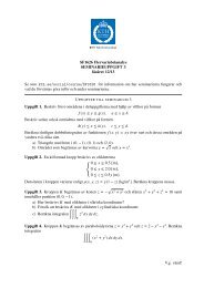
EG2040 Wind Power Systems Assignment 4 â Blade design
EG2040 Wind Power Systems Assignment 4 â Blade design
EG2040 Wind Power Systems Assignment 4 â Blade design
Create successful ePaper yourself
Turn your PDF publications into a flip-book with our unique Google optimized e-Paper software.
<strong>EG2040</strong> <strong>Wind</strong> <strong>Power</strong> <strong>Systems</strong><br />
<strong>Assignment</strong> 4 – <strong>Blade</strong> <strong>design</strong><br />
Deadline for full credits: Thursday 11 April, 17.00<br />
Theassignmentsshouldbecompletedindividuallyandthereportcontainingallsolutionsshouldbesubmitted<br />
in the blue box marked <strong>EG2040</strong>, outside the student room at Teknikringen 33. If Matlab is used for<br />
completing the assignment the code should be included with the report.<br />
Solutions to the assignments should be well motivated and explained in detail. All equations used should be<br />
written clearly and all variables clarified. Figures and tables should be properly scaled and have captions.<br />
Write your name and student number on the front page of the assignment.<br />
The teaching assistant will be available to answer questions during the scheduled course assistance hours.<br />
In this assignment, we want to <strong>design</strong> the Betz optimum blade for a two- and a three-bladed machine. The<br />
same airfoil was chosen for both machines. The lift-to-drag ratio and the lift coefficient of the airfoil against<br />
the angle of attack are given in figure 1 below, and the exact values from these curves can be found in table 1.<br />
The curves giving the power coefficient against the tip speed ratio for typical two- and three-bladed machines<br />
can be found in figure 2.<br />
Questions<br />
1. Give formulas (you do not need to derive them) for calculating the chord length and the twist<br />
angle of the Betz optimum blade. The twist angle is here defined as the angle between the chord<br />
line and the plane of blade rotation. Assume a pitch angle of zero. Explain all introduced symbols<br />
and quantities that appear in the formulas and draw a figure explaining the angles.<br />
2. Apply the formulas to a three- and a two-bladed machine for blades with radius R = 32+C (where<br />
C is the last two digits of your personal number divided by 10) and a pitch angle of zero: explain<br />
how you select the values of the parameters appearing in the formulas, and fill in the table below,<br />
with r being the distance from the hub along the blade in meter.<br />
3. Explain why the blades have to be twisted.<br />
Three bladed Two bladed<br />
r/R r [m] c(r) θ T [deg] c(r) θ T [deg]<br />
0.1<br />
0.2<br />
0.3<br />
0.4<br />
0.5<br />
0.6<br />
0.7<br />
0.8<br />
0.9<br />
1.0<br />
1
Lift to drag ratio<br />
13<br />
12<br />
11<br />
10<br />
9<br />
8<br />
7<br />
6<br />
5<br />
4<br />
3<br />
2<br />
1<br />
0<br />
−4 −2 0 2 4 6 8 10 12<br />
Angle of attack<br />
Lift coefficient<br />
1<br />
0.75<br />
0.5<br />
0.25<br />
0<br />
−0.25<br />
−0.5<br />
−0.75<br />
−4 −2 0 2 4 6 8 10 12<br />
Angle of attack<br />
Figure 1: Lift-to-drag ratio and lift coefficient against angle of attack<br />
Table 1: Some values from the curves in figure 1<br />
Angle of attack [deg] Value of the lift to drag ratio Value of the lift coefficient<br />
-4 0 -0.7690<br />
-2 5 -0.4247<br />
0 9 0<br />
2 11.5 0.4247<br />
4 12.5 0.769<br />
6 13 0.9677<br />
8 12.4 0.9832<br />
10 11.5 0.8125<br />
12 10 0.4879<br />
0.5<br />
Three-bladed machine<br />
Two-bladed machine<br />
<strong>Power</strong> Coefficient<br />
0.4<br />
0.3<br />
0.2<br />
0.1<br />
0<br />
0 1 2 3 4 5 6 7 8 9 101112131415<br />
Tip speed ratio<br />
Figure 2: <strong>Power</strong> coefficient against tip speed ratio<br />
2


