Threaded safety valves compact perfromance type 437/459 - Leser.ru
Threaded safety valves compact perfromance type 437/459 - Leser.ru
Threaded safety valves compact perfromance type 437/459 - Leser.ru

You also want an ePaper? Increase the reach of your titles
YUMPU automatically turns print PDFs into web optimized ePapers that Google loves.
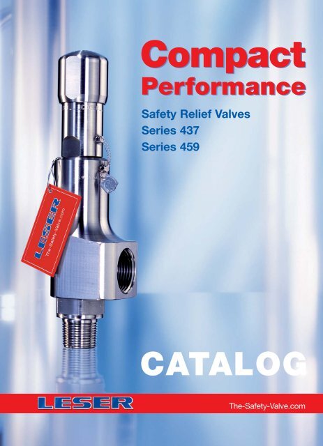
Compact<br />
Performance<br />
Safety Relief Valves<br />
Series <strong>437</strong><br />
Series <strong>459</strong><br />
CATALOG<br />
The-Safety-Valve.com
Product Range<br />
LESER Safety Valves for every industrial application<br />
Compact<br />
Performance<br />
High<br />
Performance<br />
Series <strong>437</strong><br />
API<br />
Type <strong>437</strong><br />
Type 438<br />
Type 439<br />
High<br />
Efficiency<br />
Clean<br />
Service<br />
Series <strong>459</strong><br />
H 2<br />
SO 4<br />
HNO 3<br />
NH 3<br />
HCL<br />
Critical<br />
Service<br />
Type <strong>459</strong><br />
Type <strong>459</strong> HDD<br />
Modulate<br />
Action<br />
Type 462<br />
Type 462 HDD<br />
Best<br />
Availability
General<br />
Type <strong>437</strong><br />
Orifice diameter d 0 6, 10 mm<br />
Set pressure 0.1 – 365 bar, 1.5 – 5294 psig<br />
Sealing metal to metal and soft seal (sealing plate)<br />
Type 438<br />
Orifice diameter d 0 10 mm<br />
Set pressure 5 – 180 bar, 72.5 – 2611 psig<br />
O-ring soft seal<br />
Type 439<br />
Orifice diameter d 0 10 mm<br />
Set pressure 0.1 – 16 bar, 1.5 – 232 psig<br />
Vulcanized soft seal<br />
Options Series <strong>437</strong><br />
Type <strong>459</strong><br />
Orifice diameter d 0 9, 13, 17.5 mm<br />
Set pressure 0.2 – 250 bar, 2.9 – 3626 psig<br />
Sealing metal to metal and soft seal (sealing plate)<br />
Type <strong>459</strong> HDD<br />
Orifice diameter d 0 6, 9, 13 mm<br />
Set pressure 0.2 – 850 bar, 2.9 – 12328 psig<br />
Sealing stellited metal to metal<br />
Type 462<br />
Orifice diameter d 0 9, 13, 17.5 mm<br />
Set pressure 0.5 – 250 bar, 7.2 – 3626 psig<br />
O-ring soft seal<br />
Type 462 HDD<br />
Orifice diameter d 0 9, 13 mm<br />
Set pressure 0.5 – 350 bar, 7.2 – 5076 psig<br />
O-ring soft seal<br />
Options Series <strong>459</strong>
Contents<br />
Overview<br />
Chapter/Page<br />
General 00/01<br />
Applications, General design features 00/02<br />
Valve finder 00/03<br />
Valve selection 00/05<br />
How to use: Signs and symbols 00/07<br />
How to use: Determination of coefficient 00/08<br />
of discharge K dr / w<br />
How to use: Capacity sheets 00/09<br />
LESER Effective Orifice LEO S/G<br />
LESER Effective Orifice LEO L<br />
LESER Type<br />
Materials<br />
00/11<br />
Type <strong>437</strong> 01/01<br />
• Available designs 01/02<br />
• Available designs – materials 01/03<br />
How to order<br />
• Numbering system 01/04<br />
• Article numbers 01/06<br />
Dimensions and weights<br />
• Metric Units [<strong>Threaded</strong> connection] 01/08<br />
[Flanged connection] 01/09<br />
• US Units [<strong>Threaded</strong> connection] 01/10<br />
[Flanged connection] 01/11<br />
Pressure temperature ratings<br />
Chapter/Page<br />
• Metric Units + US Units 01/12<br />
Order information – Spare parts 01/13<br />
Available options 01/14<br />
Approvals 01/15<br />
Capacities<br />
• Steam [Metric Units + US Units] 01/16<br />
• Air [Metric Units + US Units] 01/17<br />
• Water [Metric Units + US Units] 01/18<br />
Determination of coefficient of discharge K dr / w 01/19<br />
Application range of conventional design and long version 01/20<br />
Type 438 02/01<br />
Materials<br />
• Available designs 02/02<br />
• Available designs – materials 02/03<br />
How to order<br />
• Numbering system 02/04<br />
• Article numbers 02/06<br />
Type 438<br />
Dimensions and weights<br />
• Metric Units [<strong>Threaded</strong> connection] 02/08<br />
[Flanged connection] 02/09<br />
• US Units [<strong>Threaded</strong> connection] 02/10<br />
[Flanged connection] 02/11<br />
Pressure temperature ratings<br />
• Metric Units + US Units 02/12<br />
Order information – Spare parts 02/13<br />
Available options 02/14<br />
Approvals 02/15<br />
Capacities<br />
• Steam, Air, Water [Metric Units + US Units] 02/16<br />
Determination of coefficient of discharge K dr / w 02/17<br />
Application range of conventional design and long version 02/18<br />
Type 439 03/01<br />
Materials<br />
• Available designs 03/02<br />
• Available designs – materials 03/03<br />
How to order<br />
• Numbering system 03/04<br />
• Article numbers 03/06<br />
Pressure temperature ratings<br />
• Metric Units + US Units 03/07<br />
Dimensions and weights<br />
• Metric Units [<strong>Threaded</strong> connection] 03/08<br />
[Flanged connection] 03/09<br />
• US Units [<strong>Threaded</strong> connection] 03/10<br />
[Flanged connection] 03/11<br />
Order information – Spare parts 03/12<br />
Available options 03/13<br />
Approvals 03/14<br />
Capacities<br />
• Steam, Air, Water [Metric Units + US Units] 03/15<br />
Determination of coefficient of discharge K dr / w 03/16<br />
Options 04/01<br />
Overview 04/02<br />
Caps and Levers 04/03<br />
<strong>Threaded</strong> connections 04/04<br />
Flanged connections 04/05<br />
Connections and fittings 04/06<br />
INCONEL X-750 spring 04/07<br />
Type of sealing 04/08<br />
Soft seal material selection 04/10<br />
Heating jacket 04/11<br />
Installing note 04/12<br />
Type <strong>437</strong><br />
Packed knob H4<br />
Type <strong>437</strong><br />
Packed knob H4<br />
Long version<br />
Type <strong>437</strong><br />
Pull button H3<br />
Type <strong>437</strong><br />
Packed knob H4<br />
Certified for horizontal fitting<br />
Type <strong>437</strong><br />
Cap H2<br />
Flange connection
Contents<br />
Type <strong>459</strong> 05/01<br />
Materials<br />
• Available designs 05/02<br />
• Available designs – materials 05/03<br />
How to order<br />
• Numbering system 05/04<br />
• Article numbers 05/06<br />
Dimensions and weights<br />
• Metric Units [<strong>Threaded</strong> connection] 05/08<br />
[Flanged connection] 05/09<br />
• US Units [<strong>Threaded</strong> connection] 05/10<br />
[Flanged connection] 05/11<br />
Pressure temperature ratings<br />
• Metric Units 05/12<br />
• US Units 05/13<br />
Order information – Spare parts 05/14<br />
Available options 05/16<br />
Approvals 05/17<br />
Capacities<br />
• Metric Units [Steam, Air, Water] 05/18<br />
• US Units [Steam, Air, Water] 05/19<br />
Determination of coefficient of discharge K dr / w 05/20<br />
Type <strong>459</strong> HDD 06/01<br />
Materials<br />
• Available designs 06/02<br />
• Available designs – materials 06/03<br />
How to order<br />
• Numbering system 06/04<br />
• Article numbers 06/06<br />
Dimensions and weights<br />
• Metric Units [<strong>Threaded</strong> connection] 06/08<br />
[Flanged connection] 06/09<br />
• US Units [<strong>Threaded</strong> connection] 06/10<br />
[Flanged connection] 06/11<br />
Pressure temperature ratings<br />
• Metric Units + US Units 06/12<br />
Order information – Spare parts 06/13<br />
Available options 06/14<br />
Approvals 06/15<br />
Capacities<br />
• Metric Units [Steam, Air, Water] 06/16<br />
• US Units [Steam, Air, Water] 06/17<br />
Determination of coefficient of discharge K dr / w 06/18<br />
Type 462 07/01<br />
Materials<br />
• Available designs 07/02<br />
• Available designs – materials 07/03<br />
How to order<br />
• Numbering system 07/04<br />
• Article numbers 07/06<br />
Type 462<br />
Dimensions and weights<br />
• Metric Units [<strong>Threaded</strong> connection] 07/08<br />
[Flanged connection] 07/09<br />
• US Units [<strong>Threaded</strong> connection] 07/10<br />
[Flanged connection] 07/11<br />
Pressure temperature ratings<br />
• Metric Units 07/12<br />
• US Units 07/13<br />
Order information - Spare parts 07/14<br />
Available options 07/16<br />
Approvals 07/17<br />
Capacities<br />
• Metric Units [Steam, Air, Water] 07/18<br />
• US Units [Steam, Air, Water] 07/19<br />
Determination of coefficient of discharge K dr / w 07/20<br />
Type 462 HDD 08/01<br />
Materials<br />
• Available designs 08/02<br />
• Available designs – materials 08/03<br />
How to order<br />
• Numbering system 08/04<br />
• Article numbers 08/06<br />
Dimensions and weights<br />
• Metric Units [<strong>Threaded</strong> connection] 08/08<br />
[Flanged connection] 08/09<br />
• US Units [<strong>Threaded</strong> connection] 08/10<br />
[Flanged connection] 08/11<br />
Pressure temperature ratings<br />
• Metric Units + US Units 08/12<br />
Order information – Spare parts 08/13<br />
Available options 08/14<br />
Approvals 08/15<br />
Capacities<br />
• Metric Units [Steam, Air, Water] 08/16<br />
• US Units [Steam, Air, Water] 08/17<br />
Determination of coefficient of discharge K dr / w 08/18<br />
Options 09/01<br />
Overview 09/02<br />
Caps and Levers 09/04<br />
<strong>Threaded</strong> connections 09/06<br />
Flanged connections 09/07<br />
Connections and fittings 09/08<br />
Sour gas service 09/09<br />
Type of sealing 09/10<br />
Soft seal material selection 09/12<br />
Heating jacket 09/13<br />
Balanced bellows 09/14<br />
INCONEL X-750 spring 09/15<br />
O-ring damper 09/16<br />
Lift indicator 09/18<br />
Lift restriction 09/19<br />
Type <strong>459</strong><br />
Cap H2<br />
Type <strong>459</strong><br />
Plain lever H3<br />
Type <strong>459</strong> HDD<br />
Packed lever H4<br />
Type <strong>459</strong><br />
Cap H2<br />
Balanced bellows design<br />
Type <strong>459</strong><br />
Cap H2<br />
Flange connection
General<br />
General Information<br />
LESER –<br />
Compact Performance Safety Valves<br />
This product group stands for<br />
Compact dimensions with high capacity relative<br />
to the <strong>safety</strong> valve size<br />
Great variety of threaded and flanged connections<br />
Wide pressure range<br />
LESER´s Compact Performance Safety Valves<br />
• Are designed to meet all industrial applications up to F orifice<br />
• Open rapidly with an overpressure of max. 5 % (Series <strong>459</strong>)<br />
resp. 10 % (Series <strong>437</strong>) to the full design lift.<br />
• Have a maximum blowdown of minus 10 % for steam / gas<br />
service and minus 20 % for liquid service.<br />
• Are developed in a close cooperation with plant engineers<br />
and service specialists.<br />
• Serve for protection of processes and equipment.<br />
• Are approved by all important approval organisations<br />
worldwide which ensures the worldwide applicability e. g.:<br />
• European Community: CE-marking according to the<br />
Pressure Equipment Directive (PED) 97/23/EC and<br />
EN ISO 4126-1<br />
• USA: UV-stamp according to ASME Section VIII Division 1,<br />
National Board certified capacities<br />
• Germany: VdTÜV approval according to PED,<br />
EN ISO 4126-1, TÜV SV 100 and AD 2000-Merkblatt A2<br />
• Canada: Canadian Registration Number according<br />
to the requirements of particular provinces<br />
• China: AQSIQ based on the approval according to<br />
ASME Section VIII Division 1 and AD 2000-Merkblatt A2<br />
Furthermore, all LESER Compact Performance Safety Valves<br />
are designed, marked, produced and approved according to the<br />
requirements of the following regulations (directives, codes, <strong>ru</strong>les<br />
and standards).<br />
EN ISO 4126-7, EN 12266-1 / -2, ISO 7-1 threads, ISO 228<br />
threads, DIN EN 1092 Part I and II flanging ASME PTC 25,<br />
ASME-Code Sec. II, ASME B 16.34, ASME B1.20.1 threads<br />
and ASME B16.5 flanging, API Std. 527, API RP 576<br />
AD 2000-Merkblatt A4, AD 2000-Merkblatt HP0, TRD 110,<br />
TRD 421, TRD 721<br />
00/01
General Information<br />
General<br />
Applications<br />
LESER – Compact Performance Safety Valves<br />
offer ultimate protection against unallowable overpressures<br />
in all applications for steam, gases and<br />
liquids where smaller capacities are required.<br />
Typical applications for LESER Compact Performance<br />
Safety Valves are:<br />
• Air / gas compressors and pumps<br />
• Technical gases and CO 2 plants<br />
• Cylinder filling stations<br />
• Chemical equipment and piping<br />
• Pressure vessels and piping systems containing gas,<br />
air, liquid or steam<br />
• LPG / LNG terminals, carriers etc.<br />
• Cryogenic systems and oxygen applications<br />
• Thermal relief<br />
• High pressure extraction plants<br />
General Design Features<br />
LESER´s Compact Performance Safety Valves<br />
cover a large variety of <strong>type</strong>s, materials and<br />
options to fit any application:<br />
• Connection sizes from 3 / 8 " to 1 1 / 2 " and 5 orifices<br />
(D through F) provide high suitability to the application<br />
• <strong>Threaded</strong> connections, male and female, according to<br />
all international standards guarantee worldwide applicability<br />
• Flanged connections according ANSI, DIN and JIS<br />
guarantee a worldwide applicability<br />
• Inlet pressure ratings up to PN 700 / Class 2500 to fit all<br />
required design pressures<br />
• 2 standard based / inlet body materials, Chrome steel and<br />
stainless steel as well as 3 standard body materials, ductile<br />
iron, steel and stainless steel can be selected according to<br />
the application<br />
• All parts can be machined from bar materials to cover<br />
special material requirements such as Hastelloy ® , Duplex,<br />
Super Duplex, Tantalum or Titanium within<br />
unrivalled lead time<br />
• Set pressures from 0.1 to 850 bar / 1.5 to 12328 psig<br />
make Compact Performance <strong>safety</strong> <strong>valves</strong> suitable for all<br />
industrial processes<br />
• Operating temperatures from -270 to 550 °C / -454 to<br />
1022 °F (acc. to DIN EN) cover a wide range of applications<br />
• One design and spring (single trim) for steam, gas and<br />
liquid applications reduces the number of spare parts<br />
and ensures low cost maintenance management<br />
• Ringless design needs no trim adjustments for easy<br />
maintenance<br />
• One-piece spindle reduces friction which leads to high<br />
operation accuracy<br />
• Self-draining body design, avoids residues and reduces<br />
corrosion<br />
LESER´s Compact Performance Safety Valves<br />
can be customized with a great variety of options, e. g.:<br />
• Special connections specified by the customer for<br />
optimised adaptation to the plant<br />
• Stellited or hardened metal sealing for longer product life<br />
• Soft seat solutions for superior tightness<br />
• Stainless steel bellows for back pressure compensation<br />
• Heating jackets for applications with high viscosity fluids<br />
• Base / inlet body, body, bonnet and all internal parts can<br />
be produced in special materials exactly to meet customer<br />
specification requirements<br />
00/02
General<br />
Valve finder<br />
How to find the right Product Group<br />
High operating to set<br />
pressure ratio, high backpressure<br />
or low total height?<br />
Yes<br />
High<br />
Efficiency<br />
Mediumcontrolled<br />
No<br />
Clean Service<br />
application?<br />
Yes<br />
Clean<br />
Service<br />
No<br />
Critical Service / highly corrosive<br />
application?<br />
Yes<br />
Critical<br />
Service<br />
No<br />
API specified<br />
application?<br />
No<br />
Steam, gas and liquid application<br />
with low capacity in relation<br />
to valve size?<br />
Yes<br />
Yes<br />
API<br />
Modulate<br />
Action<br />
Spring loaded<br />
Safety Valves<br />
No<br />
Orifice ≥ F<br />
High<br />
Performance<br />
Required<br />
Orifice letter?<br />
Orifice ≤ F<br />
Compact<br />
Performance<br />
Additional components<br />
beyond <strong>safety</strong> <strong>valves</strong><br />
Yes<br />
Best<br />
Availability<br />
Changeover<br />
valve<br />
Bursting<br />
disc<br />
00/03
Valve finder<br />
General<br />
How to find the right Safety Valve<br />
Set pressure<br />
[barg]<br />
850<br />
700<br />
590<br />
[psig]<br />
12328<br />
10153<br />
8557<br />
<strong>459</strong> HDD<br />
d 0 6<br />
Metal to metal seat<br />
420<br />
365<br />
350<br />
330<br />
6092<br />
5294<br />
5076<br />
4786<br />
<strong>437</strong> d 0 6<br />
Long<br />
Version<br />
<strong>459</strong> HDD d 0 9<br />
250<br />
200<br />
180<br />
100<br />
93<br />
68<br />
3626<br />
2901<br />
2611<br />
1450<br />
1349<br />
986<br />
<strong>437</strong> d 0 10<br />
Long<br />
Version<br />
<strong>437</strong> d 0 10<br />
<strong>459</strong> d 0 9<br />
<strong>459</strong> d 0 13 /<br />
<strong>459</strong> HDD d 0 13<br />
<strong>459</strong> d 0 17.5<br />
16<br />
232<br />
0<br />
0<br />
0,5 x D<br />
0.05<br />
D E F<br />
0.1 0.15<br />
0.2 0.3<br />
Orifice<br />
LEO [inch2]<br />
Set pressure<br />
[barg]<br />
850<br />
700<br />
590<br />
420<br />
[psig]<br />
12328<br />
10153<br />
8557<br />
6092<br />
365<br />
5294<br />
350<br />
330<br />
5076<br />
4786<br />
462 HDD d 0 9<br />
Soft seal<br />
250<br />
200<br />
3626<br />
2901<br />
462 d 0 9<br />
180<br />
100<br />
2611<br />
1450<br />
438 d 0 10<br />
Long Version<br />
462 d 0 13 /<br />
462 HDD d 0 13<br />
93<br />
68<br />
1349<br />
986<br />
438 d 0 10<br />
462 d 0 17.5<br />
16<br />
0<br />
232<br />
0<br />
439 d 0 10<br />
0,5 x D<br />
D E F<br />
0.05 0.1 0.15<br />
0.2 0.3<br />
Orifice<br />
LEO [inch2]<br />
Tightness<br />
Type 439<br />
Series <strong>437</strong> Series <strong>459</strong><br />
Vulcanized<br />
soft seal<br />
Type 438 O-ring-disc Type 462<br />
O-ring-disc<br />
Tightness<br />
requirement<br />
Type <strong>437</strong><br />
Sealing plate<br />
Type <strong>459</strong><br />
Sealing plate<br />
Type <strong>437</strong><br />
Metal to metal<br />
Type <strong>459</strong><br />
Metal to metal<br />
Capacity<br />
How to find<br />
the right Compact Performance<br />
Safety Valve<br />
00/04
General<br />
Valve selection<br />
Valve size<br />
Type <strong>437</strong> <strong>437</strong> 438 438 439<br />
Long version<br />
Long version<br />
Actual Orifice diameter d 0 [mm] – 6 – – –<br />
Actual Orifice diameter d 0 [inch] – 0.236 – – –<br />
Actual Orifice diameter d 0 [mm] 10 10 10 10 10<br />
Actual Orifice diameter d 0 [inch] 0.394 0.394 0.394 0.394 0.394<br />
Sealing<br />
Type Metal seat Metal seat O-ring sealing O-ring sealing Vulcanized soft seal<br />
Capacity<br />
LEOS/G d 0 6 [mm] – 0.021 – – –<br />
LEOS/G d 0 10 [mm] 0.057 0.057 0.057 0.051 0.051<br />
LEOL d 0 6 [mm] – 0.022 – – –<br />
LEOL d 0 10 [mm] 0.062 0.062 0.060 0.060 0.060<br />
Metric units<br />
US units<br />
Set pressure<br />
Temperature range<br />
Acc. DIN EN<br />
Acc. ASME<br />
Materials<br />
Type <strong>437</strong>3 <strong>437</strong>4 <strong>437</strong>3 <strong>437</strong>4 4383 4384 4383 4384 4393 4394<br />
Long version<br />
Long version<br />
1.4104 SA 479 430 – – – – –<br />
1.4404 SA 479 316L – – – – – <br />
min. p [bar] 0.1 0.1 93 68 5 5 93 68 0.1 0.1<br />
max. p [bar] 93 68 365 330 93 68 180 180 16 16<br />
min. p [psig] 1.5 1.5 1349 986 72.5 72.5 1349 986 1.5 1.5<br />
max. p [psig] 1348 986 5294 4786 1349 986 2611 2611 232 232<br />
min. [°C] -10 -270 -10 -270 -10 -45 -10 -45 -10 -45<br />
max. [°C] 220 280 220 280 150 150 150 150 150 150<br />
min. [°F] 14 -454 14 -454 14 -49 14 -49 14 -49<br />
max. [°F] 428 536 428 536 302 302 302 302 302 302<br />
min. [°C] -29 -268 -29 -268 -29 -45 -29 -45 -29 -45<br />
max. [°C] 220 280 220 280 150 150 150 150 150 150<br />
min. [°F] -20 -450 -20 -450 -20 -49 -20 -49 -20 -49<br />
max. [°F] 428 536 428 536 302 302 302 302 302 302<br />
The temperature range for Type 438 and 439 are restricted by the material of the soft seal. The specified values are related to EPDM.<br />
Approvals<br />
Country Code Media<br />
Europe PED / DIN EN ISO 4126-1 S/G/L<br />
Germany PED / AD 2000-Merkblatt A2 S/G/L<br />
USA ASME Sec. VIII Div. 1 S/G/L<br />
Canada ASME Sec. VIII Div. 1 S/G/L<br />
China AQSIQ S/G/L<br />
Russia TR / RTN S/G/L<br />
Kazakhstan GOST-K S/G/L<br />
Bela<strong>ru</strong>s GOSPROMNADZOR S/G/L<br />
Klassifikationsgesellschaften<br />
Bureau Veritas (BV) Det Norske Veritas (DNV) Germanischer Lloyd (GL)<br />
Lloyd`s Register EMEA (LREMEA) Registro Italiano Navale (RINA) U.S. Coast Guard (U.S.C.G.)<br />
00/05
Valve selection<br />
General<br />
Valve size<br />
Type <strong>459</strong>3 <strong>459</strong> HDD 462 462 HDD<br />
Actual Orifice diameter d 0 [mm] 9 6 9 9<br />
Actual Orifice diameter d 0 [inch] 0.354 0.236 0.354 0.354<br />
Actual Orifice diameter d 0 [mm] 13 9 13 13<br />
Actual Orifice diameter d 0 [inch] 0.512 0.354 0.512 0.512<br />
Actual Orifice diameter d 0 [mm] 17.5 13 17.5 –<br />
Actual Orifice diameter d 0 [inch] 0.689 0.512 0.689 –<br />
Sealing<br />
Capacity<br />
Type Metal seat Metal seat O-ring sealing O-ring sealing<br />
LEO S/G d 0 6 [mm] – 0.036 – –<br />
LEO S/G d 0 9 [mm] 0.082 0.082 0.082 0.082<br />
LEO S/G d 0 13 [mm] 0.171 0.171 0.171 0.171<br />
LEO S/G d 0 17,5 [mm] 0310 – 0.310 –<br />
LEO L d 0 6 [mm] – 0.038 – –<br />
LEO L d 0 9 [mm] 0.086 0.086 0.086 0.86<br />
LEO L d 0 13 [mm] 0.179 0.179 0.179 0.179<br />
LEO L d 0 17,5 [mm] 0.325 – 0.325 –<br />
Orifice<br />
Orifice S/G 1.01 x F 1.5 x D 1.01 x F 1.5 x D<br />
OrificeL 1.05 x F 1.6 x D 1.05 x F 1.05 x F<br />
Materials<br />
Type <strong>459</strong>3 <strong>459</strong>2 <strong>459</strong>4 <strong>459</strong>4 HDD 4623 4622 4624 4624 HDD<br />
1.4104 / 0.7043 430/ Duktil Gr. 60-40-18 – – – – – –<br />
1.0619 WCB – – – – – –<br />
1.4404 SA 479 316L – – – – <br />
Metric Units<br />
US Units<br />
Set pressure<br />
min. p [bar] 0.2 0.2 0.2 250 0.5 0.5 0.5 250<br />
max. p [bar] 250 250 250 850 250 250 250 350<br />
min. p [psig] 2.9 2.9 2.9 3626 7.3 7.3 7.3 3626<br />
max. p [psig] 3626 3626 3626 12325 3626 3626 3626 5076<br />
The temperature is limited by soft seal material. The stated values are valid for EPDM.<br />
Temperature range<br />
Acc. to DIN EN<br />
Acc. to ASME<br />
Approvals<br />
min. [°C] -10 -85 -200 -270 -10 -45 -45 -45<br />
max. [°C] 300 400 400 550 150 150 150 150<br />
min. [°F] 14 -121 -328 -454 14 -49 -49 -49<br />
max. [°F] 572 752 752 1022 302 302 302 302<br />
min. [°C] -29 -29 -184 -268 -29 -45 -45 -45<br />
max. [°C] 300 427 427 538 150 150 150 150<br />
min. [°F] -20 -20 -300 -450 -20 -49 -49 -49<br />
max. [°F] 572 800 800 1000 302 302 302 302<br />
Country Code Media<br />
Europe PED / DIN EN ISO 4126-1 S/G/L<br />
Germany PED / AD 2000-Merkblatt A2 S/G/L<br />
USA ASME Sec. VIII Div. 1 S/G/L<br />
Canada ASME Sec. VIII Div. 1 S/G/L<br />
China AQSIQ S/G/L<br />
Russia TR / RTN S/G/L<br />
Kazakhstan GOST-K S/G/L<br />
Bela<strong>ru</strong>s GOSPROMNADZOR S/G/L<br />
Klassifikationsgesellschaften<br />
Bureau Veritas (BV) Det Norske Veritas (DNV) Germanischer Lloyd (GL)<br />
Lloyd`s Register EMEA (LREMEA) Registro Italiano Navale (RINA) U.S. Coast Guard (U.S.C.G.)<br />
00/06
General<br />
How to use<br />
General signs and symbols<br />
*<br />
<br />
–<br />
Standard<br />
Available<br />
Not possible<br />
Signs and symbols for flange drillings and flange facings<br />
Standard design, no option code required<br />
*<br />
–<br />
Flange drilling / facing is not possible<br />
( * )<br />
Flange dimensions except flange thickness are in accordance with flange standard (e. g. ASME B16.5)<br />
Flange thickness is smaller (max. 2 mm), see “Multiple pressure rating”<br />
Option code for flange drilling and dimension, e. g. I22<br />
I22<br />
Flange drilling as specified in flange standard<br />
Outer flange diameter, flange thickness and height of flange facing may be larger, see “Dimensions”<br />
Option code for flange facing, e. g. L36<br />
L36<br />
Flange facing as specified in flange standard (e.g. Flange facing inlet Type B2 “smooth finish”)<br />
General information concerning flange drillings and flange facings<br />
Flange dimensions of LESER Series <strong>437</strong>, <strong>459</strong> exceed flange dimension as mentioned in ASME / ANSI B16.5 and<br />
DIN EN 1092. This exceed is in accordance with API Standard 526, Section 2.4.<br />
Dimensions<br />
Dimensions: “For some valve designs, the inlet raised face height may substantially exceed the nominal dimension<br />
specified in ASME / ANSI B16.5 (and DIN EN 1092). Consult the manufacturer for exact dimension.”<br />
The reason for this exceed is:<br />
- height of nozzle placed in the inlet of valve<br />
- the slip on flange const<strong>ru</strong>ction<br />
Multiple<br />
pressure rating<br />
Smooth finish<br />
Stock finish<br />
The flange standard shows the same drilling, facing and outer diameter for several pressure ratings, e. g. PN 16 up to<br />
PN 40. Due to the pressure rating of the machined slip on flanges LESER fulfills the requirements for flange thickness<br />
e. g. of PN 16 but not PN 40<br />
The effective MSS SP-6 (Edition 2001) does not mention “smooth finish” anymore.<br />
In MSS SP-6 (Edition 1980) “smooth finish” is defined for finishes of contact flanges as “250 μinch (6.3 μm) AARH max.”.<br />
LESER supplies flange facings according to ASME B16.5 – 1996, paragraph 6.4.4.3:<br />
“Either a serrated concentric or serrated spiral finish resulting in service finish from 125 μinch to 250 μinch average<br />
roughness shall be furnished.” This finish meets the requirements of MSS SP-6 (Edition 1980), which is not valid anymore!<br />
Stock finish is not defined in any technical standard. If purchase orders show “stock finish” LESER supplies standard<br />
facing according to DIN or ASME (marked with * in table “Flange facings” of each valve series).<br />
Materials<br />
Please find below a summary of material codes at LESER. Please note that<br />
- for every body material an inspection certificate 3.1 according to EN 10204 is available<br />
- many materials have a multiple inspection certificate 3.1.<br />
Material code<br />
Flanged <strong>safety</strong> valve body Body material is certified with 3.1 (EN 10204) for the following materials<br />
<strong>Threaded</strong> <strong>safety</strong> valve inlet body DIN EN ASME<br />
xxx 2.xxxx Stainless steel 1.4404 SA 479 316L<br />
xxx 3.xxxx Chrome steel 1.4104 SA 479 430<br />
xxx 4.xxxx Stainless steel 1.4404, 1.4571 SA 479 316L, 316Ti<br />
xxx X.xxxx Other materials on request e. g. 2.4610 e. g. Hastelloy ®<br />
00/07
How to use<br />
General<br />
Sample Determination of K dr / w : Type <strong>459</strong>, d 0 13 mm<br />
Type <strong>459</strong><br />
Determination of coefficient of discharge<br />
in case of lift restriction or back pressure<br />
Diagram for evaluation of ratio of lift /flow diameter (h/d 0 )<br />
in reference to the coefficient of discharge (K dr / w )<br />
1<br />
0.85<br />
d 0 Ø 13 mm<br />
K dr = α w = f (h/d 0) – S/G<br />
h = Lift [mm]<br />
d 0 = Flow diameter [mm] of selected <strong>safety</strong><br />
valve, refer to table article numbers<br />
h/d 0 = Ratio of lift / flow diameter<br />
p a0 = Back pressure [bar a]<br />
p 0 = Set pressure [bar a]<br />
p a0/p 0 = Ratio of back pressure / set pressure<br />
K dr = Coefficient of discharge<br />
acc. to DIN EN ISO 4126-1<br />
w = Coefficient of discharge<br />
acc. to AD 2000-Merkblatt A2<br />
K b = Back pressure correction factor<br />
acc. to API 520 topic 3.3<br />
1a<br />
0.60<br />
0.75<br />
0.65<br />
0.55<br />
Coefficient of discharge K dr / αw<br />
0.45<br />
0.35<br />
0.25<br />
0.15<br />
0.05<br />
0.1 0.15<br />
0.2<br />
0.25<br />
Ratio of lift / flow diameter h / d 0<br />
0.175 1b<br />
Diagram for evaluation of ratio of the coefficient of discharge (K dr / w )<br />
in reference to the ratio of back pressure/set pressure (p a0 /p 0 )<br />
0.23<br />
2<br />
0.9<br />
d 0 Ø 13 mm<br />
K dr = α w = f (p a0/p 0) and K b = f (p a0/p 0)<br />
1.10<br />
2b<br />
0.79<br />
0.8<br />
0.7<br />
1.00<br />
0.90<br />
0.97<br />
2c<br />
0.80<br />
0.6<br />
0.70<br />
0.5<br />
0.60<br />
Coefficient of discharge K dr / αw<br />
0.4<br />
0.3<br />
0.2<br />
0.1<br />
0.0<br />
0.2<br />
0.3<br />
0.4 0.5 0.6 0.7<br />
0.8<br />
0.9<br />
0.50<br />
0.40<br />
0.30<br />
0.20<br />
0.10<br />
0.00<br />
Back pressure correction factor K b<br />
Ratio of back pressure / set pressure p a0 / p 0<br />
0.30<br />
2a<br />
0.909<br />
Explanation<br />
Sample – Type <strong>459</strong>, flow diameter d 0 = 13mm, rated lift h = 3.0mm, K dr / w S/G = 0.81<br />
Diagram 1<br />
Diagram 2<br />
1 2<br />
Determination of the restricted lift due to reduced K dr / w Determination of reduced K dr / w or K 1) b due to back pressure<br />
Step Description Sample Step Description Sample<br />
Calculate the required coefficent of discharge of 1a<br />
Calculate the back pressure ratio p a0 /p 0 using the 2a<br />
1 the selected <strong>safety</strong> valve. Applicable formulas<br />
1 actual values for set pressure p 0 [bar a ] 100<br />
are stated in codes and standards.<br />
K dr / w = 0.60 and back pressure p a0 [bar a ] 30 p a0 /p 0 = 0.30<br />
2<br />
Select the starting point (0.60) at the Y-axis<br />
of the diagram.<br />
2<br />
Select the starting point (0.30) at the X-axis<br />
of the diagram.<br />
3<br />
Lay a horizontal line onto the ratio graph for<br />
identify the intersection point.<br />
3<br />
Lay a vertical line onto the ratio graph to identify<br />
the intersection point.<br />
4<br />
5<br />
Lay a vertical line to the X-axis to identify the<br />
ratio of lift / flow diameter (h/d 0 ).<br />
Calculate the restricted lift using the formulas<br />
h = d 0 x h/d 0 . (For ordering a lift restriction<br />
please use option code J51 ref. to page 09/16)<br />
1b<br />
Lay a horizontal line to the Y-axis to identify<br />
2b K dr / w = 0.79<br />
4<br />
h/d the reduced K dr / w or K b .<br />
0 = 0.175 2c K b = 0.97<br />
h = 13 x 0,175<br />
h = 2.3 mm<br />
5<br />
Calculate the sizing with the established<br />
K dr / w or K b .<br />
1)<br />
Back pressure correction factor Kb acc. to API 520 topic 3.3. For further information refer to ENGINEERING at www.leser.com/engineering<br />
00/08
General<br />
How to use<br />
Sample Capacity sheet –<br />
How to select capacities for steam: Type <strong>459</strong>, d 0 9 mm<br />
Capacities<br />
Capacities for saturated steam according to AD 2000-Merkblatt A2,<br />
based on set pressure plus 10 % overpressure.<br />
7<br />
Capacities at 1 bar (14.5 psig) and below are based on 0.1 bar<br />
(1.45 psig) overpressure.<br />
1<br />
Metric Units<br />
AD 2000-Merkblatt A2<br />
Actual Orifice diameter d 0 [mm] 9 2<br />
Actual Orifice area A 0 [mm 2 ] 63.6 3<br />
LEO* ) [inch 2 ]<br />
4<br />
S/G = 0.082 L = 0.086<br />
Set pressure<br />
Capacities<br />
5<br />
Steam Air Water<br />
saturated 0° C and 20° C<br />
1013 mbar<br />
[bar] [kg/h] [m 3 n /h] [10 3 kg/h]<br />
0.2<br />
0.5<br />
1<br />
1.5 77 92 2.54<br />
2 93 6 113 2.93<br />
Capacities for saturated steam according to ASME Section VIII (UV),<br />
based on set pressure plus 10% overpressure.<br />
Capacities at 2.07 bar (30 psig) and below are based on 0.207 bar<br />
(3 psig) overpressure.<br />
US Units<br />
ASME Section VIII<br />
Actual Orifice diameter d 0 [inch] 0.354<br />
Actual Orifice area A 0 [inch 2 ] 0.099<br />
LEO* ) [inch 2 ] S/G = 0.082 L = 0.086<br />
Set pressure<br />
Capacities<br />
Steam Air Water<br />
saturated 60° F and 70° F<br />
14,5 psig<br />
[psig] [lb/h] [S.C.F.M.] [US-G.P.M.]<br />
15 134 48 9.02<br />
20 155 55 10.2<br />
30 196 70 12.2<br />
40 242 86 14.1<br />
50 287 103 15.8<br />
* ) LEO S/G/L = LESER Effective Orifice steam / gas / liquids please refer to page 00/11<br />
Explanation<br />
Type <strong>459</strong> d 0 9mm<br />
No. Description Metric Units US Units Example<br />
1 Code AD 2000-Merkblatt A2<br />
2 Actual orifice diameter d 0 [mm] [inch] 9<br />
3 Actual orifice area A 0 [mm 2 ] [inch 2 ] 63.6<br />
4 LESER Effective Orifice LEO S/G [inch 2 ] [inch 2 ] 0.082<br />
5 Set pressure [bar g ] [psig] 2<br />
6 Capacity [kg/h] [lb/h] 93<br />
7 Base of calculation see table page 00/10<br />
00/09
How to use<br />
General<br />
7<br />
Base of capacity calculation<br />
Media<br />
Code<br />
Steam<br />
(saturated steam)<br />
Standard<br />
conditions<br />
Metric Units<br />
Capacity calculation according to<br />
AD 2000-Merkblatt A2<br />
Steam table IAPWS-IF97<br />
IAPWS Industrial Formulation for<br />
the Thermodynamic Properties<br />
of Water and Steam<br />
[kg/h]<br />
US Units<br />
Capacity calculation according to<br />
ASME Section VIII (UV)<br />
Steam table IAPWS-IF97<br />
IAPWS Industrial Formulation for<br />
the Thermodynamic Properties<br />
of Water and Steam<br />
[lb/h]<br />
Air<br />
Standard<br />
conditions<br />
0 °C and 1013 mbar [m n 3 /h] 16 °C (60 °F) [S.C.F.M.]<br />
Water<br />
Standard<br />
conditions<br />
20 °C (68 °F) [10 3 kg/h] 21 °C (70 °F) [US-G.P.M.]<br />
All Media<br />
Calculation<br />
pressure<br />
Set pressure plus 10 % overpressure<br />
Set pressure plus 10 % overpressure<br />
Calculation<br />
pressure for<br />
low set pressure<br />
Capacities at 1 bar (14.5 psig)<br />
and below are based on 0.1 bar<br />
(1.45 psig) overpressure.<br />
Capacities at 2.07 bar (30 psig)<br />
and below are based on<br />
0.207 bar (3 psig) overpressure.<br />
Example Capacity calculation pressure<br />
Metric Units<br />
US Units<br />
Set pressure Capacity calculation pressure Set pressure Capacity calculation pressure<br />
10 bar 10 bar + 10% overpressure = 11 bar 145 psig 145 psig + 10% overpressure = 159.5 psig<br />
0.5 bar 0.5 bar + 0.1 bar overpressure = 0.6 bar 20 psig 20 psig + 3 psig overpressure = 23 psig<br />
4<br />
LESER Effective Orifice<br />
Pressure relief devices may be initially sized using the equations<br />
shown in API RP 520, topic 3.6 through 3.10 as appropriate<br />
for vapors, gases, liquids, or two phase flow. These equations<br />
utilize effective coefficient of discharge (S/G 0.975, L 0.650) and<br />
effective areas (acc. to API Std. 526, Fifth Edition, June 2002,<br />
table 1) which are independent of any specific valve design.<br />
In this way the designer can determine a preliminary pressure<br />
relief valve size.<br />
By using the LESER Effective Orifice the designer can directly<br />
select a LESER <strong>safety</strong> relief valve after calculating. A verification<br />
of the sizing with the selected actual orifice and the<br />
rated coefficient of discharge is not necessary.<br />
LEO S/G<br />
LESER Effective Orifice (for steam, gas and vapor) [inch 2 ] refer to page 00/11<br />
LEO L<br />
LESER Effective Orifice (for liquid) [inch 2 ] refer to page 00/11<br />
For further information refer to ENGINEERING at www.leser.com/engineering<br />
00/10
General<br />
LEOS/G/L<br />
This table based on the rated coefficient of discharge for steams and gases of LESER <strong>safety</strong> <strong>valves</strong> certified by<br />
ASME. The appropriated K-values are shown in the column “K-value” of the table.<br />
LEO S/G<br />
LESER Effective Orifice (for steam, gas and vapor)<br />
Orifice acc.<br />
API 526<br />
LESER-Series DN Inlet size d 0 [inch] d 0 [mm] K-value<br />
LEOS/G<br />
[inch 2 ]<br />
% of higher<br />
orifice<br />
% of lower<br />
orifice<br />
<strong>437</strong> 1/ 2 " 0.236 6.0 0.458 0.021 18.7%<br />
<strong>459</strong> 10 1/ 2 " 0.236 6.0 0.811 0.036 33.1%<br />
438 1/ 2 " 0.394 10.0 0.406 0.051 46.1%<br />
439 1/ 2 " 0.394 10.0 0.406 0.051 46.1%<br />
<strong>437</strong> 1/ 2 " 0.394 10.0 0.458 0.057 52.0%<br />
<strong>459</strong> 15 3/ 4 " 0.354 9.0 0.811 0.082 74.6%<br />
462 15 3/ 4 " 0.354 9.0 0.811 0.082 74.6%<br />
D 0.110 100.0% 100.0%<br />
<strong>459</strong> 15 3/ 4 " 0.512 13.0 0.811 0.171 87.3% 155.6%<br />
462 15 3/ 4 " 0.512 13.0 0.811 0.171 87.3% 155.6%<br />
E 0.196 100.0% 100.0%<br />
F 0.307 100.0% 100.0%<br />
<strong>459</strong> 20 1" 0.689 17.5 0.811 0.310 61.7% 101.0%<br />
462 20 1" 0.689 17.5 0.811 0.310 61.7% 101.0%<br />
LEO L<br />
LESER Effective Orifice (for liquid)<br />
Orifice acc.<br />
API 526<br />
LESER-Series DN Inlet size d 0 [inch] d 0 [mm] K-value<br />
LEOL<br />
[inch 2 ]<br />
% of higher<br />
orifice<br />
% of lower<br />
orifice<br />
<strong>437</strong> 1/ 2 " 0.236 6.0 0.333 0.022 20.4%<br />
<strong>459</strong> 10 1/ 2 " 0.236 6.0 0.566 0.038 34.7%<br />
438 1/ 2 " 0.394 10.0 0.322 0.060 54.8%<br />
439 1/ 2 " 0.394 10.0 0.322 0.060 54.8%<br />
<strong>437</strong> 1/ 2 " 0.394 10.0 0.333 0.062 56.7%<br />
<strong>459</strong> 15 3/ 4 " 0.354 9.0 0.566 0.086 78.1%<br />
462 15 3/ 4 " 0.354 9.0 0.566 0.086 78.1%<br />
D 0.110 100.0% 100.0%<br />
<strong>459</strong> 15 3/ 4 " 0.512 13.0 0.566 0.179 91.4% 162.9%<br />
462 15 3/ 4 " 0.512 13.0 0.566 0.179 91.4% 162.9%<br />
E 0.196 100.0% 100.0%<br />
F 0.307 100.0% 100.0%<br />
<strong>459</strong> 20 1" 0.689 17.5 0.566 0.325 64.5% 105.7%<br />
462 20 1" 0.689 17.5 0.566 0.325 64.5% 105.7%<br />
00/13
Type<br />
Type <strong>437</strong><br />
Type <strong>437</strong><br />
Packed knob H4<br />
Conventional design<br />
<strong>437</strong><br />
Safety Relief Valves<br />
– spring loaded<br />
Type <strong>437</strong><br />
Packed knob H4<br />
Flanged connection<br />
Type <strong>437</strong><br />
Cap H2<br />
Long version<br />
Contents<br />
Chapter/Page<br />
Materials<br />
• Available designs 01/02<br />
• Available designs – materials 01/03<br />
How to order<br />
• Numbering system 01/04<br />
• Article numbers 01/06<br />
Dimensions and weights<br />
• Metric Units [<strong>Threaded</strong> connection] 01/08<br />
[Flanged connection] 01/09<br />
• US Units [<strong>Threaded</strong> connection] 01/10<br />
[Flanged connection] 01/11<br />
Pressure temperature ratings<br />
• Metric Units + US Units 01/12<br />
Order information – Spare parts 01/13<br />
Available options 01/14<br />
Approvals 01/15<br />
Capacities<br />
• Steam [Metric Units + US Units] 01/16<br />
• Air [Metric Units + US Units] 01/17<br />
• Water [Metric Units + US Units] 01/18<br />
Determination of coefficent 01/19<br />
of discharge K dr / w<br />
Application range 01/20<br />
of conventional design and long version<br />
01/01
Type <strong>437</strong><br />
Available designs<br />
Type <strong>437</strong><br />
40 Cap H2<br />
18 Adjusting screw<br />
with bushing<br />
19<br />
Lock nut<br />
Axial needle 69<br />
beering<br />
16<br />
Spring plate<br />
12 Spindle<br />
54 Spring<br />
2 Outlet body<br />
17<br />
Spring plate<br />
57<br />
Pin<br />
61<br />
Ball<br />
7 Disc<br />
1 Body<br />
Conventional design<br />
<strong>Threaded</strong> connection<br />
Long version<br />
<strong>Threaded</strong> connection<br />
Outlet flange 2.4<br />
Outlet adaptor 2.1<br />
Inlet flange 48<br />
Conventional design<br />
Flange connection<br />
01/02
Type <strong>437</strong><br />
Available designs – materials<br />
Type <strong>437</strong><br />
Materials<br />
Item Component Remarks Type <strong>437</strong>3 Type <strong>437</strong>4<br />
1 Base / Inlet body<br />
2 Outlet body<br />
<strong>Threaded</strong><br />
connection<br />
Flange connection<br />
Long version<br />
2.1 Outlet adaptor Flange connection<br />
2.4 Outlet flange Flange connection<br />
7 Disc<br />
Long version<br />
1.4104 1) , 1.4404 1.4404<br />
SA 479 430 1) , SA 479 316L<br />
SA 479 316L<br />
1.4404 1.4404<br />
SA 479 316L<br />
SA 479 316L<br />
1.4104 2) , 1.4404 Stellited 1.4404 Stellited<br />
SA 479 430 2) , SA 479 316L Stellited<br />
SA 479 316L Stellited<br />
1.4104 1.4404<br />
SA 479 430<br />
SA 479 316L<br />
1.4404 1.4404<br />
316L<br />
316L<br />
1.4404 1.4404<br />
316L<br />
316L<br />
1.4122 1.4404<br />
Hardened stainless steel<br />
SA 316L<br />
d 0 6: 1.4404 Stellited d 0 10: 1.4122 d 0 6: 1.4404 Stellited d 0 10: 1.4404<br />
d 0 6: 316L Stellited d 0 10: HSS d 0 6: 316L Stellited d 0 10: 316L<br />
1.4021 1.4571<br />
12 Spindle 3) 420 316Ti<br />
1.4571 1.4571<br />
Long version<br />
316Ti<br />
316Ti<br />
1.4104 1.4404<br />
16/17 Spring plate 3) Chrome steel<br />
316L<br />
1.4404 1.4404<br />
Long version<br />
316L<br />
316L<br />
18<br />
Adjusting screw<br />
with bushing<br />
19 Lock nut<br />
40 Cap H2<br />
48 Inlet flange Flange connection<br />
54 Spring<br />
57 Pin<br />
61 Ball<br />
69 Axial needle beering Long version<br />
1)<br />
Only for male thread DIN ISO 228-1 G 3 /8, G 1 / 2 , G 3 / 4 (Option Codes V49, V54, V55).<br />
2)<br />
Only for d 0 10 with male thread DIN ISO 228-1 G 3 / 8 , G 1 / 2 , G 3 / 4 (Option Codes V49, V54, V55).<br />
3)<br />
The items 12 and 17 are combined to one unit.<br />
1.4104 PTFE 1.4404 PTFE<br />
Chrome steel PTFE 316L PTFE<br />
1.0718 1.4404<br />
Steel<br />
316L<br />
1.0718 1.4404<br />
Steel<br />
316L<br />
1.4404 1.4404<br />
316L<br />
316L<br />
1.4310 1.4310<br />
Stainless steel<br />
Stainless steel<br />
1.4310 1.4310<br />
Stainless steel<br />
Stainless steel<br />
1.3541 1.4401<br />
Hardened stainless steel 316<br />
1.4404 1.4404<br />
316L<br />
316L<br />
Please notice:<br />
– Modifications reserved by LESER.<br />
– LESER can upgrade materials without notice.<br />
– Every part can be replaced by other material acc. to customer specification.<br />
01/03
Type <strong>437</strong><br />
How to order – Series <strong>437</strong> – Example for numbering system<br />
Type <strong>437</strong><br />
1 2 3<br />
Article Number<br />
Set Pressure<br />
Connections<br />
<strong>437</strong>4.3142 10 barg V62 V71<br />
1 2 3 4<br />
<strong>437</strong> 4 . 314 2<br />
1 Valve Type <strong>437</strong><br />
Types of sealing<br />
Metal seat<br />
Metal-to-metal<br />
Metal-to-metal stellited<br />
Soft seal (Sealing plate)<br />
SP<br />
Vespel-SP1<br />
PCTFE Kel-F<br />
PTFE-FDA Teflon<br />
Please state unit (in gauge)!<br />
Please do not exceed pressure range<br />
mentioned in the spring charts.<br />
Please refer to table<br />
“Availabe Connections”<br />
on pages 04/04 and 04/05.<br />
Please state one option code for each,<br />
inlet and outlet.<br />
2 Material code<br />
Code Body material<br />
3 1.4104 (430)<br />
4 1.4404 (316L)<br />
3 Valve code<br />
Identifies valve size, body material<br />
and orifice, refer to page 01/07<br />
and following.<br />
4 Code for lifting device<br />
Code Lifting device<br />
2 Screwed cap H2<br />
3 Pull button H3<br />
4 Packed knob H4<br />
01/04
Type <strong>437</strong><br />
Type <strong>437</strong><br />
4 5 6<br />
Options Documentation Code and Medium<br />
J44 H01 L30 2.0<br />
Type <strong>437</strong><br />
Option code<br />
Please select requested documentation:<br />
1 2<br />
• Base / Inlet body stellited L20<br />
(Type <strong>437</strong> Standard only)<br />
• Disc stellited<br />
J25<br />
• Plastic seal material<br />
PTFE “A” J44<br />
PCTFE “G” J48<br />
VESPEL SP “T” J49<br />
• INCONEL X-750 spring X08<br />
Inspections, tests: Option code<br />
DIN EN 10204-3.2: TÜV-Nord<br />
Certificate for test pressure M33<br />
LESER CGA (Certificate H03<br />
for Global Application)<br />
- Inspection certificate 3.1 acc.<br />
to DIN EN 10204<br />
- Declaration of conformity acc.<br />
to PED 97/23/EC<br />
Material test certificate:<br />
DIN EN 10204-3.1<br />
Part<br />
Option code<br />
Base / Inlet body<br />
H01<br />
Outlet body<br />
L34<br />
Cap / lever cover<br />
L31<br />
Disc<br />
L23<br />
1<br />
2<br />
2 . 0<br />
Code<br />
1. ASME Section VIII<br />
2. CE / VdTUEV<br />
3. ASME Section VIII<br />
+ CE / VdTUEV<br />
Medium<br />
.1 Gases<br />
.2 Liquids<br />
.3 Steam<br />
.0 Steam / Gases / Liquids<br />
( valid only for CE / VdTUEV)<br />
01/05
Type <strong>437</strong><br />
How to order – Article numbers<br />
Type <strong>437</strong><br />
Type <strong>437</strong> Male<br />
Outlet body 1 / 2 "<br />
Pull button H3<br />
Conventional design<br />
Type <strong>437</strong> Female<br />
Outlet body 1"<br />
Cap H2<br />
Conventional design<br />
Type <strong>437</strong> Flanged connection<br />
Outlet body 1"<br />
Cap H2<br />
Conventional design<br />
Type <strong>437</strong> Male<br />
Outlet body 1 / 2 "<br />
Packed knob H4<br />
Long version<br />
01/06
Type <strong>437</strong><br />
How to order – Article numbers<br />
Type <strong>437</strong><br />
Article numbers<br />
Conventional design<br />
Long version<br />
Actual Orifice diameter d 0 [mm] 10 6 10<br />
Actual Orifice area A 0 [mm 2 ] 78.5 28.3 78.5<br />
Actual Orifice diameter d 0 [inch] 0.394 0.236 0.394<br />
Actual Orifice area A 0 [inch 2 ] 0.122 0.044 0.122<br />
Base / Inlet body material: 1.4104 (430)<br />
H2 Art.-No. <strong>437</strong>3. 2602 2622 2612<br />
H3 Art.-No. <strong>437</strong>3.<br />
p max. = 16 bar<br />
2603 – –<br />
g<br />
H4 Art.-No. <strong>437</strong>3. 2604 2624 2614<br />
p [barg] S/G/L 0.1 – 93 S/G 180 – 365 S/G/L 93 –180<br />
p [psig] S/G/L 1.5 – 1349 S/G 2611 – 5294 S/G/L 1349 – 2611<br />
Base / Inlet body material: 1.4404 (316L)<br />
H2 Art.-No. <strong>437</strong>4. 3142 3122 3152<br />
H4 Art.-No. <strong>437</strong>4. 3144 3124 3154<br />
p [barg] S/G/L 0.1 – 68 S/G 180 – 330 S/G/L 68 –180<br />
p [psig] S/G/L 1.5 – 986 S/G 2611 – 4786 S/G/L 986 – 2611<br />
01/07
Type <strong>437</strong><br />
Dimensions and weights – Metric Units<br />
Type <strong>437</strong><br />
<strong>Threaded</strong> connections<br />
Size Outlet body<br />
Conventional design<br />
Long version<br />
/ 2 " 3 / 4 " 1" 1 / 2 " 3 / 4 " 1" 1 / 2 " 3 / 4 " 1"<br />
Actual Orifice diameter d 0 [mm] 10 10 10 6 6 6 10 10 10<br />
Actual Orifice area A 0 [mm 2 ] 78.5 78.5 78.5 28.3 28.3 28.3 78.5 78.5 78.5<br />
Weight [kg] 1.2 1.6 1.6 1.4 2.1 2.1 1.4 2.1 2.1<br />
Required installation diameter [mm] 65 80 80 65 80 80 65 80 80<br />
Inlet thread “Female”<br />
Size outlet body<br />
Conventional design<br />
1 / 2 " 3 / 4 " 1"<br />
Long version<br />
1 / 2 " 3 / 4 " 1" 1 / 2 " 3 / 4 " 1"<br />
Center to face [mm]<br />
DIN ISO 228-1 G<br />
ISO 7-1/BS 21 Rc<br />
Inlet 1 / 2 " a 46 46 49 46 46 49 46 46 49<br />
ASME B1.20.1 NPT Inlet 3 / 4 ", 1" a 56 56 59 56 56 59 56 56 59<br />
Outlet b 30 37 37 30 37 37 30 37 37<br />
Height [mm]<br />
Inlet 1 / 2 " H max. 209 209 212 230 230 233 230 230 233<br />
Inlet 3 / 4 ", 1" H max. 219 219 222 240 240 243 240 240 243<br />
Inlet thread “Male”<br />
Size outlet body<br />
Conventional design<br />
Long version<br />
1 / 2 " 3 / 4 " 1" 1 / 2 " 3 / 4 " 1" 1 / 2 " 3 / 4 " 1"<br />
Center to face [mm]<br />
DIN ISO 228-1 G<br />
Inlet a 33 33 36 33 33 36 33 33 36<br />
Outlet b 30 37 37 30 37 37 30 37 37<br />
ISO 7-1/BS 21 R<br />
ASME B1.20.1 NPT<br />
Inlet a 31 31 34 31 31 34 31 31 34<br />
Outlet b 30 37 37 30 37 37 30 37 37<br />
Height [mm]<br />
Size inlet thread<br />
Conventional design<br />
Long version<br />
/ 8 " 1 / 2 " 3 / 4 " 1" 3 / 8 " 1 / 2 " 3 / 4 " 1"<br />
DIN ISO 228-1 G H max. 208 210 212 217 229 231 233 238<br />
ISO 7-1/BS 21 R H max. – 213 214 220 – 234 235 241<br />
ASME B1.20.1 NPT H max. – 216 216 224 – 237 237 245<br />
Length of screwed end “c” [mm]<br />
Size inlet thread 3 / 8 " 1 / 2 " 3 / 4 " 1"<br />
DIN ISO 228-1 G 12 14 16 18<br />
ISO 7-1/BS 21 R – 19 20 23<br />
ASME B1.20.1 NPT – 22 22 27<br />
Available threaded connections refer to page 04/04.<br />
Required installation diameter<br />
Conventional design – Female thread Conventional design – Male thread Long version – male thread<br />
01/08
Type <strong>437</strong><br />
Dimensions and weights – Metric Units<br />
Flanged connection<br />
Conventional design<br />
Long version<br />
Actual Orifice diameter d 0 [mm] 10 6 10<br />
Actual Orifice area A 0 [mm 2 ] 78.5 28.3 78.5<br />
DIN EN 1092-1 (Available flange sizes refer to page 04/05)<br />
Flange rating class PN 40<br />
Center to face [mm] Inlet a 100 100 100<br />
Outlet b 100 100 100<br />
Height [mm] H max. 263 284 284<br />
Flange rating class ≥ PN 160<br />
Center to face [mm] Inlet a 103 103 103<br />
Outlet b 100 100 100<br />
Height [mm] H max. 266 287 287<br />
ASME B 16.5 (Available flange sizes refer to page 04/05)<br />
Flange rating class 150<br />
Center to face [mm] Inlet a 100 100 100<br />
Outlet b 100 100 100<br />
Height [mm] H max. 263 284 284<br />
Flange rating class ≥ 300<br />
Center to face [mm] Inlet a 103 103 103<br />
Outlet b 100 100 100<br />
Height [mm] H max. 266 287 287<br />
Note The outlet dimension b can differ at special combinations of nominal diameter and pressure range if flanged connections are used at the inlet and outlet.<br />
Special dimensions are possible. More information at sales@leser.com<br />
Weight<br />
To calculate the total weight use the formula: mT = m N + m F (Inlet) + m F (Outlet)<br />
Weight net [kg]<br />
(without inlet and outlet flange)<br />
2.4 2.8 2.8<br />
m N<br />
Type <strong>437</strong><br />
Flange dimensions<br />
DIN EN 1092-1 / Flange rating PN<br />
ASME B16.5 / Flange rating<br />
Size 40 100 160 250 320 400 Size 150 300 600 900 1500 2500<br />
DN 15 NPS 1 / 2 "<br />
Flange thickness [mm] s 18 – 22 28 28 30 14 18 18 26 26 30.2<br />
Weight slip on flange [kg] m F 0.8 – 1.2 2.5 2.5 3.6 0.6 0.9 0.9 2.1 2.1 3<br />
DN 20 NPS 3 / 4 "<br />
Flange thickness [mm] s 20 22 – – – – 15 18 18 25.4 25.4 32<br />
Weight slip on flange [kg] m F 1.1 1.3 – – – – 0.8 1.4 1.4 2.3 2.3 3.5<br />
DN 25 NPS 1"<br />
Flange thickness [mm] s 22 – 26 30 36 40 17 21.5 21.5 32.5 32.5 40<br />
Weight slip on flange [kg] m F 1.3 – 2.6 3.5 5 7.5 1 2.1 21 4.1 4.1 5.1<br />
a<br />
s<br />
s<br />
b<br />
Conventional design<br />
s<br />
Long version<br />
s<br />
01/09
Type <strong>437</strong><br />
Dimensions and weights – US Units<br />
Type <strong>437</strong><br />
<strong>Threaded</strong> connections<br />
Size Outlet body<br />
Conventional design<br />
Long version<br />
/ 2 " 3 / 4 " 1" 1 / 2 " 3 / 4 " 1" 1 / 2 " 3 / 4 " 1"<br />
Actual Orifice diameter d 0 [inch] 0.394 0.394 0.394 0.236 0.236 0.236 0.394 0.394 0.394<br />
Actual Orifice area A 0 [inch 2 ] 0.122 0.122 0.122 0.044 0.044 0.044 0.122 0.122 0.122<br />
Weight [lbs] 2.6 3.5 3.5 3.1 4.6 4.6 3.1 4.6 4.6<br />
Required installation diameter [inch] 2 9 / 16 3 5 / 32 3 5 / 32 2 9 / 16 3 5 / 32 3 5 / 32 2 9 / 16 3 5 / 32 3 5 / 32<br />
Inlet thread “Female”<br />
Size outlet body<br />
Conventional design<br />
1 / 2 " 3 / 4 " 1"<br />
Long version<br />
1 / 2 " 3 / 4 " 1" 1 / 2 " 3 / 4 " 1"<br />
Center to face [inch]<br />
DIN ISO 228-1 G<br />
ISO 7-1/BS 21 Rc<br />
Inlet 1 / 2 " a 1 13 / 16 1 13 / 16 1 15 / 16 1 13 / 16 1 13 / 16 1 15 / 16 1 13 / 16 1 13 / 16 1 15 / 16<br />
ASME B1.20.1 NPT Inlet 3 / 4 ", 1" a 2 7 / 32 2 7 / 32 2 5 / 16 2 7 / 32 2 7 / 32 2 5 / 16 2 7 / 32 2 7 / 32 2 5 / 16<br />
Outlet b 1 3 / 16 1 15 / 32 1 15 / 32 1 3 / 16 1 15 / 32 1 15 / 32 1 3 / 16 1 15 / 32 1 15 / 32<br />
Height [inch]<br />
Inlet 1 / 2 " H max. 8 7 / 32 8 7 / 32 8 11 / 32 8 7 / 32 8 7 / 32 8 11 / 32 8 7 / 32 8 7 / 32 8 11 / 32<br />
Inlet 3 / 4 ", 1" H max. 8 5 / 8 8 5 / 8 8 3 / 4 9 7 / 16 9 7 / 16 9 9 / 16 9 7 / 16 9 7 / 16 9 9 / 16<br />
Inlet thread “Male”<br />
Size outlet body<br />
Conventional design<br />
Long version<br />
1 / 2 " 3 / 4 " 1" 1 / 2 " 3 / 4 " 1" 1 / 2 " 3 / 4 " 1"<br />
Center to face [inch]<br />
DIN ISO 228-1<br />
ISO 7-1/BS 21<br />
ASME B1.20.1<br />
Height [inch]<br />
G<br />
R<br />
NPT<br />
Inlet a 1 5 / 16 1 5 / 16 1 13 / 32 1 5 / 16 1 5 / 16 1 13 / 32 1 5 / 16 1 5 / 16 1 13 / 32<br />
Outlet b 1 3 / 16 1 15 / 32 1 15 / 32 1 3 / 16 1 15 / 32 1 15 / 32 1 3 / 16 1 15 / 32 1 15 / 32<br />
Inlet a 1 7 / 32 1 7 / 32 1 11 / 32 1 7 / 32 1 7 / 32 1 11 / 32 1 7 / 32 1 7 / 32 1 11 / 32<br />
Outlet b 1 3 / 16 1 15 / 32 1 15 / 32 1 3 / 16 1 15 / 32 1 15 / 32 1 3 / 16 1 15 / 32 1 15 / 32<br />
Size inlet thread<br />
Conventional design<br />
Long version<br />
3 / 8 " 1 / 2 " 3 / 4 " 1" 3 / 8 " 1 / 2 " 3 / 4 " 1"<br />
DIN ISO 228-1 G H max. 8 3 / 16 8 1 / 4 8 11 / 32 8 17 / 32 9 9 3 / 32 9 5 / 32 9 3 / 8<br />
ISO 7-1/BS 21 R H max. – 8 3 / 8 8 13 / 32 8 21 / 32 – 9 7 / 32 9 1 / 4 9 15 / 32<br />
ASME B1.20.1 NPT H max. – 8 1 / 2 8 1 / 2 8 13 / 16 – 9 5 / 16 9 5 / 16 9 21 / 32<br />
Length of screwed end “c” [inch]<br />
Size inlet thread 3 / 8 " 1 / 2 " 3 / 4 " 1"<br />
DIN ISO 228-1 G 15 / 32 9 / 16 5 / 8 23 / 32<br />
ISO 7-1/BS 21 R – 3 / 4 25 / 32 29 / 32<br />
ASME B1.20.1 NPT – 7 / 8 7 / 8 1 1 / 16<br />
Available threaded connections refer to page 04/04.<br />
Required installation diameter<br />
Conventional design – Female thread Conventional design – Male thread Long version – male thread<br />
01/10
Type <strong>437</strong><br />
Dimensions and weights – US Units<br />
Flanged connection<br />
Conventional design<br />
Long version<br />
Actual Orifice diameter d 0 [inch] 0.394 0.236 0.394<br />
Actual Orifice area A 0 [inch 2 ] 0.122 0.044 0.122<br />
DIN EN 1092-1 (Available flange sizes refer to page 04/05)<br />
Flange rating PN 40<br />
Type <strong>437</strong><br />
Center to face [inch] Inlet a 3 15 / 16 3 15 / 16 3 15 / 16<br />
Outlet b 3 15 / 16 3 15 / 16 3 15 / 16<br />
Height [inch] H max. 10 11 / 32 11 3 / 16 11 3 / 16<br />
Flange rating ≥ PN 160<br />
Center to face [inch] Inlet a 4 1 / 16 4 1 / 16 4 1 / 16<br />
Outlet b 3 15 / 16 3 15 / 16 3 15 / 16<br />
Height [inch] H max. 10 15 / 32 11 5 / 16 11 5 / 16<br />
ASME B 16.5 (Available flange sizes refer to page 04/05)<br />
Flange rating class 150<br />
Center to face [inch] Inlet a 3 15 / 16 3 15 / 16 3 15 / 16<br />
Outlet b 3 15 / 16 3 15 / 16 3 15 / 16<br />
Height [inch] H max. 10 11 / 32 11 3 / 16 11 3 / 16<br />
Flange rating class ≤ 300<br />
Center to face [inch] Inlet a 4 1 / 16 4 1 / 16 4 1 / 16<br />
Outlet b 3 15 / 16 3 15 / 16 3 15 / 16<br />
Height [inch] H max. 10 15 / 32 11 5 / 16 11 5 / 16<br />
Note The outlet dimension b can differ at special combinations of nominal diameter and pressure range if flanged connections are used at the inlet and outlet.<br />
Special dimensions are possible. More information at sales@leser.com<br />
Weight<br />
To calculate the total weight use the formula: mT = m N + m F (Inlet) + m F (Outlet)<br />
Weight net [lbs]<br />
(without inlet and outlet flange)<br />
5.3 6.2 6.2<br />
m N<br />
Flange dimensions<br />
DIN EN 1092-1 / Flange rating PN<br />
ASME B16.5 / Flange rating<br />
Size 40 100 160 250 320 400 Größe 150 300 600 900 1500 2500<br />
DN 15 NPS 1 / 2 "<br />
Flange thickness [inch] s 23 / 32 – 7 / 23 8 / 32 1 3 / 32 1 3 / 9 16 / 23 16 / 23 32 / 32 1 3 / 32 1 3 / 32 1 3 / 16<br />
Weight slip on flange [lbs] m F 1.8 – 2.6 5.5 5.5 7.9 1.3 2.0 2.0 4.6 4.6 6.6<br />
DN 20 NPS 3 / 4 "<br />
Flange thickness [inch] s 25 / 7 32 / 8 – – – – 19 / 23 32 / 23 32 / 32 1 1 1 1 / 4<br />
Weight slip on flange [lbs] m F 2.4 2.9 – – – – 1.8 3.1 3.1 5.0 5.0 7.7<br />
DN 25 NPS 1"<br />
Flange thickness [inch] s 7 / 8 – 1 1 / 32 1 3 / 16 1 13 / 32 1 9 / 21 16 / 27 32 / 27 32 / 32 1 9 / 32 1 9 / 32 1 9 / 16<br />
Weight slip on flange [lbs] m F 2.9 – 5.7 7.7 11.0 16.5 2.2 4.6 4.6 9.0 9.0 11.2<br />
a<br />
s<br />
s<br />
b<br />
Conventional design<br />
s<br />
Long version<br />
s<br />
01/11
Type <strong>437</strong><br />
Pressure temperature ratings<br />
Type <strong>437</strong><br />
Metric Units<br />
Actual Orifice diameter d 0 [mm] 6 10<br />
Actual Orifice area A 0 [mm 2 ] 28.3 78.5<br />
Body material: 1.4104 (430)<br />
Base / Connection size 3 / 8 " 1 / 2 " 3 / 4 " 1" 3 / 8 " 1 / 2 " 3 / 4 " 1"<br />
Inlet Body<br />
Pressure rating PN 400 PN 320<br />
Outlet body Pressure rating PN 160 PN 160<br />
Minimum<br />
set pressure<br />
Maximum<br />
set pressure<br />
p [bar g ] S/G/L 180 [S/G only] 0.1<br />
p [bar g ] S/G/L 365 [S/G only]<br />
Temperature min [°C ] -10<br />
acc. to DIN EN max [°C ] +220<br />
16 [only H3]<br />
180<br />
Temperature min [°C ] -29<br />
acc. to ASME max [°C ] +220<br />
Body material: 1.4404 (316L)<br />
Base / Connection size 3 / 8 " 1 / 2 " 3 / 4 " 1" 3<br />
/ 8 " 1 / 2 " 3 / 4 " 1"<br />
Inlet Body<br />
Pressure rating PN 400 PN 320<br />
Outlet body Pressure rating PN 160 PN 160<br />
Minimum<br />
set pressure<br />
p [bar g ] S/G/L 180 [S/G only] 0.1<br />
Maximum<br />
set pressure<br />
p [bar g ] S/G/L 365 [S/G only] 180<br />
Temperature min [°C ] -270<br />
acc. to DIN EN max [°C ] +280<br />
Temperature min [°C ] -268<br />
acc. to ASME max [°C ] +280<br />
US Units<br />
Actual Orifice diameter d0 [inch] 0,236 0,394<br />
Actual Orifice area A0 [inch 2 ] 0,044 0,122<br />
Body material: 1.4104 (430)<br />
Base /<br />
Inlet Body<br />
Minimum<br />
set pressure<br />
Connection size 3 / 8 " 1 / 2 " 3 / 4 " 1" 3 / 8 " 1 / 2 " 3 / 4 " 1"<br />
p [psig] S/G/L 2611 1.5<br />
Maximum<br />
set pressure<br />
p [psig] S/G/L 5294<br />
Temperature min [°F ] +14<br />
acc. to DIN EN max [°F ] +428<br />
Temperature min [°F ] -20<br />
acc. to ASME max [°F ] +428<br />
Body material: 1.4404 (316L)<br />
Base /<br />
Inlet Body<br />
Minimum<br />
set pressure<br />
145 [only H3]<br />
2611<br />
Connection size 3 / 8 " 1 / 2 " 3 / 4 " 1" 3 / 8 " 1 / 2 " 3 / 4 " 1"<br />
p [psig] S/G/L 2611 1.5<br />
Maximum<br />
set pressure<br />
p [psig] S/G/L 5294 2611<br />
Temperature min [°F ] -450<br />
acc. to DIN EN max [°F ] +536<br />
Temperature min [°F ] -450<br />
acc. to ASME max [°F ] +536<br />
01/12
Type <strong>437</strong><br />
Order information – Spare parts<br />
Spare parts<br />
Type <strong>437</strong><br />
Actual Orifice diameter d 0 [mm] 6 10<br />
Actual Orifice area A 0 [mm 2 ] 28.3 78.5<br />
Actual Orifice diameter d 0 [inch] 0.236 0.394<br />
Actual Orifice area A 0 [inch 2 ] 0.044 0.122<br />
Body (Item 1): Male thread<br />
Material-No. / Art.-No.<br />
Connection Size 3 / 8 " 1 / 2 " 3 / 4 " 1" 3 / 8 " 1 / 2 " 3 / 4 " 1"<br />
DIN ISO 228-1 G 1.4104 – – – – 136.5239.9000 136.4439.9000 136.4539.9000 136.5839.9000<br />
316L – – – – 136.5249.9000 136.4449.9000 136.4549.9000 136.4849.9000<br />
316L stellited 136.5169.9000 136.4369.9000 136.5569.9000 136.6769.9000 – – – –<br />
R 316L – – – – – 136.4449.9220 136.4549.9220 136.5849.9220<br />
316L stellited – 136.4369.9220 136.5569.9220 136.6769.9220 – – – –<br />
ASME B1.20.1 NPT 316L – – – – – 136.4449.9204 136.4549.9204 136.5849.9204<br />
316L stellited – 136.4369.9204 136.5569.9204 136.6769.9204 – – – –<br />
Body (Item 1): Female thread<br />
Material-No. / Art.-No.<br />
Connection Size 3 / 8 " 1 / 2 " 3 / 4 " 1" 3 / 8 " 1 / 2 " 3 / 4 " 1"<br />
DIN ISO 228-1 G 316L – – – – – 136.4449.9210 136.4549.9210 136.5849.9210<br />
316L stellited – 136.4369.9210 136.5569.9210 136.6769.9210 – – – –<br />
ISO 7-1/BS 21 Rc 316L – – – – – 136.4449.9222 136.4549.9222 136.5849.9222<br />
316L stellited – 136.4369.9222 136.5569.9222 136.6769.9222 – 136.4449.9222 136.4549.9222 136.5869.9222<br />
ASME B1.20.1 NPT 316L – – – – – 136.4449.9211 136.4549.9211 136.5849.9211<br />
316L stellited – 136.4369.9211 136.5569.9211 136.6769.9211 – – – –<br />
Body (Item 1): Flange design<br />
Material-No. / Art.-No.<br />
DN 15 / PN 40 – 400 316L – 136.6349.9208<br />
NPS 1 / 2 "<br />
CL150 316L – 136.4449.9202<br />
CL300 – 2500 316L 136.4369.9208 136.6349.9208<br />
DN 20 / PN 40 – 160 316L 136.5569.9208 136.4549.9208<br />
NPS 3 / 4 "<br />
CL150 – 2500 316L 136.5569.9208 136.4549.9208<br />
DN 25 / PN 40 – 400 316L 136.6769.9208 136.4449.9208<br />
NPS 1"<br />
CL150 – 2500 316L 136.6769.9208 136.4449.9208<br />
Disc (Item 7): Metal to metal<br />
Material-No. / Art.-No.<br />
Disc 1.4122 420 RM – 205.3339.9000<br />
1.4404<br />
Disc with sealing plate (Item 7)<br />
316L – 205.3349.9000<br />
316L stellited 205.3169.9000 –<br />
Material-No. / Art.-No.<br />
Disc PTFE “A” 200.9249.9005 200.8449.9005<br />
1.4404 PCTFE “G” 200.9249.9006 200.8449.9006<br />
Sealing plate (Item 7.3)<br />
SP “T” 200.9249.9007 200.8449.9007<br />
Material-No. / Art.-No.<br />
Sealing PTFE “A” 236.3259.0000 236.2859.0000<br />
plate<br />
PCTFE “G” 236.3269.0000 236.2869.0000<br />
Pin (Item 57)<br />
SP “T” 236.3279.0000 236.2879.0000<br />
Material-No. / Art.-No.<br />
Pin 1.4310 480.2405.0000 480.2405.0000<br />
Ball (Item 61)<br />
Material-No. / Art.-No.<br />
Ball Ball Ø [mm] 6 6<br />
1.4401 510.0104.0000 510.0104.0000<br />
01/13
Type <strong>437</strong><br />
Available Options<br />
Type <strong>437</strong><br />
Male thread Female thread Flanged version<br />
Stellited sealing surface<br />
J25: Disc stellited<br />
L20: Base/inlet body<br />
Disc with inserted sealing plate<br />
J44: PTFE-FDA “A”<br />
J48: PCTFE “G”<br />
J49: VESPEL-SP1 “T”<br />
Heating jacket<br />
H29<br />
Test gag<br />
J70: H2<br />
INCONEL X-750 spring<br />
X08<br />
Special material<br />
2.4610 Hastelloy ® C4<br />
2.4360 Monel ® 400<br />
1.4462 Duplex<br />
Special material<br />
2.4610 HASTELLOY C4<br />
2.4360 MONEL 400<br />
1.4462 DUPLEX<br />
Code<br />
XXXX<br />
Code<br />
YYYY<br />
Code<br />
ZZZZ<br />
Code<br />
XXXX<br />
Code<br />
YYYY<br />
Code<br />
ZZZZ<br />
01/14
Type <strong>437</strong><br />
Approvals<br />
Approvals<br />
Actual Orifice diameter d 0 [mm] 6 10<br />
Actual Orifice area A 0 [mm 2 ] 28.3 78.5<br />
Actual Orifice diameter d 0 [inch] 0.236 0.394<br />
Actual Orifice area A 0 [inch 2 ] 0.044 0.122<br />
Europe<br />
Coefficient of discharge K dr<br />
PED / DIN EN ISO 4126-1 Approval No. 0720201110008/0/21-1<br />
S/G 0.72 0.50<br />
L – 0.35<br />
Germany<br />
Coefficient of discharge w<br />
PED / AD 2000-Merkblatt A2 Approval No. TÜV SV 980<br />
United States<br />
S/G 0.72 0.50<br />
L – 0.35<br />
Coefficient of discharge K<br />
ASME Sec. VIII Div. 1 Zulassungs-Nr. – M 37213<br />
Canada<br />
D/G – 0.458<br />
Zulassungs-Nr. – M 37189<br />
F – 0.333<br />
Coefficient of discharge K<br />
CRN Approval No. The current approval no. can be found at www.leser.com<br />
S/G – 0.458<br />
L – 0.333<br />
China<br />
Coefficient of discharge w<br />
AQSIQ Approval No. The current approval no. can be found at www.leser.com<br />
S/G 0.72 0.50<br />
L – 0.35<br />
Russia<br />
Coefficient of discharge w<br />
TR / RTN Approval No. The current approval no. can be found at www.leser.com<br />
S/G 0.72 0.50<br />
L – 0.37<br />
Kazakhstan<br />
Coefficient of discharge w<br />
GOST-K Approval No. The current approval no. can be found at www.leser.com<br />
S/G 0.72 0.50<br />
L – 0.35<br />
Bela<strong>ru</strong>s<br />
Coefficient of discharge w<br />
GOSPROMNADZOR Approval No. The current approval no. can be found at www.leser.com<br />
Classification societies<br />
Homepage<br />
Bureau Veritas BV www.bureauveritas.com<br />
Det Norske Veritas DNV www.dnv.com<br />
Germanischer Lloyd GL www.gl-group.com<br />
Lloyd‘s Register EMEA LREMEA www.lr.org<br />
Registro Italiano Navale RINA www.rina.org<br />
U.S. Coast Guard U.S.C.G www uscg.org<br />
S/G 0.72 0.50<br />
L – 0.35<br />
The valid certification number is changed with every reneval.<br />
A sample certificate including the valid certification number<br />
can be found at www.leser.com<br />
Type <strong>437</strong><br />
Rated slope<br />
Within the capacity certification according to ASME Sec. VIII Div. 1<br />
the coefficients of discharge for Series <strong>437</strong> are issued as “rated slope<br />
values” instead of K values. Rated slope values can be converted into<br />
K values. The table above shows the converted K values. The original<br />
rated slope values are listed in the table below.<br />
Fluid Rated slope Type <strong>437</strong><br />
S<br />
2.86 lb / hr / PSIA<br />
G<br />
1.02 SCFM / PSIA<br />
L<br />
1.54 GPM √PSID<br />
01/15
Type <strong>437</strong><br />
Capacities – Steam<br />
Type <strong>437</strong><br />
Capacities for saturated steam according to AD 2000-Merkblatt A2,<br />
based on set pressure plus 10 % overpressure.Capacities at 1 bar<br />
(14.5 psig) and below are based on 0.1 bar (1.45 psig) overpressure<br />
Capacities for saturated steam according to ASME Section VIII (UV),<br />
based on set pressure plus 10% overpressure. Capacities at 30 psig<br />
(2.07 bar) and below are based on 3 psig (0.207 bar) overpressure.<br />
Metric Units<br />
AD 2000-Merkblatt A2 [kg/h]<br />
US Units<br />
ASME Section VIII [lb/h]<br />
Act. Orifice dia. d 0 [mm] 6 10<br />
Act. Orifice area A 0 [mm 2 ] 28.3 78.5<br />
LEOS/G* ) [inch 2 ] 0.021 0.057<br />
Set pressure [bar]<br />
Capacities [kg/h]<br />
0.1 12<br />
0.2 17<br />
0.5 29<br />
1 43<br />
2 70<br />
3 94<br />
4 118<br />
5 141<br />
6 164<br />
7 186<br />
8 209<br />
9 232<br />
10 255<br />
12 301<br />
14 346<br />
16 392<br />
18 <strong>437</strong><br />
20 483<br />
22 528<br />
24 573<br />
26 619<br />
28 666<br />
30 712<br />
32 758<br />
34 803<br />
36 849<br />
38 896<br />
40 943<br />
42 990<br />
44 1038<br />
46 1085<br />
48 1133<br />
50 1181<br />
60 1421<br />
70 1670<br />
80 1921<br />
90 2185<br />
100 2451<br />
110 2735<br />
120 3032<br />
130 3345<br />
140 3688<br />
150 4044<br />
160 4445<br />
170 4880<br />
180 5401<br />
No satureted steam application in set pressure range<br />
Act. Orifice dia. d 0 [inch] 0.236 0.394<br />
Act. Orifice area A 0 [inch 2 ] 0.044 0.122<br />
LEOS/G* ) [inch 2 ] 0.021 0.057<br />
Set pressure [psig]<br />
Capacities [lb/h]<br />
15 94<br />
20 108<br />
30 137<br />
40 168<br />
50 200<br />
60 232<br />
70 263<br />
80 295<br />
90 326<br />
100 358<br />
120 421<br />
140 484<br />
160 547<br />
180 611<br />
200 674<br />
220 737<br />
240 800<br />
260 863<br />
280 926<br />
300 990<br />
320 1053<br />
340 1116<br />
360 1179<br />
380 1242<br />
400 1306<br />
420 1369<br />
440 1432<br />
460 1495<br />
480 1558<br />
500 1621<br />
600 1937<br />
700 2253<br />
800 2569<br />
900 2885<br />
1000 3201<br />
1100 3516<br />
1200 3832<br />
1300 4148<br />
1400 4458<br />
1500 4803<br />
2000 6641<br />
2500 8788<br />
No satureted steam application in set pressure range<br />
* ) LEO S/G = LESER Effective Orifice steam / gas please refer to page 00/11<br />
How to use capacity-sheets refer to page 00/09<br />
01/16
Type <strong>437</strong><br />
Capacities – Air<br />
Capacities for air according to AD 2000-Merkblatt A2, based on set<br />
pressure plus 10 % overpressure at 0 °C and 1013 mbar. Capacities<br />
at 1 bar (14.5 psig) and below are based on 0.1 bar (1.45 psig) overpressure.<br />
Capacities for air according to ASME Section VIII (UV), based on<br />
set pressure plus 10% overpressure at 60 °F (16 °C). Capacities at<br />
30 psig (2.07 bar) and below are based on 3 psig (0.207 bar) overpressure.<br />
Type <strong>437</strong><br />
Metric Units<br />
AD 2000-Merkblatt A2 [m n<br />
3/h]<br />
US Units<br />
ASME Section VIII [S.C.F.M.]<br />
Act. Orifice dia. d 0 [mm] 6 10<br />
Act. Orifice area A 0 [mm 2 ] 28.3 78.5<br />
LEO S/G * ) [inch 2 ] 0.021 0.057<br />
Set pressure [bar]<br />
Capacities [m n 3 /h]<br />
0.1 14<br />
0.2 19<br />
0.5 34<br />
1 51<br />
2 84<br />
3 115<br />
4 145<br />
5 174<br />
6 204<br />
7 233<br />
8 262<br />
9 292<br />
10 321<br />
12 380<br />
14 439<br />
16 498<br />
18 556<br />
20 615<br />
22 674<br />
24 733<br />
26 792<br />
28 851<br />
30 909<br />
32 968<br />
34 1027<br />
36 1086<br />
38 1145<br />
40 1204<br />
42 1262<br />
44 1321<br />
46 1380<br />
48 1439<br />
50 1498<br />
60 1792<br />
70 2086<br />
80 2380<br />
90 2674<br />
100 2969<br />
110 3263<br />
120 3557<br />
130 3851<br />
140 4145<br />
150 4439<br />
160 4734<br />
170 5028<br />
180 5322<br />
190 2911<br />
200 3064<br />
210 3216<br />
220 3369<br />
230 3521<br />
240 3674<br />
250 3826<br />
260 3979<br />
270 4131<br />
280 4284<br />
290 4436<br />
300 4589<br />
310 4741<br />
320 4894<br />
330 5046<br />
340 5199<br />
350 5351<br />
360 5504<br />
370 5656<br />
380 5809<br />
Act. Orifice dia. d 0 [mm] 0.236 0.394<br />
Act. Orifice area A 0 [mm 2 ] 0.044 0.122<br />
LEO S/G * ) [inch 2 ] 0.021 0.057<br />
Set pressure [psig]<br />
Capacities [S.C.F.M.]<br />
15 33<br />
20 39<br />
30 49<br />
40 60<br />
50 71<br />
60 83<br />
70 94<br />
80 105<br />
90 117<br />
100 128<br />
120 150<br />
140 173<br />
160 195<br />
180 218<br />
200 241<br />
220 263<br />
240 286<br />
260 308<br />
280 331<br />
300 353<br />
320 376<br />
340 398<br />
360 421<br />
380 443<br />
400 466<br />
420 489<br />
440 511<br />
460 534<br />
480 556<br />
500 479<br />
600 692<br />
700 804<br />
800 917<br />
900 973<br />
1000 1143<br />
1100 1255<br />
1200 1368<br />
1300 1481<br />
1400 1594<br />
1500 1706<br />
2000 2270<br />
2500 2834<br />
3000 1225<br />
3500 1429<br />
4000 1632<br />
4500 1835<br />
5000 2039<br />
5500 2242<br />
* ) LEO S/G = LESER Effective Orifice steam / gas please refer to page 00/11<br />
How to use capacity-sheets refer to page 00/09<br />
01/17
Type <strong>437</strong><br />
Capacities – Water<br />
Type <strong>437</strong><br />
Capacities for water according to AD 2000-Merkblatt A2, based on set<br />
pressure plus 10 % overpressure at 20 °C (68 °F). Capacities at 1 bar<br />
(14.5 psig) and below are based on 0.1 bar (1.45 psig) overpressure.<br />
Capacities for water according to ASME Section VIII (UV), based on<br />
set pressure plus 10 % overpressure at 70 °F (21 °C). Capacities at 30<br />
psig (2.07 bar) and below are based on 3 psig (0.207 bar) overpressure.<br />
Metric Units<br />
AD 2000-Merkblatt A2 [10 3 kg/h]<br />
US Units<br />
ASME Section VIII [US-G.P.M.]<br />
Act. Orifice dia. d 0 [mm] 6 10<br />
Act. Orifice area A 0 [mm 2 ] 28.3 78.5<br />
LEOL* ) [inch 2 ] 0.021 0.062<br />
Set pressure [bar]<br />
Capacities [10 3 kg/h]<br />
0.1 0.63<br />
0.2 0.77<br />
0.5 1.08<br />
1 1.5<br />
2 2.1<br />
3 2.5<br />
4 2.9<br />
5 3.3<br />
6 3.6<br />
7 3.9<br />
8 4.1<br />
9 4.4<br />
10 4.6<br />
12 5.1<br />
14 5.5<br />
16 5.9<br />
18 6.2<br />
20 6.6<br />
22 6.9<br />
24 7.2<br />
26 7.5<br />
28 7.8<br />
30 8<br />
32 8.3<br />
34 8.6<br />
36 8.8<br />
38 9<br />
40 9.3<br />
42 9.5<br />
44 9.7<br />
46 9.9<br />
48 10.2<br />
50 10.4<br />
60 11.4<br />
70 12.3<br />
80 13.1<br />
90 13.9<br />
100 14.7<br />
110 15.4<br />
120 16.1<br />
130 16.7<br />
140 17.4<br />
150 18<br />
160 18.5<br />
170 19.1<br />
180 19.7<br />
No TÜV approval, useable for thermal expansion<br />
Act. Orifice dia. d 0 [inch] 0.236 0.394<br />
Act. Orifice area A 0 [inch 2 ] 0.044 0.122<br />
LEOL* ) [inch 2 ] 0.021 0.062<br />
Set pressure [psig]<br />
Capacities [US-G.P.M.]<br />
15 6.54<br />
20 7.39<br />
30 8.86<br />
40 10.2<br />
50 11.4<br />
60 12.5<br />
70 13.5<br />
80 14.5<br />
90 15.3<br />
100 16.2<br />
120 17.7<br />
140 19.1<br />
160 20.5<br />
180 21.7<br />
200 22.9<br />
220 24<br />
240 25<br />
260 26.1<br />
280 27.1<br />
300 28<br />
320 28.9<br />
340 29.8<br />
360 30.7<br />
380 31.5<br />
400 32.3<br />
420 33.1<br />
440 33.9<br />
460 34.7<br />
480 35.4<br />
500 36.2<br />
600 39.6<br />
700 42.8<br />
800 45.7<br />
900 48.5<br />
1000 51.5<br />
1100 53.6<br />
1200 56<br />
1300 58.3<br />
1400 60.5<br />
1500 62.6<br />
2000 72.3<br />
2500 80.8<br />
No TÜV approval, useable for thermal expansion<br />
* ) LEO L = LESER Effective Orifice liquids please refer to page 00/11<br />
How to use capacity-sheets refer to page 00/09<br />
01/18
Type <strong>437</strong><br />
Determination of coefficent of discharge<br />
in case of lift restriction or back pressure<br />
Diagram for evaluation of ratio of lift / flow diameter (h/d 0 )<br />
in reference to the coefficient of discharge (K dr / w )<br />
Kdr = w = f (h/d 0 )<br />
h = Lift [mm]<br />
d 0 = Flow diameter [mm] of selected <strong>safety</strong><br />
valve, refer to table article numbers<br />
h/d 0 = Ratio of lift / flow diameter<br />
p a0 = Back pressure [bar a ]<br />
p 0 = Set pressure [bar a ]<br />
p a0 / p 0 = Ratio of back pressure / set pressure<br />
K dr = Coefficient of discharge<br />
acc. to DIN EN ISO 4126-1<br />
w = Coefficient of discharge<br />
acc. to AD 2000-Merkblatt A2<br />
K b = Back pressure correction factor<br />
acc. to API 520 topic 3.3<br />
How to use please refer to page 00/08<br />
Type <strong>437</strong><br />
A lift restriction ist not applicable<br />
because the actual design and<br />
the certified lift are<br />
≤ 1.5 mm / 1 /16 inch.<br />
Diagram for evaluation of ratio of the coefficient of discharge (K dr / w )<br />
in reference to the ratio of back pressure / set pressure (p a0 /p 0 )<br />
0.8<br />
K dr = α w = f (p a0 /p 0 ) and K b = f (p a0 /p 0 )<br />
1.1<br />
0.7<br />
0.6<br />
d 0 6 "S/G"<br />
1.0<br />
0.9<br />
0.8<br />
Coefficient of discharge K dr / αw<br />
0.5<br />
0.4<br />
0.3<br />
0.2<br />
0.1<br />
d 0 10 "S/G"<br />
0<br />
0.3 0.4 0.5 0.6 0.7<br />
Ratio of back pressure / set pressure p a0 / p 0<br />
0.7<br />
0.6<br />
0.5<br />
0.4<br />
0.3<br />
0.2<br />
0.1<br />
0<br />
0.8 0.9<br />
0.835<br />
Back pressure correction factor K b<br />
01/19
Type <strong>437</strong><br />
Application range of conventional design and long version<br />
Type <strong>437</strong><br />
Application range<br />
Type <strong>437</strong>3<br />
Type <strong>437</strong>4<br />
Conventional design<br />
S/G/L<br />
Act. Orifice d 0 [mm] 10<br />
diameter<br />
[inch] 0.394<br />
Act. Orifice A 0 [mm 2 ] 78.5<br />
area<br />
[inch 2 ] 0.122<br />
Components<br />
Materials<br />
Base / 1.4104<br />
Inlet Body SA 479 430<br />
Disc 1.4122<br />
Hardened<br />
stainless steel<br />
S/G/L<br />
Act. Orifice d 0 [mm] 10<br />
diameter<br />
[inch] 0.394<br />
Act. Orifice A 0 [mm 2 ] 78.5<br />
area<br />
[inch 2 ] 0.122<br />
Components Materials<br />
Base / 1.4104<br />
Inlet Body SA 479 430<br />
Disc 1.4122<br />
Hardened<br />
stainless steel<br />
Long version<br />
S/G<br />
Act. Orifice d 0 [mm] 6<br />
diameter<br />
[inch] 0.236<br />
Act. Orifice A 0 [mm 2 ] 28.3<br />
area<br />
[inch 2 ] 0.044<br />
Components<br />
Base /<br />
Inlet Body<br />
Materials<br />
1.4404 Stellited<br />
SA 479 316L<br />
Stellited<br />
1.4404 Stellited<br />
SA 479 316L<br />
Stellited<br />
Set pressure<br />
p [psig]<br />
0 986 1349 2611 4786 5294 5511<br />
0 68 93 180 330 365 380<br />
Long version<br />
Set pressure<br />
p [bar]<br />
Also useable above 330 bar (4786 psig) but<br />
S/G/L<br />
S/G<br />
TÜV requirements will not be fulfilled<br />
Conventional design<br />
S/G/L<br />
Act. Orifice d 0 [mm] 10<br />
diameter<br />
[inch] 0.394<br />
Act. Orifice A 0 [mm 2 ] 78.5<br />
area<br />
[inch 2 ] 0.122<br />
Components Materials<br />
Base / 1.4404<br />
Inlet Body SA 479 316L<br />
Disc 1.4404<br />
SA 479 316L<br />
Act. Orifice d 0 [mm] 10<br />
diameter<br />
[inch] 0.394<br />
Act. Orifice A 0 [mm 2 ] 78.5<br />
area<br />
[inch 2 ] 0.122<br />
Components Materials<br />
Base / 1.4404<br />
Inlet Body SA 479 316L<br />
Disc 1.4404<br />
SA 479 316L<br />
Disc<br />
Act. Orifice d 0 [mm] 6<br />
diameter<br />
[inch] 0.236<br />
Act. Orifice A 0 [mm 2 ] 28.3<br />
area<br />
[inch 2 ] 0.044<br />
Components<br />
Base /<br />
Inlet Body<br />
Disc<br />
Materials<br />
1.4404 Stellited<br />
SA 479 316L<br />
Stellited<br />
1.4404 Stellited<br />
SA 479 316L<br />
Stellited<br />
01/20
Type<br />
Type 438<br />
Packed knob H4<br />
Conventional design<br />
438<br />
Type 438<br />
Safety Relief Valves<br />
– spring loaded<br />
Type 438<br />
Packed knob H4<br />
Flanged connection<br />
Type 438<br />
Cap H2<br />
Long version<br />
Contents<br />
Chapter/Page<br />
Materials<br />
• Available designs 02/02<br />
• Available designs – materials 02/03<br />
How to order<br />
• Numbering system 02/04<br />
• Article numbers 02/06<br />
Dimensions and weights<br />
• Metric Units [<strong>Threaded</strong> connection] 02/08<br />
[Flanged connection] 02/09<br />
• US Units [<strong>Threaded</strong> connection] 02/10<br />
[Flanged connection] 02/11<br />
Pressure temperature ratings<br />
• Metric Units + US Units 02/12<br />
Order information – Spare parts 02/13<br />
Available options 02/14<br />
Approvals 02/15<br />
Capacities<br />
• Steam, Air, Water [Metric Units + US Units] 02/16<br />
Determination of coefficent 02/17<br />
of discharge K dr / w<br />
Application range 02/18<br />
of conventional design and long version<br />
02/01
Type 438<br />
Available designs<br />
Type 438<br />
40 Cap H2<br />
18 Adjusting screw<br />
with bushing<br />
19<br />
Lock nut<br />
Axial needle 69<br />
beering<br />
16<br />
Spring plate<br />
12 Spindle<br />
54 Spring<br />
2 Outlet body<br />
7 O-ring disc<br />
1 Body<br />
Conventional design<br />
<strong>Threaded</strong> connection<br />
Long version<br />
<strong>Threaded</strong> connection<br />
Outlet flange 2.4<br />
Outlet adaptor 2.1<br />
Inlet flange 48<br />
Conventional design<br />
Flange connection<br />
02/02
Type 438<br />
Available designs – materials<br />
Materials<br />
Item Component Remarks Type 4383 Type 4384<br />
1 Base / Inlet body<br />
2 Outlet body<br />
<strong>Threaded</strong><br />
connection<br />
Flange connection<br />
Long version<br />
2.1 Outlet adaptor Flange connection<br />
2.4 Outlet flange Flange connection<br />
7 O-ring disc<br />
7.4 Soft seal O-ring<br />
12 Spindle<br />
16 Spring plate<br />
18<br />
Adjusting screw<br />
with bushing<br />
19 Lock nut<br />
40 Cap H2<br />
“N”<br />
“K”<br />
“D”<br />
“L”<br />
“C”<br />
Long version<br />
Long version<br />
48 Inlet flange Flange connection<br />
54 Spring<br />
69 Axial needle beering Long version<br />
1)<br />
Only for male thread DIN ISO 228-1 G 3 / 8 , G 1 / 2 , G 3 / 4 (Option codes V49, V54, V55).<br />
1.4104 1) , 1.4404 1.4404<br />
SA 479 430 1) , SA 479 316L<br />
SA 479 316L<br />
1.4404 1.4404<br />
SA 479 316L<br />
SA 479 316L<br />
1.4104 1) , 1.4404 1.4404<br />
SA 479 430 1) , SA 479 316L<br />
SA 479 316L<br />
1.4104 1.4404<br />
SA 479 430<br />
SA 479 316L<br />
1.4404 1.4404<br />
316L<br />
316L<br />
1.4404 1.4404<br />
316L<br />
316L<br />
1.4404 1.4404<br />
SA 479 316L<br />
SA 479 316L<br />
NBR<br />
NBR<br />
Nitrile-Butadiene<br />
Nitrile-Butadiene<br />
CR<br />
CR<br />
Chloroprene<br />
Chloroprene<br />
EPDM<br />
EPDM<br />
Ethylen-Propylene-Diene<br />
Ethylen-Propylene-Diene<br />
FKM<br />
FKM<br />
Fluorocarbon<br />
Fluorocarbon<br />
FFKM<br />
FFKM<br />
Perfluor<br />
Perfluor<br />
1.4021 1.4571<br />
420 316Ti<br />
1.4571 1.4571<br />
316Ti<br />
316Ti<br />
1.4104 1.4404<br />
Chrome steel<br />
316L<br />
1.4404 1.4404<br />
316L<br />
316L<br />
1.4104 / PTFE 1.4404 / PTFE<br />
Chrome steel / PTFE<br />
316L / PTFE<br />
1.0718 1.4404<br />
Steel<br />
316L<br />
1.0718 1.4404<br />
Steel<br />
316L<br />
1.4404 1.4404<br />
316L<br />
316L<br />
1.4310 1.4310<br />
Stainless steel<br />
Stainless steel<br />
1.4404 1.4404<br />
316L<br />
316L<br />
Type 438<br />
Please notice:<br />
– Modifications reserved by LESER.<br />
– LESER can upgrade materials without notice.<br />
– Every part can be replaced by other material acc. to customer specification.<br />
02/03
Type 438<br />
How to order – Series 438 – Example for numbering system<br />
Type 438<br />
1 2 3<br />
Article Number<br />
Set Pressure<br />
Connections<br />
4383.2862 12 bar g V55 V65<br />
1<br />
1 2 3 4<br />
438 3 . 286 2<br />
Type 438<br />
Please state unit (in gauge)!<br />
Please do not exceed pressure range<br />
mentioned in the spring charts.<br />
Please refer to table “Availabe<br />
Connections” on pages 04/04 and<br />
04/05.<br />
Please state one option code for each,<br />
inlet and outlet.<br />
Types of sealing<br />
Soft seal Soft seal material<br />
NBR Buna-N ®<br />
EPDM Buna-EP ®<br />
CR Neoprene ®<br />
FKM Viton ®<br />
FFKM Kalrez ® 6375<br />
2<br />
Material code<br />
Code Body material<br />
3 1.4104 (430)<br />
4 1.4404 (316L)<br />
3<br />
Valve code<br />
Identifies valve size, body<br />
material and orifice, refer to page<br />
02/07 and following.<br />
4<br />
Code for lifting device<br />
Code Lifting device<br />
2 Screwed cap H2<br />
3 Pull button H3<br />
4 Packed knob H4<br />
02/04
Type 438<br />
4 5 6<br />
Options Documentation Code and Medium<br />
Type 438<br />
J23 H01 L23 2.0<br />
Type 438<br />
Option code<br />
Please select requested documentation:<br />
1 2<br />
• Base / Inlet body 1.4404<br />
(Type 4383 only)<br />
L18<br />
• Soft seal material<br />
NBR “N” J30<br />
CR “K” J21<br />
EPDM “D” J22<br />
FKM “L” J23<br />
FFKM “C” J20<br />
• Heating jacket<br />
• INCONEL X-750 spring<br />
H29<br />
X08<br />
Inspections, tests: Option code<br />
DIN EN 10204-3.2: TÜV-Nord<br />
Certificate for test pressure M33<br />
LESER CGA (Certificate H03<br />
for Global Application)<br />
- Inspection certificate 3.1 acc.<br />
to DIN EN 10204<br />
- Declaration of conformity acc.<br />
to PED 97/23/EC<br />
Material test certificate:<br />
DIN EN 10204-3.1<br />
Part<br />
Option code<br />
Base / Inlet body<br />
H01<br />
Outlet body<br />
L34<br />
Cap / lever cover<br />
L31<br />
Disc<br />
L23<br />
1<br />
2<br />
2 . 0<br />
Code<br />
1. ASME Section VIII<br />
2. CE / VdTUEV<br />
3. ASME Section VIII<br />
+ CE / VdTUEV<br />
Medium<br />
.1 Gases<br />
.2 Liquids<br />
.3 Steam<br />
.0 Steam / Gases / Liquids<br />
( valid only for CE / VdTUEV)<br />
02/05
Type 438<br />
How to order – Article numbers<br />
Type 438<br />
Type 438 Male<br />
Outlet body 1 / 2 "<br />
Pull button H3<br />
Conventional design<br />
Type 438 Female<br />
Outlet body 1"<br />
Cap H2<br />
Conventional design<br />
Type 438 Flanged connection<br />
Outlet body 1"<br />
Cap H2<br />
Conventional design<br />
Type 438 Male<br />
Outlet body 1 / 2 "<br />
Packed knob H4<br />
Long version<br />
02/06
Type 438<br />
How to order – Article numbers<br />
Article numbers<br />
Conventional design<br />
Long version<br />
Actual Orifice diameter d 0 [mm] 10 10<br />
Actual Orifice area A 0 [mm 2 ] 78.5 78.5<br />
Actual Orifice diameter d 0 [inch] 0.394 0.394<br />
Actual Orifice area A 0 [inch 2 ] 0.122 0.122<br />
O-ring material NBR “N” J30 NBR “N” J30<br />
CR “K” J21 CR “K” J21<br />
EPDM “D” J22 EPDM “D” J22<br />
FKM “L” J23 FKM “L” J23<br />
FFKM “C” J20 FFKM “C” J20<br />
Base / Inlet body material: 1.4104 (430)<br />
Type 438<br />
H2 Art.-No. 4383. 2862 2872<br />
H3 Art.-No. 4383.<br />
p max = 16 bar g<br />
2863 –<br />
H4 Art.-No. 4383. 2864 2874<br />
p [bar g ] S/G/L 5 – 93 93 – 180<br />
p [psig] S/G/L 72.5 – 1349 1349 – 2611<br />
Base / Inlet body material: 1.4404 (316L)<br />
H2 Art.-No. 4384. 2982 2992<br />
H4 Art.-No. 4384. 2984 2994<br />
p [bar g ] S/G/L 5 – 68 68 – 180<br />
p [psig] S/G/L 72.5 – 986 986 – 2611<br />
02/07
Type 438<br />
Dimensions and weights – Metric Units<br />
Type 438<br />
<strong>Threaded</strong> connections<br />
Size Outlet body<br />
Conventional design<br />
Long version<br />
/ 2 " 3 / 4 " 1" 1 / 2 " 3 / 4 " 1"<br />
Actual Orifice diameter d 0 [mm] 10 10 10 10 10 10<br />
Actual Orifice area A 0 [mm 2 ] 78.5 78.5 78.5 78.5 78.5 78.5<br />
Weight [kg] 1.2 1.6 1.6 1.4 2.1 2.1<br />
Required installation diameter [mm] 65 80 80 65 80 80<br />
Inlet thread “Female”<br />
Center to face [mm]<br />
Size outlet body<br />
Conventional design<br />
1 / 2 " 3 / 4 " 1"<br />
Long version<br />
1 / 2 " 3 / 4 " 1"<br />
DIN ISO 228-1 G<br />
ISO 7-1/BS 21 Rc<br />
Inlet 1 / 2 " a 46 46 49 46 46 49<br />
ASME B1.20.1 NPT Inlet 3 / 4 ", 1" a 56 56 59 56 56 59<br />
Outlet b 30 37 37 30 37 37<br />
Height [mm]<br />
Inlet 1 / 2 " H max. 209 209 212 230 230 233<br />
Inlet 3 / 4 ", 1" H max. 219 219 222 240 240 243<br />
Inlet thread “Male”<br />
Size outlet body<br />
Conventional design<br />
Long version<br />
1 / 2 " 3 / 4 " 1" 1 / 2 " 3 / 4 " 1"<br />
Center to face [mm]<br />
DIN ISO 228-1 G<br />
Inlet a 33 33 36 33 33 36<br />
Outlet b 30 37 37 30 37 37<br />
ISO 7-1/BS 21 R<br />
ASME B1.20.1 NPT<br />
Inlet a 31 31 34 31 31 34<br />
Outlet b 30 37 37 30 37 37<br />
Height [mm]<br />
Size inlet thread<br />
Conventional design<br />
Long version<br />
/ 8 " 1 / 2 " 3 / 4 " 1" 3 / 8 " 1 / 2 " 3 / 4 " 1"<br />
DIN ISO 228-1 G H max. 208 210 212 217 229 231 233 238<br />
ISO 7-1/BS 21 R H max. – 213 214 220 – 234 235 241<br />
ASME B1.20.1 NPT H max. – 216 216 224 – 237 237 245<br />
Length of screwed end “c” [mm]<br />
Size inlet thread 3 / 8 " 1 / 2 " 3 / 4 " 1"<br />
DIN ISO 228-1 G 12 14 16 18<br />
ISO 7-1/BS 21 R – 19 20 23<br />
ASME B1.20.1 NPT – 22 22 27<br />
Available threaded connections refer to page 04/04.<br />
Required installation diameter<br />
Conventional design – Female thread Conventional design – Male thread Long version – male thread<br />
02/08
Type 438<br />
Dimensions and weights – Metric Units<br />
Flanged connection<br />
Conventional design<br />
Long version<br />
Actual Orifice diameter d 0 [mm] 10 10<br />
Actual Orifice area A 0 [mm 2 ] 78.5 78.5<br />
DIN EN 1092-1 (Available flange sizes refer to page 04/05)<br />
Flange rating PN 40<br />
Center to face [mm] Inlet a 100 100<br />
Outlet b 100 100<br />
Height [mm] H max. 263 284<br />
Flange rating ≥ PN 160<br />
Center to face [mm] Inlet a 103 103<br />
Outlet b 100 100<br />
Height [mm] H max. 266 287<br />
ASME B 16.5 (Available flange sizes refer to page 04/05)<br />
Flange rating class 150<br />
Center to face [mm] Inlet a 100 100<br />
Outlet b 100 100<br />
Height [mm] H max. 263 284<br />
Flange rating class ≥ 300<br />
Center to face [mm] Inlet a 103 103<br />
Outlet b 100 100<br />
Height [mm] H max. 266 287<br />
Weight<br />
For the calculation of the total weight please use the Formular: W T = W N + W F (Inlet) + W F (Outlet)<br />
Weight net [kg]<br />
(without inlet and outlet flange)<br />
W N<br />
2.4 2.8<br />
Type 438<br />
Flange dimensions and availability<br />
DIN EN 1092-1 / Flange rating PN<br />
ASME B16.5 / Flange rating class<br />
Size 40 100 160 250 320 400 Size 150 300 600 900 1500 2500<br />
DN 15 NPS 1 / 2 "<br />
Flange thickness [mm] s 18 – 22 28 28 30 14 18 18 26 26 30.2<br />
Weight slip on flange [kg] W F 0.8 – 1.2 2.5 2.5 3.6 0.6 0.9 2.0 2.1 2.1 3<br />
DN 20 NPS 3 / 4 "<br />
Flange thickness [mm] s 20 22 – – – – 15 18 18 25.4 25.4 32<br />
Weight slip on flange [kg] W F 1.1 1.3 – – – – 0.8 1.4 1.4 2.3 2.3 3.5<br />
DN 25 NPS 1"<br />
Flange thickness [mm] s 22 – 26 30 36 40 17 21.5 21.5 32.5 32.5 40<br />
Weight slip on flange [kg] W F 1.3 – 2.6 3.5 5 7.5 1 2.1 2.1 4.1 4.1 5.1<br />
a<br />
s<br />
s<br />
b<br />
Conventional design<br />
s<br />
Long version<br />
s<br />
02/09
Type 438<br />
Dimensions and weights – US Units<br />
Type 438<br />
<strong>Threaded</strong> connections<br />
Size Outlet body<br />
Conventional design<br />
Long version<br />
/ 2 " 3 / 4 " 1" 1 / 2 " 3 / 4 " 1"<br />
Actual Orifice diameter d 0 [inch] 0.394 0.394 0.394 0.394 0.394 0.394<br />
Actual Orifice area A 0 [inch 2 ] 0.122 0.122 0.122 0.122 0.122 0.122<br />
Weight [lbs] 2.6 3.5 3.5 3.1 4.6 4.6<br />
Required installation diameter [inch] 2 9 / 16 3 5 / 32 3 5 / 32 2 9 / 16 3 5 / 32 3 5 / 32<br />
Inlet thread “Female”<br />
Center to face [inch]<br />
Size outlet body<br />
Conventional design<br />
1 / 2 " 3 / 4 " 1"<br />
Long version<br />
1 / 2 " 3 / 4 " 1"<br />
DIN ISO 228-1 G<br />
ISO 7-1/BS 21 Rc<br />
Inlet 1 / 2 " a 1 13 / 16 1 13 / 16 1 15 / 16 1 13 / 16 1 13 / 16 1 15 / 16<br />
ASME B1.20.1 NPT Inlet 3 / 4 ", 1" a 2 7 / 32 2 7 / 32 2 5 / 16 2 7 / 32 2 7 / 32 2 5 / 16<br />
Outlet b 1 3 / 16 1 15 / 32 1 15 / 32 1 3 / 16 1 15 / 32 1 15 / 32<br />
Height [inch]<br />
Inlet 1 / 2 " H max. 8 7 / 32 8 7 / 32 8 11 / 32 9 1 / 16 9 1 / 16 9 3 / 16<br />
Inlet 3 / 4 ", 1" H max. 8 5 / 8 8 5 / 8 8 3 / 4 9 7 / 16 9 7 / 16 9 9 / 16<br />
Inlet thread “Male”<br />
Size outlet body<br />
Conventional design<br />
Long version<br />
1 / 2 " 3 / 4 " 1" 1 / 2 " 3 / 4 " 1"<br />
Center to face [inch]<br />
DIN ISO 228-1<br />
ISO 7-1/BS 21<br />
ASME B1.20.1<br />
Height [inch]<br />
G<br />
R<br />
NPT<br />
Inlet a 1 5 / 16 1 5 / 16 1 13 / 32 1 5 / 16 1 5 / 16 1 13 / 32<br />
Outlet b 1 3 / 16 1 15 / 32 1 15 / 32 1 3 / 16 1 15 / 32 1 15 / 32<br />
Inlet a 1 7 / 32 1 7 / 32 1 11 / 32 1 7 / 32 1 7 / 32 1 11 / 32<br />
Outlet b 1 3 / 16 1 15 / 32 1 15 / 32 1 3 / 16 1 15 / 32 1 15 / 32<br />
Size inlet thread<br />
Conventional design<br />
Long version<br />
3 / 8 " 1 / 2 " 3 / 4 " 1" 3 / 8 " 1 / 2 " 3 / 4 " 1"<br />
DIN ISO 228-1 G H max. 8 3 / 16 8 1 / 4 8 11 / 32 8 17 / 32 9 9 3 / 32 9 5 / 32 9 3 / 8<br />
ISO 7-1/BS 21 R H max. – 8 3 / 8 8 13 / 32 8 21 / 32 – 9 7 / 32 9 1 / 4 9 15 / 32<br />
ASME B1.20.1 NPT H max. – 8 1 / 2 8 1 / 2 8 13 / 16 – 9 5 / 16 9 5 / 16 9 21 / 32<br />
Length of screwed end “c” [inch]<br />
DIN ISO 228-1<br />
G<br />
Size inlet thread 3 / 8 " 1 / 2 " 3 / 4 " 1"<br />
15 / 32 9 / 16 5 / 8 23 / 32<br />
ISO 7-1/BS 21 R – 3 / 4 25 / 32 29 / 32<br />
ASME B1.20.1 NPT – 7 / 8 7 / 8 11 / 16<br />
Available threaded connections refer to page 04/04.<br />
Required installation diameter<br />
Conventional design – Female thread Conventional design – Male thread Long version – male thread<br />
02/10
Type 438<br />
Dimensions and weights – US Units<br />
Flanged connection<br />
Conventional design<br />
Long version<br />
Actual Orifice diameter d 0 [inch] 0.394 0.394<br />
Actual Orifice area A 0 [inch 2 ] 0.122 0.122<br />
DIN EN 1092-1 (Available flange sizes refer to page 04/05)<br />
Flange rating PN 40<br />
Center to face [inch] Inlet a 3 15 / 16 3 15 / 16<br />
Outlet b 3 15 / 16 3 15 / 16<br />
Type 438<br />
Height [inch] H max. 10 11 / 32 10 3 / 16<br />
Flange rating ≥ PN 160<br />
Center to face [inch] Inlet a 4 1 / 16 4 1 / 16<br />
Outlet b 3 15 / 16 3 15 / 16<br />
Height [inch] H max. 10 15 / 32 11 5 / 16<br />
ASME B 16.5 (Available flange sizes refer to page 04/05)<br />
Flange rating class 150<br />
Center to face [inch] Inlet a 3 15 / 16 3 15 / 16<br />
Outlet b 3 15 / 16 3 15 / 16<br />
Height [inch] H max. 10 11 / 32 11 3 / 16<br />
Flange rating class ≥ 300<br />
Center to face [inch] Inlet a 4 1 / 16 4 1 / 16<br />
Outlet b 3 15 / 16 3 15 / 16<br />
Height [inch] H max. 10 15 / 32 11 5 / 16<br />
Weight<br />
For the calculation of the total weight please use the Formular: W T = W N + W F (Inlet) + W F (Outlet)<br />
Weight net [lbs]<br />
(without inlet and outlet flange)<br />
W N<br />
5.3 6.2<br />
Flange dimensions and availability<br />
DIN EN 1092-1 / Flange rating PN<br />
ASME B16.5 / Flange rating class<br />
Size 40 100 160 250 320 400 Size 150 300 600 900 1500 2500<br />
DN 15 NPS 1 / 2 "<br />
Flange thickness [inch] s 23 / 32 – 7 / 8 1 3 / 32 1 3 / 32 1 6 / 32 9 / 16 23 / 32 23 / 32 1 1 / 32 1 1 / 32 1 6 / 32<br />
Weight slip on flange [lbs] W F 1.8 – 2.6 5.5 5.5 7.9 1.3 2.0 2.0 4.6 4.6 6.6<br />
DN 20 NPS 3 / 4 "<br />
Flange thickness [inch] s 25 / 32 28 / 32 – – – – 19 / 32 23 / 32 23 / 32 1 1 1 8 / 32<br />
Weight slip on flange [lbs] W F 2.4 2.9 – – – – 1.8 3.1 3.1 5.0 5.0 7.7<br />
DN 25 NPS 1"<br />
Flange thickness [inch] s 7 / 8 – 1 1 / 32 1 6 / 32 1 13 / 32 1 18 / 32 21 / 32 27 / 32 27 / 32 1 9 / 32 1 9 / 32 1 18 / 32<br />
Weight slip on flange [lbs] W F 2.9 – 5.7 7.7 11.0 16.5 2.2 4.6 4.6 9.0 9.0 11.2<br />
a<br />
s<br />
s<br />
b<br />
Conventional design<br />
s<br />
Long version<br />
s<br />
02/11
Type 438<br />
Pressure temperature ratings<br />
Metric Units<br />
Type 438<br />
Conventional design<br />
Long version<br />
Actual Orifice diameter d 0 [mm] 10 10<br />
Actual Orifice Area A 0 [mm 2 ] 78.5 78.5<br />
Body material: 1.4104 (430)<br />
Base / Connection size 3 / 8 " 1 / 2 " 3 / 4 " 1" 3 / 8 " 1 / 2 " 3 / 4 " 1"<br />
Inlet Body<br />
Pressure rating PN 320 PN 320<br />
Outlet body Pressure rating PN 160 PN 160<br />
Minimum<br />
set pressure<br />
Maximum<br />
set pressure<br />
p [bar g ] S/G/L 5 93<br />
p [bar g ]<br />
S/G/L<br />
16 [only H3]<br />
93<br />
Temperature min [°C ] -10 -10<br />
acc. to DIN EN max [°C ] +150 +150<br />
180<br />
Temperature min [°C ] -29 -29<br />
acc. to ASME max [°C ] +150 +150<br />
Body material: 1.4404 (316L)<br />
Base / Connection size 3 / 8 " 1 / 2 " 3 / 4 " 1" 3 / 8 " 1 / 2 " 3 / 4 " 1"<br />
Inlet Body<br />
Pressure rating PN 320 PN 320<br />
Outlet body Pressure rating PN 160 PN 160<br />
Minimum<br />
set pressure<br />
p [bar g ] S/G/L 5 68<br />
Maximum<br />
set pressure<br />
p [bar g ] S/G/L 68 180<br />
Temperature min [°C ] -45 -45<br />
acc. to DIN EN max [°C ] +150 +150<br />
Temperature min [°C ] -45 -45<br />
acc. to ASME max [°C ] +150 +150<br />
US Units<br />
Standard<br />
Long version<br />
Actual Orifice diameter d0 [inch] 0.394 0.394<br />
Actual Orifice area A0 [inch 2 ] 0.122 0.122<br />
Body material: 1.4104 (430)<br />
Base /<br />
Inlet Body<br />
Connection size 3 / 8 " 1 / 2 " 3 / 4 " 1" 3 / 8 " 1 / 2 " 3 / 4 " 1"<br />
Minimum<br />
set pressure<br />
p [psig] S/G/L 72.5 1349<br />
Maximum<br />
p [psig] S/G/L<br />
232 [only H3]<br />
set pressure<br />
1349<br />
2611<br />
Temperature min [°F ] +14 +14<br />
acc. to DIN EN max [°F ] +302 +302<br />
Temperature min [°F ] -20 -20<br />
acc. to ASME max [°F ] +302 +302<br />
Body material: 1.4404 (316L)<br />
Base /<br />
Inlet Body<br />
Connection size 3 / 8 " 1 / 2 " 3 / 4 " 1" 3 / 8 " 1 / 2 " 3 / 4 " 1"<br />
Minimum<br />
set pressure<br />
p [psig] S/G/L 72.5 986<br />
Maximum<br />
set pressure<br />
p [psig] S/G/L 986 2611<br />
Temperature min [°F ] -49 -49<br />
acc. to DIN EN max [°F ] +302 +302<br />
Temperature min [°F ] -49 -49<br />
acc. to ASME max [°F ] +302 +302<br />
The temperature is limited by soft seal material. The stated values are valid for EPDM.<br />
02/12
Type 438<br />
Order information – Spare parts<br />
Spare parts<br />
Actual Orifice diameter d 0 [mm] 10<br />
Actual Orifice area A 0 [mm 2 ] 78.5<br />
Actual Orifice diameter d 0 [inch] 0.394<br />
Actual Orifice area A 0 [inch 2 ] 0.122<br />
Body (Item 1): Male thread<br />
Material-No. / Art.-No.<br />
Connection Size 3 / 8 " 1 / 2 " 3 / 4 " 1"<br />
DIN ISO 228-1 G 1.4104 136.5339.9000 136.4939.9000 136.5439.9000 136.6839.9000<br />
316L 136.5349.9000 136.4949.9000 136.5449.9000 136.6849.9000<br />
ISO 7-1/BS 21 R 316L – 136.4949.9220 136.5449.9220 136.6849.9220<br />
ASME B1.20.1 NPT 316L – 136.4949.9204 136.5449.9204 136.6849.9204<br />
Type 438<br />
Body (Item 1): Female thread<br />
Material-No. / Art.-No.<br />
Connection Size 3 / 8 " 1 / 2 " 3 / 4 " 1"<br />
DIN ISO 228-1 G 316L – 136.4949.9210 136.5449.9210 136.6849.9210<br />
ISO 7-1/BS 21 Rc 316L – 136.4949.9222 136.5449.9222 136.6849.9222<br />
ASME B1.20.1 NPT 316L – 136.4949.9211 136.5449.9211 136.6849.9211<br />
Body (Item 1): Flange design<br />
Material-No. / Art.-No.<br />
DN 15 / PN 40 – 400 316L 136.4949.9208<br />
NPS 1 / 2 "<br />
CL150 316L 136.4949.9202<br />
CL300 – 2500 316L 136.4949.9208<br />
DN 20 / PN 40 – 160 316L 136.5449.9208<br />
NPS 3 / 4 "<br />
CL150 – 2500 316L 136.5449.9208<br />
DN 25 / PN 40 – 400 316L 136.6449.9208<br />
NPS 1"<br />
CL150 316L 136.6849.9202<br />
CL150 – 2500 316L 136.6449.9208<br />
Disc with O-ring (Item 7)<br />
Material-No. / Art.-No.<br />
Disc NBR “N” 200.8349.9781<br />
O-ring (Item 7.4)<br />
CR “K” 200.8349.9751<br />
EPDM “D” 200.8349.9741<br />
FKM “L” 200.8349.9771<br />
FFKM “C” 200.8349.9791<br />
Material-No. / Art.-No.<br />
O-ring NBR “N” 502.0107.2681<br />
CR “K” 502.0107.2651<br />
EPDM “D” 502.0107.2641<br />
FKM “L” 502.0107.2671<br />
FFKM “C” 502.0107.2691<br />
02/13
Type 438<br />
Available Options<br />
Male thread Female thread Flanged version<br />
Type 438<br />
Soft seal o-ring disc<br />
J30: NBR “N”<br />
J21: CR “K”<br />
J22: EPDM “D”<br />
J23: FKM “L”<br />
J20: FFKM “C”<br />
Heating jacket<br />
H29<br />
Test gag<br />
J70: H2<br />
INCONEL X-750 spring<br />
X08<br />
Special material<br />
2.4610 Hastelloy ® C4<br />
2.4360 Monel ® 400<br />
1.4462 Duplex<br />
Code<br />
YYYY<br />
Code<br />
XXXX<br />
Code<br />
ZZZZ<br />
02/14
Type 438<br />
Approvals<br />
Approvals<br />
Actual Orifice diameter d 0 [mm] 10<br />
Actual Orifice area A 0 [mm 2 ] 78.5<br />
Actual Orifice diameter d 0 [inch] 0.394<br />
Actual Orifice area A 0 [inch 2 ] 0.122<br />
Europe<br />
Coefficient of discharge K dr<br />
PED / DIN EN ISO 4126-1 Approval No. 0720201110008/0/21-1<br />
S/G 0.40<br />
L 0.33<br />
Germany<br />
Coefficient of discharge w<br />
PED / AD 2000-Merkblatt A2 Approval No. TÜV SV 980<br />
United States<br />
S/G 0.40<br />
L 0.33<br />
Coefficient of discharge K<br />
ASME Sec. VIII Div. 1 Approval No. M 37190<br />
Canada<br />
S/G 0.406<br />
Approval No. M 371202<br />
L 0.322<br />
Coefficient of discharge K<br />
CRN Approval No. The current approval no. can be found at www.leser.com.<br />
S/G 0.406<br />
L 0.322<br />
China<br />
Coefficient of discharge w<br />
AQSIQ Approval No. The current approval no. can be found at www.leser.com.<br />
S/G 0.40<br />
L 0.33<br />
Russia<br />
Coefficient of discharge w<br />
TR / RTN Approval No. The current approval no. can be found at www.leser.com.<br />
S/G 0.40<br />
L 0.33<br />
Kazakhstan<br />
Coefficient of discharge w<br />
GOST-K Approval No. The current approval no. can be found at www.leser.com.<br />
S/G 0.40<br />
L 0.33<br />
Bela<strong>ru</strong>s<br />
Coefficient of discharge w<br />
GOSPROMNADZOR Approval No. The current approval no. can be found at www.leser.com.<br />
S/G 0.40<br />
L 0.33<br />
Classification societies<br />
Homepage<br />
Bureau Veritas BV www.bureauveritas.com<br />
Det Norske Veritas DNV www.dnv.com<br />
Germanischer Lloyd GL www.gl-group.com<br />
Lloyd‘s Register EMEA LREMEA www.lr.org<br />
Registro Italiano Navale RINA www.rina.org<br />
U.S. Coast Guard U.S.C.G www uscg.org<br />
The valid certification number is changed<br />
with every reneval.<br />
A sample certificate including the valid certification number<br />
can be found at www.leser.com<br />
Type 438<br />
Rated slope<br />
Within the capacity certification according to ASME Sec. VIII Div. 1<br />
the coefficients of discharge for Series <strong>437</strong> are issued as “rated slope<br />
values” instead of K values. Rated slope values can be converted into<br />
K values. The table above shows the converted K values. The original<br />
rated slope values are listed in the table below.<br />
Fluid Rated slope Type 438<br />
S<br />
2.55 lb / hr / PSIA<br />
G<br />
0.904 SCFM / PSIA<br />
L<br />
1.94 GPM √PSID<br />
02/15
Type 438<br />
Capacities<br />
Type 438<br />
Capacities according to AD 2000-Merkblatt A2, based on set pressure<br />
plus 10% overpressure. Capacities at 1 bar (14.5 psig) and below are<br />
based on 0.1 bar (1,45 psig) overpressure.<br />
Metric Units<br />
AD 2000-Merkblatt A2<br />
Actual Orifice diameter d 0 [mm] 10<br />
Actual Orifice area A 0 [mm 2 ] 78.5<br />
LEO* ) [inch 2 ] S/G = 0.051 L = 0.06<br />
Set pressure<br />
Capacities<br />
Steam Air Water<br />
saturated 0°C and 20°C<br />
1013 mbar<br />
[bar] [kg/h] [m 3 n /h] [10 3 kg/h]<br />
Capacities according to ASME Section VIII (UV), based on set pressure<br />
plus 10% overpressure. Capacities at 30 psig (2.07 bar) and below are<br />
based on 3 psig (0.207 bar) overpressure.<br />
US Units<br />
ASME Section VIII<br />
Actual Orifice diameter d 0 [inch] 0.394<br />
Actual Orifice area A 0 [inch 2 ] 0.122<br />
LEO* ) [inch 2 ] S/G = 0.051 L = 0.06<br />
Set pressure Capacities<br />
Steam Air Water<br />
saturated 60°F and 70°F<br />
14.5 psig<br />
[psig] [lb/h] [S.C.F.M.] [US-G.P.M.]<br />
0.5<br />
1<br />
2<br />
3<br />
4<br />
5 113<br />
Please select Type 439<br />
139 3.09<br />
10<br />
20<br />
30<br />
40<br />
50<br />
60 205<br />
Please select Type 439<br />
73 12.1<br />
6 131 163 3.39<br />
70 233 83 13.1<br />
7 149 186 3.66<br />
80 261 93 14<br />
8 168 210 3.91<br />
90 289 103 14.8<br />
9 186 233 4.15<br />
100 317 113 15.6<br />
10 204 257 4.37<br />
120 373 133 17.1<br />
12 304 4.79<br />
140 153 18.5<br />
14 351 5.17<br />
160 173 19.8<br />
16 398 5.53<br />
180 193 21<br />
18 445 5.87<br />
200 213 22.1<br />
20 492 6.18<br />
220 233 23.2<br />
22 539 6.49<br />
240 253 24.2<br />
24 586 6.77<br />
260 273 25.2<br />
26 633 7.05<br />
280 293 26.2<br />
28 681 7.32<br />
300 313 27.1<br />
30 728 7.57<br />
320 333 28<br />
32 775 7.82<br />
340 353 28.8<br />
34 822 8.06<br />
360 373 29.7<br />
36 869 8.3<br />
380 393 30.5<br />
38 916 8.52<br />
400 413 31.3<br />
40 963 8.74<br />
420 433 32<br />
42 1010 8.96<br />
440 453 32.8<br />
44 1057 9.17<br />
460 473 33.5<br />
46 1104 9.38<br />
480 493 34.3<br />
48 1151 9.58<br />
500 513 35<br />
50 1198 9.78<br />
600 613 38.3<br />
60 1434 10.7<br />
700 713 41.4<br />
70 1669 11.6<br />
800 813 44.2<br />
80 1904 12.4<br />
900 913 46.9<br />
90 2140 13.1<br />
1000 1013 49.4<br />
100 2375 13.8<br />
1100 1113 51.9<br />
110 2610 14.5<br />
1200 1213 54.2<br />
120 2846 15.1<br />
1300 1313 56.4<br />
130 3081 15.8<br />
1400 1413 58.5<br />
140 3316 16.4<br />
1500 1513 60.5<br />
150 3552 16.9<br />
1600 1613 62.5<br />
160 3787 17.5<br />
1700 1713 64.5<br />
170 4022 18<br />
1800 1813 66.3<br />
180 4257 18.5<br />
1900 1912 68.1<br />
2000 2012 69.9<br />
2500 2512 78.2<br />
2650 2662 80.5<br />
* ) LEO S/G/L = LESER Effective Orifice steam/gas/liquids please refer to page 00/11<br />
How to use capacity-sheets refer to page 00/09<br />
02/16
Type 438<br />
Determination of coefficent of discharge<br />
in case of lift restriction or back pressure<br />
Diagram for evaluation of ratio of lift / flow diameter (h/d 0 )<br />
in reference to the coefficient of discharge (K dr / w )<br />
Kdr = w = f (h/d 0 )<br />
h = Lift [mm]<br />
d 0 = Flow diameter [mm] of selected <strong>safety</strong><br />
valve, refer to table article numbers<br />
h/d 0 = Ratio of lift / flow diameter<br />
p a0 = Back pressure [bar a ]<br />
p 0 = Set pressure [bar a ]<br />
p a0 /p 0 = Ratio of back pressure / set pressure<br />
K dr = Coefficient of discharge<br />
acc. to DIN EN ISO 4126-1<br />
w = Coefficient of discharge<br />
acc. to AD 2000-Merkblatt A2<br />
K b = Back pressure correction factor<br />
acc. to API 520 topic 3.3<br />
How to use please refer to page 00/08<br />
Type 438<br />
A lift restriction ist not applicable<br />
because the actual design and<br />
the certified lift are<br />
≤ 1.5 mm / 1 /16 inch.<br />
Diagram for evaluation of ratio of the coefficient of discharge (K dr / w )<br />
in reference to the ratio of back pressure / set pressure (p a0 /p 0 )<br />
0.45<br />
0.40<br />
0.35<br />
0.30<br />
K dr = α w = f (p a0 /p 0 ) and K b = f (p a0 /p 0 )<br />
d 0 10 "S/G"<br />
1.10<br />
1.00<br />
0.90<br />
0.80<br />
0.70<br />
Coefficient of discharge K dr / αw<br />
0.25<br />
0.20<br />
0.15<br />
0.10<br />
0.05<br />
0.00<br />
0.2 0.3 0.4 0.5 0.6 0.7 0.8<br />
Ratio of back pressure / set pressure p a0 / p 0<br />
0.60<br />
0.50<br />
0.40<br />
0.30<br />
0.20<br />
0.10<br />
0,00<br />
0.9 1.0<br />
0.909<br />
Back pressure correction factor K b<br />
02/17
Type 438<br />
Application range of conventional design and long version<br />
Application range<br />
Type 438<br />
Conventional design<br />
S/G/L<br />
Long version<br />
S/G/L<br />
Type 4383<br />
Act. Orifice diameter d 0 [mm] 10<br />
[inch] 0.394<br />
Act. Orifice area A 0 [mm 2 ] 78.5<br />
Components<br />
[inch 2 ] 0.122<br />
Materials<br />
Base / 1.4104<br />
Inlet Body SA 479 430<br />
Act. Orifice diameter d 0 [mm] 10<br />
[inch] 0.394<br />
Act. Orifice area A 0 [mm 2 ] 78.5<br />
Components<br />
[inch 2 ] 0.122<br />
Materials<br />
Base / 1.4104<br />
Inlet Body SA 479 430<br />
Disc 1.4404<br />
SA 479 316L<br />
Disc 1.4404<br />
SA 479 316L<br />
0 986 1349 2611<br />
0 68 93 180<br />
Conventional design<br />
S/G/L<br />
Long version<br />
S/G/L<br />
Set pressure<br />
p [psig]<br />
Set pressure<br />
p [bar]<br />
Type 4384<br />
Act. Orifice diameter d 0 [mm] 10<br />
[inch] 0.394<br />
Act. Orifice area A 0 [mm 2 ] 78.5<br />
Components<br />
[inch 2 ] 0.122<br />
Materials<br />
Base / 1.4404<br />
Inlet Body<br />
SA 479 316L<br />
O-ring disc 1.4404<br />
SA 479 316L<br />
Act. Orifice diameter d 0 [mm] 10<br />
[inch] 0.394<br />
Act. Orifice area A 0 [mm 2 ] 78.5<br />
Components<br />
[inch 2 ] 0.122<br />
Materials<br />
Base / 1.4404<br />
Inlet Body<br />
SA 479 316L<br />
O-ring disc 1.4404<br />
SA 479 316L<br />
02/18
Type<br />
439<br />
Type 439<br />
Type 439<br />
Packed knob H4<br />
Safety Relief Valves<br />
– spring loaded<br />
Contents<br />
Chapter/Page<br />
Type 439<br />
Packed knob H4<br />
Flanged connection<br />
Materials<br />
• Available designs 03/02<br />
• Available designs – materials 03/03<br />
How to order<br />
• Numbering system 03/04<br />
• Article numbers 03/06<br />
Pressure temperature ratings<br />
• Metric Units + US Units 03/07<br />
Dimensions and weights<br />
• Metric Units [<strong>Threaded</strong> connection] 03/08<br />
[Flanged connection] 03/09<br />
• US Units [<strong>Threaded</strong> connection] 03/10<br />
[Flanged connection] 03/11<br />
Order information – Spare parts 03/12<br />
Available options 03/13<br />
Approvals 03/14<br />
Capacities<br />
• Steam, Air, Water [Metric Units + US Units] 03/15<br />
Determination of coefficent 03/16<br />
of discharge K dr / w<br />
03/01
Type 439<br />
Available designs<br />
40 Cap H2<br />
18 Adjusting screw<br />
with bushing<br />
19<br />
Lock nut<br />
16<br />
Spring plate<br />
Type 439<br />
12 Spindle<br />
54 Spring<br />
2 Outlet body<br />
17<br />
Spring plate<br />
57<br />
Pin<br />
61<br />
Ball<br />
7 Disc<br />
1 Body<br />
Conventional design<br />
<strong>Threaded</strong> connection<br />
Conventional design<br />
<strong>Threaded</strong> connection<br />
Outlet flange 2.4<br />
Outlet adaptor 2.1<br />
Inlet flange 48<br />
Conventional design<br />
Flange connection<br />
03/02
Type 439<br />
Available designs – materials<br />
Materials<br />
Item Component Remarks Type 4393 Type 4394<br />
1 Base / Inlet body<br />
2 Outlet body<br />
<strong>Threaded</strong><br />
connection<br />
Flange connection<br />
2.1 Outlet adaptor Flange connection<br />
2.4 Outlet flange Flange connection<br />
7<br />
7.1<br />
1.4104 1) , 1.4404 1.4404<br />
SA 479 430 1) , SA 479 316L<br />
SA 479 316L<br />
1.4404 1.4404<br />
SA 479 316L<br />
SA 479 316L<br />
1.4104 1.4404<br />
SA 479 430<br />
SA 479 316L<br />
1.4404 1.4404<br />
316L<br />
316L<br />
1.4404 1.4404<br />
316L<br />
316L<br />
Vulcanized soft 1.4404 1.4404<br />
seal disc SA 479 316L SA 479 316L<br />
“N”<br />
NBR<br />
NBR<br />
Nitrile-Butadiene<br />
Nitrile-Butadiene<br />
“K”<br />
CR<br />
CR<br />
Chloroprene<br />
Chloroprene<br />
Disc with<br />
vulcanized soft seal<br />
“D”<br />
“L”<br />
“C”<br />
EPDM<br />
Ethylen-Propylene-Diene<br />
FKM<br />
Fluorocarbon<br />
FFKM<br />
Perfluor<br />
EPDM<br />
Ethylen-Propylene-Diene<br />
FKM<br />
Fluorocarbon<br />
FFKM<br />
Perfluor<br />
12 Spindle 2) 1.4021 1.4571<br />
420 316Ti<br />
16/17 Spring plate 2) 1.4104 1.4404<br />
Chrome steel<br />
316L<br />
18<br />
Adjusting screw<br />
with bushing<br />
19 Lock nut<br />
40 Cap H2<br />
48 Inlet flange Flange connection<br />
54 Spring<br />
57 Pin<br />
61 Ball<br />
1.4104 / PTFE 1.4404 / PTFE<br />
Chrome steel / PTFE<br />
316L / PTFE<br />
1.0718 1.4404<br />
Steel<br />
316L<br />
1.0718 1.4404<br />
Steel<br />
316L<br />
1.4404 1.4404<br />
316L<br />
316L<br />
1.4310 1.4310<br />
Stainless steel<br />
Stainless steel<br />
1.4310 1.4310<br />
Stainless steel<br />
Stainless steel<br />
1.3541 1.4401<br />
Hardened stainless steel 316<br />
Type 439<br />
1)<br />
Only for male thread DIN ISO 228-1 G 3 / 8 , G 1 / 2 , G 3 / 4 (Option codes V49, V54, V55).<br />
2)<br />
The items 12 and 17 are combined to one unit.<br />
Please notice:<br />
– Modifications reserved by LESER.<br />
– LESER can upgrade materials without notice.<br />
– Every part can be replaced by other material acc. to customer specification.<br />
03/03
Type 439<br />
How to order – Series 439 – Example for numbering system<br />
1 2 3<br />
Article Number<br />
Set Pressure<br />
Connections<br />
Type 439<br />
4394.2894 12 bar g I31 I46<br />
1<br />
1 2 3 4<br />
439 4 . 289 4<br />
Type 439<br />
Please state unit (in gauge)!<br />
Please do not exceed pressure range<br />
mentioned in the spring charts.<br />
Please refer to table “Availabe<br />
Connections” on pages 04/04 and<br />
04/05.<br />
Please state one option code for each,<br />
inlet and outlet.<br />
Types of sealing<br />
Soft seal Soft seal material<br />
NBR Buna-N ®<br />
EPDM Buna-EP ®<br />
CR Neoprene ®<br />
FKM Viton ®<br />
FFKM Kalrez ® J9515<br />
2<br />
Material code<br />
Code Body material<br />
3 1.4104 (430)<br />
4 1.4404 (316L)<br />
3<br />
Valve code<br />
Identifies valve size, body<br />
material and orifice, refer to page<br />
03/06 and following.<br />
4<br />
Code for lifting device<br />
Code<br />
Anlüftung<br />
2 Screwed cap H2<br />
3 Pull button H3<br />
4 Packed knob H4<br />
03/04
Type 439<br />
4 5 6<br />
Options Documentation Code and Medium<br />
J23 H01 L23 2.0<br />
Type 439<br />
Type 439<br />
Option code<br />
Please select requested documentation:<br />
1 2<br />
• Base / Inlet body 1.4404 L20<br />
(Type 4393 only)<br />
• Soft seal material<br />
NBR “N” J30<br />
CR “K” J21<br />
EPDM “D” J22<br />
FKM “L” J23<br />
FFKM “C” J20<br />
• Heating jacket<br />
H29<br />
• INCONEL X-750 spring X08<br />
Inspections, tests: Option code<br />
DIN EN 10204-3.2: TÜV-Nord<br />
Certificate for test pressure M33<br />
LESER CGA (Certificate H03<br />
for Global Application)<br />
- Inspection certificate 3.1 acc.<br />
to DIN EN 10204<br />
- Declaration of conformity acc.<br />
to PED 97/23/EC<br />
Material test certificate:<br />
DIN EN 10204-3.1<br />
Part<br />
Option code<br />
Base / Inlet<br />
H01<br />
Outlet body<br />
L34<br />
Cap / lever cover<br />
L31<br />
Disc<br />
L23<br />
1<br />
2<br />
2 . 0<br />
Code<br />
1. ASME Section VIII<br />
2. CE / VdTUEV<br />
3. ASME Section VIII<br />
+ CE / VdTUEV<br />
Medium<br />
.1 Gases<br />
.2 Liquids<br />
.3 Steam<br />
.0 Steam / Gases / Liquids<br />
( valid only for CE / VdTUEV)<br />
03/05
Type 439<br />
How to order – Article numbers<br />
Article numbers<br />
Actual Orifice diameter d 0 [mm] 10<br />
Actual Orifice area A 0 [mm 2 ] 78.5<br />
Actual Orifice diameter d 0 [inch] 0.394<br />
Actual Orifice area A 0 [inch 2 ] 0.122<br />
Soft seal material NBR “N” J30<br />
CR “K” J21<br />
EPDM “D” J22<br />
FKM “L” J23<br />
FFKM “C” J20<br />
Base / Inlet body material: 1.4104 (430)<br />
Type 439<br />
H2 Art.-No. 4393. 2882<br />
H3 Art.-No. 4393.<br />
p max = 10 bar<br />
2883<br />
g<br />
H4 Art.-No. 4393. 2884<br />
p [barg] S/G/L 0.1 – 16<br />
p [psig] S/G/L 1.5 – 232<br />
Base / Inlet body material: 1.4404 (316L)<br />
H2 Art.-No. 4394. 2892<br />
H4 Art.-No. 4394. 2894<br />
p [barg] S/G/L 0.1 – 16<br />
p [psig] S/G/L 1.5 – 232<br />
Type 439 Male<br />
Outlet body 1 / 2 "<br />
Pull button H3<br />
Conventional design<br />
Type 439 Flanged connection<br />
Outlet body 1"<br />
Cap H2<br />
Conventional design<br />
Type 439 Female<br />
Outlet body 1"<br />
Cap H2<br />
Conventional design<br />
03/06
Type 439<br />
Pressure temperature ratings<br />
Metric Units<br />
Actual Orifice diameter d 0 [mm] 10<br />
Actual Orifice Area A 0 [mm 2 ] 78.5<br />
Body material: 1.4104 (430)<br />
Base / Connection size 3 / 8 "<br />
1 / 2 " 3 / 4 " 1"<br />
Inlet Body<br />
Pressure rating PN 320<br />
Outlet body Pressure rating PN 160<br />
Minimum<br />
set pressure p [bar g ] S/G/L 0.1<br />
Maximum<br />
set pressure<br />
p [bar g ] S/G/L 16<br />
Temperature min. [°C ] -10<br />
acc. to DIN EN<br />
max. [°C ] +150<br />
Temperature min. [°C ] -29<br />
acc. to ASME<br />
max. [°C ] +150<br />
Body material: 1.4404 (316L)<br />
Base / Connection size<br />
3<br />
/ 8 "<br />
1 / 2 " 3 / 4 " 1"<br />
Inlet Body<br />
Pressure rating PN 320<br />
Outlet body Pressure rating PN 160<br />
Minimum<br />
set pressure<br />
p [bar g ] S/G/L 0.1<br />
Maximum<br />
set pressure<br />
p [bar g ] S/G/L 16<br />
Temperature min. [°C ] -45<br />
acc. to DIN EN max. [°C ] +150<br />
Temperature min. [°C ] -45<br />
acc. to ASME max. [°C ] +150<br />
Type 439<br />
US Units<br />
Actual Orifice diameter d0 [inch] 0.394<br />
Actual Orifice area A0 [inch 2 ] 0.122<br />
Body material: 1.4104 (430)<br />
Base /<br />
Inlet Body<br />
Connection size 3 / 8 " 1 / 2 " 3 / 4 " 1"<br />
Minimum<br />
set pressure<br />
p [psig] S/G/L 1.5<br />
Maximum<br />
set pressure<br />
p [psig] S/G/L 232<br />
Temperature min [°F ] +14<br />
acc. to DIN EN max [°F ] +302<br />
Temperature min [°F ] -20<br />
acc. to ASME max [°F ] +302<br />
Body material: 1.4404 (316L)<br />
Base /<br />
Inlet Body<br />
Connection size 3 / 8 " 1 / 2 " 3 / 4 " 1"<br />
Minimum<br />
set pressure<br />
p [psig] S/G/L 1.5<br />
Maximum<br />
set pressure<br />
p [psig] S/G/L 232<br />
Temperature min [°F ] -49<br />
acc. to DIN EN max [°F ] +302<br />
Temperature min [°F ] -49<br />
acc. to ASME max [°F ] +302<br />
03/07
Type 439<br />
Dimensions and weights – Metric Units<br />
<strong>Threaded</strong> connections<br />
Size Outlet body<br />
1 / 2 " 3 / 4 " 1"<br />
Actual Orifice diameter d 0 [mm] 10 10 10<br />
Actual Orifice area A 0 [mm 2 ] 78.5 78.5 78.5<br />
Weight [kg] 1.2 1.6 1.6<br />
Required installation diameter [mm] 65 80 80<br />
Inlet thread “Female”<br />
Type 439<br />
Center to face [mm]<br />
Size outlet body 1 / 2 " 3 / 4 " 1"<br />
DIN ISO 228-1 G<br />
ISO 7-1/BS 21 Rc<br />
Inlet 1 / 2 " a 46 46 49<br />
ASME B1.20.1 NPT Inlet 3 / 4 ", 1" a 56 56 59<br />
Outlet b 30 37 37<br />
Height [mm]<br />
Inlet 1 / 2 " H max. 209 209 212<br />
Inlet 3 / 4 ", 1" H max. 219 219 222<br />
Inlet thread “Male”<br />
Center to face [mm]<br />
DIN ISO 228-1 G<br />
ISO 7-1/BS 21 R<br />
ASME B1.20.1 NPT<br />
Size outlet body<br />
1 / 2 " 3 / 4 " 1"<br />
Inlet a 33 33 36<br />
Outlet b 30 37 37<br />
Inlet a 31 31 34<br />
Outlet b 30 37 37<br />
Height [mm]<br />
Size inlet thread 3 / 8 " 1 / 2 " 3 / 4 " 1"<br />
DIN ISO 228-1 G H max. 208 210 212 217<br />
ISO 7-1/BS 21 R H max. – 213 214 220<br />
ASME B1.20.1 NPT H max. – 216 216 224<br />
Length of screwed end “c” [mm]<br />
Size inlet thread 3 / 8 " 1 / 2 " 3 / 4 " 1"<br />
DIN ISO 228-1 G 12 14 16 18<br />
ISO 7-1/BS 21 R – 19 20 23<br />
ASME B1.20.1 NPT – 22 22 27<br />
Available threaded connections refer to page 04/04.<br />
Required installation diameter<br />
Conventional design – Female thread Conventional design – Male thread Long version – male thread<br />
03/08
Type 439<br />
Dimensions and weights – Metric Units<br />
Flanged connection<br />
Actual Orifice diameter d 0 [mm] 10<br />
Actual Orifice area A 0 [mm 2 ] 78.5<br />
DIN EN 1092-1 (Available flange sizes refer to page 04/05)<br />
Flange rating PN 40<br />
Center to face [mm] Inlet a 100<br />
Outlet b 100<br />
Height [mm] H max. 263<br />
Flange rating ≥ PN 160<br />
Center to face [mm] Inlet a 103<br />
Outlet b 100<br />
Height [mm] H max. 266<br />
ASME B 16.5 (Available flange sizes refer to page 04/05)<br />
Flange rating class 150<br />
Center to face [mm] Inlet a 100<br />
Outlet b 100<br />
Height [mm] H max. 263<br />
Flange rating class ≥ 300<br />
Center to face [mm] Inlet a 103<br />
Outlet b 100<br />
Height [mm] H max. 266<br />
Type 439<br />
Note The outlet dimension b can differ at special combinations of nominal diameter and pressure range if flanged connections are used at the inlet and outlet.<br />
Special dimensions are possible. More information at sales@leser.com.<br />
Weight<br />
To calculate the total weight use the formula: m T = m N + m F (Inlet) + m F (Outlet)<br />
Weight net [kg]<br />
(without inlet and outlet flange) m N<br />
2.4<br />
Flange dimensions<br />
DIN EN 1092-1 / Flange rating PN<br />
ASME B16.5 / Flange rating<br />
Size 40 100 160 250 320 400 Size 150 300 600 900 1500 2500<br />
DN 15 NPS 1 / 2 "<br />
Flange thickness [mm] s 18 – 22 28 28 30 14 18 18 26 26 30.2<br />
Weight slip on flange [kg] m F 0.8 – 1.2 2.5 2.5 3.6 0.6 0.9 0.9 2.1 2.1 3<br />
DN 20 NPS 3 / 4 "<br />
Flange thickness [mm] s 20 22 – – – – 15 18 18 25.4 25.4 32<br />
Weight slip on flange [kg] m F 1.1 1.3 – – – – 0.8 1.4 1.4 2.3 2.3 3.5<br />
DN 25 NPS 1"<br />
Flange thickness [mm] s 22 – 26 30 36 40 17 21.5 21.5 32.5 32.5 40<br />
Weight slip on flange [kg] m F 1.3 – 2.6 3.5 5 7.5 1 2.1 2.1 4.1 4.1 5.1<br />
a<br />
s<br />
s<br />
b<br />
Conventional design<br />
03/09
Type 439<br />
Dimensions and weights – US Units<br />
<strong>Threaded</strong> connections<br />
Size Outlet body<br />
1 / 2 " 3 / 4 " 1"<br />
Actual Orifice diameter d 0 [inch] 0.394 0.394 0.394<br />
Actual Orifice area A 0 [inch 2 ] 0.122 0.122 0.122<br />
Weight [lbs] 2.6 3.5 3.5<br />
Required installation diameter [inch] 2 9 / 16 3 5 / 32 3 5 / 32<br />
Type 439<br />
Inlet thread “Female”<br />
Center to face [inch]<br />
Size outlet body 1 / 2 " 3 / 4 " 1"<br />
DIN ISO 228-1 G<br />
ISO 7-1/BS 21 Rc<br />
Inlet 1 / 2 " a 1 13 / 16 1 13 / 16 1 15 / 16<br />
ASME B1.20.1 NPT Inlet 3 / 4 ", 1" a 2 7 / 32 2 7 / 32 2 5 / 16<br />
Outlet b 1 3 / 16 1 15 / 32 1 15 / 32<br />
Height [inch]<br />
Inlet 1 / 2 " H max. 8 7 / 32 8 7 / 32 8 11 / 32<br />
Inlet 3 / 4 ", 1" H max. 8 5 / 8 8 5 / 8 8 3 / 4<br />
Inlet thread “Male”<br />
Center to face [inch]<br />
Size outlet body<br />
1 / 2 " 3 / 4 " 1"<br />
DIN ISO 228-1<br />
ISO 7-1/BS 21<br />
ASME B1.20.1<br />
G<br />
R<br />
NPT<br />
Inlet a 1 5 / 16 1 5 / 16 1 13 / 32<br />
Outlet b 1 3 / 16 1 15 / 32 1 15 / 32<br />
Inlet a 1 7 / 32 1 7 / 32 1 11 / 32<br />
Outlet b 1 3 / 16 1 15 / 32 1 15 / 32<br />
Height [inch]<br />
Size inlet thread 3 / 8 " 1 / 2 " 3 / 4 " 1"<br />
DIN ISO 228-1 G H max. 8 3 / 16 8 1 / 4 8 11 / 32 8 17 / 32<br />
ISO 7-1/BS 21 R H max. – 8 3 / 8 8 13 / 32 8 21 / 32<br />
ASME B1.20.1 NPT H max. – 8 1 / 2 8 1 / 2 8 13 / 16<br />
Length of screwed end “c” [inch]<br />
Size inlet thread 3 / 8 " 1 / 2 " 3 / 4 " 1"<br />
DIN ISO 228-1 G<br />
15 / 32 9 / 16 5 / 8 23 / 32<br />
ISO 7-1/BS 21 R – 3 / 4 25 / 32 29 / 32<br />
ASME B1.20.1 NPT – 7 / 8 7 / 8 1 1 / 16<br />
Available threaded connections refer to page 04/04.<br />
Required installation diameter<br />
Conventional design – Female thread Conventional design – Male thread Long version – male thread<br />
03/10
Type 439<br />
Dimensions and weights – US Units<br />
Flanged connection<br />
Actual Orifice diameter d 0 [inch] 0.394<br />
Actual Orifice area A 0 [inch 2 ] 0.122<br />
DIN ISO 1092-1 (Available flange sizes refer to page 04/05)<br />
Flange rating PN 40<br />
Center to face [inch] Inlet a 3 15 / 16<br />
Outlet b 3 15 / 16<br />
Height [inch] H max. 10 11 / 32<br />
Flange rating ≥ PN 160<br />
Center to face [inch] Inlet a 4 1 / 16<br />
Outlet b 3 15 / 16<br />
Height [inch] H max. 10 15 / 32<br />
ASME B 16.5 (Available flange sizes refer to page 04/05)<br />
Flange rating class 150<br />
Center to face [inch] Inlet a 3 15 / 16<br />
Outlet b 3 15 / 16<br />
Height [inch] H max. 10 11 / 32<br />
Flange rating class ≥ 300<br />
Center to face [inch] Inlet a 4 1 / 16<br />
Outlet b 3 15 / 16<br />
Height [inch] H max. 10 15 / 32<br />
Type 439<br />
Note The outlet dimension b can differ at special combinations of nominal diameter and pressure range if flanged connections are used at the inlet and outlet.<br />
Special dimensions are possible. More information at sales@leser.com.<br />
Weight<br />
To calculate the total weight use the formula: m T = m N + m F (Inlet) + m F (Outlet)<br />
Weight net [lbs]<br />
(without inlet and outlet flange) m N<br />
5.3<br />
Flange dimensions<br />
DIN ISO 1092-1 / Flange rating PN<br />
ASME B16.5 / Flange rating<br />
Size 40 100 160 250 320 400 Size 150 300 600 900 1500 2500<br />
DN 15 NPS 1 / 2 "<br />
Flange thickness [inch] s 23 / 32 – 7 / 8 1 3 / 32 1 3 / 32 1 3 / 16 9 / 16 23 / 32 23 / 32 1 1 / 32 1 1 / 32 1 3 / 16<br />
Weight slip on flange [lbs] m F 1.8 – 2.6 5.5 5.5 8.0 1.3 2.0 2.0 4.6 4.6 6.6<br />
DN 20 NPS 3 / 4 "<br />
Flange thickness [inch] s 25 / 32 7 / 8 – – – – 19 / 32 23 / 32 23 / 32 1 1 1 1 / 4<br />
Weight slip on flange [lbs] m F 2.4 2.9 – – – – 1.8 3.1 3.1 5.0 5.0 7.7<br />
DN 25 NPS 1"<br />
Flange thickness [inch] s 7 / 8 – 1 1 / 32 1 3 / 16 1 13 / 32 1 9 / 16 21 / 32 27 / 32 27 / 32 1 9 / 32 1 9 / 32 1 9 / 16<br />
Weight slip on flange [lbs] m F 2.9 – 5.7 7.7 11.0 16.5 2.2 4.6 4.6 9.0 9.0 11.2<br />
a<br />
s<br />
s<br />
b<br />
Conventional design<br />
03/11
Type 439<br />
Order information – Spare parts<br />
Spare parts<br />
Type 439<br />
Actual Orifice diameter d 0 [mm] 10<br />
Actual Orifice area A 0 [mm 2 ] 78.5<br />
Actual Orifice diameter d 0 [inch] 0.394<br />
Actual Orifice area A 0 [inch 2 ] 0.122<br />
Body (Item 1): Male thread<br />
Connection Size 3 / 8 " 1 / 2 " 3 / 4 " 1"<br />
DIN ISO 228-1 G 1.4104 136.5339.9000 136.4939.9000 136.5439.9000 136.6839.9000<br />
316L 136.5349.9000 136.4949.9000 136.5449.9000 136.6849.9000<br />
ISO 7-1/BS 21 R 316L – 136.4949.9220 136.5449.9220 136.6849.9220<br />
ASME B1.20.1 NPT 316L – 136.4949.9204 136.5449.9204 136.6849.9204<br />
Body (Item 1): Female thread<br />
Connection Size 3 / 8 " 1 / 2 " 3 / 4 " 1"<br />
DIN ISO 228-1 G 316L – 136.4949.9210 136.5449.9210 136.6849.9210<br />
ISO 7-1/BS 21 R 316L – 136.4949.9222 136.5449.9222 136.6849.9222<br />
ASME B1.20.1 NPT 316L – 136.4949.9211 136.5449.9211 136.6849.9211<br />
Body (Item 1): Flange design<br />
DN 15 / PN 40 – 400 316L 136.4949.9208<br />
NPS 1 / 2 "<br />
CL150 316L 136.4949.9202<br />
CL300 – 2500 316L 136.4949.9208<br />
DN 20 / PN 40 – 160 316L 123.5449.9208<br />
NPS 3 / 4 "<br />
CL150 – 2500 316L 123.5449.9208<br />
DN 25 / PN 40 – 400 316L 136.6449.9208<br />
NPS 1"<br />
CL150 316L 136.6849.9202<br />
CL300 – 2500 316L 136.6449.9208<br />
Vulcanized soft seal disc (Item 7)<br />
Material-No. / Art.-No.<br />
Disc NBR “N” 200.9049.9081<br />
CR “K” 200.9049.9051<br />
EPDM “D” 200.9049.9041<br />
FKM “L” 200.9049.9071<br />
FFKM “C” 200.9049.9091<br />
Disc (Item 7.1 ): With vulcanized soft seal<br />
Material-No. / Art.-No.<br />
Soft seal NBR “N” 212.5249.9081<br />
CR “K” 212.5249.9051<br />
EPDM “D” 212.5249.9041<br />
FKM “L” 212.5249.9071<br />
FFKM “C” 212.5249.9091<br />
Pin (Item 57)<br />
Material-No. / Art.-No.<br />
Pin 1.4310 480.0305.0000<br />
Ball (Item 61)<br />
Material-No. / Art.-No.<br />
Ball Ball Ø [mm] 6<br />
1.4401 510.0104.0000<br />
03/12
Type 439<br />
Available Options<br />
Male thread Female thread Flanged version<br />
Vulcanized soft seal disc<br />
J30: NBR “N”<br />
J21: CR “K”<br />
J22: EPDM “D”<br />
J23: FKM “L”<br />
J20: FFKM “C”<br />
Type 439<br />
Heating jacket<br />
H29<br />
Test gag<br />
J70: H2<br />
INCONEL X-750 spring<br />
X08<br />
Special material<br />
2.4610 Hastelloy ® C4<br />
2.4360 Monel ® 400<br />
1.4462 Duplex<br />
Code<br />
YYYY<br />
Code<br />
XXXX<br />
Code<br />
ZZZZ<br />
03/13
Type 439<br />
Approvals<br />
Europa<br />
Approvals<br />
Actual Orifice diameter d 0 [mm] 10<br />
Actual Orifice area A 0 [mm 2 ] 78.5<br />
Actual Orifice diameter d 0 [inch] 0.394<br />
Actual Orifice area A 0 [inch 2 ] 0.122<br />
Coefficient of discharge K dr<br />
PED / DIN EN ISO 4126-1 Approval No. 072020111Z0008/0/21-2<br />
Germany<br />
S/G 0.45<br />
L 0.37<br />
Coefficient of discharge w<br />
PED / AD 2000-Merkblatt A2 Approval No. TÜV SV 980<br />
Type 439<br />
S/G 0.45<br />
L 0.37<br />
United States<br />
Coefficient of discharge K<br />
ASME Sec. VIII Div. 1 Approval No. M 37190<br />
Canada<br />
S/G 0.406<br />
Approval No. M 37202<br />
L 0.322<br />
Coefficient of discharge K<br />
CRN Approval No. The current approval no. can be found at www.leser.com<br />
China<br />
S/G 0.406<br />
L 0.322<br />
Coefficient of discharge w<br />
AQSIQ Approval No. The current approval no. can be found at www.leser.com<br />
Russia<br />
S/G 0.45<br />
L 0.37<br />
Coefficient of discharge w<br />
TR / RTN Approval No. The current approval no. can be found at www.leser.com<br />
Kazakhstan<br />
S/G 0.45<br />
L 0.37<br />
Coefficient of discharge w<br />
GOST-K Approval No. The current approval no. can be found at www.leser.com<br />
Bela<strong>ru</strong>s<br />
S/G 0.45<br />
L 0.37<br />
Coefficient of discharge w<br />
GOSPROMNADZOR Approval No. The current approval no. can be found at www.leser.com<br />
Classification societies<br />
S/G 0.45<br />
L 0.37<br />
Homepage<br />
Bureau Veritas BV www.bureauveritas.com<br />
Det Norske Veritas DNV www.dnv.com<br />
Germanischer Lloyd GL www.gl-group.com<br />
Lloyd‘ s Register EMEA LREMEA www.lr.org<br />
Registro Italiano Navale RINA www.rina.org<br />
U.S. Coast Guard U.S.C.G www uscg.org<br />
The valid certification number is changed<br />
with every reneval.<br />
A sample certificate including the valid certification number<br />
can be found at www.leser.com<br />
Rated slope<br />
Within the capacity certification according to ASME Sec. VIII Div. 1<br />
the coefficients of discharge for Series <strong>437</strong> are issued as “rated slope<br />
values” instead of K values. Rated slope values can be converted into<br />
K values. The table above shows the converted K values. The original<br />
rated slope values are listed below.<br />
Fluid Rated slope Type 439<br />
S<br />
2.55 lb / hr / PSIA<br />
G<br />
0.904 SCFM / PSIA<br />
L<br />
1.94 GPM √PSID<br />
03/14
Type 439<br />
Capacities<br />
Capacities according to AD 2000-Merkblatt A2. based on set pressure<br />
plus 10% overpressure. Capacities at 1 bar (14.5 psig) and below are<br />
based on 0.1 bar (1.45 psig) overpressure.<br />
Metric Units<br />
AD 2000-Merkblatt A2<br />
Actual Orifice diameter d 0 [mm] 10<br />
Actual Orifice area A 0 [mm 2 ] 78.5<br />
Set pressure<br />
LEO* ) [inch 2 ] S/G = 0.051 L = 0.06<br />
Capacities<br />
Steam Air Water<br />
saturated 0°C and 20°C<br />
1013 mbar<br />
[bar] [kg/h] [m 3 n /h] [10 3 kg/h]<br />
0.1 15 18 0.66<br />
0.2 19 22 0.81<br />
0.3 23 26 0.93<br />
0.4 26 30 1.05<br />
0.5 29 34 1.14<br />
0.6 32 37 1.24<br />
0.7 33 40 1.32<br />
0.8 36 43 1.40<br />
0.9 38 45 1.48<br />
1.0 41 49 1.55<br />
1.1 43 51 1.63<br />
1.2 45 54 1.70<br />
1.3 47 56 1.77<br />
1.4 50 60 1.83<br />
1.5 52 63 1.90<br />
1.6 54 65 1.96<br />
1.7 56 68 2.02<br />
1.8 58 70 2.08<br />
1.9 60 73 2.14<br />
2.0 63 76 2.19<br />
2.1 65 78 2.25<br />
2.2 68 83 2.30<br />
2.3 70 85 2.35<br />
2.4 72 88 2.40<br />
2.5 74 90 2.45<br />
2.6 76 93 2.50<br />
2.7 79 96 2.55<br />
2.8 81 98 2.59<br />
2.9 83 101 2.64<br />
3 85 104 2.69<br />
4 106 130 3.10<br />
5 127 157 3.47<br />
6 148 183 3.80<br />
7 168 210 4.10<br />
8 189 236 4.38<br />
9 209 263 4.65<br />
10 230 289 4.90<br />
11 316 5.14<br />
12 342 5.37<br />
13 368 5.59<br />
14 395 5.80<br />
15 421 6.00<br />
16 448 6.20<br />
* ) LEO S/G/L = LESER Effective Orifice steam / gas / liquids please refer to page 00/11<br />
How to use capacity-sheets refer to page 00/09<br />
Capacities according to ASME Section VIII (UV). based on set pressure plus<br />
10% overpressure.Capacities at 30 psig (2.07 bar) and below are based on<br />
3 psig (0.207 bar) overpressure.<br />
US Units<br />
ASME Section VIII<br />
Actual Orifice diameter d 0 [inch] 0.394<br />
Actual Orifice area A 0 [inch 2 ] 0.122<br />
LEO* ) [inch 2 ] S/G = 0.051 L = 0.06<br />
Set pressure<br />
Capacities<br />
Steam Air Water<br />
saturated 60°F and 70°F<br />
14.5 psig<br />
[psig] [lb/h] [S.C.F.M.] [US-G.P.M.]<br />
5 58 21 4.22<br />
10 70 25 5.37<br />
15 83 30 6.32<br />
20 96 34 7.15<br />
25 109 39 7.89<br />
30 121 43 8.56<br />
35 135 48 9.25<br />
40 149 53 9.90<br />
45 163 58 10.50<br />
50 177 63 11.10<br />
55 191 68 11.60<br />
60 205 73 12.10<br />
65 219 78 12.60<br />
70 233 83 13.10<br />
75 247 88 13.50<br />
80 261 93 14.00<br />
85 275 98 14.40<br />
90 289 103 14.80<br />
95 303 108 15.20<br />
100 317 113 15.60<br />
110 345 123 16.40<br />
120 373 133 17.10<br />
130 401 143 17.80<br />
140 429 153 18.50<br />
150 457 163 19.10<br />
160 173 19.80<br />
170 183 20.40<br />
180 193 21.00<br />
190 203 21.50<br />
200 213 22.10<br />
210 223 22.70<br />
220 233 23.20<br />
230 243 23.70<br />
Type 439<br />
03/15
Type 439<br />
Determination of coefficent of discharge<br />
in case of lift restriction or back pressure<br />
Diagram for evaluation of ratio of lift / flow diameter (h/d 0 )<br />
in reference to the coefficient of discharge (K dr / w )<br />
h = Lift [mm]<br />
d 0 = Flow diameter [mm] of selected <strong>safety</strong><br />
valve, refer to table article numbers<br />
h/d 0 = Ratio of lift / flow diameter<br />
p a0 = Back pressure [bar a ]<br />
p 0 = Set pressure [bar a ]<br />
p a0 /p 0 = Ratio of back pressure / set pressure<br />
K dr = Coefficient of discharge<br />
acc. to DIN EN ISO 4126-1<br />
w = Coefficient of discharge<br />
acc. to AD 2000-Merkblatt A2<br />
K b = Back pressure correction factor<br />
acc. to API 520 topic 3.3<br />
Kdr = w = f (h/d 0 ) How to use please refer to page 00/08<br />
Type 439<br />
A lift restriction ist not applicable<br />
because the actual design and<br />
the certified lift are<br />
≤ 1.5 mm / 1 /16 inch.<br />
Diagram for evaluation of ratio of the coefficient of discharge (K dr / w )<br />
in reference to the ratio of back pressure / set pressure (p a0 /p 0 )<br />
0.5<br />
K dr = α w = f (p a0 /p 0 ) and K b = f (p a0 /p 0 )<br />
1.10<br />
0.4<br />
d 0 10 "S/G"<br />
1.00<br />
0.90<br />
0.80<br />
Coefficient of discharge K dr / αw<br />
0.3<br />
0.2<br />
0.1<br />
0<br />
0.2 0.3 0.4 0.5 0.6 0.7<br />
Ratio of back pressure / set pressure p a0 / p 0<br />
0.70<br />
0.60<br />
0.50<br />
0.40<br />
0.30<br />
0.20<br />
0.10<br />
0.00<br />
0.8 0.9<br />
0.835<br />
Back pressure correction factor K b<br />
03/16
Accessories<br />
and Options<br />
Contents<br />
Chapter/Page<br />
Overview 04/02<br />
Caps and Levers 04/03<br />
<strong>Threaded</strong> connections 04/04<br />
Flanged connections 04/05<br />
Connections and fittings 04/06<br />
INCONEL X-750 spring 04/07<br />
Sealing surface 04/08<br />
Soft seal material selection 04/10<br />
Heating jacket 04/11<br />
Installing note 04/12<br />
Options<br />
04/01
Accessories and Options<br />
Overview<br />
Options<br />
Options<br />
Base / Inlet body<br />
Flanged version – DIN EN 1092-1<br />
Type <strong>437</strong> <strong>437</strong> Long version 438 438 Long version 439<br />
Male thread <br />
Female thread <br />
Size DN 15 <br />
Inlet Flange rating PN 40 – 400<br />
Outlet Flange rating PN 40 – 250<br />
Size DN 20 <br />
Inlet Flange rating PN 40 + PN 160<br />
Outlet Flange rating PN 40 + PN 160<br />
Size DN 25 <br />
Flanged version – ASME B16.5<br />
Inlet Flange rating PN 40 – 400<br />
Outlet Flange rating PN 40 – 250<br />
Size NPS 1 / 2 " <br />
Inlet Flange rating class 150 – 2500<br />
Outlet Flange rating class 150 – 900<br />
Size NPS 3 / 4 " <br />
Inlet Flange rating class 150 – 2500<br />
Outlet Flange rating class 150 – 900<br />
Size NPS 1" <br />
Type of sealing<br />
Inlet Flange rating class 150 – 2500<br />
Outlet Flange rating class 150 – 900<br />
Metal seat Metal to metal – – –<br />
Metal to metal stellited – – – –<br />
Soft seal Sealing plate – – –<br />
Caps and levers<br />
Heating jacket<br />
INCONEL X-750 spring<br />
O-ring – – –<br />
Vulcanized soft seal – – – – <br />
H2 <br />
H3 <br />
H4 <br />
<br />
Option code: X08 <br />
04/02
Accessories and Options<br />
Caps and levers – Subassembly item 40<br />
22<br />
2<br />
16<br />
2<br />
2<br />
14<br />
16<br />
19<br />
14<br />
19<br />
12<br />
1<br />
13<br />
13<br />
25<br />
24<br />
24<br />
12<br />
1<br />
25<br />
24<br />
23<br />
23<br />
23<br />
Materials<br />
Steel<br />
Stainless steel<br />
Item Component Cap H2 Pull button H3 Packed knob H4 Cap H2 Packed knob H4<br />
1 Lever cover<br />
Cap<br />
2<br />
Knob<br />
12 Spindle cap<br />
13 Pin<br />
14 Retaining clip<br />
16 Pin<br />
19 O-ring<br />
22 Stop unit<br />
23 Seal<br />
24 Seal wire<br />
25 Sealing nose<br />
– 1.0718 1.4104 – 1.4404<br />
– Steel 430 – 316L<br />
1.0718 – 1.0718 1.4404 1.4404<br />
Steel – Steel 316L 316L<br />
– 1.0718 – – –<br />
– Steel – – –<br />
– 1.4021 1.4021 – 1.4404<br />
– 420 420 – 316L<br />
– A4 A4 – A4<br />
– Stainless steel Stainless steel – Stainless steel<br />
– 1.4571 1.4571 – 1.4571<br />
– 316Ti 316Ti – 316Ti<br />
– 1.4310 1.4310 – 1.4310<br />
– Stainless steel Stainless steel – Stainless steel<br />
– FKM FKM – FKM<br />
– Fluorocarbon Fluorocarbon – Fluorocarbon<br />
– – 1.4104 – 1.4404<br />
– – 430 – 316L<br />
Plastic Plastic Plastic Plastic Plastic<br />
Plastic Plastic Plastic Plastic Plastic<br />
1.4541 1.4541 1.4541 1.4541 1.4541<br />
321 321 321 321 321<br />
1.4435 – 1.4435 1.4435 1.4435<br />
316L – 316L 316L 316L<br />
Options<br />
04/03
Accessories and Options<br />
Available connections<br />
For dimensions and weights refer to:<br />
Type <strong>437</strong> – page 01/08 + 01/10<br />
Type 438 – page 02/08 + 02/10<br />
Type 439 – page 03/08 + 03/10<br />
Male thread<br />
Female thread<br />
<strong>Threaded</strong> connections<br />
Valve size d 0 6 mm d 0 10 mm<br />
Inlet Outlet Inlet Outlet<br />
Option code Option code Option code Option code<br />
Male thread DIN ISO 228-1<br />
3 / 8 " V49 – V49 –<br />
G<br />
1 / 2 " V54 – V54 –<br />
3 / 4 " V55 – V55 –<br />
Options<br />
1" V56 – V56 –<br />
Female thread DIN ISO 228-1<br />
1 / 2 " V50 V65 V50 V65<br />
G<br />
3 / 4 " V51 V76 V51 V76<br />
1" V52 V66 V52 V66<br />
Male thread DIN ISO 7- 1 / BS 21<br />
1 / 2 " V30 – V30 –<br />
R/BSPT<br />
3 / 4 " V31 – V31 –<br />
1" V32 – V32 –<br />
Female thread DIN ISO 7- 1 / BS 21<br />
1 / 2 " V38 V34 V38 V34<br />
Rc/BSPT<br />
3 / 4 " V39 V35 V39 V35<br />
1" V40 V36 V40 V36<br />
Male thread ANSI / ASME B1.20.1<br />
1 / 2 " V61 – V61 –<br />
NPT<br />
3 / 4 " V62 – V62 –<br />
1" V63 – V63 –<br />
Female thread ANSI / ASME B1.20.1<br />
1 / 2 " V58 V70 V58 V70<br />
NPT<br />
3 / 4 " V59 V77 V59 V77<br />
1" V60 V71 V60 V71<br />
Flanged and threaded connections can be combined.<br />
Threads according to other standards are available.<br />
Please specify in writing (diameter, pressure rating, standard).<br />
04/04
Accessories and Options<br />
Available connections<br />
For dimensions and weights refer to:<br />
Type <strong>437</strong> – page 01/09 + 01/11<br />
Type 438 – page 02/09 + 02/11<br />
Type 439 – page 03/09 + 03/11<br />
Flanged version<br />
Flanged connections<br />
Valve size Pressure rating d 0 6 mm d 0 10 mm<br />
DIN EN 1092-1 (PN > 100: DIN 2501)<br />
Option code<br />
Option code<br />
DN PN Inlet Outlet Inlet Outlet<br />
40 I40 I21 I40<br />
160 I41 I22 I41<br />
15<br />
250 I23 I42 I23 I42<br />
320 I24 – I24 –<br />
400 I25 – I25 –<br />
20<br />
40 I26 I43 I26 I43<br />
100 I27 I44 I27 I44<br />
40 I46 I31 I46<br />
160 I47 I32 I47<br />
25<br />
250 I33 I48 I33 I48<br />
320 I34 – I34 –<br />
400 I35 – I35 –<br />
ANSI/ASME B16.5<br />
Option code<br />
Option code<br />
NPS CL Inlet Outlet Inlet Outlet<br />
150 V24 V01 V24<br />
300 V13 V02 V13<br />
1 / 2 "<br />
600 V13 V02 V13<br />
900 V03 V14 V03 V14<br />
1500 V03 – V03 –<br />
2500 V04 – V04 –<br />
150 V15 V05 V15<br />
300 V16 V06 V16<br />
3 / 4 "<br />
600 V16 V06 V16<br />
900 V07 V17 V07 V17<br />
1500 V07 – V07 –<br />
2500 V08 – V08 –<br />
150 V18 V09 V18<br />
300 V19 V10 V19<br />
1"<br />
600 V19 V10 V19<br />
900 V11 V20 V11 V20<br />
1500 V11 – V11 –<br />
2500 V12 – V12 –<br />
Options<br />
Flanged and threaded connections can be combined.<br />
Threads according to other standards are available.<br />
Please specify in writing (diameter, pressure rating, standard).<br />
04/05
Accessories and Options<br />
Flange facings,<br />
IG flange (high pressure technology)<br />
Overview available flange facings for Compact Performance <strong>safety</strong> <strong>valves</strong> with flanged connection<br />
Flange facings<br />
Flange facings<br />
Option code<br />
acc. to DIN EN 1092 acc. to ASME B16.5<br />
Option code<br />
Other<br />
flange facings<br />
Option code<br />
Inlet Outlet Inlet Outlet Inlet Outlet<br />
Tongue face C H94 I98 RTJ-Nut H62 H63 Linde-V-Nut, Form V48 J07 J08<br />
Groove face D H93 I99 Linde-V-Nut, Form V48A J05 J06<br />
Male face E H96 I94<br />
Female face F H97 I95<br />
O-ring male face G J01 I97<br />
O-ring female face H J03 I96<br />
Lens seal form L J11 J12<br />
Options<br />
IG flange (BASF High pressure technology)<br />
Pressure rating Valve size d 0 6 mm d 0 10 mm<br />
PN DN Inlet Outlet Inlet Outlet<br />
10 W01 – – –<br />
16 W02 W17 W02 W17<br />
325<br />
24 – W18 – –<br />
45 – W20 – –<br />
500 16 – – W12 –<br />
700 10 W26 – – –<br />
Screwed fittings<br />
Progressive – cutting ring – screw fitting DIN 2353 / DIN EN ISO 8434-1 (e. g. ERMETO)<br />
Pipe dimension<br />
Outer Ø x Wall thickness<br />
d 0 6 mm<br />
mm Inlet Outlet<br />
16 x 2,0 V25 –<br />
22 x 1,5 – V26<br />
Screwed fittings<br />
Two-fer<strong>ru</strong>le bite <strong>type</strong> screw fitting (Original SWAGELOK)<br />
Pipe dimension<br />
Outer Ø x Wall thickness<br />
d 0 10 mm<br />
mm Inlet Outlet<br />
18 x 1,5 V44 –<br />
Weld-on end<br />
Pipe dimension<br />
Outer Ø x Wall thickness All d 0<br />
mm Inlet Outlet<br />
≤ 25 W50 –<br />
≥ 33 W51 –<br />
LESER supplies components with weld-on end in 1.4404 / 316L, 1.4408 / CF8M<br />
Note: To manufacture the requested weld-on end as specified, LESER requires the dimensions and the material on the form LWN 288.20-EN,<br />
which can be downloaded at www.leser.com<br />
Further connections<br />
Please state the required connections, dimensions and standards. LESER will verify the manufacturing of the connection.<br />
04/06
Accessories and Options<br />
Inconel X-750 spring<br />
LESER offers the spring material INCONEL X-750 / 2.4669 as<br />
an Option of Series <strong>437</strong> for all valve sizes and the complete<br />
pressure range.<br />
Applications<br />
INCONEL X-750 is recommended in the following applications:<br />
– Sour gas applications acc. to NACE MR 0175 and<br />
NACE MR 0103:<br />
if NACE conditions are present at the outlet of the <strong>safety</strong> valve<br />
(NACE Level 2). INCONEL X-750 is a spring material which is<br />
recommended in the NACE standards.<br />
– High temperature applications:<br />
INCONEL X-750 allows higher operating temperatures than<br />
other standard spring materials which are often the restricting<br />
components. Thus, the full temperature range of the valve<br />
<strong>type</strong> can be utilized.<br />
– Highly corrosive applications:<br />
applications that require a spring material with a corrosion<br />
resistance superior to that of stainless steel, e.g. seawater<br />
applications.<br />
Option Code<br />
Option code X08: Spring material INCONEL X-750<br />
Options<br />
Ordering<br />
The option code for ordering is X08. Spring part numbers and<br />
pressure limits can be taken from the actual spring charts<br />
LGS 3618 (Type <strong>437</strong>), LGS 3619 (Type 438) and LGS 3625 (Type<br />
439).<br />
04/07
Accessories and Options<br />
Type of sealing<br />
Type <strong>437</strong> – Metal seat<br />
LESER metal seats (disc and nozzle) are lapped to optical<br />
flatness to ensure a tight seal. LESER <strong>safety</strong> relief <strong>valves</strong> are<br />
supplied with standard leak tightness according to API 527.<br />
Improved tightness is available on request.<br />
Stellited sealing surface – Option code<br />
L20 (base/inlet body) and J25 (disc)<br />
The sealing surfaces of the stainless steel disc and nozzle can<br />
be stellited by build-up welding. Stellite is a cobalt-chromium<br />
based, non-ferrous alloy with increased hardness, corrosion<br />
resistance and wear resistance at high temperatures.<br />
LESER recommends stellited sealing surfaces for <strong>type</strong> <strong>437</strong>4<br />
(seat and disc 1.4404 / 316L) in the following cases:<br />
– high pressure applications, due to the high stress<br />
of the sealing surfaces<br />
– high temperature applications to avoid a permanent<br />
deformation of the sealing surfaces, due to the material<br />
properties of the seat and disc<br />
– applications with abrasive fluids to increase the wear<br />
resistance of the sealing surfaces.<br />
The stellited sealing surfaces of the disc and base/inlet body<br />
are standard for Type <strong>437</strong> d 0 6 long version.<br />
Options<br />
Hardness metal seat<br />
Item Component<br />
1<br />
Base/<br />
Inlet body<br />
7.1 Disc<br />
Type<br />
Option<br />
code<br />
EN<br />
Material<br />
ASME<br />
Hardness of sealing surface<br />
Values from standards or<br />
manufacturers specification<br />
Average value<br />
LESER stock<br />
<strong>437</strong>3<br />
*<br />
EN 10088-3, 1.4104 SA 479 430 ≤ 220 HBW EN 10088-3 Table 8 17 – 20 HRC 1)<br />
<strong>437</strong>4<br />
*<br />
EN 10272, 1.4404 SA 479 316L ≤ 215 HBW EN 10272 Table 7 16 – 19 HRC 1)<br />
<strong>437</strong>4 L20 EN 10272, 1.4404 stellited SA 479 316L stellited ≥ 35 HRC Manufacturers specification 40 HRC<br />
<strong>437</strong>3<br />
*<br />
EN 10088-3, 1.4122 hardened Hardened stainless steel ≥ 40 HRC LWN 325.01 Harding procedure 42 – 46 HRC<br />
<strong>437</strong>4<br />
*<br />
EN 10272, 1.4404 SA 479 316L ≤ 215 HBW EN 10272 Table 7 16 – 19 HRC 1)<br />
<strong>437</strong>4 J25 EN 10272, 1.4404 stellited SA 479 316L stellited ≥ 35 HRC Manufacturers specification 40 HRC<br />
Standard material of LESER balanced bellows is stainless steel 1.4571 / 316Ti.<br />
HBW: BRINELL hardness acc. DIN EN ISO 6506-1<br />
HRC: ROCKWELL hardness acc. DIN EN ISO 6508-1<br />
1) Rockwell hardness values below 20 HRC are not allowed according to DIN EN ISO 6508-1. Lower, values are shown for better comparison.<br />
04/08
Accessories and Options<br />
Type of sealing<br />
Types <strong>437</strong>, 438, 439 – Soft seal<br />
LESER soft seal solutions allow for superior tightness.<br />
Features and bennefits<br />
– 3 different designs for a wide variety application<br />
– large selection of soft seal materials to best adapt<br />
to the application<br />
– increased service life of sealing surfaces<br />
compared to a metal to metal seat<br />
– simple replacement of the soft seal<br />
reduces maintenance costs<br />
– standard ARP O-ring sizes for easy worldwide procurement<br />
– one standard durometer per O-ring material for all<br />
set pressures to reduce stocking expenses<br />
Soft seal solutions<br />
Series <strong>437</strong><br />
Type <strong>437</strong> – sealing plate 438 – O-ring disc 439 – Vulcanized soft seal disc<br />
7.1<br />
7.2<br />
7.2<br />
7.1<br />
7.5<br />
7.1<br />
Options<br />
7.3<br />
7.3<br />
7.2<br />
Requirements<br />
Improved tightness related to metal<br />
seat is required and the temperature<br />
is lower than -20°C / -4°F<br />
Superior tightness is required<br />
and the set pressure is higher<br />
then 5 bar / 75 psig.<br />
Superior tightness is required<br />
and the set pressure is<br />
below 16 bar / 232 psig.<br />
Tightness according<br />
to LWN 220.01<br />
Example<br />
application<br />
9.4 x 10 -2 mbarl/s 9 x 10 -5 mbarl/s 9 x 10 -5 mbarl/s<br />
Liquefied gases Gas storage tanks, compressors Glass systems at laboraties<br />
Subassembly of the disc (item 7), bill of materials<br />
Disc<br />
Soft seal<br />
Materials refer to next page<br />
Lifting aid<br />
Lock nut<br />
Component<br />
Item 7.1 1.4404 Item 7.1 1.4404 Item 7.1 1.4404<br />
SA 479 316L SA 479 316L SA 479 316L<br />
Item 7.3 sealing plate Item 7.3 O-ring vulcanized disc<br />
Item 7.2 1.4404 Item 7.2 1.4404 Item 7.2 1.4404<br />
316L 316L 316L<br />
– – Item 7.5 1.4404<br />
– – 316L<br />
For temperature limits and medium resistance please refer to the soft seal material selection, page 04/08.<br />
04/09
Accessories and Options<br />
Soft seal material selection<br />
Type <strong>437</strong> – Sealing plate<br />
Options<br />
[°F]<br />
-508<br />
[°C]<br />
Material selection<br />
J48<br />
PCTFE<br />
Kel-F<br />
J44<br />
PTFE-FDA<br />
Teflon<br />
Set pressure p<br />
[bar g] [psig]<br />
1000 14504<br />
100<br />
1450<br />
16 232<br />
10 145<br />
-418 -328 -238 -148 -58 122 212 302 392 482 572<br />
-300 -250 -200 -150 -100 -50 0 50 100 150 200 250 300<br />
-240<br />
330 4786<br />
180 2611<br />
J49<br />
Vespel<br />
SP-1<br />
-184 Temperature t<br />
280<br />
Type 438 – O-ring disc<br />
Type 439 – Vulcanized soft seal disc<br />
Option<br />
code<br />
Option code<br />
Code letter 1) Application 2)<br />
J44 PTFE-FDA “A” Nearly all chemicals<br />
J48<br />
J49<br />
PCTFE<br />
“G”<br />
VESPEL-SP1 “T”<br />
Other “X”<br />
Cryogenic and refrigeration<br />
applications, flammable<br />
media applications (e.g.<br />
gaseous oxygen) up to<br />
50 bar, 725 psig at 60 °C,<br />
140°F<br />
High temperature and<br />
high pressure applications<br />
(no steam), for chemical<br />
resistance see<br />
www.DuPont.com<br />
For other materials please<br />
contact:<br />
your local representative or<br />
sales@leser.com<br />
The LESER <strong>compact</strong> performance <strong>valves</strong> with soft seal disc and broad elastomer material selection represents the ultimate<br />
solution for critical applications with special tightness requirements.<br />
Soft seal materials Selection<br />
-40°C/<br />
-40°F<br />
-45°C/<br />
-49°F<br />
-25°C/<br />
-13°F<br />
-20°C/<br />
-4°F<br />
J30<br />
Nitrile/Butatiene<br />
NBR – “N”<br />
J21<br />
Neoprene<br />
CR – “K”<br />
J22<br />
Ethylene/Propylene<br />
EPDM – “D”<br />
0°C/<br />
32°F<br />
110°C/<br />
230°F<br />
100°C/<br />
212°F<br />
J23<br />
Viton<br />
FKM – “L”<br />
150°C/<br />
302°F<br />
J20<br />
Kalrez<br />
FFKM – “C”<br />
180°C/<br />
356°F<br />
250°C/<br />
482°F<br />
[°F]<br />
-58 -40 -22 -4 14 32 77 122 167 212 257 302 347 392 <strong>437</strong> 482<br />
-50 -40 -30 -20 -10 0 25 50 75 100 125 150 175 200 225 250<br />
[°C]<br />
Temperature t<br />
1)<br />
The code letters will be stamped on the disc.<br />
2)<br />
Pressure and temperature service must be considered in any case.<br />
Chemical resistance information is supplied by the O-ring manufacturer.<br />
Option code<br />
Option<br />
code<br />
Code letter 1) Application 2)<br />
J30 NBR “N”<br />
J21 CR “K”<br />
J22<br />
EPDM “D”<br />
J23 FKM “L”<br />
J20<br />
Other<br />
then<br />
listed<br />
FFKM “C”<br />
“X”<br />
Hydraulic oil, vegetable and<br />
animal grease and oil<br />
Parafin oil, silicone oil and<br />
grease, water and water based<br />
solvents, refrigerants, ozone<br />
Hot water and superheated<br />
steam up to 150 °C, 302 °F,<br />
some organic and inorganic<br />
acids, silicone oil and grease,<br />
FDA compliant<br />
High temperature service (no<br />
superheated steam), mineral<br />
oil and grease, silicone oil and<br />
grease, vegetable and animal<br />
grease and oil, ozone, FDA<br />
compliant compound available<br />
on request<br />
Nearly all chemicals, standard<br />
O-ring compound for <strong>type</strong> 438<br />
is Kalrez ® 6375 with steam<br />
resistance, FDA compliant<br />
compound available on request.<br />
For <strong>type</strong> 439 the FDA compliant<br />
ISOLAST J9515 is standard<br />
For other materials contact:<br />
your local representative or<br />
sales@leser.com<br />
04/10
Accessories and Options<br />
Heating jacket<br />
Application and design<br />
Safety <strong>valves</strong> in systems which need to be protected from<br />
media that are viscous, sticky, or have the tendency to crystallize<br />
out of solution can be fitted with a heating jacket.<br />
The heating jacket is const<strong>ru</strong>cted with a welded design and<br />
covers the outlet body (Item 2), allowing heating medias (steam,<br />
heat transfer oil, etc.) to pass through the space created.<br />
G Inlet<br />
A<br />
For the balanced bellows design a separate heating of the bonnet<br />
spacer (Item 11) is not necessary. Sufficient heat will transfer<br />
to the spacer by convection, due to the <strong>compact</strong> design of<br />
the Series <strong>437</strong>.<br />
G<br />
Outlet<br />
Heating jacket<br />
C<br />
C<br />
Actual Orifice diameter d 0 [mm] 6 10<br />
Actual Orifice area A 0 [mm 2 ] 28.3 78.5<br />
Actual Orifice diameter d 0 [inch] 0.236 0.394<br />
Actual Orifice area A 0 [inch 2 ] 0.044 0.122<br />
Materials<br />
Outlet body<br />
1.4404<br />
Series <strong>437</strong><br />
316L<br />
Heating jacket<br />
1.4541<br />
321<br />
Connection<br />
Couplings G 3 / 8 " female 1.4571<br />
DIN 2986<br />
316Ti<br />
Options<br />
Metric Units<br />
Dimensions<br />
Size outlet body 1 / 2 " 3 / 4 " 1"<br />
A [mm] 50 50 50<br />
C [mm] 61 71 71<br />
G ["] 3 / 8 3 / 8 3 / 8<br />
Operating conditions<br />
Operating pressure [bar]<br />
Temperature 20 [°C] 25<br />
210 [°C] 18<br />
US Units<br />
Dimensions<br />
Size outlet body 1 / 2 " 3 / 4 " 1"<br />
A [inch] 1 15 / 16 1 15 / 16 1 15 / 16<br />
C [inch] 2 3 / 8 2 3 / 4 2 3 / 4<br />
G ["] 3 / 8 3 / 8 3 / 8<br />
Operating conditions<br />
Operating pressure [psig]<br />
Temperature 68 [°F] 363<br />
410 [°F] 261<br />
04/11
Accessories and Options<br />
Installing note<br />
Horizontal fitting<br />
For horizontal fitting certified<br />
<br />
Attention! Only with outlet in direction downwards.<br />
Options<br />
Inlet pipe dimension<br />
Actual orifice diameter d 0<br />
[mm] 6 10<br />
[inch 2 ] 0.236 0.394<br />
Actual orifice area A 0<br />
[mm 2 ] 28.3 78.5<br />
[inch 2 ] 0.044 0.122<br />
Inner Ø of pipe d i<br />
[mm] 10 12.5<br />
[inch] 3 /8" 1 /2"<br />
Outlet connection<br />
d i<br />
Caution!<br />
To achieve the certified function and capacity it is important<br />
to use an outlet pipe or an outlet connection<br />
with an inner diameter ≥ than 16 mm / 5 / 8 " inch.<br />
Inner Ø of<br />
connection<br />
Screwed plugs – DIN ISO 228 / G<br />
Male<br />
Design of diameter d 3 according to DIN 3852 – Part 2,<br />
form A for small gasket.<br />
Female<br />
Design of diameter d 4 according to DIN 3852 – Part 2,<br />
form Y for small gasket.<br />
d 4 d 3<br />
04/12
Type<br />
Type <strong>459</strong><br />
Plain lever H3<br />
<strong>459</strong><br />
Safety Relief Valves<br />
– spring loaded<br />
Contents<br />
Chapter/Page<br />
Type <strong>459</strong><br />
Cap H2<br />
Materials<br />
• Available designs 05/02<br />
• Available designs – materials 05/03<br />
How to order<br />
• Numbering system 05/04<br />
• Article numbers 05/06<br />
Dimensions and weights<br />
• Metric Units [<strong>Threaded</strong> connection] 05/08<br />
[Flanged connection] 05/09<br />
• US Units [<strong>Threaded</strong> connection] 05/10<br />
[Flanged connection] 05/11<br />
Pressure temperature ratings<br />
• Metric Units 05/12<br />
• US Units 05/13<br />
Order information – Spare parts 05/14<br />
Available options 05/16<br />
Approvals 05/17<br />
Capacities<br />
• Metric Units [Steam, Air, Water] 05/18<br />
• US Units [Steam, Air, Water] 05/19<br />
Determination of coefficent 05/20<br />
of discharge K dr / w<br />
Type <strong>459</strong><br />
05/01
Type <strong>459</strong><br />
Available designs<br />
40 Cap H2<br />
18 Adjusting screw<br />
with bushing<br />
19<br />
Lock nut<br />
Type <strong>459</strong><br />
Conventional design<br />
<strong>Threaded</strong> connection<br />
9<br />
Bonnet<br />
16 Spring plate<br />
54 Spring<br />
12 Spindle<br />
17 Spring plate<br />
14 Split ring<br />
60 Gasket<br />
8 Guide<br />
57 Pin<br />
61 Ball<br />
7 Disc<br />
2 Outlet body<br />
1 Inlet body<br />
Conventional design<br />
<strong>Threaded</strong> connection<br />
60 Gasket<br />
11 Bonnet<br />
spacer<br />
15 Bellows<br />
60 Gasket<br />
Outlet flange 2.4<br />
Outlet adaptor 2.1<br />
Inlet flange 48<br />
Balanced bellows<br />
<strong>Threaded</strong> connection<br />
Conventional design<br />
Flange connection<br />
05/02
Type <strong>459</strong><br />
Available designs – materials<br />
Materials<br />
Item Component Remarks Type <strong>459</strong>3 Type <strong>459</strong>2 Type <strong>459</strong>4<br />
1 Base / Inlet body<br />
2 Outlet body<br />
<strong>Threaded</strong><br />
connection<br />
Flange connection<br />
2.1 Outlet adaptor Flange connection<br />
2.4 Outlet flange Flange connection<br />
7 Disc Metal seat<br />
8 Guide<br />
9 Bonnet<br />
11 Bonnet spacer<br />
12 Spindle<br />
14 Split ring<br />
15 Bellows<br />
16/17 Spring plate<br />
18<br />
Adjusting screw<br />
with bushung<br />
19 Lock nut<br />
40 Cap H2<br />
Balanced<br />
bellows design<br />
Balanced<br />
bellows design<br />
Balanced<br />
bellows design<br />
Balanced<br />
bellows design<br />
Balanced<br />
bellows design<br />
48 Inlet flange Flange connection<br />
54 Spring<br />
57 Pin<br />
60 Gasket<br />
61 Ball<br />
Standard<br />
Optional<br />
1.4104 2) , 1.4404 1.4404 1.4404<br />
SA 479 430 2) , SA 479 316L SA 479 316L SA 479 316L<br />
1.4404 1.4404 1.4404<br />
SA 479 316L SA 479 316L SA 479 316L<br />
0.7043 1.0619 1.4408 1)<br />
Ductile Gr. 60-40-18 WCB CF8M 1)<br />
1.4404 1.4404 1.4404<br />
316L 316L 316L<br />
1.4404 1.4404 1.4404<br />
316L 316L 316L<br />
1.4122 1.4122 1.4404<br />
Hardened stainless steel Hardened stainless steel 316L<br />
1.4104 tenifer 1.4104 tenifer 1.4404<br />
Chrome steel tenifer Chrome steel tenifer 316L<br />
1.4404 / SA 316L 1.4404 / SA 316L 1.4404 / SA 316L<br />
Upper conn. part of balanced bellows Upper conn. part of balanced bellows Upper conn. part of balanced bellows<br />
0.7043 1.0460 1.4404<br />
Ductile Gr. 60-40-18 105 316L<br />
1.4404 1.4404 1.4404<br />
316L 316L 316L<br />
1.0460 1.0460 1.4404<br />
Carbon steel Carbon steel 316L<br />
1.4021 1.4404 1.4404<br />
420 316L 316L<br />
1.4404 1.4404 1.4404<br />
316L 316L 316L<br />
1.4104 1.4104 1.4404<br />
Chrome steel Chrome steel 316L<br />
1.4571 1.4571 1.4571<br />
SA 316Ti 316Ti 316Ti<br />
1.0718 1.0718 1.4404<br />
Steel Steel 316L<br />
1.4104 PTFE 1.4104 PTFE 1.4404 PTFE<br />
Chrome steel PTFE Chrome steel PTFE 316L PTFE<br />
1.4104 1.4104 1.4404<br />
Chrome steel Chrome steel 316L<br />
1.0718 1.0718 1.4404<br />
Steel Steel 316L<br />
1.4404 1.4404 1.4404<br />
316L 316L 316L<br />
1.1200 / 1.8159 / 1.7107 1.1200 / 1.8159 / 1.7107 1.4310<br />
Carbon steel<br />
Carbon steel<br />
Stainless steel<br />
1.4310 1.4310<br />
Stainless steel<br />
Stainless steel<br />
–<br />
–<br />
1.4310 1.4310 1.4310<br />
Stainless steel Stainless steel Stainless steel<br />
Graphite 1.4401 Graphite 1.4401 Graphite 1.4401<br />
Graphite 316 Graphite 316 Graphite 316<br />
1.3541 1.3541 1.4401<br />
Hardened stainless steel Hardened stainless steel 316<br />
Type <strong>459</strong><br />
Please notice:<br />
– Modifications reserved by LESER.<br />
– LESER can upgrade materials without notice.<br />
– Every part can be replaced by other material acc. to customer specification.<br />
1)<br />
Type <strong>459</strong>4 with outlet body deep-drawn: outlet body material 1.4404 / 316L<br />
2)<br />
only valid for male thread DIN ISO 228-1 G¾, G1, G1½ (Option codes V55, V56, V57) (please note availability regarding d 0 )<br />
05/03
Type <strong>459</strong><br />
How to order – Numbering system<br />
1 2 3<br />
Article Number<br />
Set Pressure<br />
Connections<br />
<strong>459</strong>4.2552 12 bar g V62 V71<br />
1<br />
1 2 3 4<br />
<strong>459</strong> 4 . 255 2<br />
Type <strong>459</strong><br />
Please state unit (in gauge)!<br />
Please do not exceed pressure range<br />
mentioned in the spring charts.<br />
Please refer to table “Availabe<br />
Connections” on pages 09/06 and<br />
09/07.<br />
Please state one option code for each,<br />
inlet and outlet.<br />
Types of sealing<br />
Metal seat<br />
Metal-to-metal<br />
Metal-to-metal stellited<br />
Type <strong>459</strong><br />
Soft seal (Sealing plate)<br />
SP<br />
Vespel-SP1<br />
PCTFE Kel-F<br />
PTFE-FDA Teflon<br />
2<br />
Material code<br />
Code<br />
Outlet body material<br />
1.0619 investment<br />
2<br />
casting<br />
3 SG iron<br />
4 Stainless steel<br />
3<br />
Valve code<br />
Identifies valve size and body<br />
material, refer to page 05/07.<br />
4<br />
Code for lifting device<br />
Code Lifting device<br />
2 Screwed cap H2<br />
3 Plain lever H3<br />
4 Packed knob H4<br />
05/04
Type <strong>459</strong><br />
4 5 6<br />
Options Documentation Code and Medium<br />
J78 H01 L23 2.0<br />
Type <strong>459</strong><br />
Option code<br />
Please select requested documentation:<br />
1 2<br />
• Base / Inlet body stellited L20<br />
(Type <strong>459</strong>3, <strong>459</strong>2 only)<br />
• Base / Inlet body material 316L L18<br />
(Type <strong>459</strong>3 only)<br />
• Disc stellited<br />
J25<br />
• Plastic seal material<br />
PTFE “A” J44<br />
PCTFE “G” J48<br />
Vespel SP “T” J49<br />
• Stainless steel p ≤ 40 bar g J78<br />
bellows p > 40 bar g J55<br />
• Elastomer bellows<br />
J79<br />
• Heating jacket<br />
H29<br />
• High temperature alloy spring X01<br />
• Stainless steel spring<br />
X04<br />
• INCONEL X-750 spring X08<br />
Inspections, tests: Option code<br />
DIN EN 10204-3.2: TÜV-Nord<br />
Certificate for test pressure M33<br />
LESER CGA (Certificate<br />
for Global Application)<br />
- Inspection certificate 3.1 acc.<br />
to DIN EN 10204<br />
- Declaration of conformity acc.<br />
to PED 97/23/EC<br />
Material test certificate:<br />
DIN EN 10204-3.1<br />
Part<br />
Base / Inlet body<br />
Outlet body<br />
Cap / lever cover<br />
Disc<br />
H03<br />
Option code<br />
H01<br />
L34<br />
L31<br />
L23<br />
1<br />
2<br />
2 . 0<br />
Code<br />
1. ASME Section VIII<br />
2. CE / VdTUEV<br />
3. ASME Section VIII<br />
+ CE / VdTUEV<br />
Medium<br />
.1 Gases<br />
.2 Liquids<br />
.3 Steam<br />
.0 Steam / Gases / Liquids<br />
(valid only for CE / VdTUEV)<br />
Type <strong>459</strong><br />
05/05
Type <strong>459</strong><br />
How to order – Article numbers<br />
Type <strong>459</strong><br />
Type <strong>459</strong> Male<br />
Packed lever H4<br />
Conventional design<br />
Type <strong>459</strong> Female<br />
Plain lever H3<br />
Conventional design<br />
Type <strong>459</strong><br />
Cap H2<br />
Conventional design<br />
Flanged connection<br />
Type <strong>459</strong><br />
Cap H2<br />
Balanced bellows<br />
05/06
Type <strong>459</strong><br />
How to order – Article numbers<br />
Article numbers<br />
Outlet body casted<br />
Actual Orifice diameter d 0 [mm] 9 13 17.5<br />
Actual Orifice area A 0 [mm 2 ] 63.6 133 241<br />
Actual Orifice diameter d 0 [inch] 0.354 0.512 0.689<br />
Actual Orifice area A 0 [inch 2 ] 0.099 0.206 0.374<br />
Inlet body 1.4104 H2 Art.-No. <strong>459</strong>3. 2502 2512 2522<br />
Outlet body 0.7043 H3 Art.-No. <strong>459</strong>3. 2503 2513 2523<br />
Bonnet 0.7043 H4 Art.-No. <strong>459</strong>3. 2504 2514 2524<br />
Outlet body investment casted<br />
Inlet body 1.4404<br />
Outlet body 1.0619<br />
(WCB)<br />
p [bar g ]<br />
1.5 – 250 0.2 – 200 0.2 – 100<br />
S/G/L<br />
p [psig] 21.7 – 3626 2.9 – 2901 2.9 – 1450<br />
H2 Art.-No. <strong>459</strong>2. 2472 2482 2492<br />
H3 Art.-No. <strong>459</strong>2. 2473 2483 2493<br />
Bonnet 1.0460 H4 Art.-No. <strong>459</strong>2. 2474 2484 2494<br />
Outlet body investment casted<br />
p [bar g ]<br />
1.5 – 250 0.2 – 200 0.2 – 100<br />
S/G/L<br />
p [psig] 21.7 – 3626 2.9 – 2901 2.9 – 1450<br />
Inlet body 1.4404<br />
Outlet body 1.4408<br />
H2 Art.-No. <strong>459</strong>4. 2162 2172 2182<br />
(CF8M)<br />
Bonnet 1.4404<br />
H4 Art.-No. <strong>459</strong>4. 2164 2174 2184<br />
p [bar g ]<br />
1.5 – 250 0.2 – 200 0.2 – 100<br />
S/G/L<br />
p [psig] 21.7 – 3626 2.9 – 2901 2.9 – 1450<br />
Outlet body deep-drawn<br />
All body and<br />
H2 Art.-No. <strong>459</strong>4. 2552 2562 2572<br />
trim parts 1.4404 H4 Art.-No. <strong>459</strong>4. 2554 2564 2574<br />
p [bar g ]<br />
1.5 – 250 0.2 – 200 0.2 – 100<br />
S/G/L<br />
p [psig] 21.7 – 3626 2.9 – 2901 2.9 – 1450<br />
Type <strong>459</strong><br />
For selection of inlet and outlet connection please refer to page 09/06 – 09/07.<br />
05/07
Type <strong>459</strong><br />
Dimensions and weights – Metric Units<br />
<strong>Threaded</strong> connections<br />
Size Outlet body 1 / 2 " x 1" 3 / 4 " x 1" 1" x 1" 1 / 2 " x 1" 3 / 4 " x 1" 1" x 1" 3 / 4 " x 1 1 / 2 " 1" x 1 1 / 2 " 1 1 / 4 " x 1 1 / 2 "1 1 / 2 " x 1 1 / 2 "<br />
Actual Orifice diameter d 0 [mm] 9 9 9 13 13 13 17.5 17.5 17.5 17.5<br />
Actual Orifice area A 0 [mm 2 ] 63.6 63.6 63.6 133 133 133 241 241 241 241<br />
Weight [kg] 2.6 2.6 2.6 2.6 2.6 2.6 3.0 3.0 3.0 3.0<br />
Balanced bellows [kg] 3.4 3.4 3.4 3.4 3.4 3.4 3.8 3.8 3.8 3.8<br />
Required installation diameter [mm] 165 165 165 165 165 165 165 165 165 165<br />
Inlet thread “Female”<br />
Center to face / Height<br />
Size outlet body 1 / 2 " x 1" 3 / 4 " x 1" 1" x 1" 1 / 2 " x 1" 3 / 4 " x 1" 1" x 1" 3 / 4 " x 1 1 / 2 " 1" x 1 1 / 2 " 1 1 / 4 " x 1 1 / 2 "1 1 / 2 " x 1 1 / 2 "<br />
Actual Orifice diameter d 0 [mm] 9 9 9 13 13 13 17.5 17.5 17.5 17.5<br />
DIN ISO 228-1 G<br />
ASME B1.20.1 NPT<br />
Inlet a 53 56 62 53 56 62 60 66 67 73<br />
Center to face [mm] Outlet b 75 75 75 75 75 75 75 75 75 75<br />
Height [mm] H max 283 286 292 283 286 292 287 293 294 300<br />
Balanced bellows H max 315 318 324 315 318 324 319 325 326 332<br />
ISO 7-1/BS 21 Rc Inlet a 53 56 64 53 56 64 60 68 – 77<br />
Center to face [mm] Outlet b 75 75 75 75 75 75 75 75 – 75<br />
Height [mm] H max 283 286 294 283 286 294 287 295 – 304<br />
Balanced bellows H max 315 318 326 315 318 326 319 327 – 336<br />
Inlet thread “Male”<br />
Type <strong>459</strong><br />
Size outlet body 1" 1" 1 1 / 2 " 2"<br />
Actual Orifice diameter d 0 [mm] 9 13 17.5 17,5<br />
Center to face [mm]<br />
DIN ISO 228-1 G Inlet 1 / 2 " – 1" a 52 – – –<br />
Inlet 1"– 2" a – – 56 –<br />
Outlet b 75 75 75 –<br />
ISO 7-1/BS 21 R Inlet 1 / 2 " – 1" a 49 49 – –<br />
ASME B1.20.1 NPT Inlet 1" – 2" a 1) – – 53 53<br />
Outlet b 75 75 75 100<br />
Height [mm]<br />
Conventional design<br />
Balanced bellows<br />
Size inlet thread 1 / 2 "<br />
3 / 4 " 1" 1 1 / 4 " 1 1 / 2 " 2" 1 / 2 " 3 / 4 " 1" 1 1 / 4 " 1 1 / 2 " 2"<br />
DIN ISO 228-1 G H max. 296 298 301 303 305 – 328 330 333 335 337 –<br />
ISO 7-1/BS 21 R H max. 298 299 303 – 305 – 330 331 335 – 337 –<br />
ASME B1.20.1 NPT H max. 301 301 307 308 308 309 333 333 339 340 340 341<br />
Length of screwed end “c” [mm]<br />
Size inlet thread 1 / 2 " 3 / 4 " 1" 1 1 / 4 " 1 1 / 2 " 2"<br />
DIN ISO 228-1 G 14 16 18 20 22 –<br />
ISO 7-1/BS 21 R 19 20 23 – 25 –<br />
ASME B1.20.1 NPT 22 22 27 28 28 29<br />
Available treaded connections refer to page 09/06. 1) Inlet thread R only up to 1 1 / 2 “.<br />
c<br />
c<br />
Required installation<br />
diameter<br />
Conventional design –<br />
Female thread<br />
Conventional design –<br />
Male thread<br />
Balanced bellows<br />
05/08
Type <strong>459</strong><br />
Dimensions and weights – Metric Units<br />
Flanged connection<br />
Conventional design<br />
Balanced bellows<br />
Actual Orifice diameter d 0 [mm] 9 13 17.5 9 13 17.5<br />
Actual Orifice area A 0 [mm 2 ] 63.6 133 241 63.6 133 241<br />
DIN EN 1092-1 (Available flange sizes refer to page 09/07)<br />
Flange rating PN 40 – PN 400<br />
Center to face [mm] Inlet a 100 100 105 100 100 105<br />
Outlet b 100 100 100 100 100 100<br />
Height [mm] H max. 330 330 333 375 375 378<br />
ASME B 16.5 (Available flange sizes refer to page 09/07)<br />
Flange rating class 150 – 2500<br />
Center to face [mm] Inlet a 100 100 105 100 100 105<br />
Outlet b 100 100 100 100 100 100<br />
Height [mm] H max. 330 330 333 375 375 378<br />
Note The outlet dimension b can differ at special combinations of nominal diameter and pressure range if flanged connections are used at the inlet and outlet.<br />
Special dimensions are possible. More information at sales@leser.com.<br />
Weight<br />
For the calculation of the total weight please use the Formular: W T = W N + W F (Inlet) + W F (Outlet)<br />
Weight net<br />
[kg]<br />
2.6 2.3 3 3.8 3.8 4.2<br />
(without inlet and outlet flange)<br />
m N<br />
Flange dimensions<br />
DIN EN 1092-1 / Flange rating PN<br />
ASME B16.5 / Flange rating<br />
Size 40 100 160 250 320 400 Size 150 300 600 900 1500 2500<br />
DN 15 NPS 1 / 2 "<br />
Flange thickness [mm] s 18 – 22 28 28 30 14 18 18 26 26 30.2<br />
Weight slip on flange [kg] m F 0.8 – 1.2 2.5 2.5 3.6 0.6 0.9 0.9 2.1 2.1 3<br />
DN 20 NPS 3 / 4 "<br />
Flange thickness [mm] s 20 22 – – – – 15 18 18 25.4 25.4 32<br />
Weight slip on flange [kg] m F 1.1 1.3 – – – – 0.8 1.4 1.4 2.3 2.3 3.5<br />
DN 25 NPS 1"<br />
Flange thickness [mm] s 22 – 26 30 36 40 17 21.5 21.5 32.5 32.5 40<br />
Weight slip on flange [kg] m F 1.3 – 2.6 3.5 5 7.5 1 2.1 2.1 4.1 4.1 5.1<br />
DN 40 NPS 1 1 / 2 "<br />
Flange thickness [mm] s 21 – 23 32 – – 22 24 24 32 – –<br />
Weight slip on flange [kg] m F 2.1 – 2.9 4.3 – – 1.4 2.2 2.2 3.9 – –<br />
Type <strong>459</strong><br />
Conventional design<br />
Balanced bellows<br />
05/09
Type <strong>459</strong><br />
Dimensions and weights – US Units<br />
<strong>Threaded</strong> connections<br />
Size Outlet body 1 / 2 " x 1" 3 / 4 " x 1" 1" x 1" 1 / 2 " x 1" 3 / 4 " x 1" 1" x 1" 3 / 4 " x 1 1 / 2 " 1" x 1 1 / 2 " 1 1 / 4 " x 1 1 / 2 "1 1 / 2 " x 1 1 / 2 "<br />
Actual Orifice diameter d 0 [inch] 0.354 0.354 0.354 0.512 0.512 0.512 0.689 0.689 0.689 0.689<br />
Actual Orifice area A 0 [inch 2 ] 0.099 0.099 0.099 0.206 0.206 0.206 0.374 0.374 0.374 0.374<br />
Weight [lbs] 5.7 5.7 5.7 5.7 5.7 5.7 6.6 6.6 6.6 6.6<br />
Balanced bellows [lbs] 7.5 7.5 7.5 7.5 7.5 7.5 8.4 8.4 8.4 8.4<br />
Required installation diameter [inch] 6 1 / 2 6 1 / 2 6 1 / 2 6 1 / 2 6 1 / 2 6 1 / 2 6 1 / 2 6 1 / 2 6 1 / 2 6 1 / 2<br />
Inlet thread “Female”<br />
Center to face / Height<br />
Size outlet body 1 / 2 " x 1" 3 / 4 " x 1" 1" x 1" 1 / 2 " x 1" 3 / 4 " x 1" 1" x 1" 3 / 4 " x 1 1 / 2 " 1" x 1 1 / 2 " 1 1 / 4 " x 1 1 / 2 "1 1 / 2 " x 1 1 / 2 "<br />
Actual Orifice diameter d 0 [inch] 0.354 0.354 0.354 0.512 0.512 0.512 0.689 0.689 0.689 0.689<br />
DIN ISO 228-1 G<br />
ASME B1.20.1 NPT<br />
Inlet a 2 3 / 32 2 7 / 32 2 7 / 16 2 3 / 32 2 7 / 32 2 7 / 16 2 3 / 8 2 19 / 32 2 5 / 8 2 7 / 8<br />
Center to face [inch] Outlet b 2 15 / 16 2 15 / 16 2 15 / 16 2 15 / 16 2 15 / 16 2 15 / 16 2 15 / 16 2 15 / 16 2 15 / 16 2 15 / 16<br />
Height [inch] H max. 11 5 / 32 11 1 / 14 11 1 / 2 11 5 / 32 11 1 / 14 11 1 / 2 11 5 / 16 11 17 / 32 11 9 / 16 11 13 / 16<br />
Balanced bellows H max. 12 13 / 32 12 17 / 32 12 3 / 4 12 13 / 32 12 17 / 32 12 3 / 4 12 9 / 16 12 25 / 32 12 27 / 32 13 1 / 16<br />
ISO 7-1/BS 21 Rc Inlet a 2 3 / 32 2 7 / 32 2 17 / 32 2 3 / 32 2 7 / 32 2 17 / 32 2 3 / 8 2 11 / 16 – 3 1 / 32<br />
Center to face [inch] Outlet b 2 15 / 16 2 15 / 16 2 15 / 16 2 15 / 16 2 15 / 16 2 15 / 16 2 15 / 16 2 15 / 16 – 2 15 / 16<br />
Height [inch] H max. 11 5 / 32 11 1 / 14 11 9 / 16 11 5 / 32 11 1 / 14 11 9 / 16 11 5 / 16 11 5 / 8 – 11 31 / 32<br />
Balanced bellows H max. 12 13 / 32 12 17 / 32 12 27 / 32 12 13 / 32 12 17 / 32 12 27 / 32 12 9 / 16 12 7 / 8 – 13 7 / 32<br />
Type <strong>459</strong><br />
Inlet thread “Male”<br />
Size outlet body 1" 1" 1 1 / 2 "<br />
Actual Orifice diameter d 0 [inch] 0.354 0.512 0.689<br />
Center to face [inch]<br />
DIN ISO 228-1 G Inlet 1 / 2 " – 1" a 2 1 / 16 – –<br />
Inlet 1"– 2" a – – 2 7 / 32<br />
Outlet b 2 15 / 16 2 15 / 16 2 15 / 16<br />
ISO 7-1/BS 21 R Inlet 1 / 2 " – 1" a 1 15 / 16 1 15 / 16 –<br />
ASME B1.20.1 NPT Inlet 1" – 2" a 1) – – 2 3 / 32<br />
Outlet b 2 15 / 16 2 15 / 16 2 15 / 16<br />
Height [inch]<br />
Size inlet thread 1 / 2 "<br />
Conventional design<br />
Balanced bellows<br />
3 / 4 " 1" 1 1 / 4 " 1 1 / 2 " 2" 1 / 2 " 3 / 4 " 1" 1 1 / 4 " 1 1 / 2 " 2"<br />
DIN ISO 228-1 G H max. 11 21 / 32 11 23 / 32 11 27 / 32 11 15 / 16 12 – 12 29 / 32 13 13 1 / 8 13 3 / 16 13 9 / 32 –<br />
ISO 7-1/BS 21 R H max. 11 23 / 32 11 25 / 32 11 15 / 16 – 12 – 13 13 1 / 32 13 3 / 16 – 13 9 / 32 –<br />
ASME B1.20.1 NPT H max. 11 27 / 32 11 27 / 32 12 3 / 32 12 1 / 8 12 1 / 8 12 5 / 32 13 1 / 8 13 1 / 8 13 11 / 32 13 3 / 8 13 3 / 8 13 7 / 16<br />
Length of screwed end “c” [inch]<br />
Size inlet thread 1 / 2 " 3 / 4 " 1" 1 1 / 4 " 1 1 / 2 " 2"<br />
DIN ISO 228-1 G 9 / 16 5 / 8 23 / 32 25 / 32 7 / 8 –<br />
ISO 7-1/BS 21 R 3 / 4 25 / 32 29 / 32 – 31 / 32 –<br />
ASME B1.20.1 NPT 7 / 8 7 / 8 1 1 / 16 1 3 / 32 1 3 / 32 1 5 / 32<br />
Available treaded connections refer to page 09/06. 1) Inlet thread R only to 1 1 / 2 ".<br />
c<br />
c<br />
Required installation<br />
diameter<br />
Conventional design –<br />
Female thread<br />
Conventional design –<br />
Male thread<br />
Balanced bellows<br />
05/10
Type <strong>459</strong><br />
Dimensions and weights – US Units<br />
Flanged connection<br />
Conventional design<br />
Balanced bellows<br />
Actual Orifice diameter d 0 [inch] 0.354 0.512 0.689 0.354 0.512 0.689<br />
Actual Orifice area A 0 [inch 2 ] 0.099 0.206 0.374 0.099 0.206 0.374<br />
DIN EN 1092-1 (Available flange sizes refer to page 09/07)<br />
Flange rating PN 40 – PN 400<br />
Center to face [inch] Inlet a 3 15 / 16 3 15 / 16 4 1 / 8 3 15 / 16 3 15 / 16 4 1 / 8<br />
Outlet b 3 15 / 16 3 15 / 16 3 15 / 16 3 15 / 16 3 15 / 16 3 15 / 16<br />
Height [H4] [inch] H max. 13 13 13 1 / 8 14 3 / 4 14 3 / 4 14 7 / 8<br />
ASME B 16.5 (Available flange sizes refer to page 09/07)<br />
Flange rating class 150 – 2500<br />
Center to face [inch] Inlet a 3 15 / 16 3 15 / 16 4 1 / 8 3 15 / 16 3 15 / 16 4 1 / 8<br />
Outlet b 3 15 / 16 3 15 / 16 3 15 / 16 3 15 / 16 3 15 / 16 3 15 / 16<br />
Height [inch] H max. 13 13 13 1 / 8 14 3 / 4 14 3 / 4 14 7 / 8<br />
Note The outlet dimension b can differ at special combinations of nominal diameter and pressure range if flanged connections are used at the inlet and outlet.<br />
Special dimensions are possible. More information at sales@leser.com.<br />
Weight<br />
For the calculation of the total weight please use the Formular: W T = W N + W F (Inlet) + W F (Outlet)<br />
Weight net<br />
[lbs]<br />
5.7 5.7 6.6 8.4 8.4 9.3<br />
(without inlet and outlet flange)<br />
m N<br />
Flange dimensions<br />
DIN EN 1092-1 / Flange rating PN<br />
ASME B16.5 / Flange rating<br />
Size 40 100 160 250 320 400 Size 150 300 600 900 1500 2500<br />
DN 15 NPS 1 / 2 "<br />
Flange thickness [inch] s 23 / 32 – 7 / 8 1 3 / 32 1 3 / 32 1 3 / 16 9 / 16 23 / 32 23 / 32 1 1 / 32 1 1 / 32 1 3 / 16<br />
Weight slip on flange [lbs] m F 1.8 – 2.6 5.5 5.5 7.9 1.3 2.0 2.0 4.6 4.6 6.6<br />
DN 20 NPS 3 / 4 "<br />
Type <strong>459</strong><br />
Flange thickness [inch] s 25 / 7 32 / 8 – – – – 19 / 23 32 / 23 32 / 32 1 1 1 1 / 4<br />
Weight slip on flange [lbs] m F 2.4 2.9 – – – – 1.8 3.1 3.1 5.1 5.1 7.7<br />
DN 25 NPS 1"<br />
Flange thickness [inch] s 7 / 8 – 1 1 / 32 1 3 / 16 1 13 / 32 1 9 / 21 16 / 27 32 / 27 32 / 32 1 9 / 32 1 9 / 32 1 9 / 16<br />
Weight slip on flange [lbs] m F 2.9 – 5.7 7.7 11.0 16.5 2.2 4.6 4.6 9.0 9.0 11.2<br />
DN 40 NPS 1 1 / 2 "<br />
Flange thickness [inch] s 13 / 16 – 29 / 32 1 1 / 4 – – 7 / 15 8 / 15 16 / 16 1 1 / 4 – –<br />
Weight slip on flange [lbs] m F 4.5 – 6.3 9.5 – – 3.2 4.8 4.8 8.6 – –<br />
Conventional design<br />
Balanced bellows<br />
05/11
Type <strong>459</strong><br />
Pressure temperature ratings – Metric Units<br />
Metric Units<br />
Actual Orifice diameter d 0 [mm] 9 13 17.5<br />
Actual Orifice Area A 0 [mm 2 ] 63.6 133 241<br />
Body material: 1.4104 (430) Type <strong>459</strong>3<br />
Base / Connection size 1 / 2 " 3 / 4 " 1" 1 / 2 " 3 / 4 " 1" 3 / 4 " 1" 1 1 / 4 " 1 1 / 2 " 2"<br />
Inlet Body Pressure rating PN 400 PN 250 PN 160<br />
Outlet body Pressure rating PN 40 PN 40 PN 40<br />
Minimum<br />
set pressure<br />
p [bar g ] S/G/L 1.5 0.2 0.2<br />
Type <strong>459</strong><br />
Min. set pressure<br />
standard bellows<br />
Min. set pressure 1)<br />
high press. bellows<br />
Maximum<br />
set pressure<br />
p [bar g ] S/G/L 3 3 3<br />
p [bar g ] S/G/L 40 40 40<br />
p [bar g ] S/G/L 250 200 100<br />
Temperature min. [°C ] -10<br />
acc. to DIN EN max. [°C ] +300<br />
Temperature min. [°C ] -29<br />
acc. to ASME max. [°C ] +427<br />
Body material: 1.4404 (316L) Type <strong>459</strong>2<br />
Base / Connection size 1 / 2 " 3 / 4 " 1" 1 / 2 " 3 / 4 " 1" 3 / 4 " 1" 1 1 / 4 " 1 1 / 2 " 2"<br />
Inlet Body<br />
PN 250<br />
PN 160<br />
Pressure rating<br />
PN 160<br />
PN 500 (Option code L20) PN 250 (Option code L20)<br />
Outlet Body Pressure rating PN 40 PN 40 PN 40<br />
Minimum<br />
set pressure<br />
p [bar g ] S/G/L 1.5 0.2 0.2<br />
Min. set pressure<br />
standard bellows<br />
Min. set pressure 1)<br />
high press. bellows<br />
p [bar g ] S/G/L 3 3 3<br />
p [bar g ] S/G/L 40 40 40<br />
Maximum<br />
set pressure<br />
p [bar g ] S/G/L 250 200 100<br />
Temperature min. [°C ] -85<br />
acc. to DIN EN max. [°C ] +400<br />
Temperature min. [°C ] -29<br />
acc. to ASME max. [°C ] +427<br />
Body material: 1.4404 (316L) Type <strong>459</strong>4<br />
Base / Connection size 1 / 2 " 3 / 4 " 1" 1 / 2 " 3 / 4 " 1" 3 / 4 " 1" 1 1 / 4 " 1 1 / 2 " 2"<br />
Inlet Body<br />
PN 250<br />
PN 160<br />
Pressure rating<br />
PN 500 (Option code L20) PN 250 (Option code L20)<br />
PN 160<br />
Outlet Body Pressure rating PN 40 PN 40 PN 40<br />
Minimum<br />
set pressure<br />
p [bar g ] S/G/L 1.5 0.2 0.2<br />
Min. set pressure<br />
standard bellows<br />
p [bar g ] S/G/L 3 3 3<br />
Min. set pressure 1)<br />
high press. bellows<br />
p [bar g ] S/G/L 40 40 40<br />
Maximum<br />
set pressure<br />
p [bar g ] S/G/L 250 200 100<br />
Temperature min. [°C ] -200 -200 -200<br />
acc. to DIN EN max. [°C ] +400 +400 +400<br />
Temperature min. [°C ] -184 -184 -184<br />
acc. to ASME max. [°C ] +427 +427 +427<br />
1)<br />
Min. set pressure high pressure bellows = Max. pressure standard bellows.<br />
Because there is no open bonnet for this <strong>type</strong> available, please use at a temperature of 300 °C (572 °F) a stainless steel bellows or a specific high temperature<br />
model without a bellows. For DIN EN applications at temperatures under -10°C please proceed according to AD 2000-Merkblatt W10.<br />
05/12
Type <strong>459</strong><br />
Pressure temperature ratings – US Units<br />
US Units<br />
Actual Orifice diameter d 0 [inch] 0.354 0.512 0.689<br />
Actual Orifice Area A 0 [inch 2 ] 0.099 0.206 0.347<br />
Body material: 1.4104 (430) Type <strong>459</strong>3<br />
Base /<br />
Inlet Body<br />
Connection size 1 / 2 " 3 / 4 " 1" 1 / 2 " 3 / 4 " 1" 3 / 4 " 1" 1 1 / 4 " 1 1 / 2 " 2"<br />
Minimum<br />
set pressure<br />
Min. set pressure 1)<br />
standard bellows<br />
Min. set pressure<br />
high press. bellows<br />
Maximum<br />
set pressure<br />
p [psig] S/G/L 21.8 2.9 2.9<br />
p [psig] S/G/L 43.5 43.5 43.5<br />
p [psig] S/G/L 580 580 580<br />
p [psig] S/G/L 3626 2900 1450<br />
Temperature min. [°F ] +14<br />
acc. to DIN EN max. [°F ] +572<br />
Temperature min. [°F ] -20<br />
acc. to ASME max. [°F ] +572<br />
Body material: 1.4404 (316L) Type <strong>459</strong>2<br />
Base /<br />
Inlet Body<br />
Connection size 1 / 2 " 3 / 4 " 1" 1 / 2 " 3 / 4 " 1" 3 / 4 " 1" 1 1 / 4 " 1 1 / 2 " 2"<br />
Minimum<br />
set pressure<br />
p [psig] S/G/L 21.8 2.9 2.9<br />
Min. set pressure 1)<br />
standard bellows<br />
Min. set pressure<br />
high press. bellows<br />
p [psig] S/G/L 43.5 43.5 43.5<br />
p [psig] S/G/L 580 580 580<br />
Maximum<br />
set pressure<br />
p [psig] S/G/L 3626 2900 1450<br />
Temperature min. [°F ] -121<br />
acc. to DIN EN max. [°F ] +752<br />
Type <strong>459</strong><br />
Temperature min. [°F ] -20<br />
acc. to ASME max. [°F ] +572<br />
Body material: 1.4404 (316L) Type <strong>459</strong>4<br />
Base /<br />
Inlet Body<br />
Connection size<br />
1<br />
/ 2 " 3 / 4 " 1" 1 / 2 " 3 / 4 " 1" 3 / 4 " 1" 1 1 / 4 " 1 1 / 2 " 2"<br />
Minimum<br />
set pressure<br />
Min. set pressure 1)<br />
standard bellows<br />
p [psig] S/G/L 21.8 2.9 2.9<br />
p [psig] S/G/L 43.5 43.5 43.5<br />
Min. set pressure<br />
high press. bellows<br />
p [psig] S/G/L 580 580 580<br />
Maximum<br />
set pressure<br />
p [psig] S/G/L 3626 2900 1450<br />
Temperature min. [°F ] -328<br />
acc. to DIN EN max. [°F ] +752<br />
Temperature min. [°F ] -300<br />
acc. to ASME max. [°F ] +800<br />
1)<br />
Min. set pressure high pressure bellows = Max. pressure standard bellows.<br />
Because there is no open bonnet for this <strong>type</strong> available, please use at a temperature of 300 °C (572 °F) a stainless steel bellows or a specific high temperature<br />
model without a bellows. For DIN EN applications at temperatures under -10 °C please proceed according to AD 2000-Merkblatt W10.<br />
05/13
Type <strong>459</strong><br />
Order information – Spare parts<br />
Spare parts<br />
Actual Orifice diameter d 0 [mm] 9<br />
Actual Orifice area A 0 [mm 2 ] 63,6<br />
Actual Orifice diameter d 0 [inch] 0,354<br />
Actual Orifice area A 0 [inch 2 ] 0,099<br />
Body (Item 1): Male thread<br />
Material-No. / Art.-No.<br />
Connection size 1 / 2 " 3 / 4 " 1" 1 1 / 4 " 1 1 / 2 " 2"<br />
DIN ISO 228-1 G 1.4104 – 136.7539.9000 136.7639.9000 – – –<br />
316L – 136.7549.9000 136.7649.9000 – – –<br />
316L stellited – 136.7569.9000 136.7669.9000 – – –<br />
ISO 7-1/BS 21 R 316L – 136.7549.9220 136.7649.9220 – – –<br />
316L stellited – 136.7569.9220 136.7669.9220 – – –<br />
ASME B1.20.1 NPT 316L – 136.7549.9204 136.7649.9204 – – –<br />
316L stellited – 136.7569.9204 136.7669.9204 – – –<br />
Body (Item 1): Female thread<br />
Material-No. / Art.-No.<br />
DIN ISO 228-1 G 316L 136.7449.9210 136.7549.9210 136.7649.9210 – – –<br />
316L stellited 136.7469.9210 136.7569.210 136.7669.9210 – – –<br />
ISO 7-1/BS 21 Rc 316L 136.7449.9222 136.7549.9222 136.7649.9222 – – –<br />
316L stellited 136.7469.9222 136.7569.9222 136.7669.9222 – – –<br />
ASME B1.20.1 NPT 316L 136.7449.9211 136.7549.9211 136.7649.9211 – – –<br />
316L stellited 136.7469.9211 136.7569.9211 136.7669.9211 – – –<br />
Type <strong>459</strong><br />
Actual Orifice diameter d 0 [mm] 13<br />
Actual Orifice area A 0 [mm 2 ] 133<br />
Actual Orifice diameter d 0 [inch] 0,512<br />
Actual Orifice area A 0 [inch 2 ] 0,206<br />
Body (Item 1): Male thread<br />
Material-No. / Art.-No.<br />
Connection size 1 / 2 " 3 / 4 " 1" 1 1 / 4 " 1 1 / 2 " 2"<br />
DIN ISO 228-1 G 1.4104 – 136.8039.9000 136.8139.9000 – – –<br />
316L – 136.8049.9000 136.8149.9000 – – –<br />
316L stellited – 136.8069.9000 136.8169.9000 – – –<br />
ISO 7-1/BS 21 R 316L – 136.8049.9220 136.8149.9220 – – –<br />
316L stellited – 136.8069.9220 136.8169.9220 – – –<br />
ASME B1.20.1 NPT 316L – 136.8049.9204 136.8149.9204 – – –<br />
316L stellited – 136.8069.9204 136.8169.9204 – – –<br />
Body (Item 1): Female thread<br />
Material-No. / Art.-No.<br />
DIN ISO 228-1 G 316L 136.7949.9210 136.8049.9210 136.8149.9210 – – –<br />
316L stellited – – – – – –<br />
ISO 7-1/BS 21 Rc 316L 136.7949.9222 136.8049.9222 136.8149.9222 – – –<br />
316L stellited 136.7969.9222 136.8069.9222 136.8169.9222 – – –<br />
ASME B1.20.1 NPT 316L 136.7949.9211 136.8049.9211 136.8149.9211 – – –<br />
316L stellited – 136.7569.9211 136.7669.9211 – – –<br />
Actual Orifice diameter d 0 [mm] 17,5<br />
Actual Orifice area A 0 [mm 2 ] 241<br />
Actual Orifice diameter d 0 [inch] 0,689<br />
Actual Orifice area A 0 [inch 2 ] 0,374<br />
Body (Item 1): Male thread<br />
Material-No. / Art.-No.<br />
Connection size 1 / 2 " 3 / 4 " 1" 1 1 / 4 " 1 1 / 2 " 2"<br />
DIN ISO 228-1 G 1.4104 – – 136.3639.9000 – 136.8639.9000 –<br />
316L – – 136.3649.9000 136.8549.9000 136.8649.9000 –<br />
316L stellited – – – – – –<br />
ISO 7-1/BS 21 R 316L – – 136.3649.9220 – 136.8649.9220 –<br />
316L stellited – – – – - –<br />
ASME B1.20.1 NPT 316L – – 136.3649.9204 136.8549.9204 136.8649.9204 136.8749.9204<br />
316L stellited – – – – – –<br />
Body (Item 1): Female thread<br />
Material-No. / Art.-No.<br />
DIN ISO 228-1 G 316L – – 136.3649.9000 136.8549.9000 136.8649.9000 –<br />
316L stellited – – – – – –<br />
ISO 7-1/BS 21 Rc 316L – 136.8049.9222 136.3649.9222 – 136.8649.9222 –<br />
316L stellited – 136.8069.9222 – – – –<br />
ASME B1.20.1 NPT 316L – 136.8449.9211 136.3649.9211 136.8549.9211 136.8649.9211 –<br />
316L stellited – – – – – –<br />
05/14
Type <strong>459</strong><br />
Order information – Spare parts<br />
Spare parts<br />
Actual Orifice diameter d 0 [mm] 9 13 17.5<br />
Actual Orifice area A 0 [mm 2 ] 63.6 133 241<br />
Actual Orifice diameter d 0 [inch] 0.3544 0.512 0.689<br />
Actual Orifice area A 0 [inch 2 ] 0.099 0.206 0.374<br />
Body (Item 1): Flange design<br />
DN 15 / PN 40 – 400<br />
NPS 1 / 2 "<br />
CL300 – 2500<br />
DN 20 / PN 40 – 400<br />
NPS 3 / 4 "<br />
CL150 – 2500<br />
Material-No. / Art.-No.<br />
316L 136.7449.9208 136.7949.9208 –<br />
316L 136.3949.9208 136.5049.9208 136.8449.9208<br />
DN 25 / PN 40 – 400 316L 136.3449.9208 136.3549.9208 136.3649.9208<br />
NPS 1"<br />
CL150<br />
136.7649.9202 136.8149.9202 136.3649.9202<br />
316L<br />
CL300 – 2500 136.3449.9208 136.3549.9208 136.3649.9208<br />
Disc (Item 7): Metal to metal<br />
Material-No. / Art.-No.<br />
Disc 1.4122 420 RM 200.2039.9000 200.2139.9000 200.2239.9000<br />
1.4404 316L 200.2049.9000 200.2149.9000 200.2249.9000<br />
316L stellited 200.2069.9118 200.2169.9118 –<br />
Disc (Item 7): With sealing plate<br />
Material-No. / Art.-No.<br />
Disc PTFE “A” 200.2049.9005 200.2149.9005 200.2249.9005<br />
1.4404 PCTFE “G” 200.2049.9006 200.2149.9006 200.2249.9006<br />
SP “T” 200.2049.9007 200.2149.9007 200.2249.9007<br />
Disc (Item 7.3): Sealing plate<br />
Material-No. / Art.-No.<br />
Sealing PTFE “A” 236.3559.0000 236.3559.0000 236.0859.0000<br />
plate<br />
PCTFE “G” 236.3569.0000 236.3569.0000 236.0869.0000<br />
SP “T” 236.3579.0000 236.3579.0000 236.0879.0000<br />
Pin (Item 57)<br />
Material-No. / Art.-No.<br />
Pin 1.4310 480.0505.0000 480.0505.0000 480.0505.0000<br />
Gasket – outlet body / bonnet (Item 60)<br />
Material-No. / Art.-No.<br />
Gasket Graphite + 1.4401 500.2407.0000 500.2407.0000 500.2407.0000<br />
Option code L68 Gylon (Filled PTFE) 500.2405.0000 500.2405.0000 500.2405.0000<br />
Ball (Item 61)<br />
Material-No. / Art.-No.<br />
Ball Ø [mm] 6 6 6<br />
1.4401 510.0104.0000 510.0104.0000 510.0104.0000<br />
Bellows and bellows conversion kit (Item 15)<br />
Material-No. / Art.-No.<br />
Stainless steel 1.4571 / 316Ti p ≤ 40 bar / 580 psig = 400.7949.0000<br />
bellows<br />
1.4571 / 316Ti p > 40 bar / 580 psig = 400.6349.0000<br />
Conversion kit ≤ PN 40/CL600 5021.1050<br />
> PN 40/CL600 5021.1051<br />
Type <strong>459</strong><br />
05/15
Type <strong>459</strong><br />
Available Options<br />
Male thread Female thread Flanged version<br />
Stellited sealing surface<br />
J25: Disc stellited<br />
L20: Base/inlet body<br />
Disc with inserted<br />
sealing plate<br />
J44: PTFE-FDA “A”<br />
J48: PCTFE “G”<br />
J49: VESPEL-SP “T”<br />
Solar valve<br />
N80<br />
<strong>459</strong>2.2482<br />
<strong>459</strong>2.2484<br />
Type <strong>459</strong><br />
Heating jacket<br />
H29<br />
Balanced bellows<br />
INCONEL X-750 spring<br />
X08<br />
Special material<br />
2.4610 Hastelloy ® C4<br />
2.4360 Monel ® 400<br />
1.4462 Duplex<br />
Code<br />
YYYY<br />
Code<br />
XXXX<br />
Code<br />
ZZZZ<br />
Lift indicator<br />
J93: Lift indicator<br />
Test gag<br />
J69: H4<br />
J70: H2<br />
O-ring-damper H2<br />
J65<br />
O-ring-damper H4<br />
J66<br />
05/16
Type <strong>459</strong><br />
Approvals<br />
Europe<br />
Approvals<br />
Actual Orifice diameter d 0 [mm] 9 13 17.5<br />
Actual Orifice area A 0 [mm 2 ] 63.6 133 241<br />
Actual Orifice diameter d 0 [inch] 0.354 0.512 0.689<br />
Actual Orifice area A 0 [inch 2 ] 0.099 0.206 0.374<br />
Coefficient of discharge K dr<br />
PED / DIN EN ISO 4126-1 Approval No. 072020111Z0008/0/13 Rev. 2<br />
S/G 0.83 0.81 0.79<br />
L 0.61 0.53 0.52<br />
Germany<br />
Coefficient of discharge w<br />
PED / AD 2000-Merkblatt A2 Approval No. TÜV SV 909<br />
United States<br />
S/G 0.83 0.81 0.79<br />
L 0.61 0.53 0.52<br />
Coefficient of discharge K<br />
ASME Sec. VIII Div. 1 Approval No. M 37112<br />
Canada<br />
S/G 0.811<br />
Approval No. M 37101<br />
L 0.566<br />
Coefficient of discharge K<br />
CRN Approval No. The current approval no. can be found at www.leser.com<br />
China<br />
S/G 0.811<br />
L 0.566<br />
Coefficient of discharge w<br />
AQSIQ Approval No. The current approval no. can be found at www.leser.com<br />
Russia<br />
S/G 0.83 0.81 0.79<br />
L 0.61 0.53 0.52<br />
Coefficient of discharge w<br />
TR / RTN Approval No. The current approval no. can be found at www.leser.com<br />
Kazakhstan<br />
S/G 0.83 0.81 0.79<br />
L 0.61 0.53 0.52<br />
Coefficient of discharge w<br />
GOST-K Approval No. The current approval no. can be found at www.leser.com<br />
Bela<strong>ru</strong>s<br />
S/G 0.83 0.81 0.79<br />
L 0.61 0.53 0.52<br />
Coefficient of discharge w<br />
GOSPROMNADZOR Approval No. The current approval no. can be found at www.leser.com<br />
Classification societies<br />
S/G 0.83 0.81 0.79<br />
L 0.61 0.53 0.52<br />
Homepage<br />
Bureau Veritas BV www.bureauveritas.com<br />
Det Norske Veritas DNV www.dnv.com<br />
Germanischer Lloyd GL www.gl-group.com<br />
Lloyd‘s Register EMEA LREMEA www.lr.org<br />
Registro Italiano Navale RINA www.rina.org<br />
U.S. Coast Guard U.S.C.G www uscg.org<br />
The valid certification number is changed<br />
with every reneval.<br />
A sample certificate including the valid certification number<br />
can be found at www.leser.com<br />
Type <strong>459</strong><br />
05/17
Type <strong>459</strong><br />
Capacities – Metric Units<br />
Capacities according to AD 2000-Merkblatt A2. based on set pressure plus 10% overpressure.<br />
Capacities at 1 bar (14.5 psig) and below are based on 0.1 bar (1.45 psig) overpressure.<br />
Type <strong>459</strong><br />
Metric Units<br />
AD 2000-Merkblatt A2<br />
Actual Orifice diameter d 0 [mm] 9 13 17.5<br />
Actual Orifice area A 0 [mm 2 ] 63.6 133.0 241.0<br />
LEO* ) [inch 2 ] S/G = 0.082 L = 0.086 S/G = 0.171 L = 0.179 S/G = 0.310 L = 0.325<br />
Set pressure Capacities Capacities Capacities<br />
Steam Air Water Steam Air Water Steam Air Water<br />
saturated 0°C and 20°C saturated 0°C and 20°C saturated 0°C and 20°C<br />
1013 mbar<br />
1013 mbar<br />
1013 mbar<br />
[bar] [kg/h] [m 3 n /h] [10 3 kg/h] [kg/h] [m 3 n /h] [10 3 kg/h] [kg/h] [m 3 n /h] [10 3 kg/h]<br />
0.2 53 61 1.96 85 98 3.48<br />
0.5 84 98 2.77 134 157 4.93<br />
1 120 143 3.75 200 238 6.67<br />
1.5 77 92 2.54 156 188 4.6 265 318 8.17<br />
2 93 113 2.93 190 229 5.31 331 400 9.44<br />
3 127 155 3.59 258 316 6.5 456 558 11.6<br />
4 158 195 4.14 322 396 7.51 569 700 13.3<br />
5 189 234 4.63 386 477 8.39 681 842 14.9<br />
6 220 247 5.07 449 557 9.19 793 985 16.3<br />
7 251 313 5.48 511 638 9.93 902 1127 17.7<br />
8 282 353 5.86 573 718 10.6 1013 1269 18.9<br />
9 312 392 6.21 636 799 11.3 1124 1412 20<br />
10 343 432 6.55 699 879 11.9 1235 1554 21.1<br />
12 405 511 7.17 824 1040 13 1457 1839 23.1<br />
14 465 590 7.75 947 1201 14 1674 2123 25<br />
16 527 669 8.28 1072 1363 15 1895 2408 26.7<br />
18 588 748 8.78 1197 1524 15.9 2116 2693 28.3<br />
20 650 827 9.26 1323 1685 16.8 2338 2977 29.8<br />
22 709 906 9.71 1444 1846 17.6 2553 3262 31.3<br />
24 771 986 10.1 1570 2007 18.4 2775 3547 32.7<br />
26 833 1065 10.6 1696 2168 19.1 2997 3831 34<br />
28 895 1144 11 1822 2329 19.9 3221 4116 35.3<br />
30 957 1223 11.3 1949 2490 20.6 3445 4401 36.5<br />
32 1020 1302 11.7 2076 2651 21.2 3669 4685 37.7<br />
34 1079 1381 12.1 2198 2812 21.9 3884 4970 38.9<br />
36 1142 1460 12.4 2325 2973 22.5 4110 5255 40<br />
38 1205 1539 12.8 2453 3134 23.1 4336 5539 41.1<br />
40 1268 1618 13.1 2582 3295 23.7 4564 5824 42.2<br />
42 1332 1698 13.4 2711 3456 24.3 4792 6109 43.2<br />
44 1395 1777 13.7 2841 3617 24.9 5021 6393 44.3<br />
46 1<strong>459</strong> 1856 14 2971 3779 25.5 5251 6678 45.3<br />
48 1524 1935 14.3 3102 3940 26 5483 6963 46.2<br />
50 1588 2014 14.6 3234 4101 26.5 5715 7247 47.2<br />
60 1910 2409 16 3889 4906 29.1 6874 8671 51.7<br />
70 2245 2805 17.3 4571 5711 31.4 8079 10094 55.8<br />
80 2583 3201 18.5 5259 6517 33.6 9294 11518 59.7<br />
90 2938 3596 19.6 5982 7322 35.6 10572 12941 63.3<br />
100 3296 3992 20.7 6711 8127 37.5 11862 14364 66.7<br />
120 4077 4783 22.7 8302 9738 41.1<br />
140 4958 5574 24.6 10096 11349 44.4<br />
160 5977 6365 26.2 12171 12959 47.5<br />
180 7262 7156 27.8 14786 14570 50.3<br />
200 8989 7947 29.3 18303 16181 53.1<br />
220 8738 30.7<br />
240 9529 32.1<br />
250 9924 32.7<br />
* ) LEO S/G/L = LESER Effective Orifice steam / gas / liquids please refer to page 00/11<br />
How to use capacity-sheets refer to page 00/09<br />
05/18
Type <strong>459</strong><br />
Capacities – US Units<br />
Capacities according to ASME Section VIII (UV), based on set pressure plus 10% overpressure.<br />
Capacities at 30 psig (2.07 bar) and below are based on 3 psig (0.207 bar) overpressure.<br />
US Units<br />
ASME Section VIII<br />
Actual Orifice diameter d 0 [inch] 0.354 0.512 0.689<br />
Actual Orifice area A 0 [inch 2 ] 0.099 0.206 0.374<br />
LEO* ) [inch 2 ] S/G = 0.082 L = 0.086 S/G = 0.171 L = 0.179 S/G = 0.310 L = 0.325<br />
Set pressure Capacities Capacities Capacities<br />
Steam Air Water Steam Air Water Steam Air Water<br />
saturated 60° F and 70°F saturated 60° F and 70°F saturated 60° F and 70°F<br />
14.5 psig<br />
14.5 psig<br />
14.5 psig<br />
[psig] [lb/h] [S.C.F.M.] [US-G.P.M.] [lb/h] [S.C.F.M.] [US-G.P.M.] [lb/h] [S.C.F.M.] [US-G.P.M.]<br />
15 134 48 9.02 281 100 18.8 509 181 34<br />
20 155 55 10.2 324 115 21.2 586 209 38.4<br />
30 196 70 12.2 410 146 25.4 742 264 46<br />
40 242 86 14.1 504 180 29.3 913 326 53.1<br />
50 287 103 15.8 599 213 32.8 1085 387 59.4<br />
60 332 119 17.3 693 247 35.9 1256 448 65.1<br />
70 377 135 18.7 788 281 38.8 1427 509 70.3<br />
80 423 151 19.9 882 315 41.5 1599 570 75.1<br />
90 468 167 21.2 977 348 44 1770 631 79.7<br />
100 513 184 22.3 1071 382 46.4 1941 692 84<br />
120 604 216 24.4 1260 449 50.8 2284 814 92<br />
140 695 248 26.4 1449 517 54.9 2626 936 99.4<br />
160 785 281 28.2 1638 584 58.7 2969 1058 106<br />
180 876 313 29.9 1827 652 62.3 3311 1180 113<br />
200 966 346 31.5 2016 719 65.6 3654 1302 119<br />
220 1057 378 33.1 2205 787 68.8 3996 1424 125<br />
240 1148 410 34.5 2394 854 71.9 4339 1546 130<br />
260 1238 443 36 2584 921 74.8 4682 1669 135<br />
280 1329 475 37.3 2773 989 77.6 5024 1791 141<br />
300 1419 508 38.6 2962 1056 80.4 5367 1913 146<br />
320 1510 540 39.9 3151 1124 83 5709 2035 150<br />
340 1601 572 41.1 3340 1191 85.6 6052 2157 155<br />
360 1691 605 42.3 3529 1259 88 6394 2279 159<br />
380 1782 637 43.5 3718 1326 90.5 6737 2401 164<br />
400 1872 670 44.6 3907 1393 92.8 7080 2523 168<br />
420 1963 702 45.7 4096 1461 95.1 7 422 2645 172<br />
440 2054 734 46.8 4285 1528 97.3 7765 2767 176<br />
460 2144 767 47.8 4474 1596 100 8107 2889 180<br />
480 2235 799 48.9 4663 1663 102 8450 3011 184<br />
500 2326 832 49.9 4852 1731 104 8792 3134 188<br />
550 2552 913 52.3 5352 1899 109 9649 3439 197<br />
600 2779 994 54.6 5797 2068 114 10505 3744 206<br />
650 3005 1075 56.9 6270 2236 118 11362 4049 214<br />
700 3232 1156 59 6742 2405 123 12218 4354 222<br />
750 3458 1237 61.1 7215 2573 127 13075 4660 230<br />
800 3685 1318 63.1 7688 2742 131 13931 4965 238<br />
850 3911 1399 65 8160 2911 135 14787 5270 245<br />
900 4138 1480 66.9 8633 3079 139 15644 5575 252<br />
950 4364 1561 68.7 9105 3248 143 16500 5881 259<br />
1000 <strong>459</strong>1 1642 70.5 9578 3416 147 17357 6186 266<br />
1100 5044 1804 74 10523 3753 154 19070 6796 279<br />
1200 5497 1966 77.2 11469 4091 161 20782 7407 291<br />
1300 5950 2128 80.4 12414 4428 167 22495 8017 303<br />
1400 6394 2290 83.4 13340 4765 174 24174 8628 314<br />
1500 6889 2452 86.4 1<strong>437</strong>3 5102 180<br />
1600 7393 2614 89.2 15424 5439 186<br />
1700 7907 2776 91.9 16497 5776 191<br />
1800 8433 2938 94.6 17594 6113 197<br />
1900 8971 3100 97.2 18718 6451 202<br />
2000 9525 3262 100 19872 6788 208<br />
2200 10684 3586 105 22292 7462 218<br />
2400 11935 3910 109 24901 8136 227<br />
2600 13310 4234 114 27770 8811 237<br />
2800 14864 4558 118 31012 9485 246<br />
3000 4882 122<br />
3200 5206 126<br />
3400 5530 130<br />
3600 5854 134<br />
* ) LEO S/G/L = LESER Effective Orifice steam / gas / liquids please refer to page 00/11<br />
How to use capacity-sheets refer to page 00/09<br />
Type <strong>459</strong><br />
05/19
Type <strong>459</strong><br />
Determination of coefficent of discharge<br />
in case of lift restriction or back pressure<br />
h = Lift [mm]<br />
d 0 = Flow diameter [mm] of selected <strong>safety</strong><br />
valve, refer to table article numbers<br />
h/d 0 = Ratio of lift / flow diameter<br />
p a0 = Back pressure [bar a ]<br />
p 0 = Set pressure [bar a ]<br />
p a0/ p 0 = Ratio of back pressure / set pressure<br />
K dr = Coefficient of discharge<br />
acc. to DIN EN ISO 4126-1<br />
w = Coefficient of discharge<br />
acc. to AD 2000-Merkblatt A2<br />
K b = Back pressure correction factor<br />
acc. to API 520 topic 3.3<br />
How to use please refer to page 00/08<br />
Diagram for evaluation of ratio of lift / flow diameter (h/d 0 )<br />
in reference to the coefficient of discharge (K dr / w )<br />
d 0 Ø 9 mm<br />
d 0 Ø 13 mm<br />
d 0 Ø 17.5 mm<br />
0.85<br />
K dr = α w = f (h/d 0 ) – S/G<br />
0.85<br />
K dr = α w = f (h/d 0 ) – S/G<br />
0.80<br />
K dr = α w = f (h/d 0 ) – S/G<br />
0.80<br />
0.75<br />
0.70<br />
0.75<br />
0.70<br />
0.65<br />
0.60<br />
0.55<br />
Coefficient of discharge K dr / αw<br />
0.65<br />
0.60<br />
0.55<br />
0.50<br />
0.45<br />
0.10<br />
0.15<br />
0.20<br />
0.25<br />
Coefficient of discharge K dr / αw<br />
0.45<br />
0.35<br />
0.25<br />
0.15<br />
0.05<br />
0.1 0.15<br />
0.2<br />
0.25<br />
Coefficient of discharge K dr / αw<br />
0.50<br />
0.40<br />
0.30<br />
0.20<br />
0.05<br />
0.1 0.15<br />
0.2<br />
0.25<br />
Ratio of lift / flow diameter h / d 0<br />
0.22<br />
Ratio of lift / flow diameter h / d 0<br />
0.23<br />
Ratio of lift / flow diameter h / d 0<br />
0.22<br />
0.65<br />
d 0 Ø 9 mm d 0 Ø 13 mm d 0 Ø 17.5 mm<br />
K dr = α w = f (h/d 0 ) – L<br />
0.55<br />
K dr = α w = f (h/d 0 ) – L<br />
0.50<br />
K dr = α w = f (h/d 0 ) – L<br />
Type <strong>459</strong><br />
Coefficient of discharge K dr / αw<br />
0.60<br />
0.40<br />
0.45<br />
Ratio of lift / flow diameter h / d 0 0.22<br />
Ratio of lift / flow diameter h / d 0<br />
0.23<br />
Ratio of lift / flow diameter h / d 0<br />
0.55<br />
0.40<br />
0.35<br />
0.50<br />
0.35<br />
0.30<br />
0.45<br />
0.30<br />
0.25<br />
0.40<br />
0.25<br />
0.20<br />
0.35<br />
0.20<br />
0.15<br />
0.30<br />
0.10<br />
0.15<br />
0,05<br />
0.1<br />
0.2<br />
0.25<br />
0.05<br />
0.05 0.1 0.15 0.2<br />
0.25<br />
0.1 0.15<br />
Coefficient of discharge K dr / αw<br />
0.50<br />
Coefficient of discharge K dr / αw<br />
0.45<br />
0.2<br />
0.22<br />
0.25<br />
Diagram for evaluation of ratio of the coefficient of discharge (K dr / w )<br />
in reference to the ratio of back pressure / set pressure (p a0 /p 0 )<br />
d 0 Ø 9 mm<br />
d 0 Ø 13 mm<br />
d 0 Ø 17.5 mm<br />
0.9<br />
K dr = α w = f (p a0 /p 0 ) and K b = f (p a0 /p 0 )<br />
0.9<br />
K dr = α w = f (p a0 /p 0 ) and K b = f (p a0 /p 0 )<br />
1.10<br />
0.9<br />
K dr = α w = f (p a0 /p 0 ) and K b = f (p a0 /p 0 )<br />
1.10<br />
0.8<br />
1.00<br />
0.8<br />
1.00<br />
0.8<br />
1.00<br />
0.7<br />
0.6<br />
0.90<br />
0.80<br />
0.70<br />
0.7<br />
0.6<br />
0.90<br />
0.80<br />
0.70<br />
0.7<br />
0.6<br />
0.90<br />
0.80<br />
0.70<br />
Coefficient of discharge K dr / αw<br />
0.5<br />
0.4<br />
0.3<br />
0.2<br />
0.1<br />
0.0<br />
0.2<br />
0.25<br />
0.3 0.35<br />
0.60<br />
0,50<br />
0.40<br />
0.30<br />
0.20<br />
0.10<br />
0<br />
0.4 0.45<br />
Back pressure correction factor K b<br />
Coefficient of discharge K dr / αw<br />
0.5<br />
0.4<br />
0.3<br />
0.2<br />
0.1<br />
0.0<br />
0.2<br />
0.3<br />
0.4 0.5 0.6 0.7<br />
0.8<br />
0.9<br />
0.60<br />
0.50<br />
0.40<br />
0.30<br />
0.20<br />
0.10<br />
0.00<br />
Back pressure correction factor K b<br />
Coefficient of discharge K dr / αw<br />
0.5<br />
0.4<br />
0.3<br />
0.2<br />
0.1<br />
0.0<br />
0.2<br />
0.3<br />
0.4 0.5 0.6<br />
0.7<br />
0.8<br />
0.60<br />
0.50<br />
0.40<br />
0.30<br />
0.20<br />
0.10<br />
0.00<br />
Back pressure correction factor K b<br />
Ratio of back pressure / set pressure p a0 / p 0<br />
Ratio of back pressure / set pressure p a0 / p 0<br />
0.909<br />
Ratio of back pressure / set pressure p a0 / p 0<br />
0.833<br />
05/20
Type<br />
<strong>459</strong> HDD<br />
Safety Relief Valves<br />
Heavy Duty Design<br />
– spring loaded<br />
Contents<br />
Chapter/Page<br />
Type <strong>459</strong> HDD<br />
Cap H2<br />
Materials<br />
• Available designs 06/02<br />
• Available designs – materials 06/03<br />
How to order<br />
• Numbering system 06/04<br />
• Article numbers 06/06<br />
Dimensions and weights<br />
• Metric Units [<strong>Threaded</strong> connection] 06/08<br />
[Flanged connection] 06/09<br />
• US Units [<strong>Threaded</strong> connection] 06/10<br />
[Flanged connection] 06/11<br />
Pressure temperature ratings<br />
• Metric Units + US Units 06/12<br />
Order information – Spare parts 06/13<br />
Available options 06/14<br />
Approvals 06/15<br />
Capacities<br />
• Metric Units [Steam, Air, Water] 06/16<br />
• US Units [Steam, Air, Water] 06/17<br />
Determination of coefficent 06/18<br />
of discharge K dr / w<br />
Type <strong>459</strong> HDD<br />
06/01
Type <strong>459</strong> HDD<br />
Available designs<br />
40 Cap H2<br />
18 Adjusting screw<br />
with bushing<br />
19<br />
Lock nut<br />
9 Bonnet<br />
16<br />
Spring plate<br />
54 Spring<br />
12 Spindle<br />
17 Spring plate<br />
14 Split ring<br />
60 Gasket<br />
8 Guide<br />
57 Pin<br />
61 Ball<br />
7 Disc<br />
2 Outlet body<br />
1 Inlet Body<br />
Conventional design<br />
<strong>Threaded</strong> connection<br />
Conventional design<br />
<strong>Threaded</strong> connection<br />
Type <strong>459</strong> HDD<br />
60 Gasket<br />
11 Bonnet<br />
spacer<br />
15 Bellows<br />
60 Gasket<br />
Outlet flange 2.4<br />
Outlet adaptor 2.1<br />
Inlet flange 48<br />
Balanced bellows<br />
<strong>Threaded</strong> connection<br />
Conventional design<br />
Flange connection<br />
06/02
Type <strong>459</strong> HDD<br />
Available designs – materials<br />
Materials<br />
Item Component Remarks Type <strong>459</strong>4 HDD<br />
1 Base / Inlet body<br />
2 Outlet body<br />
<strong>Threaded</strong><br />
connection<br />
Flange connection<br />
2.1 Outlet adaptor Flange connection<br />
2.4 Outlet flange Flange connection<br />
7 Disc Metal seat<br />
8 Guide<br />
9 Bonnet<br />
11 Bonnet spacer<br />
12 Spindle<br />
14 Split ring<br />
15 Bellows<br />
16/17 Spring plate<br />
18<br />
Adjusting screw with<br />
bushung<br />
19 Lock nut<br />
40 Cap H2<br />
Balanced<br />
bellows design<br />
Balanced<br />
bellows design<br />
Balanced<br />
bellows design<br />
Balanced<br />
bellows design<br />
Balanced<br />
bellows design<br />
48 Inlet flange Flange connection<br />
54 Spring Standard<br />
57 Pin<br />
60 Gasket<br />
61 Ball<br />
Material Options<br />
The Heavy Duty Design of Type <strong>459</strong> HDD offers the possibility to easily obtain<br />
special material versions. The fact that all product wetted parts are machined<br />
from bar stock materials makes it easier and faster to fulfill almost all material<br />
requirements according to the metal availability.<br />
1.4404 stellited<br />
SA 479 316L stellited<br />
1.4404 stellited<br />
SA 479 316L stellited<br />
1.4404<br />
SA 479 316L<br />
1.4404<br />
316L<br />
1.4404<br />
316L<br />
1.4404 stellited<br />
SA 479 316L stellited<br />
1.4404<br />
316L<br />
1.4404 / SA 316L<br />
Upper connection of balanced bellows<br />
1.4404<br />
316L<br />
1.4404<br />
316L<br />
1.4404<br />
316L<br />
1.4404<br />
316L<br />
1.4404<br />
316L<br />
1.4404<br />
316L<br />
1.4571<br />
316Ti<br />
1.4404<br />
316L<br />
1.4404 / PTFE<br />
316L / PTFE<br />
1.4404<br />
316L<br />
1.4404<br />
316L<br />
1.4404<br />
316L<br />
1.4310<br />
Stainless steel<br />
1.4310<br />
Stainless steel<br />
Graphite / 1.4301<br />
Graphite / 316L<br />
1.4401<br />
316<br />
Please notice:<br />
– Modifications reserved by LESER.<br />
– LESER can upgrade materials without notice.<br />
– Every part can be replaced by other material acc. to customer specification.<br />
Type <strong>459</strong> HDD<br />
06/03
Type <strong>459</strong> HDD<br />
How to order – Series <strong>459</strong> HDD – Example for numbering system<br />
1 2 3<br />
Article Number<br />
Set Pressure<br />
Connections<br />
<strong>459</strong>4.2582 10 bar g V62 V71<br />
1 2 3 4<br />
<strong>459</strong> 4 . 258 2<br />
Please state unit (in gauge)!<br />
Please do not exceed pressure range<br />
mentioned in the spring charts.<br />
Please refer to pages 09/06 and 09/07.<br />
Please state one option code for each,<br />
inlet and outlet.<br />
1<br />
Type <strong>459</strong> HDD<br />
Types of sealing<br />
Metal seat<br />
Metal-to-metal stellited<br />
Soft seal (Sealing plate)<br />
SP<br />
Vespel-SP1<br />
PCTFE Kel-F<br />
2<br />
Material code<br />
Type <strong>459</strong> HDD<br />
3<br />
4<br />
Code Body material<br />
4 Stainless steel<br />
Valve code<br />
Identifies valve size and body<br />
material, refer to page 06/07.<br />
Code for lifting device<br />
Code Lifting device<br />
2 Screwed cap H2<br />
4 Packed lever H4<br />
06/04
Type <strong>459</strong> HDD<br />
4 5 6<br />
Options Documentation Code and Medium<br />
J48 H01 L23 2.0<br />
Type <strong>459</strong> HDD<br />
Option code<br />
Please select requested documentation:<br />
1 2<br />
• Plastic seal material<br />
(only d 0 9 & d 0 13)<br />
PCTFE “G” J48<br />
Vespel SP “T” J49<br />
• Stainless steel p ≤ 40 barg J78<br />
bellows p > 40 barg J55<br />
• Elastomer bellows<br />
J79<br />
• Heating jacket<br />
H29<br />
• INCONEL X-750 spring X08<br />
Inspections, tests: Option code<br />
DIN EN 10204-3.2: TÜV-Nord<br />
Certificate for test pressure M33<br />
LESER CGA (Certificate<br />
for Global Application)<br />
- Inspection certificate 3.1 acc.<br />
to DIN EN 10204<br />
- Declaration of conformity acc.<br />
to PED 97/23/EC<br />
Part<br />
Inlet body<br />
Outlet body<br />
Bonnet<br />
Cap / lever cover<br />
Disc<br />
H03<br />
Option code<br />
H01<br />
L34<br />
L30<br />
L31<br />
L23<br />
1<br />
2<br />
2 . 0<br />
Code<br />
1. ASME Section VIII<br />
2. CE / VdTUEV<br />
3. ASME Section VIII<br />
+ CE / VdTUEV<br />
Medium<br />
.1 Gases<br />
.2 Liquids<br />
.3 Steam<br />
.0 Steam / Gases / Liquids<br />
(valid only for CE / VdTUEV)<br />
Type <strong>459</strong> HDD<br />
06/05
Type <strong>459</strong> HDD<br />
How to order – Article numbers<br />
Type <strong>459</strong> HDD male<br />
Packed lever H4<br />
Conventional design<br />
Type <strong>459</strong> HDD female<br />
Packed lever H4<br />
Conventional design<br />
Type <strong>459</strong> HDD<br />
Type <strong>459</strong> HDD<br />
Cap H2<br />
Conventional design<br />
Flanged connection<br />
Type <strong>459</strong> HDD<br />
Cap H2<br />
Balanced bellows<br />
06/06
Type <strong>459</strong> HDD<br />
How to order – Article numbers<br />
Article numbers<br />
Actual Orifice diameter d 0 [mm] 6 1) 9 13<br />
Actual Orifice area A 0 [mm 2 ] 28.3 63.9 133<br />
Actual Orifice diameter d 0 [inch] 0.236 0.354 0.512<br />
Actual Orifice area A 0 [inch 2 ] 0.044 0.099 0.206<br />
Body material: 14404 (316L)<br />
All body and 1.4404 H2 Art.-No. <strong>459</strong>4. 2532 2582 2592<br />
trim parts H4 Art.-No. <strong>459</strong>4. 2534 2584 2594<br />
p [barg]<br />
420.01 – 850 1.5 – 420 0.2 – 200<br />
S/G/L<br />
p [psig] 6091 – 12328 21.7 – 6091 2.9 – 2901<br />
For selection of inlet and outlet connection please refer to page 09/06 – 09/07.<br />
1)<br />
The specification of the medium is necessary at liquid applications (Option Code M09).<br />
Type <strong>459</strong> HDD<br />
06/07
Type <strong>459</strong> HDD<br />
Dimensions and weights – Metric Units<br />
<strong>Threaded</strong> connections<br />
Size Outlet body 1 / 2 " x 1" 3 / 4 " x 1" 1" x 1" 1 / 2 " x 1" 3 / 4 " x 1" 1" x 1" 1 / 2 " x 1" 3 / 4 " x 1" 1" x 1"<br />
Actual Orifice diameter d 0 [mm] 6 6 6 9 9 9 13 13 13<br />
Actual Orifice area A 0 [mm 2 ] 28.3 28.3 28.3 63.6 63.6 63.6 133 133 133<br />
Weight [kg] 3.9 3.9 3.9 3.9 3.9 3.9 3.9 3.9 3.9<br />
Balanced bellows [kg] 4.7 4.7 4.7 4.7 4.7 4.7 4.7 4.7 4.7<br />
Required installation diameter [mm] 165 165 165 165 165 165 165 165 165<br />
Inlet thread “Female”<br />
Center to face / Height<br />
Size outlet body 1 / 2 " x 1" 3 / 4 " x 1" 1" x 1" 1 / 2 " x 1" 3 / 4 " x 1" 1" x 1" 1 / 2 " x 1" 3 / 4 " x 1" 1" x 1"<br />
Actual Orifice diameter d 0 [mm] 6 6 6 9 9 9 13 13 13<br />
DIN ISO 228-1 G<br />
ASME B1.20.1 NPT<br />
Inlet a 53 53 62* ) 53 56 62 53 56 62<br />
Center to face [mm] Outlet b 75 75 75* ) 75 75 75 75 75 75<br />
Height [mm] H max. 283 286 292* ) 283 286 292 283 286 292<br />
Balanced bellows H max. 315 318 342* ) 315 318 324 315 318 324<br />
ISO 7-1/BS 21 Rc Inlet a 53 56 64 53 56 64 53 56 64<br />
Center to face [mm] Outlet b 75 75 75 75 75 75 75 75 75<br />
Height [mm] H max. 283 286 294 283 286 294 283 286 294<br />
Balanced bellows H max. 315 318 326 315 318 326 315 318 326<br />
Inlet thread “Male”<br />
Size outlet body 1" 1" 1"<br />
Actual Orifice diameter d 0 [mm] 6 9 13<br />
Center to face [mm]<br />
DIN ISO 228-1 G Inlet a 52 52 –<br />
Outlet b 75 75 56<br />
ISO 7-1/BS 21 R Inlet a 49 49 49<br />
ASME B1.20.1 NPT Outlet b 75 75 75<br />
Type <strong>459</strong> HDD<br />
Height [mm]<br />
Conventional design<br />
Balanced bellows<br />
Size inlet thread 1 / 2 " 3 / 4 " 1" 1 / 2 " 3 / 4 " 1"<br />
DIN ISO 228-1 G H max. 296 298 301 328 330 333<br />
ISO 7-1/BS 21 R H max. 298 299 303 330 331 335<br />
ASME B1.20.1 NPT H max. 301 301 307 333 333 339<br />
Length of screwed end “c” [mm]<br />
Size inlet thread 1 / 2 " 3 / 4 " 1"<br />
DIN ISO 228-1 G 14 16 18<br />
ISO 7-1/BS 21 R 19 20 23<br />
ASME B1.20.1 NPT 22 22 27<br />
Available treaded connections refer to page 09/06.<br />
*) DIN ISO 228-1 G not possible.<br />
c<br />
c<br />
Required installation<br />
diameter<br />
Conventional design –<br />
Female thread<br />
Conventional design –<br />
Male thread<br />
Balanced bellows<br />
06/08
Type <strong>459</strong> HDD<br />
Dimensions and weights – Metric Units<br />
Flanged connection<br />
Conventional design<br />
Balanced bellows<br />
Actual Orifice diameter d 0 [mm] 6 9 13 6 9 13<br />
Actual Orifice area A 0 [mm 2 ] 28.3 63.6 133 28.3 63.6 133<br />
DIN EN 1092-1 (Available flange sizes refer to page 09/07)<br />
Flange rating PN 40 – PN 400<br />
Center to face [mm] Inleta 100 100 100 100 100 100<br />
Outlet b 100 100 100 100 100 100<br />
Height [mm] H max. 330 330 330 330 330 330<br />
ASME B 16.5 (Available flange sizes refer to page 09/07)<br />
Flange rating class 150 – 2500<br />
Center to face [mm] Inlet a 100 100 100 100 100 100<br />
Outlet b 100 100 100 100 100 100<br />
Height [mm] H max. 330 330 330 375 375 375<br />
Note The outlet dimension b can differ at special combinations of nominal diameter and pressure range if flanged connections are used at the inlet and outlet.<br />
Special dimensions are possible. More information at sales@leser.com.<br />
Weight<br />
For the calculation of the total weight please use the Formular: W T = W N + W F (Inlet) + W F (Outlet)<br />
Weight net [kg]<br />
2.6 2.6 2.6 3.8 3.8 3.8<br />
(without inlet and outlet flange)<br />
m N<br />
Flange dimensions<br />
DIN EN 1092-1 / Flange rating PN<br />
DIN ISO 1092-1 / Flange rating class<br />
Size 40 100 160 250 320 400 Size 150 300 600 900 1500 2500<br />
DN 15 NPS 1 / 2 "<br />
Flange thickness [mm] s 18 – 22 28 28 30 14 18 18 26 26 30.2<br />
Weight slip on flange [kg] m F 0.8 – 1.2 2.5 2.5 3.6 0.6 0.9 0.9 2.1 2.1 3<br />
DN 20 NPS 3 / 4 "<br />
Flange thickness [mm] s 20 22 – – – – 15 18 18 25.4 25.4 32<br />
Weight slip on flange [kg] m F 1.1 1.3 – – – – 0.8 1.4 1.4 2.3 2.3 3.5<br />
DN 25 NPS 1"<br />
Flange thickness [mm] s 22 – 26 30 36 40 17 21.5 21.5 32.5 32.5 40<br />
Weight slip on flange [kg] m F 1.3 – 2.6 3.5 5 7.5 1 2.1 2.1 4.1 4.1 5.1<br />
DN 40 NPS 1 1 / 2 "<br />
Flange thickness [mm] s 21 – 23 32 – – 22 24 24 32 – –<br />
Weight slip on flange [kg] m F 2.1 – 2.9 4.3 – – 1.4 2.2 2.2 3.9 – –<br />
Type <strong>459</strong> HDD<br />
Conventional design<br />
Balanced bellows<br />
06/09
Type <strong>459</strong> HDD<br />
Dimensions and weights – US Units<br />
<strong>Threaded</strong> connections<br />
Size Outlet body 1 / 2 " x 1" 3 / 4 " x 1" 1" x 1" 1 / 2 " x 1" 3 / 4 " x 1" 1" x 1" 1 / 2 " x 1" 3 / 4 " x 1" 1" x 1"<br />
Actual Orifice diameter d 0 [inch] 0.236 0.236 0.236 0.354 0.354 0.354 0.512 0.512 0.512<br />
Actual Orifice area A 0 [inch 2 ] 0.044 0.044 0.044 0.099 0.099 0.099 0.206 0.206 0.206<br />
Weight [lbs] 8.6 8.6 8.6 8.6 8.6 8.6 8.6 8.6 8.6<br />
Balanced bellows [lbs] 10.4 10.4 10.4 10.4 10.4 10.4 10.4 10.4 10.4<br />
Required installation diameter [inch] 6 1 / 2 6 1 / 2 6 1 / 2 6 1 / 2 6 1 / 2 6 1 / 2 6 1 / 2 6 1 / 2 6 1 / 2<br />
Inlet thread “Female”<br />
Center to face / Height<br />
Size outlet body 1 / 2 " x 1" 3 / 4 " x 1" 1" x 1" 1 / 2 " x 1" 3 / 4 " x 1" 1" x 1" 1 / 2 " x 1" 3 / 4 " x 1" 1" x 1"<br />
Actual Orifice diameter d 0 [inch] 0.236 0.236 0.236 0.354 0.354 0.354 0.512 0.512 0.512<br />
DIN ISO 228-1 G<br />
ASME B1.20.1 NPT<br />
Inlet a 2 3 / 32 2 7 / 32 2 7 / 16 * ) 2 3 / 32 2 7 / 32 2 7 / 16 2 3 / 32 2 7 / 32 2 7 / 16<br />
Center to face [inch] Outlet b 2 15 / 16 2 15 / 16 2 15 / 16 * ) 2 15 / 16 2 15 / 16 2 15 / 16 2 15 / 16 2 15 / 16 2 15 / 16<br />
Height [inch] H max. 11 5 / 32 11 1 / 14 11 1 / 2 * ) 11 5 / 32 11 1 / 14 11 1 / 2 11 5 / 32 11 1 / 4 11 1 / 2<br />
Balanced bellows H max. 12 13 / 32 12 17 / 32 12 3 / 4 * ) 12 13 / 32 12 17 / 32 12 3 / 4 12 13 / 32 12 17 / 32 12 3 / 4<br />
ISO 7-1/BS 21 Rc Inlet a 2 3 / 32 2 7 / 32 2 17 / 32 2 3 / 32 2 7 / 32 2 17 / 32 2 3 / 32 2 7 / 32 2 17 / 32<br />
Center to face [inch] Outlet b 2 15 / 16 2 15 / 16 2 15 / 16 2 15 / 16 2 15 / 16 2 15 / 16 2 15 / 16 2 15 / 16 2 15 / 16<br />
Height [inch] H max. 11 5 / 32 11 1 / 14 11 9 / 16 11 5 / 32 11 1 / 14 11 9 / 16 11 5 / 32 11 1 / 4 11 9 / 16<br />
Balanced bellows H max. 12 13 / 32 12 17 / 32 12 27 / 32 12 13 / 32 12 17 / 32 12 27 / 32 12 13 / 32 12 17 / 32 12 27 / 32<br />
Inlet thread “Male”<br />
Size outlet body 1" 1" 1"<br />
Actual Orifice diameter d 0 [inch] 1 / 4 11 / 32 1 / 2<br />
Center to face [inch]<br />
DIN ISO 228-1 G Inlet a 2 1 / 16 2 1 / 16 –<br />
Outlet b 2 15 / 16 2 15 / 16 2 15 / 16<br />
ISO 7-1/BS 21 R Inlet a 1 15 / 16 1 15 / 16 1 15 / 16<br />
ASME B1.20.1 NPT Outlet b 2 15 / 16 2 15 / 16 2 15 / 16<br />
Type <strong>459</strong> HDD<br />
Height [inch]<br />
Conventional design<br />
Balanced bellows<br />
Size inlet thread 1 / 2 " 3 / 4 " 1" 1 / 2 " 3 / 4 " 1"<br />
DIN ISO 228-1 G H max. 11 21 / 32 11 23 / 32 11 27 / 32 12 29 / 32 13 13 1 / 8<br />
ISO 7-1/BS 21 R H max. 11 23 / 32 11 25 / 32 11 15 / 16 13 13 1 / 32 13 3 / 16<br />
ASME B1.20.1 NPT H max. 11 27 / 32 11 27 / 32 12 3 / 32 13 1 / 8 13 1 / 8 13 11 / 32<br />
Length of screwed end “c” [inch]<br />
Size inlet thread 1 / 2 " 3 / 4 " 1"<br />
DIN ISO 228-1 G 9 / 16 5 / 8 23 / 32<br />
ISO 7-1/BS 21 R 3 / 4 25 / 32 29 / 32<br />
ASME B1.20.1 NPT 7 / 8 7 / 8 1 1 / 16<br />
Available treaded connections refer to page 09/06.<br />
*) DIN ISO 228-1 G not possible.<br />
c<br />
c<br />
Required installation<br />
diameter<br />
Conventional design –<br />
Female thread<br />
Conventional design –<br />
Male thread<br />
Balanced bellows<br />
06/10
Type <strong>459</strong> HDD<br />
Dimensions and weights – US Units<br />
Flanged connection<br />
Conventional design<br />
Balanced bellows<br />
Actual Orifice diameter d 0 [inch] 0.236 0.354 0.512 0.236 0.354 0.512<br />
Actual Orifice area A 0 [inch 2 ] 0.044 0.099 0.206 0.044 0.099 0.206<br />
DIN EN 1092-1 (Available flange sizes refer to page 09/07)<br />
Flange rating PN 40 – PN 400<br />
Center to face [inch] Inlet a 3 15 / 16 3 15 / 16 3 15 / 16 3 15 / 16 3 15 / 16 3 15 / 16<br />
Outlet b 3 15 / 16 3 15 / 16 3 15 / 16 3 15 / 16 3 15 / 16 3 15 / 16<br />
Height [inch] H max. 13 13 13 13 13 13<br />
ASME B 16.5 (Available flange sizes refer to page 09/07)<br />
Flange rating class 150 – 2500<br />
Center to face [inch] Inlet a 3 15 / 16 3 15 / 16 3 15 / 16 3 15 / 16 3 15 / 16 3 15 / 16<br />
Outlet b 3 15 / 16 3 15 / 16 3 15 / 16 3 15 / 16 3 15 / 16 3 15 / 16<br />
Height [inch] H max. 13 13 13 14 3 / 4 14 3 / 4 14 3 / 4<br />
Note The outlet dimension b can differ at special combinations of nominal diameter and pressure range if flanged connections are used at the inlet and outlet.<br />
Special dimensions are possible. More information at sales@leser.com.<br />
Weight<br />
For the calculation of the total weight please use the Formular: W T = W N + W F (Inlet) + W F (Outlet)<br />
Weight net [lbs]<br />
5.7 5.7 5.7 8.4 8.4 8.4<br />
(without inlet and outlet flange)<br />
m N<br />
Flange dimensions<br />
DIN EN 1092-1 / Flange rating PN<br />
DIN ISO 1092-1 / Flange rating PN<br />
Size 40 100 160 250 320 400 Size 150 300 600 900 1500 2500<br />
DN 15 NPS 1 / 2 "<br />
Flange thickness [mm] s 23 / 32 – 7 / 8 1 3 / 32 1 3 / 32 1 3 / 9 16 / 23 16 / 23 32 / 32 1 1 / 32 1 1 / 32 1 3 / 16<br />
Weight slip on flange [kg] m F 1.8 – 2.6 5.5 5.5 7.9 1.3 2 2 4.6 4.6 6.6<br />
DN 20 NPS 3 / 4 "<br />
Flange thickness [mm] s 25 / 7 32 / 8 – – – – 19 / 23 32 / 23 32 / 32 1 1 1 1 / 4<br />
Weight slip on flange [kg] m F 2.4 2.9 – – – – 1.8 3.1 3.1 5.1 5.1 7.7<br />
DN 25 NPS 1"<br />
Flange thickness [mm] s 7 / 8 – 1 1 / 32 1 3 / 16 1 3 / 32 1 9 / 21 16 / 27 32 / 27 32 / 32 1 9 / 32 1 9 / 32 1 9 / 16<br />
Weight slip on flange [kg] m F 2.9 – 5.7 7.7 11 16.5 2.2 4.6 4.6 9 9 11.2<br />
DN 40 NPS 1 1 / 2 "<br />
Flange thickness [mm] s 13 / 16 – 29 / 32 1 1 / 4 – – 7 / 15 8 / 15 16 / 16 1 1 / 4 – –<br />
Weight slip on flange [kg] m F 4.5 – 6.3 9.5 – – 3.2 4.8 4.8 8.6 – –<br />
Type <strong>459</strong> HDD<br />
Conventional design<br />
Balanced bellows<br />
06/11
Type <strong>459</strong> HDD<br />
Pressure temperature ratings<br />
Metric Units<br />
Actual Orifice diameter d 0 [mm] 6 9 13<br />
Actual Orifice Area A 0 [mm 2 ] 28.3 63.6 133<br />
Body material 1.4404 (316L) Type <strong>459</strong>4<br />
Base / Connection size 1 / 2 " 3 / 4 " 1" 1 / 2 " 3 / 4 " 1" 3 / 4 " 1" 1 1 / 4 "<br />
Inlet Body<br />
Pressure rating PN 700 PN 500 PN 250<br />
Outlet body Pressure rating PN 160 PN 160 PN 160<br />
Minimum<br />
set pressure<br />
p [bar g ] S/G/L 420 1.5 0,2<br />
Maximum p [bar g ] S/G 700<br />
set pressure p [bar g ] L –<br />
420 200<br />
Temperature min. [°C ] -270<br />
acc. to DIN EN max. [°C ] +550<br />
Temperature min. [°C ] -268<br />
acc. to ASME max. [°C ] +538<br />
US Units<br />
Actual Orifice diameter d 0 [inch] 0.236 0.354 0.512<br />
Actual Orifice Area A 0 [inch 2 ] 0.044 0.099 0.206<br />
Body material 1.4404 (316L) Type <strong>459</strong>4<br />
Base /<br />
Inlet Body<br />
Connection size 1 / 2 " 3 / 4 " 1" 1 / 2 " 3 / 4 " 1" 3 / 4 " 1" 1 1 / 4 "<br />
Minimum<br />
set pressure<br />
p [psig] S/G/L 6091 21.7 2.9<br />
Maximum p [psig] S/G 10150<br />
set pressure p [psig] L –<br />
6091 2901<br />
Temperature min. [°F ] -454<br />
acc. to DIN EN max. [°F ] +1022<br />
Type <strong>459</strong> HDD<br />
Temperature min. [°F ] -450<br />
acc. to ASME max. [°F ] +1000<br />
Because there is no open bonnet for this <strong>type</strong> available, please use at a temperature of 300°C (572°F) a stainless steel bellows or a specific high temperature model<br />
without a bellows. For DIN EN applications at temperatures under -10°C please proceed according to AD-2000 Merkblatt W 10.<br />
06/12
Type <strong>459</strong> HDD<br />
Order information – Spare Parts<br />
Spare parts<br />
Actual Orifice diameter d 0 [mm] 6 9 13<br />
Actual Orifice area A 0 [mm 2 ] 28.3 63.6 133<br />
Actual Orifice diameter d 0 [inch] 0.236 0.354 0.512<br />
Actual Orifice area A 0 [inch 2 ] 0.044 0.099 0.206<br />
Body (Item 1): Male thread<br />
Material-No. / Art.-No.<br />
Connection Size 1 / 2 " 3 / 4 " 1" 1 / 2 " 3 / 4 " 1" 1 / 2 " 1 / 2 " 1"<br />
DIN ISO 228-1 G 316L stellited 136.6969.9000 136.7069.9000 136.7169.9000 – 136.7569.9000 136.7669.9000 – 136.8069.9000 136.8169.9000<br />
ISO 7-1/BS 21 R 316L stellited 136.6969.9220 136.7069.9220 136.7169.9220 – 136.7569.9220 136.7669.9220 – 136.8069.9220 136.8169.9220<br />
ASME B1.20.1 NPT 316L stellited 136.6969.9204 136.7069.9204 136.7169.9204 – 136.7569.9204 136.7669.9204 – 136.8069.9204 136.8169.9204<br />
Body (Item 1): Female thread<br />
Material-No. / Art.-No.<br />
DIN ISO 228-1 G 316L stellited 136.6969.9210 136.7069.9210 136.7169.9210 136.7469.9210 136.7569.210 136.7669.9210 – – –<br />
ISO 7-1/BS 21 Rc 316L stellited 136.6969.9222 136.7069.9222 136.7169.9222 136.7469.9222 136.7569.9222 136.7669.9222 136.7969.9222 136.8069.9222 136.8169.9222<br />
ASME B1.20.1 NPT 316L stellited 136.6969.9211 136.7069.9211 136.7169.9211 136.7469.9211 136.7569.9211 136.7669.9211 – – –<br />
Body (Item 1): Flange design<br />
Material-No. / Art.-No.<br />
PN 40 –<br />
DN 15 /<br />
316L stellited<br />
PN 400<br />
NPS 1 / 2 " CL300 –<br />
316L stellited<br />
CL2500<br />
136.6969.9208 136.7469.9208 136.7969.9208<br />
PN 40 –<br />
DN 20 /<br />
316L stellited<br />
PN 400<br />
NPS 3 / 4 " CL150 –<br />
316L stellited<br />
CL2500<br />
136.7069.9208 136.3969.9208 136.5069.9208<br />
DN 25 /<br />
PN 40 –<br />
PN 400<br />
316L stellited<br />
136.3469.9208 136.3569.9208<br />
NPS 1"<br />
CL150 316L stellited 136.7169.9208<br />
136.7669.9202 136.8169.9202<br />
CL300 –<br />
CL2500<br />
316L stellited 136.3469.9208 136.3569.9208<br />
Disc (Item 7): Metal to metal<br />
Material-No. / Art.-No.<br />
Disc 1.4404 316L stellited 200.3269.9118 (L) / 200.3969.9118 (S/G) 200.2069.9118 200.2169.9118<br />
Disc with sealing plate (Item 7)<br />
Material-No. / Art.-No.<br />
PTFE “A” – 200.2149.9005 200.2249.9005<br />
Disc 1.4404 PCTFE “G” – 200.2149.9006 200.2249.9006<br />
SP “T” – 200.2149.9007 200.2249.9007<br />
Sealing plate (Item 7.3)<br />
Material-No. / Art.-No.<br />
PTFE “A” – 236.3559.0000 236. 0859.0000<br />
Sealing<br />
plate<br />
PCTFE “G” – 236.3569.0000 236. 0869.0000<br />
SP “T” – 236.3579.0000 236.0879.0000<br />
Pin (Item 57)<br />
Material-No. / Art.-No.<br />
Pin 1.4310 200.2039.9000 200.2039.9000 200.2139.9000<br />
Gasket – outlet body / bonnet (Item 60)<br />
Material-No. / Art.-No.<br />
Gasket Graphite + 1.4401 500.2407.0000 500.2407.0000 500.2407.0000<br />
Option code L68 Gylon (Filled PTFE) 500.2405.0000 500.2407.0000 500.2407.0000<br />
Ball (Item 61)<br />
Material-No. / Art.-No.<br />
Ball Ball Ø [mm] 6 6 6<br />
1.4401 510.0104.0000 510.0104.0000 510.0104.0000<br />
Bellows and belows conversion kit (Item 15)<br />
Stainless steel<br />
p ≤ 40 bar / 580 psig = 400.7949.0000<br />
1.4571/316Ti<br />
bellows p > 40 bar / 580 psig = 400.6349.0000<br />
Conversion kit ≤ PN 40 / CL600 5021.1050<br />
> PN 40 / CL600 5021.1051<br />
Type <strong>459</strong> HDD<br />
06/13
Type <strong>459</strong> HDD<br />
Available Options<br />
Male thread Female thread Flanged version<br />
Stellited sealing surface<br />
J25: Disc stellited<br />
L20: Base/inlet body<br />
Disc with inserted<br />
sealing plate<br />
J44: PTFE-FDA “A”<br />
J48: PCTFE “G”<br />
J49: VESPEL-SP “T”<br />
Heating jacket<br />
H29<br />
Balanced bellows<br />
INCONEL X-750 spring<br />
X08<br />
Special material<br />
2.4610 Hastelloy ® C4<br />
2.4360 Monel ® 400<br />
1.4462 Duplex<br />
Type <strong>459</strong> HDD<br />
Code<br />
XXXX<br />
Code<br />
YYYY<br />
Code<br />
ZZZZ<br />
Lift indicator<br />
J93: Lift indicator<br />
Test gag<br />
J69: H4<br />
J70: H2<br />
O-ring-damper H2<br />
J65<br />
O-ring-damper H4<br />
J66<br />
06/14
Type <strong>459</strong> HDD<br />
Approvals<br />
Europe<br />
Approvals<br />
Actual Orifice diameter d 0 [mm] 6 9 13<br />
Actual Orifice area A 0 [mm 2 ] 28.3 63.6 133<br />
Actual Orifice diameter d 0 [inch] 0.236 0.354 0.512<br />
Actual Orifice area A 0 [inch 2 ] 0.044 0.099 0.206<br />
Coefficient of discharge K dr<br />
PED / DIN EN ISO 4126-1 Approval No. 072020111Z0008/0/13 Rev. 2<br />
Germany<br />
S/G 0.81 0.83 0.81<br />
L 0.70 0.61 0.53<br />
Coefficient of discharge w<br />
PED / AD 2000-Merkblatt A2 Approval No. TÜV SV 909<br />
United States<br />
S/G 0.81 0.83 0.81<br />
L 0.70 0.61 0.53<br />
Coefficient of discharge K<br />
ASME Sec. VIII Div. 1 Approval No. M 37112<br />
Canada<br />
S/G 0.811<br />
Approval No. M 37101<br />
L 0.566<br />
Coefficient of discharge K<br />
CRN Approval No. The current approval no. can be found at www.leser.com<br />
S/G 0.811<br />
L 0.566<br />
China<br />
Coefficient of discharge w<br />
AQSIQ Approval No. The current approval no. can be found at www.leser.com<br />
S/G 0.81 0.83 0.81<br />
L 0.70 0.61 0.53<br />
Russia<br />
Coefficient of discharge w<br />
TR / RTN Approval No. The current approval no. can be found at www.leser.com<br />
S/G 0.81 0.83 0.81<br />
L 0.70 0.61 0.53<br />
Kazakhstan<br />
Coefficient of discharge w<br />
GOST-K Approval No. The current approval no. can be found at www.leser.com<br />
S/G 0.81 0.83 0.81<br />
L 0.70 0.61 0.53<br />
Bela<strong>ru</strong>s<br />
Coefficient of discharge w<br />
GOSPROMNADZOR Approval No. The current approval no. can be found at www.leser.com<br />
Classification societies<br />
S/G 0.81 0.83 0.81<br />
L 0.70 0.61 0.53<br />
Homepage<br />
Bureau Veritas BV www.bureauveritas.com<br />
Det Norske Veritas DNV www.dnv.com<br />
Germanischer Lloyd GL www.gl-group.com<br />
Lloyd‘s Register EMEA LREMEA www.lr.org<br />
Registro Italiano Navale RINA www.rina.org<br />
U.S. Coast Guard U.S.C.G www uscg.org<br />
The valid certification number is changed<br />
with every reneval.<br />
A sample certificate including the valid certification number<br />
can be found at www.leser.com<br />
Type <strong>459</strong> HDD<br />
06/15
Type <strong>459</strong> HDD<br />
Capacities – Metric Units<br />
Capacities according to AD 2000-Merkblatt A2, based on set pressure plus 10% overpressure.<br />
Capacities at 1 bar (14.5 psig) and below are based on 0.1 bar (1.45 psig) overpressure.<br />
Type <strong>459</strong> HDD<br />
Metric Units<br />
AD 2000-Merkblatt A2<br />
Actual Orifice diameter d 0 [mm] 6 9 13<br />
Actual Orifice area A 0 [mm 2 ] 28.3 63.6 133.0<br />
LEO* ) [inch 2 ] S/G = 0.036 L = 0.038 S/G = 0.082 L = 0.086 S/G = 0.171 L = 0.179<br />
Set pressure Capacities Capacities Capacities<br />
Steam Air Water Steam Air Water Steam Air Water<br />
saturated 0°C and 20°C saturated 0°C and 20°C saturated 0°C and 20°C<br />
1013 mbar<br />
1013 mbar<br />
1013 mbar<br />
[bar] [kg/h] [m 3 n /h] [10 3 kg/h] [kg/h] [m 3 n /h] [10 3 kg/h] [kg/h] [m 3 n /h] [10 3 kg/h]<br />
0.2 53 61 1.96<br />
1 120 143 3.75<br />
1.5 77 92 2.54 156 188 4.6<br />
2 93 113 2.93 190 229 5.31<br />
3 127 155 3.59 258 316 6.5<br />
4 158 195 4.14 322 396 7.51<br />
5 189 234 4.63 386 477 8.39<br />
6 220 274 5.07 449 557 9.19<br />
7 251 313 5.48 511 638 9.93<br />
8 282 353 5.86 573 718 10.6<br />
9 312 392 6.21 636 799 11.3<br />
10 343 432 6.55 699 879 11.9<br />
12 405 511 7.17 824 1040 13<br />
14 465 590 7.75 947 1201 14<br />
16 527 669 8.28 1072 1363 15<br />
18 588 748 8.78 1197 1524 15.9<br />
20 650 827 9.26 1323 1685 16.8<br />
25 802 1025 10.4 1633 2087 18.8<br />
30 957 1223 11.3 1949 2490 20.6<br />
35 1111 1421 12.2 2261 2893 22.2<br />
40 1268 1618 13.1 2582 3295 23.7<br />
45 1427 1816 13.9 2906 3698 25.2<br />
50 1588 2014 14.6 3234 4101 26.5<br />
60 1910 2409 16 3889 4906 29.1<br />
70 2245 2805 17.3 4571 5711 31.4<br />
80 2583 3201 18.5 5259 6517 33.6<br />
90 2938 3596 19.6 5982 7322 35.6<br />
100 3296 3992 20.7 6711 8127 37.5<br />
120 4077 4783 22.7 8302 9738 41.1<br />
140 4958 5574 24.5 10096 11349 44.4<br />
160 5977 6365 26.2 12171 12959 47.5<br />
180 7262 7156 27.8 14786 14570 50.3<br />
200 8989 7947 29.3 18303 16181 53.1<br />
220 8738 30.7<br />
240 9529 32.1<br />
260 10320 33.4<br />
280 11111 34.6<br />
300 11902 35.9<br />
320 12693 37<br />
340 13484 38.2<br />
360 14275 39.3<br />
380 15066 40.4<br />
400 15857 41.4<br />
420 7221 21.6 16648 42.4<br />
440 7564 22.1<br />
460 7907 22.6<br />
480 8250 23.1<br />
500 8593 23.6<br />
520 8936 24.1<br />
540 9280 24.5<br />
560 9623 25<br />
580 9966 25.4<br />
600 10309 25.9<br />
650 11167 26.9<br />
No saturated steam application<br />
in set pressure range<br />
700 18024 27.9<br />
750 12882 28.9<br />
800 13740 29.9<br />
850 1<strong>459</strong>8 30.8<br />
* ) LEO S/G/L = LESER Effective Orifice steam / gas / liquids please refer to page 00/11<br />
How to use capacity-sheets refer to page 00/09<br />
06/16
Type <strong>459</strong> HDD<br />
Capacities – US Units<br />
Capacities according to ASME Section VIII (UV), based on set pressure plus10% overpressure.<br />
Capacities at 30 psig (2.07 bar) and below are based on 3 psig (0.207 bar) overpressure.<br />
US Units<br />
ASME Section VIII<br />
Actual Orifice diameter d 0 [inch] 0.236 0.354 0.512<br />
Actual Orifice area A 0 [inch 2 ] 0.044 0.099 0.206<br />
LEO* ) [inch 2 ] S/G = 0.036 L = 0.038 S/G = 0.082 L = 0.086 S/G = 0.171 L = 0.179<br />
Set pressure Capacities Capacities Capacities<br />
Steam Air Water Steam Air Water Steam Air Water<br />
saturated 60° F and 70°F saturated 60° F and 70°F saturated 60° F and 70°F<br />
14.5 psig<br />
14.5 psig<br />
14.5 psig<br />
[psig] [lb/h] [S.C.F.M.] [US-G.P.M.] [lb/h] [S.C.F.M.] [US-G.P.M.] [lb/h] [S.C.F.M.] [US-G.P.M.]<br />
5 195 69 12.5<br />
10 238 85 16<br />
20 155 55 10.2 324 115 21.2<br />
30 196 70 12.2 410 146 25.4<br />
40 242 86 14.1 504 180 29.3<br />
50 287 103 15.8 599 213 32.8<br />
60 332 119 17.3 693 247 35.9<br />
70 377 135 18.7 788 281 38.8<br />
80 423 151 19.9 882 315 41.5<br />
90 468 167 21.2 977 348 44<br />
100 513 184 22.3 1071 382 46.4<br />
150 740 265 27.3 1544 551 56.8<br />
200 966 346 31.5 2016 719 65.6<br />
250 1193 427 35.3 2489 888 73.4<br />
300 1419 508 38.6 2962 1056 80.4<br />
350 1646 589 41.7 3434 1225 86.8<br />
400 1872 670 44.6 3907 1393 92.8<br />
450 2099 751 47.3 <strong>437</strong>9 1562 98.4<br />
500 2326 832 49.9 4852 1731 104<br />
600 2779 994 54.6 5797 2068 114<br />
700 3232 1156 59 6742 2405 123<br />
800 3685 1318 63.1 7688 2742 131<br />
900 4138 1480 66.9 8633 3079 139<br />
1000 <strong>459</strong>1 1642 70.5 9578 3416 147<br />
1100 5044 1804 74 10523 3753 154<br />
1200 5497 1966 77.2 11469 4091 161<br />
1300 5950 2128 80.4 12414 4428 167<br />
1400 6394 2290 83.4 13340 4765 174<br />
1500 6889 2452 86.4 1<strong>437</strong>3 5102 180<br />
1600 7393 2614 89.2 15424 5439 186<br />
1700 7907 2776 91.9 16497 5776 191<br />
1800 8433 2938 94.6 17594 6113 197<br />
1900 8971 3100 97.2 18718 6451 202<br />
2000 9525 3262 100 19872 6788 208<br />
2250 10988 3667 106 22925 7631 220<br />
2500 12604 4072 111 26298 8473 232<br />
2750 14454 4477 117 30158 9316 243<br />
3000 4882 122 10159 254<br />
3250 5287 127<br />
3500 5692 132<br />
3750 6097 137<br />
4000 6502 141<br />
4250 6908 145<br />
4500 7313 150<br />
4750 7718 154<br />
5000 8123 158<br />
5250 8528 162<br />
5500 8933 165<br />
5750 9338 169<br />
6000 4330 76.8 9743 173<br />
6250 4510 78.4 10148 176<br />
6500 4690 79.9<br />
6750 4870 81.4<br />
7000 5050 82.9<br />
7250 5230 84.4<br />
7500 5410 85.8<br />
7750 5590 87.3<br />
8000 5770 88.6<br />
8250 5950 90<br />
8500 6130 91.4<br />
8750 6310 92.7<br />
9000 6490 94<br />
No saturated steam application<br />
in set pressure range<br />
9500 6851 96.6<br />
10000 7211 99.1<br />
11000 7931 104.0<br />
12000 8651 109.0<br />
Type <strong>459</strong> HDD<br />
* ) LEO S/G/L = LESER Effective Orifice steam / gas / liquids please refer to page 00/11<br />
How to use capacity-sheets refer to page 00/09<br />
06/17
Type <strong>459</strong> HDD<br />
Determination of coefficent of discharge<br />
in case of lift restriction or back pressure<br />
Diagram for evaluation of ratio of lift / flow diameter (h/d 0 )<br />
in reference to the coefficient of discharge (K dr / w )<br />
d 0 Ø 6 mm<br />
d 0 Ø 9 mm<br />
K dr = w = f (h/d 0 ) – S/G<br />
0.85<br />
K dr = α w = f (h/d 0 ) – S/G<br />
0.85<br />
h = Lift [mm]<br />
d 0 = Flow diameter [mm] of selected <strong>safety</strong><br />
valve, refer to table article numbers<br />
h/d 0 = Ratio of lift / flow diameter<br />
p a0 = Back pressure [bar a ]<br />
p 0 = Set pressure [bar a ]<br />
p a0 /p 0 = Ratio of back pressure / set pressure<br />
K dr = Coefficient of discharge<br />
acc. to DIN EN ISO 4126-1<br />
w = Coefficient of discharge<br />
acc. to AD 2000-Merkblatt A2<br />
K b = Back pressure correction factor<br />
acc. to API 520 topic 3.3<br />
How to use please refer to page 00/08<br />
d 0 Ø 13 mm<br />
K dr = α w = f (h/d 0 ) – S/G<br />
0.80<br />
0.75<br />
A lift restriction<br />
ist not applicable<br />
because the actual<br />
design and the certified<br />
lift ≤ 1.5 mm / 1 / 16 inch.<br />
Coefficient of discharge K dr / αw<br />
0.75<br />
Ratio of lift / flow diameter h / d 0 0.22<br />
Ratio of lift / flow diameter h / d 0<br />
0.65<br />
0.70<br />
0.55<br />
0.65<br />
0.45<br />
0.60<br />
0.35<br />
0.55<br />
0.50<br />
0.25<br />
0.45<br />
0.10<br />
0.15<br />
0.20<br />
0.25<br />
0.15<br />
0.05 0.1 0.15<br />
Coefficient of discharge K dr / αw<br />
0.2<br />
0.23<br />
0.25<br />
d 0 Ø 6 mm<br />
d 0 Ø 9 mm<br />
d 0 Ø 13 mm<br />
K dr = w = f (h/d 0 ) – L<br />
0.65<br />
K dr = α w = f (h/d 0 ) – L<br />
0.55<br />
K dr = α w = f (h/d 0 ) – L<br />
0.60<br />
0.50<br />
Type <strong>459</strong> HDD<br />
A lift restriction<br />
ist not applicable<br />
because the actual<br />
design and the certified<br />
lift ≤ 1.5 mm / 1 / 16 inch.<br />
Coefficient of discharge K dr / αw<br />
Ratio of lift / flow diameter h / d 0 0.22<br />
Ratio of lift / flow diameter h / d 0<br />
0.45<br />
0.55<br />
0.40<br />
0.50<br />
0.35<br />
0.45<br />
0.30<br />
0.40<br />
0.25<br />
0.35<br />
0.20<br />
0.30<br />
0.15<br />
0.10<br />
0.15<br />
0.20<br />
0.25<br />
0.05 0.1 0.15<br />
Coefficient of discharge K dr / αw<br />
0.2<br />
0.23<br />
0.25<br />
Diagram for evaluation of ratio of the coefficient of discharge (K dr / w )<br />
in reference to the ratio of back pressure / set pressure (p a0 /p 0 )<br />
d 0 Ø 6 mm<br />
d 0 Ø 9 mm<br />
d 0 Ø 13 mm<br />
K dr = w = f (p a0 /p 0 ) and K b = f (p a0 /p 0 )<br />
0.9<br />
K dr = α w = f (p a0 /p 0 ) and K b = f (p a0 /p 0 )<br />
0.9<br />
K dr = α w = f (p a0 /p 0 ) and K b = f (p a0 /p 0 )<br />
1.10<br />
The certified coefficent<br />
of discharge K dr / w<br />
S/G = 0.81<br />
L = 0.70<br />
is constant in<br />
set pressure range.<br />
Coefficient of discharge K dr / αw<br />
0.8<br />
0.8<br />
1.00<br />
Ratio of back pressure / set pressure p a0 / p 0<br />
0.90<br />
0.7<br />
0.7<br />
0.80<br />
0.6<br />
0.6<br />
0.70<br />
0.5<br />
0.60<br />
0.5<br />
0.4<br />
0.50<br />
0.4<br />
0.40<br />
0.3<br />
0.3<br />
0.30<br />
0.2<br />
0.2<br />
0.20<br />
0.1<br />
0.10<br />
0.1<br />
0.0<br />
0.00<br />
0.0<br />
0.2 0.25 0.3 0.35 0.4 0.45<br />
0.2<br />
Back pressure correction factor K b<br />
Coefficient of discharge K dr / αw<br />
0.3<br />
0.4 0.5 0.6 0.7<br />
Ratio of back pressure / set pressure p a0 / p 0<br />
0.8<br />
0.9<br />
0.909<br />
1.00<br />
0.90<br />
0.80<br />
0.70<br />
0.60<br />
0.50<br />
0.40<br />
0.30<br />
0.20<br />
0.10<br />
0.00<br />
Back pressure correction factor K b<br />
06/18
Type<br />
Type 462<br />
Plain lever H3<br />
462<br />
Safety Relief Valves<br />
– spring loaded<br />
Contents<br />
Chapter/Page<br />
Type 462<br />
Cap H2<br />
Materials<br />
• Available designs 07/02<br />
• Available designs – materials 07/03<br />
How to order<br />
• Numbering system 07/04<br />
• Article numbers 07/06<br />
Dimensions and weights<br />
• Metric Units [<strong>Threaded</strong> connection] 07/08<br />
[Flanged connection] 07/09<br />
• US Units [<strong>Threaded</strong> connection] 07/10<br />
[Flanged connection] 07/11<br />
Pressure temperature ratings<br />
• Metric Units 07/12<br />
• US Units 07/13<br />
Order information – Spare parts 07/14<br />
Available options 07/16<br />
Approvals 07/17<br />
Capacities<br />
• Metric Units [Steam, Air, Water] 07/18<br />
• US Units [Steam, Air, Water] 07/19<br />
Determination of coefficent 07/20<br />
of discharge K dr / w<br />
Type 462<br />
07/01
Type 462<br />
Available designs<br />
40 Cap H2<br />
18 Adjusting screw<br />
with bushing<br />
19<br />
Lock nut<br />
9<br />
Bonnet<br />
16 Spring plate<br />
54 Spring<br />
12 Spindle<br />
17 Spring plate<br />
14 Split ring<br />
60 Gasket<br />
8 Guide<br />
57 Pin<br />
61 Ball<br />
7 O-ring disc<br />
2 Outlet body<br />
1 Inlet body<br />
Conventional design<br />
<strong>Threaded</strong> connection<br />
Conventional design<br />
<strong>Threaded</strong> connection<br />
Type 462<br />
60 Gasket<br />
11 Bonnet<br />
spacer<br />
15 Bellows<br />
60 Gasket<br />
Outlet flange 2.4<br />
Outlet adaptor 2.1<br />
Inlet flange 48<br />
Balanced bellows<br />
<strong>Threaded</strong> connection<br />
Conventional design<br />
Flange connection<br />
07/02
Type 462<br />
Available designs – materials<br />
Materials<br />
Item Component Remarks Type 4623 Type 4622 Type 4624<br />
1 Base / Inlet body<br />
2 Outlet body<br />
<strong>Threaded</strong><br />
connection<br />
Flange connection<br />
2.1 Outlet adaptor Flange connection<br />
2.4 Outlet flange Flange connection<br />
7 O-ring disc<br />
7.4 Soft seal O-ring<br />
8 Guide<br />
9 Bonnet<br />
11 Bonnet spacer<br />
12 Spindle<br />
14 Split ring<br />
15 Bellows<br />
16/17 Spring plate<br />
18<br />
Adjusting screw<br />
with bushing<br />
19 Lock nut<br />
40 Cap H2<br />
“N”<br />
“K”<br />
“D”<br />
“L”<br />
“C”<br />
Balanced<br />
bellows design<br />
Balanced<br />
bellows design<br />
Balanced<br />
bellows design<br />
Balanced<br />
bellows design<br />
Balanced<br />
bellows design<br />
48 Inlet flange Flange connection<br />
54 Spring<br />
57 Pin<br />
60 Gasket<br />
61 Ball<br />
Standard<br />
Optional<br />
Please notice:<br />
– Modifications reserved by LESER.<br />
– If several materials are specified LESER defines the material.<br />
– LESER can upgrade materials without notice.<br />
– Every part can be replaced by other material acc. to customer specification.<br />
1.4104 2) , 1.4404 1.4404 1.4404<br />
SA 479 430 2) , SA 479 316L SA 479 316L SA 479 316L<br />
1.4404 1.4404 1.4404<br />
SA 479 316L SA 479 316L SA 479 316L<br />
0.7043 1.0619 1.4408 1)<br />
Ductile Gr. 60-40-18 WCB CF8M 1)<br />
1.4404 1.4404 1.4404<br />
316L 316L 316L<br />
1.4404 1.4404 1.4404<br />
316L 316L 316L<br />
1.4404 1.4404 1.4404<br />
SA 479 316L SA 479 316L SA 479 316L<br />
NBR NBR NBR<br />
Nitrile-Butadiene Nitrile-Butadiene Nitrile-Butadiene<br />
CR CR CR<br />
Chloroprene Chloroprene Chloroprene<br />
EPDM EPDM EPDM<br />
Ethylen-Propylene-Diene Ethylen-Propylene-Diene Ethylen-Propylene-Diene<br />
FPM FPM FPM<br />
Fluorocarbon Fluorocarbon Fluorocarbon<br />
FFKM FFKM FFKM<br />
Perfluor Perfluor Perfluor<br />
1.4104 tenifer 1.4104 tenifer 1.4404<br />
Chrome steel tenifer Chrome steel tenifer 316L<br />
1.4404 / SA 316L 1.4404 / SA 316L 1.4404 / SA 316L<br />
Upper connection of balanced bellows Upper connection of balanced bellows Upper connection of balanced bellows<br />
0.7043 1.0460 1.4404<br />
Ductile Gr. 60-40-18 Steel 316L<br />
1.4404 1.4404 1.4404<br />
316L 316L 316L<br />
1.4404 1.4404 1.4404<br />
316L 316L 316L<br />
1.4021 1.4404 1.4404<br />
420 316L 316L<br />
1.4404 1.4404 1.4404<br />
316L 316L 316L<br />
1.4104 1.4104 1.4404<br />
Chrome steel Chrome steel 316L<br />
1.4571 1.4571 1.4571<br />
316Ti 316Ti 316Ti<br />
1.0718 1.0718 1.4404<br />
Steel Steel 316L<br />
1.4104 / PTFE 1.4104 / PTFE 1.4104 / PTFE<br />
Chrome steel / PTFE Chrome steel / PTFE Chrome steel / PTFE<br />
1.4104 1.4104 1.4404<br />
430 430 316L<br />
1.0718 1.0718 1.4404<br />
Steel Steel 316L<br />
1.4404 1.4404 1.4404<br />
316L 316L 316L<br />
1.1200 / 1.8159 / 1.7107 1.1200 / 1.8159 / 1.7107 1.4310<br />
Carbon steel Carbon steel Stainless steel<br />
1.4310 1.4310 –<br />
Stainless steel Stainless steel –<br />
1.4310 1.4310 1.4310<br />
Stainless steel Stainless steel Stainless steel<br />
Graphite / 1.4401 Graphite / 1.4401 Graphite / 1.4401<br />
Graphite / 316 Graphite / 316 Graphite / 316<br />
1.3541 1.3541 1.4401<br />
Hardened stainless steel Hardened stainless steel 316<br />
Type 462<br />
1)<br />
Type 4624 with outlet body deep-drawn: outlet body material 1.4404 / 316L<br />
2)<br />
only valid for male thread DIN ISO 228-1 G¾ G1, G1½ (Option codes V55, V56, V57) (please note availability regarding d 0 )<br />
07/03
Type 462<br />
How to order – Series 462 – Example for numbering system<br />
1 2 3<br />
Article Number<br />
Set Pressure<br />
Connections<br />
4624.2952 12 bar g V62 V71<br />
1<br />
1 2 3 4<br />
462 4 . 295 2<br />
Type 462<br />
Please state unit (in gauge)!<br />
Please do not exceed pressure range<br />
mentioned in the spring charts.<br />
Please refer to table “Availabe<br />
Connections” on pages 09/06 and<br />
09/07.<br />
Please state one option code for each,<br />
inlet and outlet.<br />
Types of sealing<br />
Soft seal Soft seal material<br />
NBR Buna-N ®<br />
EPDM Buna-EP ®<br />
CR Neoprene ®<br />
FKM Viton ®<br />
FFKM Kalrez ® 6375<br />
2<br />
Material code<br />
Code Body material<br />
1.0619 investment<br />
2<br />
casting<br />
3 SG iron<br />
4 Stainless steel<br />
3<br />
Valve code<br />
Type 462<br />
4<br />
Identifies valve size and body<br />
material, refer to page 07/07.<br />
Code for lifting device<br />
Code Lifting device<br />
2 Screwed cap H2<br />
3 Plain lever H3<br />
4 Packed knob H4<br />
07/04
Type 462<br />
4 5 6<br />
Options Documentation Code and Medium<br />
J78 H01 L23 2.0<br />
Type 462<br />
Option code<br />
Please select requested documentation:<br />
1 2<br />
• Base / Inlet body material 316L L18<br />
(Type 4623, 4622 only)<br />
• Soft seal material<br />
NBR “N” J30<br />
CR “K” J21<br />
EPDM “D” J22<br />
FKM “L” J23<br />
FFKM “C” J20<br />
• Stainless steel p ≤ 40 bar g J78<br />
bellows p > 40 bar g J55<br />
• Elastomer bellows<br />
J79<br />
• Heating jacket<br />
H29<br />
• High temperature alloy spring X01<br />
• Stainless steel spring<br />
X04<br />
• INCONEL X-750 spring X08<br />
Inspections, tests: Option code<br />
DIN EN 10204-3.2: TÜV-Nord<br />
Certificate for test pressure M33<br />
LESER CGA (Certificate H03<br />
for Global Application)<br />
- Inspection certificate 3.1 acc.<br />
to DIN EN 10204<br />
- Declaration of conformity acc.<br />
to PED 97/23/EC<br />
Material test certificate:<br />
DIN EN 10204-3.1<br />
Part<br />
Option code<br />
Base / Inlet body<br />
H01<br />
Outlet body<br />
L34<br />
Cap / lever cover<br />
L31<br />
Disc<br />
L23<br />
1<br />
2<br />
2 . 0<br />
Code<br />
1. ASME Section VIII<br />
2. CE / VdTUEV<br />
3. ASME Section VIII<br />
+ CE / VdTUEV<br />
Medium<br />
.1 Gases<br />
.2 Liquids<br />
.3 Steam<br />
.0 Steam / Gases / Liquids<br />
( valid only for CE / VdTUEV)<br />
Type 462<br />
07/05
Type 462<br />
How to order – Article numbers<br />
Type 462 Male<br />
Packed lever H4<br />
Conventional design<br />
Type 462 Female<br />
Cap H2<br />
Conventional design<br />
Type 462<br />
Type 462<br />
Cap H2<br />
Conventional design<br />
Flanged connection<br />
Type 462<br />
Cap H2<br />
Balanced bellows<br />
07/06
Type 462<br />
How to order – Article numbers<br />
Article numbers<br />
Actual Orifice diameter d 0 [mm] 9 13 17.5<br />
Actual Orifice area A 0 [mm 2 ] 63.6 133 241<br />
Actual Orifice diameter d 0 [inch] 0.354 0.512 0.689<br />
Actual Orifice area A 0 [inch 2 ] 0.099 0.206 0.374<br />
O-ring material NBR “N” J30<br />
Outlet body casted<br />
CR<br />
EPDM<br />
“K” J21<br />
“D” J22<br />
FKM “L” J23<br />
FFKM<br />
“C” J20<br />
Inlet body 1.4104 H2 Art.-No. 4623. 2902 2912 2922<br />
Outlet body 0.7043 H3 Art.-No. 4623. 2903 2913 2923<br />
Bonnet 0.7043 H4 Art.-No. 4623. 2904 2914 2924<br />
Outlet body investment casted<br />
p [bar g ]<br />
0.5 – 250 0.5 – 180 0.5 – 92.5<br />
S/G/L<br />
p [psig] 7.3 – 3626 7.3 – 2611 7.3 – 1342<br />
Inlet body 1.4404 H2 Art.-No. 4622. 3772 3782 3792<br />
Outlet body 1.0619<br />
Bonnet<br />
(WCB)<br />
H3 Art.-No. 4622. 3773 3783 3793<br />
1.0460 H4 Art.-No. 4622. 3774 3784 3794<br />
p [bar g ]<br />
0.5 – 250 0.5 – 180 0.5 – 92.5<br />
S/G/L<br />
p [psig] 7.3 – 3626 7.3 – 2611 7.3 – 1342<br />
Outlet body investment casted<br />
Inlet body 1.4404<br />
Outlet body 1.4408<br />
(CF8M)<br />
H2 Art.-No. 4624. 2192 2202 2212<br />
Bonnet 1.4404 H4 Art.-No. 4624. 2194 2204 2214<br />
p [bar g ]<br />
0.5 – 250 0.5 – 180 0.5 – 92.5<br />
S/G/L<br />
p [psig] 7.3 – 3626 7.3 – 2611 7.3 – 1342<br />
Outlet body deep-drawn<br />
All body and<br />
H2 Art.-No. 4624. 2952 2962 2972<br />
trim parts 1.4404 H4 Art.-No. 4624. 2954 2964 2974<br />
p [bar g ]<br />
0.5 – 250 0.5 – 180 0.5 – 92.5<br />
S/G/L<br />
p [psig] 7.3 – 3626 7.3 – 2611 7.3 – 1342<br />
For selection of inlet and outlet connection please refer to page 09/06 – 09/07.<br />
Type 462<br />
07/07
Type 462<br />
Dimensions and weights – Metric Units<br />
<strong>Threaded</strong> connections<br />
Size Outlet body 1 / 2 " x 1" 3 / 4 " x 1" 1" x 1" 1 / 2 " x 1" 3 / 4 " x 1" 1" x 1" 3 / 4 " x 1 1 / 2 " 1" x 1 1 / 2 " 1 1 / 4 " x 1 1 / 2 "1 1 / 2 " x 1 1 / 2 "<br />
Actual Orifice diameter d 0 [mm] 9 9 9 13 13 13 17.5 17.5 17.5 17.5<br />
Actual Orifice area A 0 [mm 2 ] 63.6 63.6 63.6 133 133 133 241 241 241 241<br />
Weight [kg] 2.6 2.6 2.6 2.6 2.6 2.6 3.0 3.0 3.0 3.0<br />
Balanced bellows [kg] 3.4 3.4 3.4 3.4 3.4 3.4 3.8 3.8 3.8 3.8<br />
Required installation diameter [mm] 165 165 165 165 165 165 165 165 165 165<br />
Inlet thread “Female”<br />
Size Outlet body 1 / 2 " x 1" 3 / 4 " x 1" 1" x 1" 1 / 2 " x 1" 3 / 4 " x 1" 1" x 1" 3 / 4 " x 1 1 / 2 " 1" x 1 1 / 2 " 1 1 / 4 " x 1 1 / 2 "1 1 / 2 " x 1 1 / 2 "<br />
Actual Orifice diameter d 0 [mm] 9 9 9 13 13 13 17.5 17.5 17.5 17.5<br />
Center to face / Height<br />
DIN ISO 228-1 G<br />
ASME B1.20.1 NPT<br />
Inlet a 53 56 62 53 56 62 60 66 67 73<br />
Center to face [mm] Outlet b 75 75 75 75 75 75 75 75 75 75<br />
Height [mm] H max. 283 286 292 283 286 292 287 293 294 300<br />
Balanced bellows H max. 315 318 324 315 318 324 319 325 326 332<br />
ISO 7-1/BS 21 Rc Inlet a 53 56 64 53 56 64 60 68 – 77<br />
Center to face [mm] Outlet b 75 75 75 75 75 75 75 75 – 75<br />
Height [mm] H max. 283 286 294 283 286 294 287 295 – 304<br />
Balanced bellows H max. 315 318 326 315 318 326 319 327 – 336<br />
Inlet thread “Male”<br />
Size outlet body 1" 1" 1 1 / 2 "<br />
Actual Orifice diameter d 0 [mm] 9 13 17.5<br />
Center to face [mm]<br />
DIN ISO 228-1 G Inlet 1 / 2 " – 1" a 52 – –<br />
Inlet 1"– 2" a – – 56<br />
Outlet b 75 75 75<br />
ISO 7-1/BS 21 R Inlet 1 / 2 " – 1" a 49 49 –<br />
ASME B1.20.1 NPT Inlet 1" – 2" a 1) – – 53<br />
Outlet b 75 75 75<br />
Height [mm]<br />
Conventional design<br />
Balanced bellows<br />
Size inlet thread 1 / 2 " 3 / 4 " 1" 1 1 / 4" 1 1 / 2" 2" 1 / 2 " 3 / 4 " 1" 1 1 / 4" 1 1 / 2" 2"<br />
DIN ISO 228-1 G H max. 296 298 301 303 305 – 328 330 333 335 337 –<br />
ISO 7-1/BS 21 R H max. 298 299 303 – 305 – 330 331 335 – 337 –<br />
ASME B1.20.1 NPT H max. 301 301 307 307 308 309 333 333 339 340 340 341<br />
Type 462<br />
Length of screwed end “c” [mm]<br />
Size inlet thread 1 / 2 " 3 /" 1" 1 1 / 4 " 1 1 / 2 " 2"<br />
DIN ISO 228-1 G 14 16 18 20 22 24<br />
ISO 7-1/BS 21 R 19 20 23 25 25 –<br />
ASME B1.20.1 NPT 22 22 27 28 28 29<br />
Available threaded connections refer to page 09/06. 1) Inlet thread R only up to 1 1 / 2 ".<br />
c<br />
c<br />
Required installation<br />
diameter<br />
Conventional design –<br />
Female thread<br />
Conventional design –<br />
Male thread<br />
Balanced bellows<br />
07/08
Type 462<br />
Dimensions and weights – Metric Units<br />
Flanged connection<br />
Conventional design<br />
Balanced bellows<br />
Actual Orifice diameter d 0 [mm] 9 13 17.5 9 13 17.5<br />
Actual Orifice area A 0 [mm 2 ] 63.6 133 241 63.6 133 241<br />
DIN EN 1092-1 (Available flange sizes refer to page 09/07)<br />
Flange rating PN 40 – 400<br />
Center to face [mm] Inlet a 100 100 105 100 100 105<br />
Outlet b 100 100 100 100 100 100<br />
Height [mm] H max. 330 330 333 375 375 378<br />
ASME B 16.5 (Available flange sizes refer to page 09/07)<br />
Flange rating class 150 – 2500<br />
Center to face [mm] Inlet a 100 100 105 100 100 105<br />
Outlet b 100 100 100 100 100 100<br />
Height [mm] H max. 330 330 333 375 375 378<br />
Note The outlet dimension b can differ at special combinations of nominal diameter and pressure range if flanged connections are used at the inlet and outlet.<br />
Special dimensions are possible. More information at sales@leser.com.<br />
Weight<br />
For the calculation of the total weight please use the Formular: W T = W N + W F (Inlet) + W F (Outlet)<br />
Weight net [kg]<br />
2.6 2.6 3 3.8 3.8 4.2<br />
(without inlet and outlet flange)<br />
m N<br />
Flange dimensions<br />
DIN EN 1092-1 / Flange rating PN<br />
ASME B16.5 / Flange rating class<br />
Size 40 100 160 250 320 400 Size 150 300 600 900 1500 2500<br />
DN 15 NPS 1 / 2 "<br />
Flange thickness [mm] s 18 – 22 28 28 30 14 18 18 26 26 30.2<br />
Weight slip on flange [kg] m F 0.8 – 1.2 2.5 2.5 3.6 0.6 0.9 0.9 2.1 2.1 3<br />
DN 20 NPS 3 / 4 "<br />
Flange thickness [mm] s 20 22 – – – – 15 18 18 25.4 25.4 32<br />
Weight slip on flange [kg] m F 1.1 1.3 – – – – 0.8 1.4 1.4 2.3 2.3 3.5<br />
DN 25 NPS 1"<br />
Flange thickness [mm] s 22 – 26 30 36 40 17 21.5 21.5 32.5 32.5 40<br />
Weight slip on flange [kg] m F 1.3 – 2.6 3.5 5 7.5 1 2.1 2.1 4.1 4.1 5.1<br />
DN 40 NPS 1 1 / 2 "<br />
Flange thickness [mm] s 21 – 23 32 – – 22 24 24 32 – –<br />
Weight slip on flange [kg] m F 2.1 – 2.9 4.3 – – 1.4 2.2 2.2 3.9 – –<br />
Type 462<br />
Conventional design<br />
Balanced bellows<br />
07/09
Type 462<br />
Dimensions and weights – US Units<br />
<strong>Threaded</strong> connections<br />
Size Outlet body 1 / 2 " x 1" 3 / 4 " x 1" 1" x 1" 1 / 2 " x 1" 3 / 4 " x 1" 1" x 1" 3 / 4 " x 1 1 / 2 " 1" x 1 1 / 2 " 1 1 / 4 " x 1 1 / 2 "1 1 / 2 " x 1 1 / 2 "<br />
Actual Orifice diameter d 0 [inch] 0.354 0.354 0.354 0.512 0.512 0.512 0.689 0.689 0.689 0.689<br />
Actual Orifice area A 0 [inch 2 ] 0.099 0.099 0.099 0.206 0.206 0.206 0.374 0.374 0.374 0.374<br />
Weight [lbs] 5.7 5.7 5.7 5.7 5.7 5.7 6.6 6.6 6.6 6.6<br />
Balanced bellows [lbs] 7.5 7.5 7.5 7.5 7.5 7.5 8.4 8.4 8.4 8.4<br />
Required installation diameter [inch] 6 1 / 2 6 1 / 2 6 1 / 2 6 1 / 2 6 1 / 2 6 1 / 2 6 1 / 2 6 1 / 2 6 1 / 2 6 1 / 2<br />
Inlet thread “Female”<br />
Size Outlet body 1 / 2 " x 1" 3 / 4 " x 1" 1" x 1" 1 / 2 " x 1" 3 / 4 " x 1" 1" x 1" 3 / 4 " x 1 1 / 2 " 1" x 1 1 / 2 " 1 1 / 4 " x 1 1 / 2 "1 1 / 2 " x 1 1 / 2 "<br />
Actual Orifice diameter d 0 [inch] 0.354 0.354 0.354 0.512 0.512 0.512 0.689 0.689 0.689 0.689<br />
Center to face / Height<br />
DIN ISO 228-1 G<br />
ASME B1.20.1 NPT<br />
Inlet a 2 3 / 32 2 7 / 32 2 7 / 16 2 3 / 32 2 7 / 32 2 7 / 16 2 3 / 8 2 19 / 32 2 5 / 8 2 7 / 8<br />
Center to face [inch] Outlet b 2 15 / 16 2 15 / 16 2 15 / 16 2 15 / 16 2 15 / 16 2 15 / 16 2 15 / 16 2 15 / 16 2 15 / 16 2 15 / 16<br />
Height [inch] H max. 11 5 / 32 11 1 / 14 11 1 / 2 11 5 / 32 11 1 / 4 11 1 / 2 11 5 / 16 11 17 / 32 11 9 / 16 11 13 / 16<br />
Balanced bellows H max. 12 13 / 32 12 17 / 32 12 3 / 4 12 13 / 32 12 17 / 32 12 3 / 4 12 9 / 16 12 25 / 32 12 27 / 32 13 1 / 16<br />
ISO 7-1/BS 21 Rc Inlet a 2 3 / 32 2 7 / 32 2 17 / 32 2 3 / 32 2 7 / 32 2 17 / 32 2 3 / 8 2 11 / 16 – 3 1 / 32<br />
Center to face [inch] Outlet b 2 15 / 16 2 15 / 16 2 15 / 16 2 15 / 16 2 15 / 16 2 15 / 16 2 15 / 16 2 15 / 16 – 2 15 / 16<br />
Height [inch] H max. 11 5 / 32 11 1 / 14 11 9 / 16 11 5 / 32 11 1 / 14 11 9 / 16 11 5 / 16 11 5 / 8 – 11 31 / 32<br />
Balanced bellows H max. 12 13 / 32 12 17 / 32 12 27 / 32 12 13 / 32 12 17 / 32 12 27 / 32 12 9 / 16 12 7 / 8 – 13 7 / 32<br />
Inlet thread “Male”<br />
Size outlet body 1" 1" 1 1 / 2 "<br />
Actual Orifice diameter d 0 [mm] 9 13 17.5<br />
Center to face [inch]<br />
DIN ISO 228-1 G Inlet 1 / 2 " – 1" a 2 1 / 16 – –<br />
Inlet 1"– 2" a – – 2 7 / 32<br />
Outlet b 2 15 / 16 2 15 / 16 2 15 / 16<br />
ISO 7-1/BS 21 R Inlet 1 / 2 " – 1" a 1 15 / 16 1 15 / 16 –<br />
ASME B1.20.1 NPT Inlet 1" – 2" a 1) – – 2 3 / 32<br />
Outlet b 2 15 / 16 2 15 / 16 2 15 / 16<br />
Height [inch]<br />
Conventional design<br />
Balanced bellows<br />
Size inlet thread 1 / 2 " 3 / 4 " 1" 1 1 / 4" 1 1 / 2" 2" 1 / 2 " 3 / 4 " 1" 1 1 / 4" 1 1 / 2" 2"<br />
DIN ISO 228-1 G H max. 11 21 / 32 11 23 / 32 11 27 / 32 11 15 / 16 12 – 12 29 / 32 13 13 1 / 8 13 3 / 16 13 9 / 32 –<br />
ISO 7-1/BS 21 R H max. 11 23 / 32 11 25 / 32 11 15 / 16 – 12 – 13 13 1 / 32 13 3 / 16 – 13 9 / 32 –<br />
ASME B1.20.1 NPT H max. 11 27 / 32 11 27 / 32 12 3 / 32 12 1 / 8 12 1 / 8 12 5 / 32 13 1 / 8 13 1 / 8 13 11 / 32 13 3 / 8 13 3 / 8 13 7 / 16<br />
Type 462<br />
Length of screwed end “c” [inch]<br />
Size inlet thread 1 / 2 " 3 /" 1" 1 1 / 4 " 1 1 / 2 " 2"<br />
DIN ISO 228-1 G 9 / 16 5 / 8 23 / 32 25 / 32 7 / 8 15 / 16<br />
ISO 7-1/BS 21 R 3 / 4 25 / 32 29 / 32 31 / 32 31 / 32 –<br />
ASME B1.20.1 NPT 7 / 8 7 / 8 1 1 / 16 1 3 / 32 1 3 / 32 1 5 / 32<br />
Available treaded connections refer to page 09/06. 1) Inlet thread R only up to 1 1 / 2 ".<br />
c<br />
c<br />
Required installation<br />
diameter<br />
Conventional design –<br />
Female thread<br />
Conventional design –<br />
Male thread<br />
Balanced bellows<br />
07/10
Type 462<br />
Dimensions and weights – US Units<br />
Flanged connection<br />
Conventional design<br />
Balanced bellows<br />
Actual Orifice diameter d 0 [inch] 0.354 0.512 0.689 0.354 0.512 0.689<br />
Actual Orifice area A 0 [inch 2 ] 0.099 0.206 0.374 0.099 0.206 0.374<br />
DIN EN 1092-1 (Available flange sizes refer to page 09/07)<br />
Flange rating PN 40 – 400<br />
Center to face [inch] Inlet a 3 15 / 16 3 15 / 16 4 1 / 8 3 15 / 16 3 15 / 16 4 1 / 8<br />
Outlet b 3 15 / 16 3 15 / 16 3 15 / 16 3 15 / 16 3 15 / 16 3 15 / 16<br />
Height [inch] H max. 13 13 13 1 / 8 14 3 / 4 14 3 / 4 14 7 / 8<br />
ASME B 16.5 (Available flange sizes refer to page 09/07)<br />
Flange rating class 150 – 2500<br />
Center to face [inch] Inlet a 3 15 / 16 3 15 / 16 4 1 / 8 3 15 / 16 3 15 / 16 4 1 / 8<br />
Outlet b 3 15 / 16 3 15 / 16 3 15 / 16 3 15 / 16 3 15 / 16 3 15 / 16<br />
Height [inch] H max. 13 13 13 1 / 8 14 3 / 4 14 3 / 4 14 7 / 8<br />
Note The outlet dimension b can differ at special combinations of nominal diameter and pressure range if flanged connections are used at the inlet and outlet.<br />
Special dimensions are possible. More information at sales@leser.com.<br />
Weight<br />
For the calculation of the total weight please use the Formular: W T = W N + W F (Inlet) + W F (Outlet)<br />
Weight net [lbs]<br />
5.7 5.7 6.6 8.4 8.4 9.3<br />
(without inlet and outlet flange)<br />
m N<br />
Flange dimensions<br />
DIN EN 1092-1 / Flange rating PN<br />
ASME B16.5 / Flange rating class<br />
Size 40 100 160 250 320 400 Size 150 300 600 900 1500 2500<br />
DN 15 NPS 1 / 2 "<br />
Flange thickness [mm] s 23 / 32 – 7 / 8 1 3 / 32 1 3 / 32 1 3 / 9 16 / 23 16 / 23 32 / 32 1 1 / 32 1 1 / 32 1 3 / 16<br />
Weight slip on flange [lbs] m F 1.8 – 2.6 5.5 5.5 7.9 1.3 2.0 2.0 4.6 4.6 6.6<br />
DN 20 NPS 3 / 4 "<br />
Flange thickness [mm] s 25 / 7 32 / 8 – – – – 19 / 23 32 / 23 32 / 32 1 1 1 1 / 4<br />
Weight slip on flange [lbs] m F 2.4 2.9 – – – – 1.8 3.1 3.1 5.1 5.1 7.7<br />
DN 25 NPS 1"<br />
Flange thickness [mm] s 7 / 8 – 1 1 / 32 1 3 / 16 1 3 / 32 1 9 / 21 16 / 27 32 / 27 32 / 32 1 9 / 32 1 9 / 32 1 9 / 16<br />
Weight slip on flange [lbs] m F 2.9 – 5.7 7.7 11.0 16.5 2.2 4.6 4.6 9.0 9.0 11.2<br />
DN 40 NPS 1 1 / 2 "<br />
Flange thickness [mm] s 13 / 16 – 29 / 32 1 1 / 4 – – 7 / 15 8 / 15 16 / 16 1 1 / 4 – –<br />
Weight slip on flange [lbs] m F 4.5 – 6.3 9.5 – – 3.2 4.8 4.8 8.6 – –<br />
Type 462<br />
Conventional design<br />
Balanced bellows<br />
07/11
Type 462<br />
Pressure temperature ratings – Metric Units<br />
Metric Units<br />
Actual Orifice diameter d 0 [mm] 9 13 17.5<br />
Actual Orifice Area A 0 [mm 2 ] 63.6 133 241<br />
Body material: 1.4104 (430F) Type 4623<br />
Base / Connection size 1 / 2 " 3 / 4 " 1" 1 / 2 " 3 / 4 " 1" 3 / 4 " 1" 1 1 / 4 " 1 1 / 2 " 2"<br />
Inlet Body<br />
Pressure rating PN 400 PN 250 PN 160<br />
Outlet body Pressure rating PN 40 PN 40 PN 40<br />
Minimum<br />
set pressure<br />
p [bar g ] S/G/L 0.5 0.5 0.5<br />
Min. set pressure<br />
standard bellows<br />
Min. set pressure 1)<br />
high press. bellows<br />
Maximum<br />
set pressure<br />
p [bar g ] S/G/L 3 3 3<br />
p [bar g ] S/G/L 40 40 40<br />
p [bar g ] S/G/L 250 180 92.5<br />
Temperature min. [°C ] -10<br />
acc. to DIN EN max. [°C ] +150<br />
Temperature min. [°C ] -29<br />
acc. to ASME max. [°C ] +150<br />
Body material: 1.4404 (316L) Type 4622<br />
Base / Connection size 1 / 2 " 3 / 4 " 1" 1 / 2 " 3 / 4 " 1" 3 / 4 " 1" 1 1 / 4 " 1 1 / 2 " 2"<br />
Inlet Body<br />
Pressure rating PN 250 PN 160 PN 160<br />
Outlet Body Pressure rating PN 40 PN 40 PN 40<br />
Minimum<br />
set pressure<br />
p [bar g ] S/G/L 0.5 0.5 0.5<br />
Min. set pressure<br />
standard bellows<br />
Min. set pressure 1)<br />
high press. bellows<br />
p [bar g ] S/G/L 3 3 3<br />
p [bar g ] S/G/L 40 40 40<br />
Maximum<br />
set pressure<br />
p [bar g ] S/G/L 250 180 92.5<br />
Temperature min. [°C ] -45<br />
acc. to DIN EN max. [°C ] +150<br />
Temperature min. [°C ] -29<br />
acc. to ASME max. [°C ] +150<br />
Type 462<br />
Body material: 1.4404 (316L) Type 4624<br />
Base / Connection size 1 / 2 " 3 / 4 " 1" 1 / 2 " 3 / 4 " 1" 3 / 4 " 1" 1 1 / 4 " 1 1 / 2 " 2"<br />
Inlet Body<br />
Pressure rating PN 250 PN 160 PN 160<br />
Outlet Body Pressure rating PN 40 PN 40 PN 40<br />
Minimum<br />
set pressure<br />
p [bar g ] S/G/L 0.5 0.5 0.5<br />
Min. set pressure<br />
standard bellows<br />
Min. set pressure 1)<br />
high press. bellows<br />
p [bar g ] S/G/L 3 3 3<br />
p [bar g ] S/G/L 40 40 40<br />
Maximum<br />
set pressure<br />
p [bar g ] S/G/L 250 180 92.5<br />
Temperature min. [°C ] -45<br />
acc. to DIN EN 2) max. [°C ] +150<br />
Temperature min. [°C ] -45<br />
acc. to ASME 2) max. [°C ] +150<br />
1)<br />
Min. set pressure high pressure bellows = Max. pressure standard bellows.<br />
For DIN EN applications at temperatures under -10°C please proceed according to AD 2000-Merkblatt W10.<br />
2)<br />
The temperature is limited by the soft seal material. The stated values are valid for EPDM.<br />
07/12
Type 462<br />
Pressure temperature ratings – US Units<br />
US Units<br />
Actual Orifice diameter d 0 [inch] 0.354 0.512 0.689<br />
Actual Orifice Area A 0 [inch 2 ] 0.099 0.206 0.374<br />
Body material: 1.4104 (430F) Type 4623<br />
Base /<br />
Inlet body<br />
Minimum<br />
set pressure<br />
Connection size 1 / 2 " 3 / 4 " 1" 1 / 2 " 3 / 4 " 1" 3 / 4 " 1" 1 1 / 4 " 1 1 / 2 " 2"<br />
p [psig] S/G/L 7.3 7.3 7.3<br />
Min. set pressure<br />
standard bellows<br />
Min. set pressure 1)<br />
high press. bellows<br />
Maximum<br />
set pressure<br />
p [psig] S/G/L 43.5 43.5 43.5<br />
p [psig] S/G/L 580 580 580<br />
p [psig] S/G/L 3626 2611 1342<br />
Temperature min. [°F ] +14<br />
acc. to DIN EN max. [°F ] +302<br />
Temperature min. [°F ] -20<br />
acc. to ASME max. [°F ] +302<br />
Body material: 1.4404 (316L) Type 4622<br />
Base /<br />
Inlet body<br />
Connection size 1 / 2 " 3 / 4 " 1" 1 / 2 " 3 / 4 " 1" 3 / 4 " 1" 1 1 / 4 " 1 1 / 2 " 2"<br />
Minimum<br />
set pressure<br />
p [psig] S/G/L 7.3 7.3 7.3<br />
Min. set pressure<br />
standard bellows<br />
Min. set pressure 1)<br />
high press. bellows<br />
p [psig] S/G/L 43.5 43.5 43.5<br />
p [psig] S/G/L 580 580 580<br />
Maximum<br />
set pressure<br />
p [psig] S/G/L 3626 2611 1342<br />
Temperature min. [°F ] -49<br />
acc. to DIN EN max. [°F ] +302<br />
Temperature min. [°F ] -20<br />
acc. to ASME max. [°F ] +302<br />
Body material: 1.4404 (316L) Type 4624<br />
Base /<br />
Inlet body<br />
Connection size 1 / 2 " 3 / 4 " 1" 1 / 2 " 3 / 4 " 1" 3 / 4 " 1" 1 1 / 4 " 1 1 / 2 " 2"<br />
Minimum<br />
set pressure<br />
Min. set pressure<br />
standard bellows<br />
p [psig] S/G/L 7.3 7.3 7.3<br />
p [psig] S/G/L 43.5 43.5 43.5<br />
Type 462<br />
Min. set pressure 1)<br />
high press. bellows<br />
p [psig] S/G/L 580 580 580<br />
Maximum<br />
set pressure<br />
p [psig] S/G/L 3626 2611 1342<br />
Temperature min. [°F ] -49<br />
acc. to DIN EN max. [°F ] +302<br />
Temperature min. [°F ] -49<br />
acc. to ASME max. [°F ] +302<br />
1)<br />
Min. set pressure high pressure bellows = Max. pressure standard bellows.<br />
For DIN EN applications at temperatures under -10°C please proceed according to AD 2000-Merkblatt W10.<br />
2)<br />
The temperature is limited by the soft seal material. The stated values are valid for EPDM.<br />
07/13
Type 462<br />
Order information – Spare parts<br />
Spare parts<br />
Type 462<br />
Actual Orifice diameter d 0 [mm] 9<br />
Actual Orifice area A 0 [mm 2 ] 63.6<br />
Actual Orifice diameter d 0 [inch] 0.354<br />
Actual Orifice area A 0 [inch 2 ] 0.099<br />
Body (Item 1): Male thread<br />
Material-No. / Art.-No.<br />
Connection size 1 / 2 " 3 / 4 " 1" 1 1 / 4 " 1 1 / 2 " 2"<br />
DIN ISO 228-1 G 1.4104 – 136.7539.9000 136.7639.9000 – – –<br />
316L – 136.7549.9000 136.7649.9000 – – –<br />
316L stellited – 136.7569.9000 136.7669.9000 – – –<br />
ISO 7-1/BS 21 R 316L – 136.7549.9220 136.7649.9220 – – –<br />
316L stellited – 136.7569.9220 136.7669.9220 – – –<br />
ASME B1.20.1 NPT 316L – 136.7549.9204 136.7649.9204 – – –<br />
316L stellited – 136.7569.9204 136.7669.9204 – – –<br />
Body (Item 1): Female thread<br />
Material-No. / Art.-No.<br />
DIN ISO 228-1 G 316L 136.7449.9210 136.7549.9210 136.7649.9210 – – –<br />
316L stellited 136.7469.9210 136.7569.210 136.7669.9210 – – –<br />
ISO 7-1/BS 21 Rc 316L 136.7449.9222 136.7549.9222 136.7649.9222 – – –<br />
316L stellited 136.7469.9222 136.7569.9222 136.7669.9222 – – –<br />
ASME B1.20.1 NPT 316L 136.7449.9211 136.7549.9211 136.7649.9211 – – –<br />
316L stellited 136.7469.9211 136.7569.9211 136.7669.9211 – – –<br />
Actual Orifice diameter d 0 [mm] 13<br />
Actual Orifice area A 0 [mm 2 ] 133<br />
Actual Orifice diameter d 0 [inch] 0.512<br />
Actual Orifice area A 0 [inch 2 ] 0.206<br />
Body (Item 1): Male thread<br />
Material-No. / Art.-No.<br />
Connection size 1 / 2 " 3 / 4 " 1" 1 1 / 4 " 1 1 / 2 " 2"<br />
DIN ISO 228-1 G 1.4104 – 136.8039.9000 136.8139.9000 – – –<br />
316L – 136.8049.9000 136.8149.9000 – – –<br />
316L stellited – 136.8069.9000 136.8169.9000 – – –<br />
ISO 7-1/BS 21 R 316L – 136.8049.9220 136.8149.9220 – – –<br />
316L stellited – 136.8069.9220 136.8169.9220 – – –<br />
ASME B1.20.1 NPT 316L – 136.8049.9204 136.8149.9204 – – –<br />
316L stellited – 136.8069.9204 136.8169.9204 – – –<br />
Body (Item 1): Female thread<br />
Material-No. / Art.-No.<br />
DIN ISO 228-1 G 316L 136.7949.9210 136.8049.9210 136.8149.9210 – – –<br />
316L stellited – – – – – –<br />
ISO 7-1/BS 21 Rc 316L 136.7949.9222 136.8049.9222 136.8149.9222 – – –<br />
316L stellited 136.7969.9222 136.8069.9222 136.8169.9222 – – –<br />
ASME B1.20.1 NPT 316L 136.7949.9211 136.8049.9211 136.8149.9211 – – –<br />
316L stellited – 136.7569.9211 136.7669.9211 – – –<br />
Actual Orifice diameter d 0 [mm] 17.5<br />
Actual Orifice area A 0 [mm 2 ] 241<br />
Actual Orifice diameter d 0 [inch] 0.689<br />
Actual Orifice area A 0 [inch 2 ] 0.374<br />
Body (Item 1): Male thread<br />
Material-No. / Art.-No.<br />
Connection size 1 / 2 " 3 / 4 " 1" 1 1 / 4 " 1 1 / 2 " 2"<br />
DIN ISO 228-1 G 1.4104 – – 136.3639.9000 – 136.8639.9000 –<br />
316L – – 136.3649.9000 136.8549.9000 136.8649.9000 –<br />
316L stellited – – – – – –<br />
ISO 7-1/BS 21 R 316L – – 136.3649.9220 – 136.8649.9220 –<br />
316L stellited – – – – - –<br />
ASME B1.20.1 NPT 316L – – 136.3649.9204 136.8549.9204 136.8649.9204 136.8749.9204<br />
316L stellited – – – – – –<br />
Body (Item 1): Female th read<br />
Material-No. / Art.-No.<br />
DIN ISO 228-1 G 316L – – 136.3649.9000 136.8549.9000 136.8649.9000 –<br />
316L stellited – – – – – –<br />
ISO 7-1/BS 21 Rc 316L – 136.8049.9222 136.3649.9222 – 136.8649.9222 –<br />
316L stellited – 136.8069.9222 – – – –<br />
ASME B1.20.1 NPT 316L – 136.8449.9211 136.3649.9211 136.8549.9211 136.8649.9211 –<br />
316L stellited – – – – – –<br />
07/14
Type 462<br />
Order information – Spare parts<br />
Spare parts<br />
Actual Orifice diameter d 0 [mm] 9 13 17.5<br />
Actual Orifice area A 0 [mm 2 ] 63.6 133 241<br />
Actual Orifice diameter d 0 [inch] 0.3544 0.512 0.689<br />
Actual Orifice area A 0 [inch 2 ] 0.099 0.206 0.374<br />
Body (Item 1): Flange design<br />
Material-No. / Art.-No.<br />
DN 15 / PN 40 – 400<br />
NPS 1 / 2 "<br />
CL300 – 2500<br />
316L 136.7449.9208 136.7949.9208 –<br />
DN 20 / PN 40 – 400<br />
NPS 3 / 4 "<br />
CL150 – 2500<br />
316L 136.3949.9208 136.5049.9208 136.8449.9208<br />
DN 25 / PN 40 – 400 316L 136.3449.9208 136.3549.9208 136.3649.9208<br />
NPS 1"<br />
CL150<br />
136.7649.9202 136.8149.9202 136.3649.9202<br />
316L<br />
CL300 – 2500 136.3449.9208 136.3549.9208 136.3649.9208<br />
Disc (Item 7): Soft seal with O-ring<br />
Material-No. / Art.-No.<br />
Disc NBR “N” 200.9349.9081 220.4549.9081 220.4649.9081<br />
EPDM “D” 200.9349.9041 220.4549.9041 220.4649.9041<br />
CR “K” 200.9349.9051 220.4549.9051 220.4649.9051<br />
FKM “L” 200.9349.9071 220.4549.9071 220.4649.9071<br />
FFKM “C” 200.9349.9091 220.4549.9091 220.4649.9091<br />
Disc (Item 7.4): O-ring<br />
Material-No. / Art.-No.<br />
NBR “N” 502.0123.2681 502.0139.2681 502.0202.2681<br />
EPDM “D” 502.0123.2641 502.0139.2641 502.0202.2641<br />
CR “K” 502.0123.2651 502.0139.2651 502.0202.2651<br />
FKM “L” 502.0123.2671 502.0139.2671 502.0202.2671<br />
FFKM “C” 502.0123.2691 502.0139.2691 502.0202.2691<br />
Pin (Item 57)<br />
Material-No. / Art.-No.<br />
Pin 1.4310 480.0505.0000 480.0505.0000 480.0505.0000<br />
Gasket – outlet body / bonnet (Item 60)<br />
Material-No. / Art.-No.<br />
Gasket Graphite + 1.4401 500.2407.0000 500.2407.0000 500.2407.0000<br />
Option code L68 Gylon (Filled PTFE) 500.2405.0000 500.2405.0000 500.2405.0000<br />
Ball (Item 61)<br />
Material-No. / Art.-No.<br />
Ball Ø [mm] 6 6 6<br />
1.4401 510.0104.0000 510.0104.0000 510.0104.0000<br />
Bellows and bellows conversion kit (Item 15)<br />
Material-No. / Art.-No.<br />
Stainless steel<br />
p ≤ 40 bar / 580 psig = 400.7949.0000<br />
bellows<br />
1.4571 / 316Ti<br />
p > 40 bar / 580 psig = 400.6349.0000<br />
Conversion kit ≤ PN 40/CL600 5021.1050<br />
> PN 40/CL600 5021.1051<br />
Type 462<br />
07/15
Type 462<br />
Available Options<br />
Male thread Female thread Flanged version<br />
Soft seal o-ring disc<br />
J30: NBR “N”<br />
J21: CR “K”<br />
J22: EPDM “D”<br />
J23: FKM “L”<br />
J20: FFKM “C”<br />
Heating jacket<br />
H29<br />
Balanced bellows INCONEL X-750 spring<br />
X08<br />
Special material<br />
2.4610 Hastelloy ® C4<br />
2.4360 Monel ® 400<br />
1.4462 Duplex<br />
Code<br />
YYYY<br />
Code<br />
XXXX<br />
Code<br />
ZZZZ<br />
Type 462<br />
Lift indicator<br />
J93: Lift indicator<br />
Test gag<br />
J69: H4<br />
J70: H2<br />
O-ring-damper H2<br />
J65<br />
O-ring-damper H4<br />
J66<br />
07/16
Type 462<br />
Approvals<br />
Approvals<br />
Actual Orifice diameter d 0 [mm] 9 13 17.5<br />
Actual Orifice area A 0 [mm 2 ] 63.6 133 241<br />
Actual Orifice diameter d 0 [inch] 0.354 0.512 0.689<br />
Actual Orifice area A 0 [inch 2 ] 0.099 0.206 0.374<br />
Europe<br />
Coefficient of discharge K dr<br />
PED / DIN EN ISO 4126-1 Approval No. 072020111Z0008/0/13 Rev. 2<br />
S/G 0.83 0.81 0.79<br />
L 0.61 0.61 0.52<br />
Germany<br />
Coefficient of discharge w<br />
PED / AD 2000-Merkblatt A2 Approval No. TÜV SV 909<br />
S/G 0.83 0.81 0.79<br />
L 0.61 0.61 0.52<br />
United States<br />
Coefficient of discharge K<br />
ASME Sec. VIII Div. 1 Approval No. M 37112<br />
S/G 0.811<br />
Approval No. M 37101<br />
L 0.566<br />
Canada<br />
Coefficient of discharge K<br />
CRN Approval No. The current approval no. can be found at www.leser.com<br />
S/G 0.811<br />
L 0.566<br />
China<br />
Coefficient of discharge w<br />
AQSIQ Approval No. The current approval no. can be found at www.leser.com<br />
S/G 0.83 0.81 0.79<br />
L 0.61 0.61 0.52<br />
Russia<br />
Coefficient of discharge w<br />
TR / RTN Approval No. The current approval no. can be found at www.leser.com<br />
S/G 0.83 0.81 0.79<br />
L 0.61 0.61 0.52<br />
Kazakhstan<br />
Coefficient of discharge w<br />
GOST-K Approval No. The current approval no. can be found at www.leser.com<br />
S/G 0.83 0.81 0.79<br />
L 0.61 0.61 0.52<br />
Bela<strong>ru</strong>s<br />
Coefficient of discharge w<br />
GOSPROMNADZOR Approval No. The current approval no. can be found at www.leser.com<br />
Classification societies<br />
Homepage<br />
Bureau Veritas BV www.bureauveritas.com<br />
Det Norske Veritas DNV www.dnv.com<br />
Germanischer Lloyd GL www.gl-group.com<br />
Lloyd‘s Register EMEA LREMEA www.lr.org<br />
Registro Italiano Navale RINA www.rina.org<br />
U.S. Coast Guard U.S.C.G www uscg.org<br />
S/G 0.83 0.81 0.79<br />
L 0.61 0.61 0.52<br />
The valid certification number is changed<br />
with every reneval.<br />
A sample certificate including the valid certification number<br />
can be found at www.leser.com<br />
Type 462<br />
07/17
Type 462<br />
Capacities – Metric Units<br />
Capacities according to AD 2000-Merkblatt A2, based on set pressure plus 10% overpressure.<br />
Capacities at 1 bar (14.5 psig) and below are based on 0.1 bar (1.45 psig) overpressure.<br />
Type 462<br />
Metric Units<br />
AD 2000-Merkblatt A2<br />
Actual Orifice diameter d 0 [mm] 9 13 17.5<br />
Actual Orifice area A 0 [mm 2 ] 63.6 133.0 241.0<br />
LEO* ) [inch 2 ] S/G = 0.082 L = 0.086 S/G = 0.171 L = 0.179 S/G = 0.310 L = 0.325<br />
Set pressure Capacities Capacities Capacities<br />
Steam Air Water Steam Air Water Steam Air Water<br />
saturated 0°C and 20°C saturated 0°C and 20°C saturated 0°C and 20°C<br />
1013 mbar<br />
1013 mbar<br />
1013 mbar<br />
[bar] [kg/h] [m 3 n /h] [10 3 kg/h] [kg/h] [m 3 n /h] [10 3 kg/h] [kg/h] [m 3 n /h] [10 3 kg/h]<br />
0.5 40 47 1.53 87 102 3.19 134 157 4.93<br />
1 58 69 2.07 125 149 4.32 200 238 6.67<br />
2 93 113 2.93 195 235 6.11 331 400 9.44<br />
3 127 155 3.59 258 316 7.48 456 558 11.6<br />
4 158 195 4.14 322 396 8.64 569 700 13.3<br />
5 189 234 4.63 386 477 9.66 681 842 14.9<br />
6 220 274 5.07 449 557 10.6 793 985 16.3<br />
7 251 313 5.48 511 638 11.4 902 1127 17.7<br />
8 282 353 5.86 573 718 12.2 1013 1269 18.9<br />
9 312 392 6.21 636 799 13 1124 1412 20<br />
10 343 432 6.55 699 879 13.7 1235 1554 21.1<br />
12 511 7.17 1040 15 1839 23.1<br />
14 590 7.75 1201 16.2 2123 25<br />
16 669 8.28 1363 17.3 2408 26.7<br />
18 748 8.78 1524 18.3 2693 28.3<br />
20 827 9.26 1685 19.3 2977 29.8<br />
22 906 9.71 1846 20.3 3262 31.3<br />
24 986 10.1 2007 21.2 3547 32.7<br />
26 1065 10.6 2168 22 3831 34<br />
28 1144 11 2329 22.9 4116 35.3<br />
30 1223 11.3 2490 23.7 4401 36.5<br />
32 1302 11.7 2651 24.4 4685 37.7<br />
34 1381 12.1 2812 25.2 4970 38.9<br />
36 1460 12.4 2973 25.9 5255 40<br />
38 1539 12.8 3134 26.6 5539 41.1<br />
40 1618 13.1 3295 27.3 5824 42.2<br />
42 1698 13.4 3456 28 6109 43.2<br />
44 1777 13.7 3617 28.7 6393 44.3<br />
46 1856 14 3779 29.3 6678 45.3<br />
48 1935 14.3 3940 29.9 6963 46.2<br />
50 2014 14.6 4101 30.5 7247 47.2<br />
60 2409 16 4906 33.5 8671 51.7<br />
70 2805 17.3 5711 36.1 10094 55.8<br />
80 3201 18.5 6517 38.6 11518 59.7<br />
90 3596 19.6 7322 41 12941 63.3<br />
100 3992 20.7 8127 43.2 14364 66.7<br />
120 4783 22.7 9738 47.3<br />
140 5574 24.5 11349 51.1<br />
160 6365 26.2 12959 54.6<br />
180 7156 27.8 14570 57.9<br />
200 7947 29.3<br />
220 8738 30.7<br />
240 9529 32.1<br />
250 9924 32.7<br />
* ) LEO S/G/L = LESER Effective Orifice steam / gas / liquids please refer to page 00/11<br />
How to use capacity-sheets refer to page 00/09<br />
07/18
Type 462<br />
Capacities – US Units<br />
Capacities according to ASME Section VIII (UV), based on set pressure plus 10% overpressure.<br />
Capacities at 30 psig (2.07 bar) and below are based on 3 psig (0.207 bar) overpressure.<br />
US Units<br />
ASME Section VIII<br />
Actual Orifice diameter d 0 [inch] 0.354 0.512 0.689<br />
Actual Orifice area A 0 [inch 2 ] 0.099 0.206 0.374<br />
LEO* ) [inch 2 ] S/G = 0.082 L = 0.086 S/G = 0.171 L = 0.179 S/G = 0.310 L = 0.325<br />
Set pressure Capacities Capacities Capacities<br />
Steam Air Water Steam Air Water Steam Air Water<br />
saturated 60° F and 70°F saturated 60° F and 70°F saturated 60° F and 70°F<br />
14.5 psig<br />
14.5 psig<br />
14.5 psig<br />
[psig] [lb/h] [S.C.F.M.] [US-G.P.M.] [lb/h] [S.C.F.M.] [US-G.P.M.] [lb/h] [S.C.F.M.] [US-G.P.M.]<br />
5 93 33 6.01 195 69 12.5 353 126 22.7<br />
10 114 41 7.67 238 85 16 431 153 28.9<br />
20 155 55 10.2 324 115 21.2 586 209 38.4<br />
30 196 70 12.2 410 146 25.4 742 264 46<br />
40 242 86 14.1 504 180 29.3 913 326 53.1<br />
50 287 103 15.8 599 213 32.8 1085 387 59.4<br />
60 332 119 17.3 693 247 35.9 1256 448 65.1<br />
70 377 135 18.7 788 281 38.8 1427 509 70.3<br />
80 423 151 19.9 882 315 41.5 1599 570 75.1<br />
90 468 167 21.2 977 348 44 1770 631 79.7<br />
100 513 184 22.3 1071 382 46.4 1941 692 84<br />
120 604 216 24.4 1260 449 50.8 2284 814 92<br />
140 695 248 26.4 1449 517 54.9 2626 936 99.4<br />
160 281 28.2 584 58.7 1058 106<br />
180 313 29.9 652 62.3 1180 113<br />
200 346 31.5 719 65.6 1302 119<br />
220 378 33.1 787 68.8 1424 125<br />
240 410 34.5 854 71.9 1546 130<br />
260 443 36 921 74.8 1669 135<br />
280 475 37.3 989 77.6 1791 141<br />
300 508 38.6 1056 80.4 1913 146<br />
320 540 39.9 1124 83 2035 150<br />
340 572 41.1 1191 85.6 2157 155<br />
360 605 42.3 1259 88 2279 159<br />
380 637 43.5 1326 90.5 2401 164<br />
400 670 44.6 1393 92.8 2523 168<br />
420 702 45.7 1461 95.1 2645 172<br />
440 734 46.8 1528 97.3 2767 176<br />
460 767 47.8 1596 99.5 2889 180<br />
480 799 48.9 1663 102 3011 184<br />
500 832 49.9 1731 104 3134 188<br />
550 913 52.3 1899 109 3439 197<br />
600 994 54.6 2068 114 3744 206<br />
650 1075 56.9 2236 118 4049 214<br />
700 1156 59 2405 123 4354 222<br />
750 1237 61.1 2573 127 4660 230<br />
800 1318 63.1 2742 131 4965 238<br />
850 1399 65 2911 135 5270 245<br />
900 1480 66.9 3079 139 5575 252<br />
950 1561 68.7 3248 143 5881 259<br />
1000 1642 70.5 3416 147 6186 266<br />
1100 1804 74 3753 154 6796 279<br />
1200 1966 77.2 4091 161 7407 291<br />
1300 2128 80.4 4428 167 8017 303<br />
1400 2290 83.4 4765 174 8628 314<br />
1500 2452 86.4 5102 180<br />
1600 2614 89.2 5439 186<br />
1700 2776 91.9 5776 191<br />
1800 2938 94.6 6113 197<br />
1900 3100 97.2 6451 202<br />
2000 3262 99.7 6788 208<br />
2200 3586 105 7462 218<br />
2400 3910 109 8136 227<br />
2600 4234 114 8811 237<br />
2800 4558 118 9485 246<br />
3000 4882 122<br />
3200 5206 126<br />
3400 5530 130<br />
3600 5854 134<br />
3800 6178 137<br />
Type 462<br />
* ) LEO S/G/L = LESER Effective Orifice steam / gas / liquids please refer to page 00/11<br />
How to use capacity-sheets refer to page 00/09<br />
07/19
Type 462<br />
Determination of coefficent of discharge<br />
in case of lift restriction or back pressure<br />
h = Lift [mm]<br />
d 0 = Flow diameter [mm] of selected <strong>safety</strong><br />
valve, refer to table article numbers<br />
h/d 0 = Ratio of lift / flow diameter<br />
p a0 = Back pressure [bar a ]<br />
p 0 = Set pressure [bar a ]<br />
p a0 /p 0 = Ratio of back pressure / set pressure<br />
K dr = Coefficient of discharge<br />
acc. to DIN EN ISO 4126-1<br />
w = Coefficient of discharge<br />
acc. to AD 2000-Merkblatt A2<br />
K b = Back pressure correction factor<br />
acc. to API 520 topic 3.3<br />
How to use please refer to page 00/08<br />
Diagram for evaluation of ratio of lift / flow diameter (h/d 0 )<br />
in reference to the coefficient of discharge (K dr / w )<br />
0.85<br />
d 0 Ø 9 mm d 0 Ø 13 mm d 0 Ø 17.5 mm<br />
K dr = α w = f (h/d 0 ) – S/G<br />
K dr = α w = f (h/d 0 ) – S/G<br />
K dr = α w = f (h/d 0 ) – S/G<br />
0.85<br />
0.80<br />
Coefficient of discharge K dr / αw<br />
0.80<br />
0.75<br />
0.70<br />
0.75<br />
0.65<br />
0.60<br />
0.70<br />
0.55<br />
0.65<br />
0.50<br />
0.45<br />
0.60<br />
0.40<br />
0.35<br />
0.55<br />
0.25<br />
0.30<br />
0.50<br />
0.45<br />
0.15<br />
0.20<br />
0.05<br />
0.1 0.15<br />
0.2<br />
0.10<br />
0.15 0.20<br />
0.25<br />
0.05 0.1 0.15<br />
Ratio of lift / flow diameter h / d 0 0.24<br />
Ratio of lift / flow diameter h / d 0 0.19<br />
Ratio of lift / flow diameter h / d 0<br />
0.65<br />
d 0 Ø 9 mm d 0 Ø 13 mm d 0 Ø 17.5 mm<br />
K dr = α w = f (h/d 0 ) – L<br />
Coefficient of discharge K dr / αw<br />
0.60<br />
K dr = α w = f (h/d 0 ) – L<br />
Coefficient of discharge K dr / αw<br />
0.50<br />
K dr = α w = f (h/d 0 ) – L<br />
0.2<br />
0.22<br />
0.25<br />
0.60<br />
0.55<br />
0.45<br />
Type 462<br />
Coefficient of discharge K dr / αw<br />
Ratio of lift / flow diameter h / d 0 Ratio of lift / flow diameter h / d 0 0.24<br />
0.19<br />
Ratio of lift / flow diameter h / d 0<br />
0.55<br />
0,.40<br />
0.55<br />
0.45<br />
0.35<br />
0.50<br />
0.40<br />
0.30<br />
0.45<br />
0.35<br />
0.25<br />
0.30<br />
0.40<br />
0.20<br />
0.25<br />
0.35<br />
0.20<br />
0.15<br />
0.30<br />
0.15<br />
0.10<br />
0.10<br />
0.15<br />
0.20<br />
0.25<br />
0.05<br />
0.1<br />
0.15<br />
0.2<br />
0.05 0.1 0.15<br />
Diagram for evaluation of ratio of the coefficient of discharge (K dr / w )<br />
in reference to the ratio of back pressure / set pressure (p a0 /p 0 )<br />
Coefficient of discharge K dr / αw<br />
0.9<br />
K dr = α w = f (p a0 /p 0 ) and K b = f (p a0 /p 0 )<br />
Coefficient of discharge K dr / αw<br />
d 0 Ø 9 mm d 0 Ø 13 mm d 0 Ø 17.5 mm<br />
0.8<br />
0.8<br />
0.8<br />
1.00<br />
1.00<br />
Ratio of back pressure / set pressure p a0 / p 0 0,66<br />
Ratio of back pressure / set pressure p a0 / p 0 Ratio of back pressure / set pressure p a0 / p 0<br />
0.90<br />
0.90<br />
0.7<br />
0.7<br />
0.7<br />
0.80<br />
0.80<br />
0.6<br />
0.6<br />
0.6<br />
0.70<br />
0.70<br />
0.5<br />
0.60<br />
0.5<br />
0.60<br />
0.5<br />
0.4<br />
0.50<br />
0.4<br />
0.50<br />
0.4<br />
0.3<br />
0.40<br />
0.3<br />
0.40<br />
0.3<br />
0.30<br />
0.30<br />
0.2<br />
0.2<br />
0.2<br />
0.20<br />
0.20<br />
0.1<br />
0.10<br />
0.1<br />
0.10<br />
0.1<br />
0.0<br />
0.00<br />
0.0<br />
0.00<br />
0.0<br />
0.2 0.3 0.4 0.5 0.6 0.7<br />
0.3 0.4 0.5 0.6 0.7 0.8<br />
0.2 0.3 0.4 0.5 0.6 0.7<br />
0.83<br />
Back pressure correction factor K b<br />
Coefficient of discharge K dr / αw<br />
0.9<br />
K dr = α w = f (p a0 /p 0 ) and K b = f (p a0 /p 0 )<br />
1.10<br />
Back pressure correction factor K b<br />
Coefficient of discharge K dr / αw<br />
Coefficient of discharge K dr / αw<br />
0.9<br />
0.2<br />
K dr = α w = f (p a0 /p 0 ) and K b = f (p a0 /p 0 )<br />
0.8<br />
0.833<br />
0.22<br />
0.25<br />
1.00<br />
0.80<br />
0.60<br />
0.40<br />
0.20<br />
0.00<br />
Back pressure correction factor K b<br />
07/20
Type<br />
462 HDD<br />
Safety Relief Valves<br />
Heavy Duty Design<br />
– spring loaded<br />
Contents<br />
Chapter/Page<br />
Type 462 HDD<br />
Cap H2<br />
Materials<br />
• Available designs 08/02<br />
• Available designs – materials 08/03<br />
How to order<br />
• Numbering system 08/04<br />
• Article numbers 08/06<br />
Dimensions and weights<br />
• Metric Units [<strong>Threaded</strong> connection] 08/08<br />
[Flanged connection] 08/09<br />
• US Units [<strong>Threaded</strong> connection] 08/10<br />
[Flanged connection] 08/11<br />
Pressure temperature ratings<br />
• Metric Units + US Units 08/12<br />
Order information – Spare parts 08/13<br />
Available options 08/14<br />
Approvals 08/15<br />
Capacities<br />
• Metric Units [Steam, Air, Water] 08/16<br />
• US Units [Steam, Air, Water] 08/17<br />
Determination of coefficent 08/18<br />
of discharge K dr / w<br />
Type 462 HDD<br />
08/01
Type 462 HDD<br />
Available designs<br />
Conventional design<br />
<strong>Threaded</strong> connection<br />
40 Cap H2<br />
18 Adjusting screw<br />
with bushing<br />
19<br />
Lock nut<br />
9 Bonnet<br />
16<br />
Spring plate<br />
54 Spring<br />
12 Spindle<br />
17 Spring plate<br />
14 Split ring<br />
60 Gasket<br />
8 Guide<br />
57 Pin<br />
61 Ball<br />
7 O-ring disc<br />
2 Outlet body<br />
1 Inlet Body<br />
Conventional design<br />
<strong>Threaded</strong> connection<br />
60 Gasket<br />
11 Bonnet<br />
spacer<br />
15 Bellows<br />
60 Gasket<br />
Outlet flange 2.4<br />
Outlet adaptor 2.1<br />
Type 462 HDD<br />
Balanced bellows<br />
<strong>Threaded</strong> connection<br />
Inlet flange 48<br />
Conventional design<br />
Flange connection<br />
08/02
Type 462 HDD<br />
Available designs – materials<br />
Materials<br />
Item Component Remarks Type 4624 HDD<br />
1 Base / Inlet body<br />
2 Outlet body<br />
<strong>Threaded</strong><br />
connection<br />
Flange connection<br />
2.1 Outlet adaptor Flange connection<br />
2.4 Outlet flange Flange connection<br />
7 O-ring disc<br />
7.4 Soft seal O-ring<br />
8 Guide<br />
9 Bonnet<br />
11 Bonnet spacer<br />
12 Spindle<br />
14 Split ring<br />
15 Bellows<br />
16/17 Spring plate<br />
18<br />
Adjusting screw<br />
with bushing<br />
19 Lock nut<br />
40 Cap H2<br />
“N”<br />
“K”<br />
“D”<br />
“L”<br />
“C”<br />
Balanced<br />
bellows design<br />
Balanced<br />
bellows design<br />
Balanced<br />
bellows design<br />
Balanced<br />
bellows design<br />
Balanced<br />
bellows design<br />
48 Inlet flange Flange connection<br />
54 Spring Standard<br />
57 Pin<br />
60 Gasket<br />
61 Ball<br />
Material Options<br />
The Heavy Duty Design of Type 462 HDD offers the possibility to easily obtain special material versions.<br />
The fact that all product wetted parts are machined from bar stock materials makes it easier and faster<br />
to fulfill almost all material requirements according to the metal availability.<br />
1.4404<br />
SA 479 316L<br />
1.4404<br />
SA 479 316L<br />
1.4404<br />
SA 479 316L<br />
1.4404<br />
316L<br />
1.4404<br />
316L<br />
1.4404<br />
SA 479 316L<br />
NBR<br />
Nitrile-Butadiene<br />
CR<br />
Chloroprene<br />
EPDM<br />
Ethylen-Propylene-Diene<br />
FPM<br />
Fluorocarbon<br />
FFKM<br />
Perfluor<br />
1.4404<br />
316L<br />
1.4404 / SA 316L<br />
Upper conn. part of balanced bellows<br />
1.4404<br />
316L<br />
1.4404<br />
316L<br />
1.4404<br />
316L<br />
1.4404<br />
316L<br />
1.4404<br />
316L<br />
1.4404<br />
316L<br />
1.4571<br />
316Ti<br />
1.4404<br />
316L<br />
1.4404 / PTFE<br />
316L / PTFE<br />
1.4404<br />
316L<br />
1.4404<br />
316L<br />
1.4404<br />
316L<br />
1.4310<br />
Stainless steel<br />
1.4310<br />
Stainless steel<br />
Graphite / 1.4301<br />
Graphite / 316L<br />
1.4401<br />
316<br />
Please notice:<br />
– Modifications reserved by LESER.<br />
– LESER can upgrade materials without notice.<br />
– Every part can be replaced by other material<br />
acc. to customer specification.<br />
Type 462 HDD<br />
08/03
Type 462 HDD<br />
How to order – Series 462 HDD – Example for numbering system<br />
1 2 3<br />
Article Number<br />
Set Pressure<br />
Connections<br />
4624.2252 10 bar g V62 V71<br />
1 2<br />
3 4<br />
Please state unit (in gauge)!<br />
Please refer to pages 09/06 and 09/07.<br />
462 4 . 225 2<br />
Please do not exceed pressure range<br />
mentioned in the spring charts.<br />
Please state one option code for each,<br />
inlet and outlet.<br />
1<br />
Type 462 HDD<br />
Types of sealing<br />
Soft seal Soft seal material<br />
NBR Buna-N ®<br />
EPDM Buna-EP ®<br />
CR Neoprene ®<br />
FKM Viton ®<br />
FFKM Kalrez ® 6375<br />
2<br />
Material code<br />
Code Body material<br />
4 Stainless steel<br />
3<br />
Valve code<br />
Identifies valve size and body<br />
material, refer to page 08/07.<br />
4<br />
Code for lifting device<br />
Code Lifting device<br />
2 Screwed cap H2<br />
4 Packed lever H4<br />
Type 462 HDD<br />
08/04
Type 462 HDD<br />
4 5 6<br />
Options Documentation Code and Medium<br />
J30 H01 L30 2.0<br />
Type 462 HDD<br />
Option code<br />
Please select requested documentation:<br />
1 2<br />
• Soft seal material<br />
NBR “N” J30<br />
CR “K” J21<br />
EPDM “D” J22<br />
FKM “L” J23<br />
FFKM “C” J20<br />
• Stainless steel p ≤ 40 bar g J78<br />
bellows p > 40 bar g J55<br />
• Elastomer bellows<br />
• Heating jacket<br />
• INCONEL X-750 spring<br />
J79<br />
H29<br />
X08<br />
Inspections, tests: Option code<br />
DIN EN 10204-3.2: TÜV-Nord<br />
Certificate for test pressure M33<br />
LESER CGA (Certificate H03<br />
for Global Application)<br />
- Inspection certificate 3.1 acc.<br />
to DIN EN 10204<br />
- Declaration of conformity acc.<br />
to PED 97/23/EC<br />
Material test certificate:<br />
DIN EN 10204-3.1<br />
Part<br />
Option code<br />
Base / Inlet body<br />
H01<br />
Outlet body<br />
L34<br />
Bonnet<br />
L30<br />
Cap / lever cover<br />
L31<br />
Disc<br />
L23<br />
1<br />
2<br />
2 . 0<br />
Code<br />
1. ASME Section VIII<br />
2. CE / VdTUEV<br />
3. ASME Section VIII<br />
+ CE / VdTUEV<br />
Medium<br />
.1 Gases<br />
.2 Liquids<br />
.3 Steam<br />
.0 Steam / Gases / Liquids<br />
( valid only for CE / VdTUEV)<br />
Type 462 HDD<br />
08/05
Type 462 HDD<br />
How to order – Article numbers<br />
Type 462 HDD male<br />
Packed lever H4<br />
Conventional design<br />
Type 462 HDD female<br />
Packed lever H4<br />
Conventional design<br />
Type 462 HDD<br />
Type 462 HDD<br />
Cap H2<br />
Conventional design<br />
Flanged connection<br />
Type 462 HDD<br />
Cap H2<br />
Balanced bellows<br />
08/06
Type 462 HDD<br />
How to order – Article numbers<br />
Article numbers<br />
Actual Orifice diameter d 0 [mm] 9 13<br />
Actual Orifice area A 0 [mm 2 ] 63,9 133<br />
Actual Orifice diameter d 0 [inch] 0.354 0.512<br />
Actual Orifice area A 0 [inch 2 ] 0.099 0.206<br />
O-ring material NBR “N” J30<br />
EPDM<br />
CR “K” J21<br />
“D” J22<br />
FKM “L” J23<br />
FFKM<br />
“C” J20<br />
Body material: 1.4404 (316L)<br />
All body and 1.4404 H2 Art.-No. 4624. 2252 2272<br />
trim parts<br />
H4 Art.-No. 4624. 2254 2274<br />
p [bar g ]<br />
0.5 – 350 0.5 – 180<br />
S/G/L<br />
p [psig] 7.3 – 5076 7.3 – 2611<br />
For selection of inlet and outlet connection please refer to page 09/06 – 09/07.<br />
Type 462 HDD<br />
08/07
Type 462 HDD<br />
Dimensions and weights – Metric Units<br />
<strong>Threaded</strong> connections<br />
Size Outlet body 1 / 2 " x 1" 3 / 4 " x 1" 1" x 1" 1 / 2 " x 1" 3 / 4 " x 1" 1" x 1"<br />
Actual Orifice diameter d 0 [mm] 9 9 9 13 13 13<br />
Actual Orifice area A 0 [mm 2 ] 63.6 63.6 63.6 133 133 133<br />
Weight [kg] 3.9 3.9 3.9 3.9 3.9 3.9<br />
Balanced bellows [kg] 4.7 4.7 4.7 4.7 4.7 4.7<br />
Required installation diameter [mm] 165 165 165 165 165 165<br />
Inlet thread “Female”<br />
Size Outlet body 1 / 2 " x 1" 3 / 4 " x 1" 1" x 1" 1 / 2 " x 1" 3 / 4 " x 1" 1" x 1"<br />
Actual Orifice diameter d 0 [mm] 9 9 9 13 13 13<br />
Center to face / Height<br />
DIN ISO 228-1 G<br />
ASME B1.20.1 NPT<br />
Inlet a 53 56 62 53 56 62<br />
Center to face [mm] Outlet b 75 75 75 75 75 75<br />
Height [mm] H max. 283 286 292 283 286 292<br />
Balanced bellows H max. 315 318 324 315 318 324<br />
ISO 7-1/BS 21 Rc Inlet a 53 56 64 53 56 64<br />
Center to face [mm] Outlet b 75 75 75 75 75 75<br />
Height [mm] H max. 283 286 294 283 286 294<br />
Balanced bellows H max. 315 318 326 315 318 326<br />
Inlet thread “Male”<br />
Size outlet body 1" 1"<br />
Actual Orifice diameter d 0 [mm] 9 13<br />
Center to face [mm]<br />
DIN ISO 228-1 G<br />
Inlet a 52 –<br />
Outlet b 75 75<br />
ISO 7-1/BS 21 R<br />
ASME B1.20.1 NPT<br />
Inlet a 49 49<br />
Outlet b 75 75<br />
Height [mm]<br />
Size inlet thread<br />
Conventional design<br />
Balanced bellows<br />
/ 2 " 3 / 4 " 1" 1 / 2 " 3 / 4 " 1"<br />
DIN ISO 228-1 G H max. 296 298 301 328 330 333<br />
ISO 7-1/BS 21 R H max. 298 299 303 330 331 335<br />
ASME B1.20.1 NPT H max. 301 301 307 333 333 339<br />
Length of screwed end “c” [mm]<br />
Size inlet thread 1 / 2 " 3 / 4 " 1"<br />
DIN ISO 228-1 G 14 16 18<br />
ISO 7-1/BS 21 R 19 20 23<br />
ASME B1.20.1 NPT 22 22 27<br />
Available threaded connections refer to page 09/06.<br />
Type 462 HDD<br />
c<br />
c<br />
Required installation<br />
diameter<br />
Conventional design –<br />
Female thread<br />
Conventional design –<br />
Male thread<br />
Balanced bellows<br />
08/08
Type 462 HDD<br />
Dimensions and weights – Metric Units<br />
Flanged connection<br />
Conventional design<br />
Balanced bellows<br />
Actual Orifice diameter d 0 [mm] 9 13 9 13<br />
Actual Orifice area A 0 [mm 2 ] 63.6 133 63.6 133<br />
DIN EN 1092-1 (Available flange sizes refer to page 09/07)<br />
Flange rating PN 40 – 400<br />
Center to face [mm] Inlet a 100 100 100 100<br />
Outlet b 100 100 100 100<br />
Height [mm] H max. 330 330 375 375<br />
ASME B 16.5 (Available flange sizes refer to page 09/07)<br />
Flange rating class 150 – 2500<br />
Center to face [mm] Inlet a 100 100 100 100<br />
Outlet b 100 100 100 100<br />
Height [mm] H max. 330 330 375 375<br />
Note The outlet dimension b can differ at special combinations of nominal diameter and pressure range if flanged connections are used at the inlet and outlet.<br />
Special dimensions are possible. More information at sales@leser.com.<br />
Weight<br />
For the calculation of the total weight please use the Formular: W T = W N + W F (Inlet) + W F (Outlet)<br />
Weight net [kg]<br />
2.6 2.6 3 3.8<br />
(without inlet and outlet flange)<br />
m N<br />
Flange dimensions<br />
DIN EN 1092-1 / Flange rating PN<br />
ASME B16.5 / Flange rating class<br />
Size 40 100 160 250 320 400 Size 150 300 600 900 1500 2500<br />
DN 15 NPS 1 / 2 "<br />
Flange thickness [mm] s 18 – 22 28 28 30 14 18 18 26 26 30.2<br />
Weight slip on flange [kg] m F 0.8 – 1.2 2.5 2.5 3.6 0.6 0.9 0.9 2.1 2.1 3<br />
DN 20 NPS 3 / 4 "<br />
Flange thickness [mm] s 20 22 – – – – 15 18 18 25.4 25.4 32<br />
Weight slip on flange [kg] m F 1.1 1.3 – – – – 0.8 1.4 1.4 2.3 2.3 3.5<br />
DN 25 NPS 1"<br />
Flange thickness [mm] s 22 – 26 30 36 40 17 21.5 21.5 32.5 32.5 40<br />
Flange thickness [kg] m F 1.3 – 2.6 3.5 5 7.5 1 2.1 2.1 4.1 4.1 5.1<br />
DN 40 NPS 1 1 / 2 "<br />
Flanschblattdicke [mm] s 21 – 23 32 – – 22 24 24 32 – –<br />
Weight slip on flange [kg] m F 2.1 – 2.9 4.3 – – 1.4 2.2 2.2 3.9 – –<br />
Type 462 HDD<br />
Conventional design<br />
Balanced bellows<br />
08/09
Type 462 HDD<br />
Dimensions and weights – US Units<br />
<strong>Threaded</strong> connections<br />
Size Outlet body 1 / 2 " x 1" 3 / 4 " x 1" 1" x 1" 1 / 2 " x 1" 3 / 4 " x 1" 1" x 1"<br />
Actual Orifice diameter d 0 [inch] 0.354 0.354 0.354 0.512 0.512 0.512<br />
Actual Orifice area A 0 [inch 2 ] 0.099 0.099 0.099 0.206 0.206 0.206<br />
Weight [lbs] 8.7 8.7 8.7 8.7 8.7 8.7<br />
Balanced bellows [lbs] 10.4 10.4 10.4 10.4 10.4 10.4<br />
Required installation diameter [inch] 6 1 / 2 6 1 / 2 6 1 / 2 6 1 / 2 6 1 / 2 6 1 / 2<br />
Inlet thread “Female”<br />
Size Outlet body 1 / 2 " x 1" 3 / 4 " x 1" 1" x 1" 1 / 2 " x 1" 3 / 4 " x 1" 1" x 1"<br />
Actual Orifice diameter d 0 [inch] 0.354 0.354 0.354 0.512 0.512 0.512<br />
Center to face / Height<br />
DIN ISO 228-1 G<br />
ASME B1.20.1 NPT<br />
Inlet a 2 3 / 32 2 7 / 32 2 7 / 16 2 3 / 32 2 7 / 32 2 7 / 16<br />
Center to face [inch] Outlet b 2 15 / 16 2 15 / 16 2 15 / 16 2 15 / 16 2 15 / 16 2 15 / 16<br />
Height [inch] H max. 11 5 / 32 11 1 / 14 11 1 / 2 11 5 / 32 11 1 / 14 11 1 / 2<br />
Balanced bellows H max. 12 13 / 32 12 17 / 32 12 3 / 4 12 13 / 32 12 17 / 32 12 3 / 4<br />
ISO 7-1/BS 21 Rc Inlet a 2 3 / 32 2 7 / 32 2 17 / 32 2 3 / 32 2 7 / 32 2 17 / 32<br />
Center to face [inch] Outlet b 2 15 / 16 2 15 / 16 2 15 / 16 2 15 / 16 2 15 / 16 2 15 / 16<br />
Height [inch] H max. 11 5 / 32 11 1 / 14 11 9 / 16 11 5 / 32 11 1 / 14 11 9 / 16<br />
Balanced bellows H max. 12 13 / 32 12 17 / 32 12 27 / 32 12 13 / 32 12 17 / 32 12 27 / 32<br />
Inlet thread “Male”<br />
Size outlet body 1" 1"<br />
Actual Orifice diameter d 0 [inch] 0.354 0.512<br />
Center to face [inch]<br />
DIN ISO 228-1 G<br />
Inlet a 2 1 / 16 –<br />
Outlet b 2 15 / 16 2 15 / 16<br />
ISO 7-1/BS 21 R<br />
ASME B1.20.1 NPT<br />
Inlet a 1 15 / 16 1 15 / 16<br />
Outlet b 2 15 / 16 1 15 / 16<br />
Height [inch]<br />
Size inlet thread<br />
Conventional design<br />
Balanced bellows<br />
/ 8 " 1 / 2 " 3 / 8 " 1 / 2 " 3 / 8 " 1 / 2 "<br />
DIN ISO 228-1 G H max. 11 21 / 32 11 23 / 32 11 27 / 32 12 29 / 32 13 13 1 / 8<br />
ISO 7-1/BS 21 R H max. 11 23 / 32 11 25 / 32 11 15 / 16 13 13 1 / 32 13 3 / 16<br />
ASME B1.20.1 NPT H max. 11 27 / 32 11 27 / 32 12 3 / 32 13 1 / 8 13 1 / 8 13 11 / 32<br />
Length of screwed end “c” [inch]<br />
Size inlet thread 1 / 2 " 3 / 4 " 1"<br />
DIN ISO 228-1 G<br />
9 / 16 5 / 8 23 / 32<br />
ISO 7-1/BS 21 R<br />
3 / 4 25 / 32 29 / 32<br />
ASME B1.20.1 NPT 7 / 8 7 / 8 11 / 16<br />
Available threaded connections refer to page 09/06.<br />
Type 462 HDD<br />
c<br />
c<br />
Required installation<br />
diameter<br />
Conventional design –<br />
Female thread<br />
Conventional design –<br />
Male thread<br />
Balanced bellows<br />
08/10
Type 462 HDD<br />
Dimensions and weights – US Units<br />
Flanged connection<br />
Conventional design<br />
Balanced bellows<br />
Actual Orifice diameter d 0 [inch] 0.354 0.512 0.354 0.512<br />
Actual Orifice area A 0 [inch 2 ] 0.099 0.206 0.099 0.206<br />
DIN EN 1092-1 (Available flange sizes refer to page 09/07)<br />
Flange rating PN 40 – 400<br />
Center to face [inch] Inlet a 3 15 / 16 3 15 / 16 3 15 / 16 3 15 / 16<br />
Outlet b 3 15 / 16 3 15 / 16 3 15 / 16 3 15 / 16<br />
Height [inch] H max. 13 13 14 3 / 4 14 3 / 4<br />
ASME B 16.5 (Available flange sizes refer to page 09/07)<br />
Flange rating class 150 – 2500<br />
Center to face [inch] Inlet a 3 15 / 16 3 15 / 16 3 15 / 16 3 15 / 16<br />
Outlet b 3 15 / 16 3 15 / 16 3 15 / 16 3 15 / 16<br />
Height [inch] H max. 13 13 14 3 / 4 14 3 / 4<br />
Note The outlet dimension b can differ at special combinations of nominal diameter and pressure range if flanged connections are used at the inlet and outlet.<br />
Special dimensions are possible. More information at sales@leser.com.<br />
Weight<br />
For the calculation of the total weight please use the Formular: W T = W N + W F (Inlet) + W F (Outlet)<br />
Weight net [lbs]<br />
5.7 5.7 8.4 8.4<br />
(without inlet and outlet flange)<br />
m N<br />
Flange dimensions<br />
DIN EN 1092-1 / Flange rating PN<br />
ASME B16.5 / Flange rating class<br />
Size 40 100 160 250 320 400 Size 150 300 600 900 1500 2500<br />
DN 15 NPS 1 / 2 "<br />
Flange thickness [inch] s 23 / 32 – 7 / 8 1 3 / 32 1 3 / 32 1 3 / 16 9 / 16 23 / 32 23 / 32 1 1 / 32 1 1 / 32 1 3 / 16<br />
Weight slip on flange [lbs] m F 1.8 – 2.6 5.5 5.5 7.9 1.3 2.0 2.0 4.6 4.6 6.6<br />
DN 20 NPS 3 / 4 "<br />
Flange thickness [inch] s 25 / 32 7 / 8 – – – – 19 / 32 23 / 32 23 / 32 1 1 1 1 / 4<br />
Weight slip on flange [lbs] m F 2.4 2.9 – – – – 1.8 3.1 3.1 5.1 5.1 7.7<br />
DN 25 NPS 1"<br />
Flange thickness [inch] s 7 / 8 – 1 1 / 32 1 3 / 16 1 3 / 32 1 9 / 16 21 / 32 27 / 32 27 / 32 1 9 / 32 1 9 / 32 1 9 / 16<br />
Flange thickness [lbs] m F 2.9 – 5.7 7.7 11.0 16.5 2.2 4.6 4.6 9.0 9.0 11.2<br />
DN 40 NPS 1 1 / 2 "<br />
Flanschblattdicke [inch] s 13 / 16 – 29 / 32 1 1 / 4 – – 7 / 8 15 / 16 15 / 16 1 1 / 4 – –<br />
Weight slip on flange [lbs] m F 4.5 – 6.3 9.5 – – 3.2 4.8 4.8 8.6 – –<br />
Type 462 HDD<br />
Conventional design<br />
Balanced bellows<br />
08/11
Type 462 HDD<br />
Pressure temperature ratings<br />
Metric Units<br />
Actual Orifice diameter d 0 [mm] 9 13<br />
Actual Orifice Area A 0 [mm 2 ] 63.6 133<br />
Body material 1.4404 (316L) Type 4624<br />
Base / Connection size 1 / 2 " 3 / 4 " 1" 1 / 2 " 3 / 4 " 1"<br />
Inlet Body<br />
Pressure rating PN 500 PN 250<br />
Outlet body Pressure rating p ≤ 250 bar g = PN 40. p > 250 bar g = PN 160<br />
Minimum<br />
set pressure<br />
p [bar g ] S/G/L 0.5 0.5<br />
Maximum<br />
set pressure<br />
p [bar g ] S/G/L 350 180<br />
Temperature min. [°C ] -45<br />
acc. to DIN EN 1) max. [°C ] +150<br />
Temperature min. [°C ] -45<br />
acc. to ASME 1) max. [°C ] +150<br />
US Units<br />
Actual Orifice diameter d 0 [inch] 0.354 0.512<br />
Actual Orifice Area A 0 [inch 2 ] 0.099 0.206<br />
Body material 1.4404 (316L) Type 4624<br />
Base /<br />
Inlet Body<br />
Connection size 1 / 2 " 3 / 4 " 1" 1 / 2 " 3 / 4 " 1"<br />
Minimum<br />
set pressure<br />
Maximum<br />
set pressure<br />
p [psig] S/G/L 7.3 7.3<br />
p [psig] S/G/L 5076 2611<br />
Temperature min. [°F ] -49<br />
acc. to DIN EN 1) max. [°F ] +302<br />
Temperature min. [°F ] -49<br />
acc. to ASME 1) max. [°F ] +302<br />
1)<br />
The temperature is limited by soft seal material. The stated values are valid for EPDM.<br />
Type 462 HDD<br />
08/12
Type 462 HDD<br />
Order information – Spare Parts<br />
Spare parts<br />
Actual Orifice diameter d 0 [mm] 9 13<br />
Actual Orifice area A 0 [mm 2 ] 63.6 133<br />
Actual Orifice diameter d 0 [inch] 0.354 0.512<br />
Actual Orifice area A 0 [inch 2 ] 0.099 0.206<br />
Body (Item 1): Male thread<br />
Connection size 1 / 2 " 3 / 4 " 1" 1 / 2 " 1 / 2 " 1"<br />
DIN ISO 228-1 G 316L – 136.7549.9000 136.7649.9000 – 136.8049.9000 136.8149.9000<br />
ISO 7-1/BS 21 R 316L – 136.7549.9220 136.7649.9220 – 136.8049.9220 136.8149.9220<br />
ASME B1.20.1 NPT 316L – 136.7549.9204 136.7649.9204 – 136.8049.9204 136.8149.9204<br />
Body (Item 1): Female thread<br />
DIN ISO 228-1 G 316L 136.7449.9210 136.7549.9210 136.7649.9210 136.7949.9210 136.8049.9210 136.8149.9210<br />
ISO 7-1/BS 21 R 316L 136.7449.9222 136.7549.9222 136.7649.9222 136.7949.9222 136.8049.9222 136.8149.9222<br />
ASME B1.20.1 NPT 316L 136.7449.9211 136.7549.9211 136.7649.9211 136.7949.9211 136.8049.9211 136.8149.9211<br />
Body (Item 1): Flange design<br />
DN 15 / PN 40 – 400<br />
NPS 1 / 2 " CL300 – 2500<br />
DN 20 / PN 40 – 400<br />
NPS 3 / 4 " CL150 – 2500<br />
Material-No. / Art.-No.<br />
316L 136.7449.9208 136.7949.9208<br />
316L 136.3949.9208 136.5049.9208<br />
DN 25 / PN 40 – 400<br />
136.3449.9208 136.3549.9208<br />
NPS 1"<br />
CL150 316L<br />
136.7649.9202 136.8149.9202<br />
CL300 – 2500 136.3449.9208 136.3549.9208<br />
Disc with O-ring (Item 7)<br />
Material-No. / Art.-No.<br />
Disc NBR “N” 200.9349.9081 220.4549.9081<br />
CR “K” 200.9349.9051 220.4549.9041<br />
EPDM “D” 200.9349.9041 220.4549.9051<br />
FKM “L” 200.9349.9071 220.4549.9071<br />
FFKM “C” 200.9349.9091 220.4549.9091<br />
O-ring (Item 7.4)<br />
Material-No. / Art.-No.<br />
NBR “N” 502.0123.2681 502.0139.2681<br />
CR “K” 502.0123.2651 502.0139.2641<br />
EPDM “D” 502.0123.2641 502.0139.2651<br />
FKM “L” 502.0123.2671 502.0139.2671<br />
FFKM “C” 502.0123.2691 502.0139.2691<br />
Pin (Item 57)<br />
Material-No. / Art.-No.<br />
Pin 1.4310 480.0505.0000 480.0505.0000<br />
Gasket – outlet body / bonnet (Item 60)<br />
Material-No. / Art.-No.<br />
Gasket Graphite + 1.4401 500.2407.0000 500.2407.0000<br />
Option code L68 Gylon (Filled PTFE) 500.2405.0000 500.2405.0000<br />
Ball (Item 61)<br />
Material-No. / Art.-No.<br />
Ball Ø [mm] 6 6<br />
1.4401 510.0105.0000 510.0105.0000<br />
Bellows and bellows conversion kit (Item 15)<br />
Material-No. / Art.-No.<br />
Stainless steel<br />
p ≤ 40 bar / 580 psig = 400.7949.0000<br />
bellows<br />
1.4571 / 316Ti<br />
p > 40 bar / 580 psig = 400.6349.0000<br />
Conversion kit ≤ PN 40/CL600 5021.1050<br />
> PN 40/CL600 5021.1051<br />
Type 462 HDD<br />
08/13
Type 462 HDD<br />
Available Options<br />
Male thread Female thread Flanged version<br />
Soft seal o-ring disc<br />
J30: NBR “N”<br />
J21: CR “K”<br />
J22: EPDM “D”<br />
J23: FKM “L”<br />
J20: FFKM “C”<br />
Heating jacket<br />
H29<br />
Balanced bellows INCONEL X-750 spring<br />
X08<br />
Special material<br />
2.4610 Hastelloy ® C4<br />
2.4360 Monel ® 400<br />
1.4462 Duplex<br />
Code<br />
YYYY<br />
Code<br />
XXXX<br />
Code<br />
ZZZZ<br />
Lift indicator<br />
J93: Lift indicator<br />
Test gag<br />
J69: H4<br />
J70: H2<br />
O-ring-damper H2<br />
J65<br />
O-ring-damper H4<br />
J66<br />
Type 462 HDD<br />
08/14
Type 462 HDD<br />
Approvals<br />
Approvals<br />
Actual Orifice diameter d 0 [mm] 9 13<br />
Actual Orifice area A 0 [mm 2 ] 63.6 133<br />
Actual Orifice diameter d 0 [inch] 0.354 0.512<br />
Actual Orifice area A 0 [inch 2 ] 0.099 0.206<br />
Europe<br />
Coefficient of discharge K dr<br />
PED / DIN EN ISO 4126-1 Approval No. 072020111Z0008/0/13 Rev. 2<br />
S/G 0.83 0.81<br />
L 0.61 0.61<br />
Germany<br />
Coefficient of discharge w<br />
PED / AD 2000-Merkblatt A2 Approval No. TÜV SV 909<br />
United States<br />
S/G 0.83 0.81<br />
L 0.61 0.61<br />
Coefficient of discharge K<br />
ASME Sec. VIII Div. 1 Approval No. M 37112<br />
Canada<br />
S/G 0.811<br />
Approval No. M 37101<br />
L 0.566<br />
Coefficient of discharge K<br />
CRN Approval No. The current approval no. can be found at www.leser.com<br />
S/G 0.811<br />
L 0.566<br />
China<br />
Coefficient of discharge w<br />
AQSIQ Approval No. The current approval no. can be found at www.leser.com<br />
S/G 0.83 0.81<br />
L 0.61 0.61<br />
Russia<br />
Coefficient of discharge w<br />
TR / RTN Approval No. The current approval no. can be found at www.leser.com<br />
S/G 0.83 0.81<br />
L 0.61 0.61<br />
Kazakhstan<br />
Coefficient of discharge w<br />
GOST-K Approval No. The current approval no. can be found at www.leser.com<br />
S/G 0.83 0.81<br />
L 0.61 0.61<br />
Bela<strong>ru</strong>s<br />
Coefficient of discharge w<br />
GOSPROMNADZOR Approval No. The current approval no. can be found at www.leser.com<br />
Klassifkationsgesellschaft<br />
S/G 0.83 0.81<br />
L 0.61 0.61<br />
Homepage<br />
Bureau Veritas BV www.bureauveritas.com<br />
Det Norske Veritas DNV www.dnv.com<br />
Germanischer Lloyd GL www.gl-group.com<br />
Lloyd‘s Register EMEA LREMEA www.lr.org<br />
Registro Italiano Navale RINA www.rina.org<br />
U.S. Coast Guard U.S.C.G www uscg.org<br />
The valid certification number is changed<br />
with every reneval.<br />
A sample certificate including the valid certification number<br />
can be found at www.leser.com<br />
Type 462 HDD<br />
08/15
Type 462 HDD<br />
Capacities – Metric Units<br />
Capacities according to AD 2000-Merkblatt A2, based on set pressure plus 10% overpressure.<br />
Capacities at 1 bar (14.5 psig) and below are based on 0.1 bar (1.45 psig) overpressure.<br />
Type 462 HDD<br />
Metric Units<br />
AD 2000-Merkblatt A2<br />
Actual Orifice diameter d 0 [mm] 9 13<br />
Actual Orifice area A 0 [mm 2 ] 63.6 133.0<br />
LEO* ) [inch 2 ] S/G = 0.082 L = 0.086 S/G = 0.171 L = 0.179<br />
Set pressure Capacities Capacities<br />
Steam Air Water Steam Air Water<br />
saturated 0°C and<br />
20°C saturated 0°C and<br />
20°C<br />
1013 mbar<br />
1013 mbar<br />
[bar] [kg/h] [m 3 n /h] [10 3 kg/h] [kg/h] [m 3 n /h] [10 3 kg/h]<br />
0.5 40 47 1.53 87 102 3.19<br />
1 58 69 2.07 125 149 4.32<br />
2 93 113 2.93 195 235 6.11<br />
3 127 155 3.59 258 316 7.48<br />
4 158 195 4.14 322 396 8.64<br />
5 189 234 4.63 386 477 9.66<br />
6 220 274 5.07 449 557 10.6<br />
7 251 313 5.48 511 638 11.4<br />
8 282 353 5.86 573 718 12.2<br />
9 312 392 6.21 636 799 13<br />
10 343 432 6.55 699 879 13.7<br />
12 511 7.17 1040 15<br />
14 590 7.75 1201 16.2<br />
16 669 8.28 1363 17.3<br />
18 748 8.78 1524 18.3<br />
20 827 9.26 1685 19.3<br />
22 906 9.71 1846 20.3<br />
24 986 10.1 2007 21.2<br />
26 1065 10.6 2168 22<br />
28 1144 11 2329 22.9<br />
30 1223 11.3 2490 23.7<br />
32 1302 11.7 2651 24.4<br />
34 1381 12.1 2812 25.2<br />
36 1460 12.4 2973 25.9<br />
38 1539 12.8 3134 26.6<br />
40 1618 13.1 3295 27.3<br />
42 1698 13.4 3456 28<br />
44 1777 13.7 3617 28.7<br />
46 1856 14 3779 29.3<br />
48 1935 14.3 3940 29.9<br />
50 2014 14.6 4101 30.5<br />
60 2409 16 4906 33.5<br />
70 2805 17.3 5711 36.1<br />
80 3201 18.5 6517 38.6<br />
90 3596 19.6 7322 41<br />
100 3992 20.7 8127 43.2<br />
120 4783 22.7 9738 47.3<br />
140 5574 24.5 11349 51.1<br />
160 6365 26.2 12959 54.6<br />
180 7156 27.8 14570 57.9<br />
200 7947 29.3<br />
220 8738 30.7<br />
240 9529 32.1<br />
260 10320 33.4<br />
280 11111 34.6<br />
300 11902 35.9<br />
320 12693 37<br />
340 13484 38.2<br />
360 14275 39.3<br />
* ) LEO S/G/L = LESER Effective Orifice steam / gas / liquids please refer to page 00/11<br />
How to use capacity-sheets refer to page 00/09<br />
08/16
Type 462 HDD<br />
Capacities – US Units<br />
Capacities according to ASME Section VIII (UV), based on set-pressure plus10% overpressure.<br />
Capacities at 30 psig (2.07 bar) and below are based on 3 psig (0.207 bar) overpressure.<br />
US Units<br />
ASME Section VIII<br />
Actual Orifice diameter d 0 [inch] 0.354 0.512<br />
Actual Orifice area A 0 [inch 2 ] 0.099 0.206<br />
LEO* ) [inch 2 ] S/G = 0.082 L = 0.086 S/G = 0.171 L = 0.179<br />
Set pressure Capacities Capacities<br />
Steam Air Water Steam Air Water<br />
saturated 60° F and<br />
70°F saturated 60° F and<br />
70°F<br />
14.5 psig<br />
14.5 psig<br />
[psig] [lb/h] [S.C.F.M.] [US-G.P.M.] [lb/h] [S.C.F.M.] [US-G.P.M.]<br />
5 93 33 6.01 195 69 12.5<br />
10 114 41 7.67 238 85 16<br />
20 155 55 10.2 324 115 21.2<br />
30 196 70 12.2 410 146 25.4<br />
40 242 86 14.1 504 180 29.3<br />
50 287 103 15.8 599 213 32.8<br />
60 332 119 17.3 693 247 35.9<br />
70 377 135 18.7 788 281 38.8<br />
80 423 151 19.9 882 315 41.5<br />
90 468 167 21.2 977 348 44<br />
100 513 184 22.3 1071 382 46.4<br />
120 604 216 24.4 1260 449 50.8<br />
140 695 248 26.4 1449 517 54.9<br />
160 281 28.2 584 58.7<br />
180 313 29.9 652 62.3<br />
200 346 31.5 719 65.6<br />
220 378 33.1 787 68.8<br />
240 410 34.5 854 71.9<br />
260 443 36 921 74.8<br />
280 475 37.3 989 77.6<br />
300 508 38.6 1056 80.4<br />
320 540 39.9 1124 83<br />
340 572 41.1 1191 85.6<br />
360 605 42.3 1259 88<br />
380 637 43.5 1326 90.5<br />
400 670 44.6 1393 92.8<br />
420 702 45.7 1461 95.1<br />
440 734 46.8 1528 97.3<br />
460 767 47.8 1596 99.5<br />
480 799 48.9 1663 102<br />
500 832 49.9 1731 104<br />
550 913 52.3 1899 109<br />
600 994 54.6 2068 114<br />
650 1075 56.9 2236 118<br />
700 1156 59 2405 123<br />
750 1237 61.1 2573 127<br />
800 1318 63.1 2742 131<br />
850 1399 65 2911 135<br />
900 1480 66.9 3079 139<br />
950 1561 68.7 3248 143<br />
1000 1642 70.5 3416 147<br />
1100 1804 74 3753 154<br />
1200 1966 77.2 4091 161<br />
1300 2128 80.4 4428 167<br />
1400 2290 83.4 4765 174<br />
1500 2452 86.4 5102 180<br />
1600 2614 89.2 5439 186<br />
1700 2776 91.9 5776 191<br />
1800 2938 94.6 6113 197<br />
1900 3100 97.2 6451 202<br />
2000 3262 99.7 6788 208<br />
2500 4072 111 8473 232<br />
3000 4882 122 10159 254<br />
3500 5692 132<br />
4000 6502 141<br />
4500 7313 150<br />
5000 8123 158<br />
5500 8933 165<br />
Type 462 HDD<br />
* ) LEO S/G/L = LESER Effective Orifice steam / gas / liquids please refer to page 00/11<br />
How to use capacity-sheets refer to page 00/09<br />
08/17
Type 462 HDD<br />
Determination of coefficent of discharge<br />
in case of lift restriction or back pressure<br />
Diagram for evaluation of ratio of lift / flow diameter (h/d 0 )<br />
in reference to the coefficient of discharge (K dr / w )<br />
0.85<br />
d 0 Ø 9 mm<br />
K dr = α w = f (h/d 0 ) – S/G<br />
0.85<br />
d 0 Ø 13 mm<br />
K dr = α w = f (h/d 0 ) – S/G<br />
h = Lift [mm]<br />
d 0 = Flow diameter [mm] of selected <strong>safety</strong><br />
valve, refer to table article numbers<br />
h/d 0 = Ratio of lift / flow diameter<br />
p a0 = Back pressure [bar a ]<br />
p 0 = Set pressure [bar a ]<br />
p a0 /p 0 = Ratio of back pressure / set pressure<br />
K dr = Coefficient of discharge<br />
acc. to DIN EN ISO 4126-1<br />
w = Coefficient of discharge<br />
acc. to AD 2000-Merkblatt A2<br />
K b = Back pressure correction factor<br />
acc. to API 520 topic 3.3<br />
How to use please refer to page 00/08<br />
Coefficient of discharge K dr / αw<br />
0.80<br />
Ratio of lift / flow diameter h / d 0 0.24<br />
Ratio of lift / flow diameter h / d 0<br />
0.75<br />
0.75<br />
0.65<br />
0.70<br />
0.55<br />
0.65<br />
0.45<br />
0.60<br />
0.35<br />
0.55<br />
0.50<br />
0.25<br />
0.45<br />
0.15<br />
0.10<br />
0.15 0.20<br />
0.25<br />
0.05<br />
0.1 0.15<br />
d 0 Ø 9 mm<br />
Coefficient of discharge K dr / αw<br />
d 0 Ø 13 mm<br />
0.19<br />
0.2<br />
0.65<br />
K dr = α w = f (h/d 0 ) – L<br />
0.60<br />
K dr = α w = f (h/d 0 ) – L<br />
0.60<br />
0.55<br />
Coefficient of discharge K dr / αw<br />
Ratio of lift / flow diameter h / d 0 0.24<br />
Ratio of lift / flow diameter h / d 0<br />
0.55<br />
0.55<br />
0.45<br />
0.50<br />
0.40<br />
0.45<br />
0.35<br />
0.30<br />
0.40<br />
0.25<br />
0.35<br />
0.20<br />
0.30<br />
0.15<br />
0.10<br />
0.15<br />
0.20<br />
0.25<br />
0.05<br />
0.1<br />
Diagram for evaluation of ratio of the coefficient of discharge (K dr / w )<br />
in reference to the ratio of back pressure / set pressure (p a0 /p 0 )<br />
Coefficient of discharge K dr / αw<br />
0.15<br />
0.19<br />
0.2<br />
d 0 Ø 9 mm<br />
d 0 Ø 13 mm<br />
0.9<br />
K dr = α w = f (p a0 /p 0 ) and K b = f (p a0 /p 0 )<br />
0.9<br />
K dr = α w = f (p a0 /p 0 ) and K b = f (p a0 /p 0 )<br />
1.10<br />
Type 462 HDD<br />
Coefficient of discharge K dr / αw<br />
0.8<br />
0.8<br />
1.00<br />
Ratio of back pressure / set pressure p a0 / p 0<br />
0.90<br />
0.7<br />
0.7<br />
0.80<br />
0.6<br />
0.6<br />
0.70<br />
0.5<br />
0.60<br />
0.5<br />
0.4<br />
0.50<br />
0.4<br />
0.40<br />
0.3<br />
0.3<br />
0.30<br />
0.2<br />
0.2<br />
0.20<br />
0.1<br />
0.10<br />
0.1<br />
0.0<br />
0.00<br />
0.0<br />
0.2 0.3 0.4 0.5 0.6 0.7<br />
0.3<br />
0.66<br />
Back pressure correction factor K b<br />
Coefficient of discharge K dr / αw<br />
0.4<br />
0.5 0.6<br />
0.7<br />
Ratio of back pressure / set pressure p a0 / p 0<br />
0.8<br />
0.83<br />
1.00<br />
0.90<br />
0.80<br />
0.70<br />
0.60<br />
0.50<br />
0.40<br />
0.30<br />
0.20<br />
0.10<br />
0.00<br />
Back pressure correction factor K b<br />
08/18
Accessories<br />
and Options<br />
Contents<br />
Chapter/Page<br />
Overview 09/02<br />
Caps and Levers 09/04<br />
<strong>Threaded</strong> connections 09/06<br />
Flanged connections 09/07<br />
Connections and fittings 09/08<br />
Sour gas service 09/09<br />
Types of sealing 09/10<br />
Soft seal material selection 09/12<br />
Heating jacket 09/13<br />
Balanced bellows 09/14<br />
INCONEL X-750 spring 09/15<br />
O-ring damper 09/16<br />
Lift indicator 09/18<br />
Lift restriction 09/19<br />
Options<br />
09/01
Accessories and Options<br />
Overview<br />
Options<br />
Base / Inlet body (Pos. 1)<br />
Flanged version – DIN EN 1092-1<br />
Type Option code <strong>459</strong> <strong>459</strong> HDD 462 462 HDD<br />
Male thread <br />
Female thread <br />
DN 15 <br />
Inlet Flange rating PN 40 – 400<br />
Outlet –<br />
DN 20 <br />
Inlet Flange rating PN 40 + PN 160<br />
Outlet –<br />
DN 25 <br />
Inlet Flange rating PN 40 – 400<br />
Outlet Flange rating PN 40 – PN 400<br />
DN 40 <br />
Flanged version – ASME B16.5<br />
Inlet –<br />
Outlet Flange rating PN 40 – 400<br />
NPS 1 / 2 " <br />
Inlet Flange rating class 150 – 2500<br />
Outlet –<br />
NPS 3 / 4 " <br />
Inlet Flange rating class 150 – 2500<br />
Outlet –<br />
NPS 1" <br />
Inlet Flange rating class 150 – 2500<br />
Outlet Flange rating class 150 – 900<br />
NPS 1 1 / 2 " <br />
Caps and levers (Pos. 40)<br />
Disc (Pos. 7)<br />
Inlet –<br />
Outlet Flange rating class 150 – 900<br />
H2 <br />
H3 – –<br />
H4 <br />
Disc stellited L25 * – –<br />
Options<br />
09/02
Accessories and Options<br />
Overview<br />
Heating jacket<br />
Test gag<br />
Options<br />
Type Option code <strong>459</strong> <strong>459</strong> HDD 462 462 HDD<br />
Type of sealing<br />
Metal<br />
Metal to metal – –<br />
seat Metal to metal stellited L20 * *<br />
CR “K” J21 – – <br />
NBR “N” J30 – – <br />
EPDM “D” J22 – – <br />
Soft<br />
seal<br />
FKM<br />
FFKM<br />
“L”<br />
“C”<br />
J23<br />
J20<br />
–<br />
–<br />
–<br />
–<br />
<br />
<br />
<br />
<br />
O-ring<br />
Sealing<br />
plate<br />
Bellows (Pos. 15)<br />
SP “T” J49 – –<br />
PCTFE “G” J48 – –<br />
PTFE “A” J44 – –<br />
Outlet body H29 <br />
Bonnet spacer H33 <br />
H2 J70 <br />
H4 J69 <br />
Balanced bellows J78 <br />
High pressure bellows J55J78 <br />
Hasteloy ® or<br />
special material<br />
S15 <br />
Spring (Pos. 54)<br />
High temperature<br />
equipment<br />
J88 – – <br />
Elastomer J79 – –<br />
Heat resistant 1.8159 / 1.7102 X01 <br />
Corrosion resistant 1.4310 X04 <br />
INCONEL X-750 X08 <br />
Lift indicator<br />
Lift stopper<br />
O-ring damper<br />
Lifting device H4 J39J93 <br />
Bush J51 except d 0 6 mm <br />
Gag H4 J50 <br />
H2 J65 – –<br />
H4 J66 – –<br />
Options<br />
09/03
Accessories and Options<br />
Caps and levers – Subassembly item 40<br />
Cap H2<br />
Packed lever H4<br />
14<br />
1<br />
12<br />
13<br />
2<br />
1.5<br />
24<br />
1.6<br />
25<br />
23<br />
3a<br />
24<br />
23<br />
1.8<br />
1.7<br />
1.10<br />
1.11<br />
1.9<br />
1.4<br />
Plain lever H3<br />
Test gag<br />
12<br />
Cap H2: J70<br />
Packed lever H4: J69<br />
14<br />
13<br />
6<br />
3b<br />
93<br />
93.5<br />
1<br />
23<br />
24<br />
22<br />
BLOCKED<br />
Remove<br />
after testing<br />
10<br />
4<br />
Test gag<br />
The test gag prevents the spindle from lifting and keeps the<br />
<strong>safety</strong> valve tight while the system pressure exceeds the set<br />
pressure.<br />
The test gag is used for:<br />
- to perform pressure tests in a system without dismantling<br />
of the <strong>safety</strong> valve<br />
- the individual adjustment of <strong>safety</strong> <strong>valves</strong> installed in the<br />
same system<br />
Options<br />
After testing the test gag must be removed because otherwise<br />
the <strong>safety</strong> valve cannot protect the system against unallowable<br />
overpressure!<br />
09/04
Accessories and Options<br />
Caps and levers – Subassembly item 40<br />
Materials<br />
Steel<br />
Stainless steel<br />
Item Component Cap H2 Plain lever H3 Packed lever H4 Cap H2 Packed lever H4<br />
1 Lever cover<br />
2 Cap<br />
3a<br />
Spacer<br />
3b<br />
Hex screw<br />
4 / 1.4 Shaft / bolt<br />
1.5 Lifting fork<br />
6 / 1.6 Lever<br />
1.7 Washer<br />
1.8 Nut<br />
O-ring<br />
1.9<br />
Packing ring precast<br />
10 / 1.10 Retaining clip<br />
1.11 Support ring<br />
12 Spindle cap<br />
13 Pin<br />
14 Retaining clip<br />
22 Plug<br />
23 Seal<br />
24 Seal wire<br />
93 Test gag<br />
93.5 Washer<br />
– 0.7040 0.7040 – 1.4408<br />
– Gr. 60-40-18 Gr. 60-40-18 – CF8M<br />
1.0718 – – 1.4404 –<br />
Steel – – 316L –<br />
– – 1.4571 – 1.4571<br />
– – 316Ti – 316Ti<br />
– 1.4401 – – –<br />
– B7 – – –<br />
– 1.4021 1.0718 – 1.4404<br />
– 420 Steel – 316L<br />
– – 1.0531 – 1.4571<br />
– – Steel – 316Ti<br />
– 0.7040 1.0036 – 1.4301<br />
– Gr. 60-40-18 Steel – 316SS<br />
– – 1.4401 – 1.4301<br />
– – 316 – 316SS<br />
– – A2/Poly – 1.4401<br />
– – 2H – 8M<br />
– – FKM – –<br />
– – FKM – –<br />
– – – – Graphite<br />
– – – – Graphite<br />
– Carbon steel Carbon steel – –<br />
– Carbon steel Carbon steel – –<br />
– – Carbon steel – –<br />
– – Carbon steel – –<br />
– 1.0718 1.0718 – 1.4404<br />
– Carbon steel Carbon steel – 316L<br />
– Steel Steel – A4<br />
– Steel Steel – 8M<br />
– 1.4571 1.4571 – 1.4571<br />
– 316Ti 316Ti – 316Ti<br />
– Plastic – – –<br />
– Plastic – – –<br />
Plastic Plastic Plastic Plastic Plastic<br />
Plastic Plastic Plastic Plastic Plastic<br />
1.4541 1.4541 1.4541 1.4541 1.4541<br />
321 321 321 321 321<br />
1.4401 – 1.4401 1.4401 1.4401<br />
B8M – B8M B8M B8M<br />
Fiber – Fiber Fiber Fiber<br />
Fiber – Fiber Fiber Fiber<br />
Options<br />
09/05
Accessories and Options<br />
Available connections<br />
For dimensions and weights refer to:<br />
Type <strong>459</strong> – page 05/08 + 05/10<br />
Type <strong>459</strong> HDD – page 06/08 + 06/10<br />
Type 462 – page 07/08 + 07/10<br />
Type 462 HDD – page 08/08 + 08/10<br />
<strong>Threaded</strong> connections<br />
Male thread<br />
Female thread<br />
Actual Orifice diameter d 0 [mm] 6 9 / 13 17.5<br />
Actual Orifice area A 0 [mm 2 ] 28.3 63.9 / 133 241<br />
Actual Orifice diameter d 0 [inch] 0.236 0.345 / 0.512 0.689<br />
Actual Orifice area A 0 [inch 2 ] 0.044 0.099 / 0.206 0.374<br />
Valve size Inlet Outlet Inlet Outlet Inlet Outlet<br />
Male thread DIN ISO 228-1<br />
1 / 2 " V54 – V54 1) – – –<br />
3 / 4 " V55 – V55 – – –<br />
G<br />
1" V56 V68 V56 V68 V56 –<br />
1 1 / 4 " – V79 – V79 V83 V79<br />
1 1 / 2 " – V69 – V69 V57 V69<br />
Female thread DIN ISO 228-1<br />
1 / 2 " V50 – V50 – – –<br />
3 / 4 " V51 – V51 – V51 –<br />
G<br />
1" – V66 V52 2) V66 V52 –<br />
1 1 / 4 " – V81 – V81 V84 V81<br />
1 1 / 2 " – V67 – V67 V53 V67<br />
Male thread DIN ISO 7-1/BS 21<br />
1 / 2 " V30 3) – V30 6) – – –<br />
R/BSPT<br />
3 / 4 " V31 – V31 – – –<br />
1" V32 V42 V32 V42 V32 –<br />
1 1 / 2 " – V43 – V43 V33 V43<br />
Female thread DIN ISO 7-1/BS 21<br />
1 / 2 " V38 – V38 – – –<br />
Rc/BSPT<br />
3 / 4 " V39 – V39 – V39 –<br />
1" V40 V36 V40 V36 V40 –<br />
1 1 / 2 " – V37 – V37 V41 V37<br />
Male thread ANSI/ASME B1.20.1<br />
1 / 2 " V61 – V61 4) – – –<br />
3 / 4 " V62 – V62 – – –<br />
NPT<br />
1" V63 V73 V63 V73 V63 –<br />
1 1 / 4 " – V82 – V82 V85 V82<br />
1 1 / 2 " – V74 – V74 V64 V74<br />
2" – – – – V86 –<br />
Female thread ANSI/ASME B1.20.1<br />
1 / 2 " V58 – V58 – – –<br />
3 / 4 " V59 – V59 – V59 –<br />
NPT<br />
1" V60 V71 V60 V71 V60 –<br />
1 1 / 4 " – V80 – V80 V87 V80<br />
1 1 / 2 " – V72 – V72 V75 V72<br />
2" – – – – – V88 5)<br />
Flanged and threaded connections can be combined.<br />
Threads according to other standards are available, Please specify in writing (diameter, pressure rating, standard).<br />
1)<br />
Only for d 0 9 mm<br />
2)<br />
d 0 9 mm: up to PN 420<br />
3)<br />
Only as special design<br />
4)<br />
d 0 13 mm: up to 125 bar and 455 °C<br />
5)<br />
Only for outlet body investment casted 1.0619 and 1.4408<br />
6)<br />
V30 only for d 0 9 mm<br />
Options<br />
09/06
Accessories and Options<br />
Available connections<br />
For dimensions and weights refer to:<br />
Type <strong>459</strong> – page 05/09 + 05/11<br />
Type <strong>459</strong> HDD – page 06/09 + 06/11<br />
Type 462 – page 07/09 + 07/11<br />
Type 462 HDD – page 08/09 + 08/11<br />
Flanged connections<br />
Flanged version<br />
Valve size<br />
Pressure<br />
rating<br />
d 0 6 mm d 0 9 mm d 0 13 mm d 0 17.5 mm<br />
DIN EN 1092-1 (PN > 100: DIN 2501)<br />
Option code Option code Option code Option code<br />
DN PN Inlet Outlet Inlet Outlet Inlet Outlet Inlet Outlet<br />
40 I21 – I21 – I21 – – –<br />
160 I22 – I22 – I22 – – –<br />
15<br />
250 I23 – I23 – I23 – – –<br />
320 I24 – I24 – I24 – – –<br />
400 I25 – I25 – I25 – – –<br />
20<br />
40 I26 – I26 – I26 – I26 –<br />
100 I27 – I27 – I27 – I27 –<br />
40 I31 I46 I31 I46 I31 I46 I31 –<br />
160 I32 I47 I32 I47 I32 I47 I32 –<br />
25<br />
250 I33 I48 I33 I48 I33 I48 I33 –<br />
320 I34 – I34 – I34 – I34 –<br />
400 I35 – I35 – I35 – I35 –<br />
40 – – – I49 – I49 – I49<br />
40<br />
160 – – – I50 – I50 – I50<br />
250 – – – I51 – I51 – I51<br />
ANSI/ASME B 16.5<br />
Option code Option code Option code Option code<br />
NPS CL Inlet Outlet Inlet Outlet Inlet Outlet Inlet Outlet<br />
150 V01 – V01 – V01 – – –<br />
300 V02 – V02 – V02 – – –<br />
1 / 2 "<br />
600 V02 – V02 – V02 – – –<br />
900 V03 – V03 – V03 – – –<br />
1500 V03 – V03 – V03 – – –<br />
2500 V04 – V04 – V04 – – –<br />
150 V05 – V05 – V05 – V05 –<br />
300 V06 – V06 – V06 – V06 –<br />
3 / 4 "<br />
600 V06 – V06 – V06 – V06 –<br />
900 V07 – V07 – V07 – V07 –<br />
1500 V07 – V07 – V07 – V07 –<br />
2500 V08 – V08 – V08 – V08 –<br />
150 V09 V18 V09 V18 V09 V18 V09 –<br />
300 V10 V19 V10 V19 V10 V19 V10 –<br />
1"<br />
600 V10 V19 V10 V19 V10 V19 V10 –<br />
900 V11 V20 V11 V20 V11 V20 V11 –<br />
1500 V11 – V11 – V11 – V11 –<br />
2500 V12 – V12 – V12 – V12 –<br />
150 – – – V21 – V21 – V21<br />
1 1 / 2 "<br />
300 – – – V22 – V22 – V22<br />
600 – – – V22 – V22 – V22<br />
900 – – – V23 – V23 – V23<br />
Flanged and threaded connections can be combined.<br />
Threads according to other standards are available. Please specify in writing (diameter, pressure rating, standard).<br />
Options<br />
09/07
Accessories and Options<br />
Connections and fittings<br />
Overview available flange facings for Compact Performance <strong>safety</strong> <strong>valves</strong> with flanged connection<br />
Flange facings<br />
Flange facings<br />
Option code<br />
acc. to DIN EN 1092 acc. to ASME B16.5<br />
Option code<br />
Other<br />
flange facings<br />
Option code<br />
Inlet Outlet Inlet Outlet Inlet Outlet<br />
Tongue face C H94 I98 RTJ-Nut H62 H63 Linde-V-Nut, Form V48 J07 J08<br />
Groove face D H93 I99 Linde-V-Nut, Form V48A J05 J06<br />
Male face E H96 I94<br />
Female face F H97 I95<br />
O-ring male face G J01 I97<br />
O-ring female face H J03 I96<br />
Lens seal form L J11 J12<br />
IG flange (BASF High pressure technology)<br />
Pressure<br />
rating<br />
Valve size d 0 6 mm d 0 9 mm d 0 17.5 mm<br />
PN DN Inlet Outlet Inlet Outlet Inlet Outlet<br />
16 – – W02 – – –<br />
325<br />
24 W03 W18 W03 W18 W03 –<br />
30 – – – W19 – –<br />
45 – – W05 W20 – –<br />
500<br />
10 W06 W21 – – – –<br />
24 W08 – W08 – – –<br />
700 10 W26 – – – – –<br />
Screwed fittings<br />
Progressive – cutting ring – screw fitting DIN 2353 / DIN EN ISO 8434-1 (e.g. ERMETO)<br />
Pipe dimension<br />
Outer Ø x Wall thickness d 0 13 mm d 0 17.5 mm<br />
mm Inlet Outlet Inlet Outlet<br />
25 x 2.5 V46 – – –<br />
28 x 2.0 – – V47 –<br />
Weld-on end<br />
Pipe dimension<br />
Outer Ø x Wall thickness all d 0<br />
mm Inlet Outlet<br />
≥ 33 W51 W52<br />
LESER supplies components with weld-on end in 1.4404 / 316L, 1.4408 / CF8M<br />
Note: To manufacture the requested weld-on end as specified, LESER requires the dimensions and the material on the form LWN 288.20-EN,<br />
which can be downloaded at www.leser.com<br />
Further connections<br />
Please state the required connections, dimensions and standards. LESER will verify the manufacturing of the connection.<br />
Options<br />
09/08
Accessories and Options<br />
Sour gas service (H 2 S)<br />
Normative basis<br />
NACE MR0175-2003<br />
In accordance with NACE standard MR 0175-2003 sour gas service<br />
means the presence of H 2 S in the following conditions:<br />
Section 1.4.1.1 All gas, gas condensate, and sour c<strong>ru</strong>de oil<br />
– When the partial pressure of H 2 S in a wet<br />
(water as a liquid) gas phase of a gas, gas<br />
condensate, or c<strong>ru</strong>de oil system is equal to or<br />
exceeds 0,003 bar a (0,05 psia)<br />
Exceptions are:<br />
Section 1.4.2.1 Low-pressure gas<br />
When the total pressure is lower than<br />
4,5 bar a (65 psia)<br />
Section 1.4.2.2 Low-pressure oil and gas multiphase systems: …<br />
Other Sour gas standards:<br />
NACE MR0103-2003: Materials resistance to sulfide stress<br />
cracking in corrosive petroleum refining<br />
environments.<br />
DIN EN ISO 15156-1: Petroleum and natural gas industries –<br />
Materials for use in H 2 S containing environments<br />
in oil and gas production –<br />
Part 1: General principles for selection of<br />
cracking-resistant materials (ISO 15156-<br />
1:2001)<br />
Works standard: LWN 001.91<br />
General requirements for sour gas service<br />
The above mentioned standards require a maximum hardness of 22 HRC for the most steels.<br />
For the actual requirements of a specific material please refer to the applied standard.<br />
LESER-Sauergas-Level<br />
General: Sour gas material requirements must be fulfilled if pressure and partial pressure conditions according to the applied standard exist.<br />
Based on these general statement LESER defines two sour gas level for <strong>safety</strong> <strong>valves</strong>:<br />
Part definition<br />
Level 1 Level 2<br />
Contact with the medium in<br />
closed position<br />
Contact with the medium in<br />
opened position<br />
Conventional Balanced bellows Conventional Balanced bellows<br />
Contact area<br />
Pressure requirements Set pressure ≥ 4.5 bar a (65 psia) Back pressure ≥ 4.5 bar a (65 psia)<br />
Safety valve operation closed closed / opened<br />
Parts concerned<br />
Conventional<br />
design<br />
Balanced<br />
bellows design<br />
Body / Nozzle<br />
Disc<br />
Body / Nozzle<br />
Disc<br />
all<br />
Body / Nozzle<br />
Disc,<br />
Bonnet spacer, Bellows<br />
Necessary material modification<br />
Type Design Part Material Option code Material Option code<br />
<strong>459</strong>2<br />
<strong>459</strong>3<br />
<strong>459</strong>4 +<br />
<strong>459</strong>4 HDD<br />
Conventional Disc 1.4404 / 316L L44 Please choose balanced bellows design<br />
Balanced<br />
bellows design<br />
Conventional<br />
Disc 1.4404 / 316L L44 1.4404 / 316L L44<br />
Balanced bellows 1.4571 / 316Ti J78 / J55 1.4571 / 316Ti J78 / J55<br />
Body 1.4404 / 316L L18<br />
Disc 1.4404 / 316L L44<br />
Please choose <strong>type</strong> <strong>459</strong>4<br />
Body 1.4404 / 316L L18<br />
Balanced<br />
bellows design<br />
Disc 1.4404 / 316L L44<br />
Please choose <strong>type</strong> <strong>459</strong>2 or <strong>459</strong>4<br />
Balanced bellows 1.4571 / 316Ti J78 / J55<br />
Conventional Spring No modification required 2.4669 / Inconel X-750 X08<br />
Balanced<br />
bellows design<br />
Balanced<br />
bellows<br />
1.4571 / 316Ti J78 / J55 1.4571 / 316Ti J78 / J55<br />
Options<br />
09/09
Accessories and Options<br />
Type of sealing<br />
Type <strong>459</strong> – Metal seat<br />
LESER metal seats (disc and nozzle) are lapped to optical<br />
flatness to ensure a tight seal. LESER <strong>safety</strong> relief <strong>valves</strong> are<br />
supplied with standard leak tightness according to API 527.<br />
Improved tightness is available on request.<br />
Stellited sealing surface – Option code<br />
L20 (base / inlet body) and J25 (disc)<br />
The sealing surfaces of the stainless steel disc and nozzle can<br />
be stellited by build-up welding. Stellite is a cobalt-chromium<br />
based, non-ferrous alloy with increased hardness, corrosion<br />
resistance and wear resistance at high temperatures.<br />
LESER recommends stellited sealing surfaces for <strong>type</strong> <strong>437</strong>4<br />
(seat and disc 1.4404/316L) in the following cases:<br />
– high pressure applications, due to the high stress<br />
of the sealing surfaces<br />
– high temperature applications to avoid a permanent<br />
deformation of the sealing surfaces,<br />
due to the material properties of the seat and disc<br />
– applications with abrasive fluids to increase the wear<br />
resistance of the sealing surfaces.<br />
The stellited sealing surfaces of the disc and base / inlet body<br />
are standard for <strong>type</strong> <strong>459</strong> HDD.<br />
Hardness metal seat<br />
Item Component Type<br />
Option<br />
code<br />
EN<br />
Material<br />
ASME<br />
Hardness of sealing surface<br />
Values from standards or<br />
manufacturers specification<br />
Average value<br />
LESER stock<br />
<strong>459</strong>3 *<br />
EN 10088-3,<br />
1.4104<br />
SA 479 430 ≤ 220 HBW EN 10088-3 Table 8 17 – 20 HRC 1)<br />
1<br />
Base /<br />
Inlet body<br />
<strong>459</strong>2 / <strong>459</strong>4 *<br />
EN 10272,<br />
1.4404<br />
SA 479 316L ≤ 215 HBW EN 10272 Table 7 16 – 19 HRC 1)<br />
<strong>459</strong>2/<strong>459</strong>4 L20<br />
EN 10272,<br />
1.4404 stellited<br />
SA 479 316L stellited<br />
≥ 35 HRC<br />
Manufacturers<br />
specification<br />
40 HRC<br />
<strong>459</strong>3 *<br />
EN 10088-3,<br />
1.4122 hardened<br />
Hardened<br />
stainless steel<br />
≥ 40 HRC<br />
LWN 325.01<br />
Harding procedure<br />
42 – 46 HRC<br />
7.1 Disc<br />
<strong>459</strong>2 / <strong>459</strong>4 *<br />
EN 10272,<br />
1.4404<br />
SA 479 316L ≤ 215 HBW EN 10272 Table 7 16 – 19 HRC 1)<br />
<strong>459</strong>2 / <strong>459</strong>4 J25<br />
EN 10272,<br />
1.4404 stellited<br />
SA 479 316L stellited<br />
≥ 35 HRC<br />
Manufacturers<br />
specification<br />
40 HRC<br />
Standard material of LESER balanced bellows is stainless steel 1.4571 / 316Ti.<br />
HBW: BRINELL hardness acc. DIN EN ISO 6506-1<br />
HRC: ROCKWELL hardness acc. DIN EN ISO 6508-1<br />
1)<br />
Rockwell hardness values below 20 HRC are not allowed according to DIN EN ISO 6508-1.<br />
Lower, fictitious values were created for better comparison.<br />
Options<br />
09/10
Accessories and Options<br />
Type of sealing<br />
Types <strong>459</strong> and 462 – Soft seal<br />
LESER soft seal solutions allow for superior tightness.<br />
Features and bennefits<br />
• two different designs for a wide variety application<br />
• large selection of soft seal materials to best adapt<br />
to the application<br />
• increased service life of sealing surfaces compared<br />
to a metal to metal seat<br />
• simple replacement of the soft seal reduces maintenance costs<br />
• standard ARP O-ring sizes for easy worldwide procurement<br />
• one standard durometer per O-ring material for all set pressures<br />
to reduce stocking expenses<br />
Soft seal solutions Series <strong>459</strong><br />
Type <strong>459</strong>, <strong>459</strong> HDD<br />
Disc with inserted sealing plate, optional<br />
Type 462, 462 HDD<br />
O-ring disc<br />
Design<br />
7.2<br />
7.5<br />
7.1<br />
7.3<br />
7.2<br />
7.5<br />
7.1<br />
7.4<br />
Requirements<br />
Subassembly of the disc (item 7), bill of materials<br />
increased tightness at temperatures<br />
lower than - 20°C / - 4°F<br />
superior tightness maintained tightness<br />
close to the set pressure<br />
Pressure range: 5 – 180 bar, 75 – 2600 psig<br />
Example application Liquefied gases Gas storage tanks<br />
Disc<br />
Soft seal<br />
Materials refer to next page<br />
Lifting aid<br />
Retaining clip<br />
Pin<br />
Materials<br />
Item 7.1 1.4404 Item 7.1 1.4404<br />
SA 479 316L<br />
SA 479 316L<br />
Item 7.3 sealing plate Item 7.4 O-ring<br />
Item 7.2 1.4404 Item 7.2 1.4404<br />
316L<br />
316L<br />
Item 7.5 1.4571 – –<br />
316Ti – –<br />
– – Item 7.5 1.4310<br />
– – Stainless steel<br />
For temperature limits and medium resistance please refer to the soft seal material selection, page 09/10.<br />
Options<br />
09/11
Accessories and Options<br />
Soft seal material selection<br />
Type <strong>459</strong> /<strong>459</strong> HDD – Sealing plate<br />
[°F]<br />
-508<br />
Material selection<br />
J48<br />
PCTFE<br />
Kel-F<br />
J44<br />
PTFE-FDA<br />
Teflon<br />
Set pressure p<br />
[bar g] [psig]<br />
1000 14504<br />
100<br />
1450<br />
16 232<br />
10 145<br />
-300 -250 -200 -150 -100 -50 0 50 100 150 200 250 300<br />
[°C]<br />
-240<br />
330 4786<br />
180 2611<br />
J49<br />
Vespel<br />
SP-1<br />
-418 -328 -238 -148 -58 122 212 302 392 482 572<br />
-184 Temperature t<br />
280<br />
Option<br />
code<br />
Option code<br />
Code letter 1) Application 2)<br />
J44 PTFE-FDA “A” Nearly all chemicals<br />
J48<br />
J49<br />
Other<br />
then<br />
listed<br />
PCTFE<br />
“G”<br />
VESPEL-SP1 “A”<br />
“X”<br />
Cryogenic and refrigeration<br />
applications, flammable<br />
media applications (e.g.<br />
gaseous oxygen) up to 50 bar,<br />
725 psig at 60°C, 140°F<br />
High temperature and<br />
high pressure applications<br />
(no steam), for chemical<br />
resistance see<br />
www.DuPont.com<br />
For other materials contact:<br />
your local representative or<br />
sales@leser.com<br />
Type 462 /462 HDD – O-ring disc<br />
Options<br />
-40°C/<br />
-40°F<br />
-45°C/<br />
-49°F<br />
-20°C/<br />
-4°F<br />
J21<br />
Neoprene<br />
CR – “K”<br />
J22<br />
Ethylene/Propylene<br />
EPDM – “D”<br />
0°C/<br />
32°F<br />
Temperature t<br />
100°C/<br />
212°F<br />
J23<br />
Viton<br />
FKM – “L”<br />
150°C/<br />
302°F<br />
J20<br />
Kalrez<br />
FFKM – “C”<br />
180°C/<br />
356°F<br />
1)<br />
The code letters will be stamped on the disc (Item 7).<br />
2)<br />
Pressure and temperature service must be considered in any case.<br />
Chemical resistance information is supplied by the O-ring manufacturer.<br />
250°C/<br />
482°F<br />
[°F]<br />
-58 -40 -22 -4 14 32 77 122 167 212 257 302 347 392 <strong>437</strong> 482<br />
-50 -40 -30 -20 -10 0 25 50 75 100 125 150 175 200 225 250<br />
[°C]<br />
Soft seal materials Selection<br />
-25°C/<br />
-13°F<br />
J30<br />
Nitrile/Butatiene<br />
NBR – “N”<br />
110°C/<br />
230°F<br />
Option<br />
code<br />
Option code<br />
Code letter 1) Application 2)<br />
J30 NBR “N”<br />
J21 CR “K”<br />
J22<br />
EPDM “D”<br />
J23 FKM “L”<br />
J20<br />
Other<br />
then<br />
listed<br />
FFKM “C”<br />
“X”<br />
Hydraulic oil, vegetable and<br />
animal grease and oil<br />
Parafin oil, silicone oil and<br />
grease, water and water<br />
based solvents, refrigerants,<br />
ozone<br />
Hot water and superheated<br />
steam up to 150 °C, 302 °F,<br />
some organic and inorganic<br />
acids, silicone oil and grease,<br />
FDA compliant<br />
High temperature service<br />
(no superheated steam),<br />
mineral oil and grease, silicone<br />
oil and grease, vegetable and<br />
animal grease and oil, ozone,<br />
FDA compliant compound<br />
available on request<br />
Nearly all chemicals,<br />
standard O-ring compound<br />
for Type 438 is Kalrez ® 6375<br />
with steam resistance,<br />
FDA compliant compound<br />
available on request<br />
For other materials contact:<br />
your local representative or<br />
sales@leser.com<br />
09/12 LWN 480.01-E
Accessories and Options<br />
Heating jacket<br />
Safety <strong>valves</strong> in systems which need to be protected from<br />
media that are viscous, sticky, or have the tendency to<br />
crystallize out of solution can be fitted with a heating jacket.<br />
The heating jacket is const<strong>ru</strong>cted with a welded design and<br />
covers the outlet body (Item 2), allowing heating medias (e.<br />
g. steam, heat transfer oil, etc.) to pass through the space<br />
created.<br />
For the balanced bellows design a separate heating of the<br />
bonnet spacer (Item 11) is not necessary. Sufficient heat will<br />
transfer to the spacer by convection, due to the <strong>compact</strong><br />
design of the Series <strong>459</strong>.<br />
If there is no risk of solidification of the media at the outlet a<br />
<strong>safety</strong> valve without balanced bellows can be used as well.<br />
G Inlet<br />
A<br />
G Outlet<br />
C<br />
C<br />
Heating jacket<br />
Type <strong>459</strong>, Type 462<br />
Type <strong>459</strong> HDD, Type 462 HDD<br />
Actual Orifice diameter d 0 [mm] 6 9 13 17.5 6 9 13<br />
Actual Orifice area A 0 [mm 2 ] 28.3 63.9 133 241 28.3 63.9 133<br />
Actual Orifice diameter d 0 [inch] 0.236 0.345 0.512 0.689 0.236 0.345 0.512<br />
Actual Orifice area A 0 [inch 2 ] 0.044 0.099 0.206 0.374 0.044 0.099 0.206<br />
Option code<br />
H29<br />
H29<br />
Materials<br />
Outlet body 1.4404 1.4404<br />
Standard material of LESER balanced<br />
bellows is stainless steel 1.4571 / 316Ti.<br />
316L<br />
316L<br />
Heating jacket 1.4541 1.4541<br />
321 321<br />
Couplings 1.4571 1.4571<br />
316Ti<br />
316Ti<br />
Dimensions<br />
Metric units A [mm] 40 40<br />
C [mm] 67 77<br />
US units A [inch] 1 9 / 16 1 9 / 16<br />
C [inch] 2 5 / 8 3 1 / 16<br />
Connections<br />
G inlet Female thread DIN ISO 228-1 G 3 / 8 " G 3 / 8 "<br />
Female thread ASME B1.20.1 NPT 3 / 8 " NPT 3 / 8 "<br />
G outlet Female thread DIN ISO 228-1 3 / 8 " 3 / 8 "<br />
Female thread ASME B1.20.1 NPT 3 / 8 " NPT 3 / 8 "<br />
Operating conditions<br />
max. operating pressure at 20°C [bar] 25 25<br />
max. operating pressure at 210°C [bar] 18 18<br />
max. operating pressure at 68°F [psig] 360 360<br />
max. operating pressure at 410°F [psig] 260 260<br />
For article no. and spare parts refer to spare part page of each <strong>type</strong>, please.<br />
Options<br />
LWN 480.01-E<br />
09/13
Accessories and Options<br />
Balanced bellows – Subassembly item 15<br />
LESER is able to provide a balanced bellows design through the<br />
use of stainless steel bellows. Balanced bellows are generally<br />
used for 2 applications:<br />
– to compensate for back pressure<br />
– to seal off the bonnet from the outlet chamber<br />
A B<br />
Compensation for back pressure<br />
The back pressure acts on the reverse side of the disc, creating a force<br />
in the closing direction (F C ) of the <strong>safety</strong> valve. The magnitude of this<br />
force depends on the seat area and the level of back pressure. The<br />
balanced bellows constitute an opposed area with the same area like<br />
the seat. The back pressure acts on both areas, thereby reducing or<br />
eliminating the closing force. This reduction of the force in the closing<br />
direction can be viewed as a compensating force acting in the opening<br />
direction (F O ). A quantitative representation is shown in the table below.<br />
p a<br />
A S<br />
F O<br />
F C<br />
Actual area Back pressure Actual force Direction of force Compensation criteria<br />
Seat area = A S p a F C = p a x A S closing A S = A B<br />
Bellows area = A B p a F O = p a x A B opening F C = F O<br />
LESER Series <strong>459</strong> is the first <strong>safety</strong> valve line in the world to<br />
offer stainless steel bellows in sizes less than an API D orifice.<br />
The stainless steel bellows was designed to compensate for<br />
back pressure in the valve size A 0 = 133 mm 2 / 0.206 inch 2 ,<br />
but the same design is also used in the smaller A 0 = 63.9 mm 2<br />
/ 0.099 inch 2 and A 0 = 241 mm 2 / 0.689 inch 2 sizes. For this<br />
reason, the bellows do not completely balance the smaller<br />
orifice size.<br />
Sealing the bonnet from the outlet chamber<br />
LESER‘s balanced bellows reliably seal the bonnet from the<br />
outlet chamber; protecting the guide, moving parts and the<br />
Material and design<br />
LESER Series <strong>459</strong> with balanced bellows is constucted with<br />
a bonnet spacer incorporated. The spacer helps to cool the<br />
bellows as well as shield it from turbulences during discharge,<br />
which reduces bellows vibration and guarantees a longer<br />
service life. Standard material of LESER balanced bellows is<br />
stainless steel 1.4571 / 316Ti. Other bellows materials like<br />
spring from problems associated with the media, such as dirt,<br />
corrosion, impurities of temperature.<br />
Hastelloy ® or Inconel ® are available as well. A control thread<br />
DIN ISO 228-1 size G 1 / 4 " is fitted into the bonnet to monitor the<br />
condition of the bellows.<br />
A discharge pipe can be fitted to the G 1 / 4 " control thread to<br />
allow safe discharge of aggressive or toxic fluids.<br />
Option code<br />
Bellows design Standard High pressure<br />
Set pressure range p ≤ 40 bar / 580 psig p > 40 bar / 580 psig<br />
Option code J78 J78 + J55<br />
The dimensions and weights of a <strong>safety</strong> valve with balanced bellows are displayed in the tables “Dimensions and weights” for<br />
each <strong>type</strong>. The set pressure range as well as the temperature range are displayed in the tables “Pressure temperature ratings”<br />
for each <strong>type</strong>.<br />
Options<br />
09/14
Accessories and Options<br />
Balanced bellows – Subassembly item 15<br />
Materials<br />
Item Component Series <strong>459</strong><br />
8 Upper adaptor<br />
11 Bonnet spacer<br />
15.1 Lower adaptor<br />
15.3 Bellows<br />
60 Gaskets<br />
Hastelloy bellows or special materials are available on request.<br />
1.4404<br />
316L<br />
1.4404<br />
316L<br />
1.4404<br />
316L<br />
1.4571<br />
316Ti<br />
Graphite / 1.4401<br />
Graphite / 316<br />
Balanced bellows conversion kits<br />
LESER balanced bellows conversion kits are available for convenient from conventional design into a balanced bellows design.<br />
The conversion kits contain all the necessary parts for conversion as well as inst<strong>ru</strong>ctions.<br />
Conversion kits<br />
Item Component Quantity Material Remarks<br />
11 Bonnet spacer<br />
12 Spindle<br />
15 Bellows<br />
60 Gasket<br />
–<br />
Installation<br />
inst<strong>ru</strong>ction<br />
1 1.4404<br />
316L<br />
1 1.4404<br />
316L<br />
1 1.4571<br />
316Ti<br />
3 Graphite / 1.4401<br />
Graphite / 316<br />
1 LWN 037.06<br />
For article no. and spare parts please refer to spare part page for each <strong>type</strong>.<br />
INCONEL X-750 spring<br />
LESER offers the spring material INCONEL X-750 / 2.4669 as<br />
an Option of Series <strong>459</strong> for all valve sizes and the complete<br />
pressure range.<br />
Applications<br />
INCONEL X-750 is recommended in the following applications:<br />
– Sour gas applications acc. to NACE MR 0175 and<br />
NACE MR 0103:<br />
if NACE conditions are present at the outlet of the <strong>safety</strong> valve<br />
(NACE Level 2) and no balanced bellows are used. INCONEL<br />
X-750 is a spring material which is recommended in the NACE<br />
standards.<br />
– Highly corrosive applications:<br />
applications that require a spring material with a corrosion<br />
resistance superior to that of stainless steel, e.g. seawater<br />
applications.<br />
Option Code<br />
Option code X08: Spring material INCONEL X-750<br />
Ordering<br />
The option code for ordering is X08. Spring part numbers and<br />
pressure limits can be taken from the actual spring charts<br />
LGS 3608.<br />
– High temperature applications:<br />
INCONEL X-750 allows higher operating temperatures than<br />
other standard spring materials which are often the restricting<br />
components. Thus, the full temperature range of the valve<br />
<strong>type</strong> can be utilized.<br />
Options<br />
09/15
Accessories and Options<br />
O-ring damper – Subassembly item 40<br />
The O-ring damper effective suppress or reduce oscillations of<br />
the movable parts of a <strong>safety</strong> valve.<br />
Background:<br />
In every spring loaded <strong>safety</strong> valve the movable parts disc,<br />
spindle, lower spring plate and the spring form a so called<br />
spring-mass system. As with all spring-mass systems, these<br />
parts can become excited by unfavorable operating conditions<br />
(e. g. inlet pressure drop) or by vibrations transferred from other<br />
equipment. Vibrations occuring at resonance frequency can<br />
cause the <strong>safety</strong> valve to undergo rapid, uncontrolled opening<br />
and closing, which will cause the valve to function improperly<br />
and not allow it to relieve the certified capacity.<br />
In general two kinds of uncontrolled oscillations exists (definitions<br />
according to ASME PTC 25-2001, chapter 2.7):<br />
chatter: “Abnormal rapid reciprocating motion of the movable<br />
parts of a pressure relief valve in which the disc<br />
contacts the seat.” Causes for chattering are, among<br />
other things, high pressure losses in the inlet piping,<br />
excessive built-up back pressure and operation of the<br />
valve in the partial load range.<br />
flutter: “Abnormal rapid reciprocating motion of the movable<br />
parts of a pressure relief valve in which the disc does not<br />
contact the seat.” Causes for fluttering are vibrations<br />
with small or hardly measurable amplitude, where high<br />
frequency vibrations accumulate from external influences.<br />
The vibrations are usually induced by separate units<br />
(e. g. motors, pumps) and transmitted via a mechanical<br />
connection or the medium to the <strong>safety</strong> valve.<br />
LESER developed the O-ring damper at LESER‘s certified test<br />
labs based on long experience in the operation of <strong>safety</strong> <strong>valves</strong>.<br />
The O-ring damper is able to completely stabilize function or<br />
reduce oscillations to slow, uncritical movements. Also, the<br />
<strong>safety</strong> valve will still operate within the required ranges of the<br />
applicable codes and standards. Due to its design, the O-ring<br />
damper is able to be used for any <strong>type</strong> of oscillation.<br />
LESER offers the O-ring damper incorporated in the gastight<br />
cap H2 or in a modified lifting device H4 with packed lever.<br />
For applications with lubricating fluids, e. g. oil, the balanced<br />
bellows design must be selected to protect the O-ring damper<br />
from the fluid.<br />
Available design<br />
Cap H2<br />
Packed lever H4<br />
Design<br />
82<br />
22<br />
83<br />
27<br />
2<br />
82<br />
22<br />
83<br />
27<br />
15<br />
13<br />
14<br />
1<br />
2<br />
Option code<br />
Conventional design J65 J66<br />
Balanced bellows design<br />
p ≤ 40 bar / 580 psig<br />
J65, J78 J66, J78<br />
Balanced bellows design<br />
p > 40 bar / 580 psig<br />
J65, J78, J55 J66, J78, J55<br />
Temperature range O-ring<br />
-20 °C to +180 °C<br />
-4 °F to +356 °F<br />
Options<br />
09/16
Accessories and Options<br />
O-ring damper – Subassembly item 40<br />
Materials<br />
Item Component Cap H2 Packed lever H4<br />
1 Lever cover<br />
2 Cap H2<br />
13 Parallel Pin<br />
14 Securing ring<br />
15 Spindle<br />
22 Opposite ring<br />
27 Support bush<br />
27 Bush<br />
82 Spring<br />
83 O-ring<br />
– 1.4408<br />
– CF8M<br />
1.4404 1.4404<br />
316L<br />
316L<br />
– A4<br />
– Steel<br />
– 1.4571<br />
– 316Ti<br />
– 1.4404<br />
– 316L<br />
1.4404 1.4404<br />
316L<br />
316L<br />
1.4404 –<br />
316L –<br />
– PTFE 15% glas<br />
– PTFE 15% glas<br />
1.4310 1.4310<br />
Stainless steel<br />
Stainless steel<br />
FKM<br />
FKM<br />
FKM<br />
FKM<br />
Availability<br />
Type <strong>459</strong>, <strong>459</strong> HDD 462, 462 HDD<br />
Actual Orifice diameter d 0 [mm] 9 13 9 13<br />
Actual Orifice area A 0 [mm 2 ] 63.9 133 63.9 133<br />
Actual Orifice diameter d 0 [inch] 0.345 0.512 0.345 0.512<br />
Option code<br />
Actual Orifice area A 0 [inch 2 ] 0.099 0.206 0.099 0.206<br />
Cap H2 <br />
Packed lever H4 <br />
Set pressure range<br />
Metric units [bar g ] 8.7 – 27.5 8.7 – 120 17.0 – 125 6 – 110<br />
US units [psig] 261 – 400 126 – 1740 247 – 1810 98 – 1595<br />
LESER has ensured proper performance of the O-ring damper through extensive tests at its certified test labs.<br />
If an O-ring damper is required for a set pressure not listed in the table above further testing must be performed, which will<br />
require a longer lead time; please contact sales@leser.com<br />
Options<br />
09/17
Accessories and Options<br />
Lift indicator<br />
Lift indicators are useful devices for process automation. The lift<br />
indicator is a useful device that can be used in process control<br />
to monitor the operating status of a <strong>safety</strong> valve. To detect lifting,<br />
LESER provides a special lifting device H4 incorporating a<br />
proximity switch (see drawing right).<br />
94<br />
The lift indicator will detect a <strong>safety</strong> valve lift equal to or more<br />
than 1 mm / 0.04 in, which may be the result of overpressure or<br />
of operation of the lifting device.<br />
LESER provides inductive DC proximity switches, <strong>type</strong><br />
DIN EN 60947-5-6 (NAMUR) using two-wire technology. These<br />
intrinsically safe proximity switches can be used in explosion<br />
hazard area zone 0 ( II 1 D Ex iaD 20 T6). Other <strong>type</strong>s of<br />
proximity switch may be used. If a technical specification is<br />
supplied along with the <strong>type</strong> of connection thread LESER can<br />
verify compatibility.<br />
For technical details of proximity switch refer to manufacturers<br />
homepage: www.pepperl-fuchs.com<br />
For assembly and adjustment refer to LESER works standard<br />
LWN 323.02-E.<br />
Packed lever H4<br />
Availability<br />
Item Component Option code<br />
40 Lifting device H4 with adaptor for proximity switch M18 x 1 [mm] J39<br />
94<br />
Lift indicator<br />
M18 x 1, used <strong>type</strong> = PEPPERL+FUCHS NJ5-18GK-N<br />
J93<br />
Operating chart<br />
A, closed position B, open position<br />
The lift indicator is positioned in front of the coupling<br />
or control sleeve when the <strong>safety</strong> valve is closed.<br />
When the <strong>safety</strong> valve opens or is lifted<br />
(in both cases at least 1 mm / 0,04 inch),<br />
lift indicator changes its signal. The signal also<br />
changes if the lift indicator accidentally becomes<br />
loosened or unscrewed (fail safe).<br />
Valve lift min.<br />
1 mm / 0.04 inch<br />
Signal<br />
High<br />
Closed position<br />
Open position<br />
Low<br />
Valve opens<br />
time<br />
Options<br />
09/18
Accessories and Options<br />
Lift restriction (lift restraining device)<br />
A lift restriction may be needed to reduce the certified discharge<br />
capacity of a <strong>safety</strong> valve to the required discharge<br />
capacity. The lift restriction does not interfere with the operation<br />
of the valve.<br />
If a lift restriction is used the following requirements of codes<br />
and standards must be considered.<br />
Requirements<br />
Code / standard EN ISO 4126-1, section 5.1.3 ASME Code case 1945-4 AD 2000-Merkblatt A2, section 10.3<br />
Lift<br />
Coefficient of discharge<br />
Name plate marking<br />
Design according to ASME<br />
code case 1945-4<br />
≥ 30% full rated lift<br />
not less than 1.0 mm / 1 / 16 inch<br />
≥ 30% full rated lift<br />
not less than 0.08 inch / 2.0 mm<br />
not less than 1.0 mm / 1 / 16 inch<br />
– – w [S/G] ≥ 0.08<br />
– – w [L] ≥ 0.05<br />
Marking of reduced<br />
coefficient of discharge<br />
- Capacity replaced with<br />
“Restricted capacity”<br />
- Restricted lift =_____ inch / mm<br />
Marking of reduced<br />
coefficient of discharge<br />
The restriction of valve capacity shall be permitted only by the use of a lift restraining device, which shall<br />
limit valve lift and shall not otherwise interfere with flow throughout of the valve. The lift restricting device shall<br />
be designed so that the adjustable feature can be mechanically locked and have access sealed.<br />
Determining the restricted lift<br />
Determining the restricted lift can be done by using:<br />
– the “Diagram for evaluation of ratio of lift / flow diameter<br />
(h/d 0 ) in reference to the coefficient of discharge”.<br />
An explanation on how to use this diagram may be found<br />
on page 00/08.<br />
– LESER sizing program “VALVESTAR ® ”<br />
– LESER sizing web page www.<strong>valves</strong>tar.com<br />
Lift restrictions<br />
Lift restriction by bush<br />
Lift restriction by gag<br />
Design<br />
93<br />
96<br />
22<br />
Option code<br />
Materials<br />
Item<br />
Component<br />
J51<br />
Cap H2: J52<br />
Packed lever H4: J50<br />
22 Bush<br />
93 Stud<br />
96 Hex nut<br />
1.4404 –<br />
316L –<br />
– 1.4401<br />
– B8M<br />
– 1.4401<br />
– 8M<br />
Options<br />
09/19
LESER worldwide<br />
LESER UK<br />
Bristol,<br />
United Kingdom<br />
sales@leser.co.uk<br />
André Ramseyer AG<br />
Flamatt, Switzerland<br />
info@ramseyer.ch<br />
Hong Kong LESER<br />
Shenzen, China<br />
sales@leserchina.com<br />
LESER Polska<br />
Poznan, Poland<br />
leser@leser.pl<br />
LESER LLC<br />
Charlotte (NC),<br />
USA<br />
salesus@leser.com<br />
LESER S.A.R.L.<br />
Toulouse, France<br />
contact@leser.fr<br />
LESER LLP<br />
Singapore<br />
sales@leser.com.sg<br />
LESER LTDA.<br />
Rio de Janeiro, Brazil<br />
vendas@leser.com.br<br />
LESER representative<br />
LESER stock and local assembly<br />
LESER Office<br />
Middle East<br />
Bahrain<br />
gopal.n@leser.com<br />
FAINGER LESER Valves<br />
Mumbai, India<br />
info@fainger.com<br />
Compact Performance Catalog<br />
Edition September 2012<br />
0777.5474<br />
The-Safety-Valve.com<br />
LESER GmbH & Co. KG<br />
20537 Hamburg, Wendenstr. 133-135<br />
20506 Hamburg, P.O. Box 26 16 51<br />
Fon +49 (40) 251 65-100<br />
Fax +49 (40) 251 65-500<br />
E-Mail: sales@leser.com<br />
www.leser.com