
Create successful ePaper yourself
Turn your PDF publications into a flip-book with our unique Google optimized e-Paper software.
EN<br />
<strong>The</strong> <strong>Safety</strong> <strong>Valve</strong>
LESER<br />
<strong>The</strong> <strong>Safety</strong> <strong>Valve</strong>
Contents<br />
LESER – the company ................................4<br />
LESER – your partner .................................6<br />
LESER – the performance test labs ..........8<br />
LESER – production and<br />
quality management .................................10<br />
LESER – the design features ....................12<br />
Full Lift <strong>Safety</strong> <strong>Valve</strong>s with flanged<br />
connections ..............................................14<br />
<strong>Safety</strong> <strong>Valve</strong>s for<br />
high operating pressures .........................16<br />
Flanged Steel Pressure Relief<br />
<strong>Valve</strong>s according to API 526 ....................18<br />
Relief and <strong>Safety</strong> Relief <strong>Valve</strong>s<br />
with flanged connections .........................20<br />
<strong>Safety</strong> <strong>Valve</strong>s with<br />
threaded connections ...............................22<br />
<strong>Safety</strong> <strong>Valve</strong>s for “Clean Service” ............24<br />
<strong>Safety</strong> <strong>Valve</strong>s for critical<br />
service conditions .................................... 26<br />
<strong>Safety</strong> <strong>Valve</strong>s according to special<br />
standards and regulations ....................... 28<br />
Change-over <strong>Valve</strong>s ..................................30<br />
“Supplementary Loading” System ..........32<br />
Options .......................................................34<br />
LESER – products ..................................... 36<br />
LESER – worldwide ...................................38
LESER – the company<br />
By tradition –<br />
always a step ahead<br />
4 Düsternstrasse 41-53, about 1904, gate to factory
History<br />
“Loyalty by change”. With almost 200 years of experience LESER<br />
ranks among the pioneers of mechanical engineering in Germany. <strong>The</strong><br />
company, founded as a brass foundry in 1818, developed its first safety<br />
valves for the protection of steam boilers. Even at those days LESER<br />
products were designed to protect man and environment.<br />
As industrial development has been progressing very rapidly demands for<br />
safety valves have increased continuously too. Step by step LESER has<br />
developed its safety valves to reflect the state-of-the-art. <strong>The</strong> company<br />
has extended its product range to provide solutions for all sectors of this<br />
industry. Investment in research and development is therefore an important<br />
impetus for new developments at LESER and in this industry as a<br />
whole. LESER sets standards – now and in the future.<br />
With its 280 employees in Hamburg [1] and Hohenwestedt (Northern<br />
Germany) [2] LESER belongs to the leading manufacturers of safety<br />
valves worldwide. <strong>The</strong> product range comprises a total of 23 valve series<br />
(nominal diameter range DN 10 ...400 - NPS 1/2 II ...16 II ) for applications in<br />
all branches of the industry. <strong>The</strong> annual production currently amounts to<br />
60,000 safety valves.<br />
LESER is a member of VDMA, ASME and TÜV-Nord.<br />
1<br />
2<br />
1818 Founded as a brass foundry in<br />
Hamburg-Neustadt<br />
1833 First site with workshop at the same<br />
location<br />
1884 Complete range of steam fittings,<br />
including safety valves<br />
1914 Expansion with the purchase of the<br />
„Wendenstrasse“ site<br />
1943 Dest<strong>ru</strong>ction of the plant in Hamburg,<br />
relocation of production to<br />
Hohenwestedt<br />
1948 Reconst<strong>ru</strong>ction at Wendenstrasse<br />
1957 First test lab for safety valves<br />
1959 First type test approval<br />
1970 Specialisation in safety valves<br />
1990 First American approval<br />
Now: 5th generation family business.<br />
Market leader for safety valves in<br />
Germany and Europe<br />
5
6<br />
LESER – your partner<br />
Expert advice and<br />
professional products<br />
for satisfied customers
LESER worldwide<br />
<strong>The</strong> company’s representatives and subsidiaries can be found<br />
in Germany and over 40 countries. LESER and its partners<br />
provide you with delivery service and technical consultancy.<br />
A network of authorised workshops in Germany and abroad<br />
guarantees a professional repair service. Email, Internet and<br />
voice mail ensure that our customers can reach us 24 hours a<br />
day. Stocks were set up close to customers, e.g., in the US, Brazil,<br />
South Africa, Australia, Malaysia and in Europe.<br />
Sizing and selection<br />
Great care is needed when sizing and selecting safety valves. <strong>The</strong>refore<br />
LESER and its partners give you support in different ways.<br />
<strong>The</strong> Complete Catalogue with its 350 pages provides a comprehensive<br />
survey of LESER’s product range. You will also find all relevant international<br />
standards concerning safety valves as well as a summary of the<br />
installation and maintenance inst<strong>ru</strong>ctions for our safety valves.<br />
Even the layman is able to select the required safety valve rapidly and<br />
reliably by using our sizing program VALVESTAR ® . We constantly improve<br />
this program and issue updated versions.<br />
We can assist you in your systems planning by processing 2D and 3D<br />
CAD data.<br />
Through seminars LESER provides operators, planners and workshop<br />
personnel with information on the function and the design of safety<br />
valves. We will also arrange seminars at your premises if required.<br />
Prompt and fast delivery<br />
During the last years LESER has constantly shortened its delivery periods.<br />
Now every safety valve is delivered within 4 days including the<br />
required inspections and documentation – even overnight if necessary.<br />
TÜV Nord and other classification and inspection organisations perform<br />
daily inspections at LESER. <strong>The</strong> documentation comprises data<br />
sheets, material quality certificates as well as operating and maintenance<br />
inst<strong>ru</strong>ctions. A new service LESER offers is the additional supply of material<br />
certificates (certificate@leser.com).<br />
ONTIME – Information about your order<br />
Our ONTIME service (ontime@leser.com) gives you information about<br />
your order on: delivery dates, partial deliveries, consignment and<br />
delivery records, reducing delivery times.<br />
7
LESER – the performance test labs<br />
Proving reliability<br />
Only comprehensive tests and trials can ensure that safety valves will<br />
always function perfectly, even under extreme service conditions.<br />
LESER performs these tests not only in the development and design<br />
phases, but throughout the whole service life of a product.<br />
For over 40 years LESER has been operating performance test labs for<br />
the media of steam, gases and liquids. Performance test labs are currently<br />
in operation at Wendenstrasse [1] and MV Rugenberger Damm [2].<br />
LESER safety valves are approved by a large number of authorities<br />
and classification societies (e.g., TÜV, ASME/NB, Stoomwezen, Lloyd’s<br />
Register, I.S.P.E.S.L., CBPVI-China, DNV, GL). This ensures their suitability<br />
for service worldwide.<br />
In addition the LESER test labs are accepted as a “Prüfstelle“ of the TÜV<br />
for type tests and as a “testing laboratory“ of ASME/NB (the first one<br />
outside the USA).<br />
Test lab data Air Water Steam<br />
Maximum rate<br />
Location Wendenstrasse MV Rugenberger Damm<br />
Year of const<strong>ru</strong>ction 1984, Extention: 1997 2001<br />
Storage volume<br />
83 m 3 at 100 bar<br />
8300 Nm 3 50 m3 Large steam generator (powerstation)<br />
DN max /NPS 400/16 || 400/16 || 400/16 ||<br />
p max 100 bar/1450 psig 42 bar/610 psig 45 bar/652 psig 18 bar/261 psig<br />
Superheated steam<br />
Superheated steam<br />
Operating temperature T<br />
Environment temperature<br />
425 °C/797 °F 280 °C/536 °F<br />
Saturated steam p max 35 bar<br />
Saturated steam<br />
240 °C/464 °F 210 °C/410 °F<br />
Mass flow Sup.S: 30 t/h - 66140 pph Sup.S: 25 t/h - 55116 pph<br />
continuous<br />
75 t/h - 35625 scfm 280 t/h - 1240 gpm<br />
Sat.S: 15t/h - 33070 pph Sat.S: 25 t/h - 55116 pph<br />
Mass flow<br />
> 430 t/h - 1900 gpm<br />
190 t/h - 90250 scfm<br />
short time<br />
(function test)<br />
30 t/h/66140 pph -<br />
TÜV-Approval since 1983 2003<br />
ASME-Approval since 1994 since 1994 approx. 2004<br />
rated capacities<br />
24964 scfm/ 1057 gpm/<br />
1450 psig 610 psig<br />
- -<br />
8
Tests and trials<br />
Capacity<br />
Determination of the coefficient of<br />
discharge and the capacities<br />
Function<br />
Determination of reseating and opening<br />
pressure, determination of the opening<br />
characteristic<br />
Type test approvals<br />
Type tests to the relevant standards<br />
Application<br />
Simulation of operating conditions to ensure<br />
safe function even in special situations<br />
Two phase flow<br />
Design guidelines for special media<br />
Back pressure<br />
Functional behaviour in special installations<br />
Bursting discs and change-over valves<br />
Design guidelines for combination with<br />
safety valves<br />
Damping<br />
Stable functional behaviour under all installation<br />
conditions<br />
Fatigue<br />
Mechanical stability of the components<br />
under high numbers of load cycles<br />
Joukowski<br />
Stability when subjected to shock wave<br />
Heat<br />
Mechanical stability of the components<br />
and functional leak tightness under the<br />
influence of high temperatures<br />
2<br />
9
LESER – production<br />
and quality management<br />
Precision and care<br />
Certificates on the QM-System<br />
Standard Authority since<br />
EN ISO 9001 TÜV-Cert 1991<br />
ASME VIII (UV) National Board 1994<br />
TRD 200/AD HP 0 TÜV Nord 1991<br />
TRB 801, Nr. 45 TÜV Nord 1995<br />
EN 729-2 TÜV Nord 1997<br />
KTA 1401 Siemens KWU/RWE 1990<br />
Q 100 Hoechst AG 1997<br />
EN 14001 TÜV-Cert 03/2001<br />
PED 97/23/EC TÜV Nord 07/2000<br />
10
3 4<br />
<strong>Safety</strong> valves protect all kinds of plants from impermissible overpressure.<br />
<strong>The</strong>y prevent persons, the environment and investments from being<br />
damaged. As they form the last link in the safety chain their perfect function<br />
must be ensured. <strong>The</strong> requirements for development, design, production,<br />
and quality management are correspondingly high.<br />
5<br />
<strong>The</strong> quality management which is certified by many organisations<br />
accompanies all stages of development, design and production.<br />
<strong>The</strong> quality of the castings fulfils the requirements of DIN 1690 Part 10.<br />
In cooperation with the foundry each pattern is optimised before series<br />
release in order to prevent defects reliably [1] [2]. Solidification simulations<br />
are performed with the aid of 3D CAD design data. <strong>The</strong>re is a<br />
prototype file for every pattern.<br />
<strong>The</strong> welded seams are tested to the applicable standard (AD, TRD,<br />
ASME). Welding work is performed by TÜV and ASME approved welders.<br />
<strong>The</strong> spring [3] is the key component ensuring the correct function of the<br />
safety valve. All relevant international standards are observed in its design<br />
and dimensioning.<br />
1<br />
2<br />
Production: All individual parts are manufactured on modern machining<br />
centres and CNC lathes [4]. This ensures dimensional conformity and a<br />
high surface quality.<br />
<strong>The</strong> valve assembly [5] is order-driven, in accordance with the customer’s<br />
wishes. <strong>The</strong> safety valves are free of non-ferrous metals, asbestos<br />
and silicone; “oil and grease free” versions are available if required.<br />
11
12<br />
LESER – the design features<br />
One concept for all series
Bonnet<br />
You have the choice between a closed or an open bonnet:<br />
• <strong>The</strong> closed bonnet – in conjunction with a gas-tight cap or lifting<br />
device – prevents the process medium from getting into the atmosphere.<br />
• <strong>The</strong> open bonnet protects the spring from high temperatures and<br />
prevents the formation or collection of condensation, e.g., if used for<br />
the protection of steam boilers.<br />
Universal design<br />
<strong>The</strong> universal design permits safe operation independently of the<br />
medium, the accessories and the field of application. No conversion<br />
is necessary.<br />
• Single trim: <strong>The</strong> same internal components (seat, disc and spindle) for<br />
the application with steam, gases and liquid media.<br />
• Identical spring tables for all media and valve accessories, each with<br />
large pressure setting ranges. For the pressure range from 1 to 40 bar<br />
(15 - 580 psig), for example, only 11 springs are used.<br />
• Double certifications of the material quality are available for all body<br />
materials. <strong>The</strong> body materials thus fulfil the requirements of both<br />
AD 2000-Merkblatt Reihe W, AD 2000-Merkblatt A4, TRD-Reihe 100<br />
and ASME Code Section II.<br />
Pressure setting<br />
• <strong>The</strong> spring material is only stressed to a maximum of 60% at maximum<br />
initial tension. A 40% reserve ensures minimum relaxation, even<br />
in operation at high temperatures. <strong>The</strong> set pressure does not change<br />
during the service life of the safety valve.<br />
• Low friction: A flat, play-free needle bearing is used to reduce the friction<br />
between the adjusting screw and the spring plate.<br />
Lifting devices/Caps<br />
Various lifting devices can be selected:<br />
Gas-tight cap H2:<br />
Not liftable - for safety valves which<br />
should not or must not be lifted for<br />
operational reasons.<br />
Open lifting device H3:<br />
Not gas-tight.<br />
Gas-tight lifting device H4:<br />
<strong>The</strong> medium does not get into the<br />
atmosphere.<br />
Pneumatic lifting device H8:<br />
For cleaning processes in plant<br />
with special hygienic requirements<br />
(CIP/SIP).<br />
Compact and reliable<br />
• Good guidance: <strong>The</strong> spindle is a single piece and is guided at points<br />
spaced far apart in the spindle guide (metal guide bush) and in the adjusting<br />
screw (PTFE bush). This design together with the ball bearings of<br />
the disc ensures a reproducible precise response.<br />
•A low overall height is achieved by the integrated cover flange on the<br />
body and the short distance between the spindle guide and the spring.<br />
13
Type 441/442<br />
Full Lift <strong>Safety</strong> <strong>Valve</strong>s<br />
with flanged connections<br />
up to PN 40/PR #300<br />
DESIGN FEATURES<br />
• High discharge capacity in relation to<br />
the inlet nominal diameter<br />
• Suitability for the relevant service conditions<br />
is ensured by:<br />
– Six body materials (stainless steel,<br />
carbon steel, stainless steel and<br />
carbon steel castings, nodular and<br />
cast iron)<br />
– A large variety of accessories<br />
– Closely graded flow ratings with a<br />
wide range of nominal diameters in<br />
14 steps<br />
(DN 20...400, NPS 3/4 II ...16 II )<br />
1<br />
2<br />
3<br />
14
Applications:<br />
Chemical industry<br />
– Process protection (e.g., columns)<br />
– Equipment<br />
– Heat exchangers<br />
– Works supply<br />
Steam generators in industry<br />
– Water space<br />
– Steam d<strong>ru</strong>m<br />
Compressors<br />
– Blowers<br />
– Turbo compressors<br />
Pumps<br />
Full lift safety valves open rapidly within an overpressure of 5% to the<br />
full design lift. <strong>The</strong>y are used in particular for vapours and gases, in applications<br />
where the maximum mass flow has to be discharged rapidly.<br />
LESER types 441/442 are suitable for almost any industrial application<br />
and belong to the best selling spring-loaded flange types of safety valves<br />
up to a pressure rating of PN 40/PR #300 worldwide. <strong>The</strong>re are four series<br />
available:<br />
Mechanical engineering (OEM)<br />
– Dying machines<br />
– Filter const<strong>ru</strong>ction<br />
Power stations<br />
– Low and medium pressure steam<br />
– Condensers<br />
Type 441/442 DIN:<br />
Cast const<strong>ru</strong>ction with DIN flanges [1];<br />
four body materials: stainless steel, carbon steel, nodular<br />
and cast iron<br />
Type 441/442 ANSI:<br />
Cast const<strong>ru</strong>ction with ANSI flanges[1];<br />
two body materials: stainless steel and cast steel<br />
Centre to face length in accordance with API 526,<br />
greater discharge capacity than standard API valves<br />
Type 441/442 “XXL”:<br />
Robust welded const<strong>ru</strong>ction [2] with DIN or ANSI flanges;<br />
welding procedures to EN and ASME standards;<br />
two body materials: stainless steel and carbon steel<br />
100<br />
Lift (%)<br />
80<br />
60<br />
40<br />
20<br />
Type Bonnet Flange<br />
DIN 2501<br />
Flange<br />
ASME B 16.5<br />
PN DN PR NPS<br />
441 DIN<br />
442 DIN<br />
441 ANSI<br />
442 ANSI<br />
closed<br />
open<br />
closed<br />
open<br />
16...40 20...200 – –<br />
– – #150... #300 1 ıı ...8 ıı<br />
Main<br />
characteristic<br />
Cast const<strong>ru</strong>ction,<br />
semi nozzle<br />
0<br />
10<br />
Blowdown<br />
8 6<br />
4<br />
2<br />
Overpressure (%)<br />
0 2 4 6 8 10<br />
441 “XXL“<br />
442 “XXL“<br />
closed<br />
open<br />
10...25 200...400 8 ıı ıı Welded const<strong>ru</strong>ction,<br />
#150... #300 ...16<br />
full nozzle<br />
15
Type 455/456 457/458 459M<br />
<strong>Safety</strong> <strong>Valve</strong>s<br />
for high operating pressures<br />
≥ PN 63/PR # 600<br />
DESIGN FEATURES<br />
• <strong>Valve</strong> body with brackets resp. ring<br />
grooves to provide fixing means to<br />
help support the valve and reduce the<br />
effect of reaction forces<br />
• Torque free adjustment of set pressure<br />
with play-free flat needle roller bearing<br />
• Bull race disc with lift aid which is<br />
detachable for ease of maintenance [5]<br />
• Discs with soft seals available up to<br />
100 bar/1450 psig<br />
• Stellited, precision machined metal<br />
sealing surfaces [6]<br />
1<br />
4<br />
7<br />
16
Applications:<br />
• Power stations and industrial superheated<br />
steam generation<br />
– D<strong>ru</strong>ms<br />
– Superheaters<br />
– Economisers<br />
• Petrochemical industry<br />
– Protection of reactors and columns<br />
– Natural gas extraction and processing<br />
• Chemical plant<br />
– Process protection (e.g., NH 3 synthesis,<br />
CO 2 extraction)<br />
– Protection of pump stations and high<br />
pressure water systems<br />
<strong>The</strong> LESER high pressure safety valves are full lift spring loaded safety<br />
valves which are used at high operating pressures (≥ 40 bar/≥ 580 psig),<br />
often in conjunction with high operating temperatures (≥ 400 °C/≥ 752 °F).<br />
<strong>The</strong> high pressure safety valves are designed to withstand these extreme<br />
service conditions through their robust const<strong>ru</strong>ction, selection of materials,<br />
fit matching for the sliding parts, and the use of high temperature fittings.<br />
<strong>The</strong>re are three series available:<br />
• Compressor systems<br />
– Protection of compressors with high<br />
pressures and capacities<br />
• Desalination plants<br />
– Full nozzle in special materials<br />
Type 455-456 “semi nozzle” [2]:<br />
Medium to large mass flows, high operating pressures<br />
(up to 100 bar/1450 psig), flanged connection<br />
Type 457-458 “full nozzle” [3]:<br />
Medium to very high mass flows, very high operating pressures<br />
(up to 400 bar/5800 psig), flanged connection or welding stubs [4]<br />
Type 459M [1]:<br />
Small mass flows, very high operating pressures<br />
(250 ... 700 bar/3625...10150 psig), threaded, flanged or<br />
special connection (e.g., IG flange)<br />
2 3<br />
5 6<br />
Type Bonnet Max.<br />
set pressure<br />
(bar) (psig)<br />
Flange<br />
DIN 2501<br />
PN DN<br />
Flange<br />
ASME B 16.5<br />
PR NPS<br />
Main<br />
characteristic<br />
455<br />
456<br />
open<br />
closed<br />
100 1450<br />
63...160 25...100<br />
#300... #1500 1 ıı ...4 ıı<br />
Cast const<strong>ru</strong>ction<br />
semi nozzle<br />
457<br />
458<br />
open<br />
closed<br />
400 5800<br />
63...400 25...150<br />
#300... #2500<br />
1 ıı ıı Cast const<strong>ru</strong>ction<br />
...6<br />
full nozzle<br />
459 M closed 700 10150<br />
63...700 10<br />
... #2500<br />
1<br />
/2 ıı Machined from solid<br />
full nozzle<br />
17
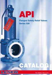
Type 526<br />
Flanged Steel Pressure Relief<br />
<strong>Valve</strong>s according to API 526<br />
Orifice D...T<br />
DESIGN FEATURES<br />
• ASME-NB certified capacities<br />
• “Single trim” for steam/gases/liquids<br />
• Versions with open and closed<br />
bonnets<br />
• Single part spindle, large guide<br />
spacings<br />
• Adjusting ring to alter the opening<br />
and reseating pressure differential<br />
(“blow-down-ring”)<br />
• Back pressure compensating stainless<br />
steel ballanced bellows available<br />
from 1 bar/15 psig [7]<br />
7<br />
18
Applications:<br />
6<br />
3 4<br />
2 1<br />
5<br />
• Large scale chemical plant<br />
– Tank protection<br />
– Blow-down systems<br />
• Oil extraction, transport and processing<br />
– Drilling platforms<br />
– Oilfields (“Christmas trees”)<br />
– Storage tank facilities<br />
– Refineries<br />
3<br />
API 526 is a purchase specification in which nominal diameters [1],<br />
flange pressure ratings [2], centre to face dimensions [3], flow areas [4],<br />
body [5] and spring materials [6], and their service limits are stipulated for<br />
“API safety valves”.<br />
API safety valves are used worldwide in the petrochemical industry, both<br />
on- and off-shore. <strong>The</strong>se applications are characterised by standardised<br />
plants, blow-down systems and long pipework sections. <strong>The</strong> capacities<br />
of API safety valves are relatively low in relation to their nominal diameters.<br />
<strong>The</strong> LESER type 526 combines the requirements of the API standards<br />
and the ASME Code with the tried and tested service reliability of the<br />
LESER product range.<br />
Section VIII Div 1<br />
- UG 125 – UG137<br />
Approval<br />
ASME B 16.5<br />
ASME-Code<br />
API<br />
Section II<br />
- SA 216, 217, 351<br />
RP 520<br />
STD 526<br />
STD 527<br />
Materials<br />
Sizing<br />
Nominal diameters<br />
Pressure ratings<br />
Orifice letters<br />
Materials<br />
Functional leak tightness<br />
ASME B 16.34<br />
Orifice<br />
letter<br />
“Orifice”<br />
E<br />
Flow area<br />
according to API 526<br />
mm 2<br />
sq.in<br />
D 71,0 0,110<br />
126 0,196<br />
Flow diameter<br />
according to API 526<br />
mm<br />
inch<br />
9,5 0,4<br />
12,7 0,5<br />
F 198 0,307<br />
15,9 0,6<br />
100<br />
Lift (%)<br />
G<br />
325 0,503<br />
H 506 0,785<br />
20,3 0,8<br />
25,4 1,0<br />
80<br />
J<br />
830 1,287<br />
32,5 1,3<br />
min.<br />
60<br />
K 1 186 1,838<br />
L<br />
1 841 2,853<br />
38,9 1,5<br />
48,4 1,9<br />
M 2 323 3,600<br />
54,4 2,1<br />
40<br />
N<br />
2 800 4,340<br />
59,7 2,4<br />
P 4 116 6,380<br />
72,4 2,8<br />
20<br />
Q<br />
7 129 11,05<br />
95,3 3,8<br />
max.<br />
0<br />
10<br />
Blowdown<br />
8 6<br />
4<br />
2<br />
Overpressure (%)<br />
0 2 4 6 8 10<br />
R 10 323 16,00<br />
T<br />
16 774 26,008<br />
114,6 4,5<br />
146,1 5,8<br />
19
Type 427/429 431/433 532/534<br />
Relief and<br />
<strong>Safety</strong> Relief <strong>Valve</strong>s<br />
with flanged connections<br />
DESIGN FEATURES<br />
• Adaptation to the relevant service<br />
conditions is ensured by:<br />
- A large range of additional<br />
accessories<br />
- Closely graded flow ratings with a<br />
wide range of nominal diameters<br />
in 11 steps<br />
(DN 15 -150 / NPS 1/2 II ...6 II )<br />
• Low overall height and low weight<br />
• <strong>The</strong> inlet nominal size is equal to the<br />
outlet nominal size<br />
100<br />
Lift (%)<br />
80<br />
60<br />
40<br />
20<br />
0<br />
Blowdown<br />
10 8 6 4<br />
2<br />
Overpressure (%)<br />
0 2 4 6 8 10<br />
100<br />
Lift (%)<br />
80<br />
60<br />
40<br />
20<br />
0<br />
Blowdown<br />
10 8 6 4<br />
2<br />
Overpressure (%)<br />
0 2 4 6 8 10<br />
1 1<br />
20
Applications:<br />
Type 431/433<br />
• Chemical industry<br />
– Production plants: low medium losses<br />
– Long pipework systems<br />
– Two phase flow<br />
– Waste gas cleaning systems (on the<br />
outlet side)<br />
• Heat transfer oil systems<br />
• Protection of liquids<br />
– Dosing/metering pumps<br />
– Hydraulic systems<br />
– Pulsating operating pressures<br />
Relief valves open in proportion to the pressure rise. <strong>The</strong>y are used wherever<br />
normally expected mass flows are very small and the medium loss<br />
is to be kept as low as possible (e.g., thermal expansion).<br />
<strong>Safety</strong> relief valves are ideal relief valves for medium mass flows. <strong>The</strong>ir<br />
large proportional range leads to consistent functioning and relief of pressure<br />
peaks, particularly with liquids. Both proportional and safety relief<br />
valves are characterised by particularly stable operation.<br />
<strong>The</strong>re are four series available:<br />
Type 431/433:<br />
<strong>Safety</strong> relief valve spring loaded [1], cast const<strong>ru</strong>ction<br />
with flanged connections for nominal pressure ratings up to<br />
PN 40/PR #150;<br />
three body materials: stainless steel, carbon steel and nodular<br />
cast iron<br />
• Mechanical engineering (OEM)<br />
– Reciprocating compressors of small and<br />
medium capacities<br />
Type 427/429 532/534<br />
• Overflow functions<br />
• <strong>The</strong>rmal expansion<br />
– Protection of pipeline segments<br />
– Enclosed storage tanks<br />
<strong>Safety</strong> relief valve spring loaded, cast const<strong>ru</strong>ction<br />
with flanged connections for nominal pressure ratings up to<br />
PN 160/PR #600;<br />
two body materials: stainless steel and cast carbon steel<br />
Type 427/429:<br />
Relief valve spring loaded [1], cast const<strong>ru</strong>ction<br />
with flanged connections; three body materials:<br />
stainless steel, carbon steel and nodular cast iron<br />
Type 532/534:<br />
In-line relief valve spring loaded, cast const<strong>ru</strong>ction<br />
with flanged connections and in-line design [2];<br />
two body materials: carbon steel and cast iron<br />
Type Bonnet Flange<br />
DIN 2501<br />
Flange<br />
ASME B 16.5<br />
Form Opening<br />
characteristic<br />
PN DN PR NPS (S/G)<br />
431<br />
433<br />
open<br />
closed<br />
16...40 15...150 #150 1<br />
/2 ıı ...6 ıı<br />
63...160 15, 25 #300... #600 1<br />
/2 ıı ...1 ıı<br />
Angle type<br />
<strong>Safety</strong> relief<br />
427<br />
429<br />
open<br />
closed<br />
2 2<br />
532<br />
534<br />
open<br />
closed<br />
16...40 15...150 #150<br />
1<br />
/2 ıı ...6 ıı Relief<br />
16...40 15...150 #150<br />
1<br />
/2 ıı ...6 ıı<br />
In-line<br />
21
Type 437/438/439 459/462<br />
<strong>Safety</strong> <strong>Valve</strong>s<br />
with threaded connections<br />
DESIGN FEATURES<br />
• Maintenance friendly with screwed<br />
in nozzle [1] [2] and detachable<br />
lifting aid [5]<br />
• Universal application through metal<br />
sealing of all body parts<br />
• Variety of connections through:<br />
– Threaded connection:<br />
• Connections according to<br />
DIN ISO 228, NPT or customer<br />
requests<br />
• Available as male or female thread<br />
in parallel or taper design<br />
– Flanged connection:<br />
• Flanges according to DIN, ANSI,<br />
IG or special design<br />
• Inlet: Slip on flange design [7]<br />
• Complete draining of the valve<br />
chamber<br />
• Short delivery times, even for<br />
special materials<br />
Type 437/438/439<br />
• Extremely compact design<br />
• Disc with changeable sealing<br />
plate [3], materials: PTFE-carbon,<br />
PCTFE or on request<br />
• Attractive design, machined on all<br />
sides<br />
• Certified for horizontal fitting<br />
• Type 438: Soft seal disc [6]<br />
• Type 439: Rubber sealing surface,<br />
low pressure application [3]<br />
Type 459/462<br />
• Smallest available safety valve with<br />
bellows [4]<br />
• Smooth surfaces, deep drawn body<br />
and bonnet<br />
• For p >250 bar g/3625 psig stellited<br />
sealing surfaces (seat/disc)<br />
• Type 462: Soft seal disc [6]<br />
22
Applications:<br />
• Carbon dioxide plants<br />
– Manufacture<br />
– Vaporisation<br />
– Processing<br />
• Technical gases<br />
– Air separation (cold box)<br />
– Cylinder filling<br />
• Refrigeration systems<br />
– 3K helium systems<br />
• Compressors<br />
– Diving air<br />
– Low, medium and high pressure systems<br />
<strong>Safety</strong> valves with threaded connections are used for handling small<br />
and medium mass flows.<br />
<strong>The</strong> LESER threaded connection safety valves are notable for their wide<br />
range of set pressures, compact overall dimensions and low weight.<br />
<strong>The</strong>re are two series available:<br />
Type 437/438/439<br />
<strong>Safety</strong> relief valve spring loaded [1] for small mass flows<br />
(e.g., thermal expansion and overflow);<br />
two body materials: chrome steel or stainless steel<br />
Type 459/462<br />
Full lift safety valve spring loaded [2] for the medium mass flow<br />
range (e.g., small scale or pilot plant);<br />
two body materials: stainless steel or chrome steel/nodular cast<br />
iron<br />
• Steam generators<br />
– Flash steam generators<br />
– Firetube boilers<br />
• LPG/LNG<br />
– Terminals<br />
– Carriers<br />
• Pumps<br />
– Dosing/metering pumps<br />
– Overflow protection<br />
• Pipework protection<br />
– Pipelines<br />
– Chemical plants<br />
• Chemical installations<br />
– Technical centres<br />
– Reactors<br />
1 2 3<br />
4 5 6 7<br />
Type<br />
437<br />
438<br />
439<br />
Inlet<br />
male<br />
Set pressure range<br />
(bar)<br />
(psig)<br />
1<br />
/2 ıı 0,1...330 1,5...4785<br />
Characteristic<br />
Metal seal<br />
1<br />
/2 ıı 0,5...180 7,5...2610 Soft seal<br />
1<br />
/2 ıı 0,1...16 1,5...232 Rubber sealing surface<br />
459<br />
459M<br />
3<br />
/4 ıı ...1 ıı<br />
1<br />
/2 ıı<br />
0,1...250<br />
250...700<br />
1,5...3625<br />
3625...10150<br />
Metal seal<br />
machined from solid<br />
462 3<br />
/4 ıı ...1 ıı 0,1...250 1,5...3625 Soft seal<br />
23
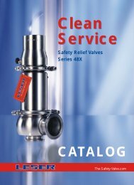
Type 481 483 484 485 486 488<br />
<strong>Safety</strong> <strong>Valve</strong>s<br />
for “Clean Service”<br />
DESIGN FEATURES<br />
• Many aseptic connections possible<br />
(e.g., dairy industry coupling, sterile<br />
screw coupling, small flange, Triclamps)<br />
• FDA-compliant elastomer materials<br />
• Excellent cleanability and sterilization<br />
through:<br />
– Crevice free fastening of all<br />
elastomer parts [4]<br />
– Exposed, rinsed o-rings<br />
– Outlet chamber sealed from<br />
bonnet by EPDM bellows [4]<br />
• Body and trim in material<br />
1.4404/1.4435/316L; other materials<br />
on request<br />
• Manual lifting device H4 or pneumatic<br />
lifting device H8 as options [5]<br />
• Control of operating conditions<br />
open/closed via indicator<br />
1 4<br />
2 5<br />
3 6<br />
24
486<br />
25,40,50,65, 80<br />
Reduced dead space, Free discharge,<br />
0,1...16 1,5...232 very high (G – P)<br />
1 1 /2 ıı ,2 ıı ,2 1 /2 ıı ,3 ıı ,4 ıı Applications:<br />
Type 481<br />
• Pipelines<br />
• Autoclaves<br />
• Food industry<br />
• Breweries<br />
LESER has developed five safety valve types, known collectively as the<br />
“48x series”, for the protection of systems with special cleanliness requirements<br />
Type 484<br />
(“clean service”: systems for foodstuffs, beverages, pharma-<br />
ceuticals and cosmetics). <strong>The</strong> properties common to the “48x series” are:<br />
• Low dead space<br />
•<br />
•<br />
Fermenters<br />
Bio-reactors<br />
• High surface quality<br />
• Free of crevice<br />
Type 485<br />
• CIP, SIP, and COP capability<br />
<strong>The</strong> six types differ in capacities and opening characteristics:<br />
Type 481: <strong>Safety</strong> relief valve for small capacity<br />
Type 483: <strong>Safety</strong> relief valve for small and medium capacity [1]<br />
Type 486: High capacity safety relief valve for liquids<br />
Type 488: Full lift safety valve for large capacity for air, steam, liquid<br />
For the very highest aseptic requirements, dead-space-free special<br />
designs for direct installation are also available:<br />
Type 484: <strong>Safety</strong> relief valve with connection direct to vessel [2]<br />
Type 485: <strong>Safety</strong> relief valve with integrated pipework connection [3]<br />
<strong>The</strong> safety valves of the “48x” series can be fitted with manually lockable<br />
lifting devices H4 to hold open at a small lift, and with pneumatic lifting<br />
devices H8 for automated systems (CIP process) [6].<br />
Type DN<br />
NPS<br />
Set pressure range Output Aseptic properties<br />
(bar) (psig) “Orifice”<br />
Inlet Outlet<br />
481<br />
25<br />
Low dead space,<br />
0,1...68 1,5...986 low (D – E)<br />
1 ıı<br />
crevice free<br />
Free discharge<br />
483<br />
25, 40<br />
Low dead space, Free discharge,<br />
0,1...16 1,5...232 medium (F – J)<br />
1 ıı ,1 1 /2 ıı<br />
crevice free crevice free, no dome<br />
484<br />
25, 40<br />
Dead space free, Free discharge,<br />
0,1...16 1,5...232 medium (F – J)<br />
1 ıı ,1 1 /2 ıı<br />
crevice free crevice free, no dome<br />
485<br />
15, 25, 40, 50<br />
Dead space free, Free discharge,<br />
0,1...16 1,5...232 medium (F – J)<br />
crevice free crevice free, no dome<br />
488<br />
• Stainless steel reactors /vessels<br />
Type 483, 486, 488<br />
• Laboratory facilities<br />
• Beverage industry<br />
– Bottling plants (mixers, fillers)<br />
– Storage tanks<br />
• Pipework protection if direct vessel<br />
protection is impossible or not desired<br />
1<br />
/2 ıı ,1 ıı ,1 1 /2 ıı ,2 ıı crevice free crevice free, no dome<br />
25...100<br />
Reduced dead space, Free discharge,<br />
0,2...16 3,0...232 very high (K – P)<br />
1 ıı ...4 ıı<br />
crevice free crevice free, no dome<br />
25
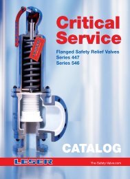
Type 447 546 449<br />
<strong>Safety</strong> <strong>Valve</strong>s for<br />
critical service conditions<br />
DESIGN FEATURES<br />
Type 546:<br />
• Body:<br />
carbon steel or nodular cast iron<br />
• Nozzle: stabilised by support ring [1],<br />
optionally in<br />
– PTFE<br />
– PTFE - carbon<br />
• Bellows: optionally<br />
– PTFE bellows<br />
– Stainless steel bellows<br />
• Sealing element: sealing disc in<br />
– Borofloat - glass<br />
(thermal shock resistant)<br />
– PTFE - carbon<br />
Type 447:<br />
• Body: cast steel, lined<br />
• Lining: vacuum-proof, isostatic lining<br />
in virgin PTFE [2]<br />
• Seat nozzle: PTFE/glass sintered<br />
under inert gas<br />
• Nozzle, sealing disc and inlet body<br />
[3] can be replaced separately and<br />
are available in special materials for<br />
specific applications<br />
Type 449:<br />
• Block body: Manufactured from a<br />
single block, material 1.4571 or special<br />
materials such as Hastelloy<br />
4<br />
26
Applications:<br />
Type 546<br />
• Multiple product systems<br />
Type 447<br />
• Chlorine manufacture and processing<br />
• Reducing acids<br />
(e.g., hydrochloric acid, acetic acid)<br />
• Alkalis<br />
(e.g., NaOH solution)<br />
Type 449<br />
In chemical plants critical service conditions and media may occur<br />
which place special demands on the design of safety valves, e.g.,<br />
• Highly corrosive media • Highly toxic media • High back pressures<br />
LESER has developed three series of safety valves for these applications:<br />
• Phosgene systems<br />
• MDI systems<br />
Type 546:<br />
<strong>Safety</strong> valve with PTFE nozzle and protective coating in the outlet area for<br />
protection from highly corrosive media in systems with relatively rare activation<br />
of the safety valve. <strong>The</strong> PTFE nozzle avoids product contam-ination<br />
and adherence. By implementing stainless steel bellows operation<br />
with up to 50% back pressure is possible.<br />
Type 447:<br />
<strong>Safety</strong> valve with full PTFE lining for protection from highly corrosive<br />
media. <strong>The</strong> PTFE bellows is gastight and back-pressure compensated.<br />
Adherence is avoided by the smooth PTFE surfaces. (max. R z 16 µm).<br />
Type 449:<br />
<strong>Safety</strong> valve in block form for protection from highly toxic media. A duct<br />
system for inert gas shrouding and analysis prevents the medium from<br />
getting into the atmosphere [4].<br />
min.<br />
3 mm<br />
1 2 3<br />
Type<br />
546<br />
447<br />
449<br />
Set pressure<br />
range<br />
(bar) (psig)<br />
0,1...10 1,5...145<br />
0,1...16 1,5...232<br />
0,1...16 1,5...232<br />
Flange<br />
DIN 2501<br />
Flange<br />
ASME B 16.5<br />
PN DN PR NPS<br />
16...40 25...100 #150 1 ıı ...4 ıı<br />
16 25...100 #150 1 ıı ...4 ıı<br />
16...40 25, 50, 80 #150... #300 1 ıı ,2 ıı ,3 ıı<br />
27
Type 411 421 522 543/544 440 424 450 460<br />
<strong>Safety</strong> <strong>Valve</strong>s according<br />
to special standards<br />
and regulations<br />
DESIGN FEATURES<br />
Type 411 421 522:<br />
• Low overall height<br />
• Direct lifting<br />
• Simple adjustment of set pressure<br />
• Hardened edge guides<br />
Type 543 544:<br />
• Two independently functioning safety<br />
valves<br />
• Common vessel connector<br />
• Common discharge pipe<br />
Type 440 460 and 424 450:<br />
• Fixed set pressure steps in the range<br />
of 0,5 .... 10 bar<br />
• Elastomer bellows to protect the<br />
sliding parts<br />
• Soft sealing o-ring disc<br />
1<br />
2<br />
3<br />
28
<strong>The</strong>re are special <strong>ru</strong>les and regulations in many countries for the protection<br />
of land-based steam boilers, marine steam boilers and heating<br />
systems. <strong>The</strong>se specifications are fulfilled by LESER’s special series:<br />
<strong>Safety</strong> valves with lever and weight (Types 411 421 522) [1]:<br />
<strong>The</strong> main application for safety valves with levers and weights is<br />
the protection of land-based steam boilers. Further applications<br />
result from their small overall height and the ease of set pressure<br />
adjustment.<br />
Double safety valves (Types 543/544) [2]:<br />
Two independent safety valves – in some cases with a government<br />
ring – are specified for the protection of ship’s boilers. In<br />
the constricted space on ships double safety valves fulfil this<br />
requirement ideally with only one connector on the steam<br />
boiler.<br />
<strong>Safety</strong> valves for heating plants,<br />
low pressure steam boilers (Types 424 440 450 460) [3]:<br />
For heating plants up to 120 °C and low pressure steam boilers<br />
up to 1 bar TRD 721 requires safety valves with soft sealing and<br />
elastomer bellows to protect the sliding parts.<br />
Type Bonnet Flange Flange Main characteristic<br />
DIN 2501 ASME B 16.5<br />
PN DN PR NPS<br />
411 – 16...40 20...150 #150 3<br />
/4 ıı ...6 ıı <strong>Safety</strong> relief valve with lever<br />
421 – 16...40 25...100 #150 1 ıı ...4 ıı Full lift safety valve with lever<br />
522 – 40 50...100 #150 2 ıı ...4 ıı Double safety relief valve with lever<br />
543<br />
544<br />
open<br />
closed<br />
40 50...100 #150<br />
2 ıı ...4 ıı Double safety relief valve spring loaded<br />
440<br />
closed with<br />
bore<br />
16 20...150 – –<br />
<strong>Safety</strong> valve<br />
according to TRD 721 section 6<br />
424<br />
closed with<br />
bore<br />
16 25...150 – –<br />
<strong>Safety</strong> valve<br />
according to TRD 721 section 5<br />
460<br />
450<br />
closed with<br />
bore<br />
closed with<br />
bore<br />
– 15, 20 – G 3 /4 ıı ,G1 ıı <strong>Safety</strong> valve according to<br />
TRD 721 section 6, threaded connections<br />
– 15, 20 – G 3 /4 ıı ,G1 ıı <strong>Safety</strong> valve according to<br />
TRD 721 section 5, threaded connections<br />
29
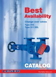
Type 310 311<br />
Change-over <strong>Valve</strong>s<br />
DESIGN FEATURES<br />
• Compact, low weight design<br />
• Full flow area on change-over<br />
• Flow area designed in such a way<br />
that no flow constriction takes place,<br />
and drag coefficients of resistance<br />
are therefore low:<br />
– Type 310 = 0.6...1.0<br />
– Type 311 = 1.0...2.0<br />
• Conical seal surfaces increase functional<br />
leak tightness<br />
• Optionally available with stuffing box<br />
or stainless steel bellows with safety<br />
stuffing box<br />
Type 310:<br />
• Two body materials: cast steel and<br />
cast stainless steel<br />
• Can be combined with safety valves<br />
of the same nominal diameter [2]<br />
Type 311:<br />
• Two body materials: steel and stainless<br />
steel<br />
• Reducers can be directly welded on<br />
Options:<br />
– Pressure relief valve<br />
– Bypass with non-return valves<br />
– Limit switches<br />
30
Applications:<br />
• Continuously functioning plant<br />
– Bitumen refineries<br />
– Oilfields<br />
– Ethylene plants<br />
• Non-drainable systems<br />
– Natural gas caverns, large storage facilities<br />
– Storage tanks for technical gases (e.g.,<br />
ethylene reservoirs)<br />
• Application required by national standards<br />
– TRB 801 Nr. 14 for refrigeration systems<br />
– TRB 801 Nr. 26 for technical gases below<br />
-10°C<br />
– TRB 801 Nr. 27 for liquid gas systems<br />
Change-over valves will be used if a plant shutdown is impossible or<br />
undesirable for process engineering or commercial reasons. With<br />
change-over valves it is possible to switch over between parallel safety<br />
valves without inter<strong>ru</strong>pting operation, so as, for example, to perform<br />
maintenance work.<br />
<strong>The</strong> design of the change-over valves ensures:<br />
• Low pressure losses on discharge flow (3% criterion)<br />
• Adequate open passage in any position during the changeover<br />
process<br />
• Stable operation of the downstream safety valves<br />
<strong>The</strong> combination [2] of LESER change-over valves and safety valves has<br />
been comprehensively tested on full flow test labs.<br />
<strong>The</strong>re are two series available:<br />
Type 310: cast const<strong>ru</strong>ction DN 25...150/NPS 1 || ...6 || [1]<br />
Type 311: welded const<strong>ru</strong>ction DN 80... 400/ NPS 3 || ...16 ||<br />
1 2<br />
Type<br />
310<br />
311<br />
Flange<br />
DIN 2501<br />
Flange<br />
ASME B 16.5<br />
PN DN PR NPS<br />
40...160 25...150 #150... #600 1 ıı ...6 ıı<br />
10...160 80...400 #150... #600 3 ıı ...16 ıı<br />
Main<br />
characteristic<br />
Cast const<strong>ru</strong>ction<br />
Welded const<strong>ru</strong>ction<br />
31
Type 700<br />
“Supplementary Loading”<br />
System<br />
DESIGN FEATURES<br />
Control Unit<br />
• Redundant design of the sensing<br />
and control systems<br />
• Individual testing of the control<br />
systems during operation is possible<br />
• Protection category IP 54 or 68<br />
• Low control air consumption<br />
• Remote activation from the control<br />
panel possible<br />
• Service range from -30°C to +60°C<br />
(-30°C to +2°C additional heater<br />
required)<br />
• Quick coupling measuring points for<br />
pressure diagnosis<br />
Actuators<br />
• Robust, simple design (in three sizes)<br />
• Coupling design also suitable for<br />
safety valves of other manufacturers<br />
• Non-interchangeable connections for<br />
loading air and lifting air<br />
<strong>Valve</strong> lift actuator<br />
• Operation of up to 6 safety valves<br />
from one control unit possible<br />
32
Applications:<br />
• Large steam boilers in power stations<br />
• Industrial heating boilers:<br />
– High system availability and greatest<br />
possible use of the maximum allowable<br />
working pressure<br />
– Paper mills<br />
– Chemical industry<br />
– Sugar factories<br />
LESER safety valves can be equipped with a supplementary loading<br />
system. <strong>The</strong> supplementary loading system consists of four components:<br />
• <strong>Safety</strong> valve<br />
• Actuator<br />
• Control units (pneumatic, electric/pneumatic)<br />
• <strong>Valve</strong> lift actuator<br />
<strong>The</strong> supplementary loading system (ZB) allows the system operating<br />
pressure to be increased (∆p+) to just below the set pressure of the<br />
safety valve (SV). <strong>The</strong> functional leak tightness of the additionally loaded<br />
safety valve is ensured up to the set pressure (anti-simmer device). When<br />
the safety valve operates the supplementary loading device assists the<br />
opening [2] and closing [1] processes, thus returning the system to its<br />
original service condition more rapidly. As a result the blow-off process is<br />
shortened and the product losses are smaller.<br />
pressure p<br />
Set pressure<br />
Operating pressure ZB<br />
Operating pressure SV<br />
∆ p+<br />
1 2 1<br />
Blow-down ZB<br />
Blow-down SV<br />
t failure ZB<br />
t failure SV<br />
time t<br />
1 2<br />
loaded<br />
open<br />
33
34<br />
Options<br />
Highest adaptation to<br />
all service conditions
1<br />
2<br />
3<br />
<strong>The</strong> stainless steel bellows [1] have two functions:<br />
- Compensation of applied or built-up back pressure on the outlet side of<br />
the valve. <strong>The</strong> full lift of the safety valve is thus ensured.<br />
-Protection of the sliding parts and springs from temperature or cotamination.<br />
<strong>The</strong> lift stop [2], e. g., by gag, serves to adjust the safety valve precisely<br />
to the mass flow to be discharged.<br />
<strong>The</strong> Test Gag [3] allows the valve to be blocked for pressure tests on the<br />
system.<br />
<strong>The</strong> vibration damper [4] suppresses vibrations on safety valves even<br />
under extremely adverse system conditions. A stable blow-off is ensured.<br />
<strong>The</strong> safety valve/bursting disc combination [5] is used, where environmentally<br />
harmful, toxic or expensive media or media with a propensity to<br />
adhere are protected, and at the same time the highest demands are<br />
placed on freedom from leakage. <strong>The</strong> safety valve and bursting disc combination<br />
are type tested.<br />
<strong>The</strong> drain hole [6] serves to drain the valve body, particularly in the<br />
presence of condensate in the case of steam plants.<br />
Flanges, flange sealing faces, threaded or special connections can<br />
be supplied to European, American and other standards.<br />
In systems which have to be heated (e.g., protection of freezing media or<br />
viscous media) the safety valve can be fitted with a heating jacket [7].<br />
<strong>The</strong> heating jacket is heated either by low pressure steam or by heat<br />
transfer oils.<br />
<strong>Safety</strong> valve seat and disc:<br />
- Metal sealing: seat and hardened disc have precision machined sealing<br />
faces. For severe service conditions stelliting of the sealing faces is<br />
available.<br />
- Soft sealing: discs with soft seals (o-rings) offer high degrees of leakproofness.<br />
A large number of elastomers are available for selection. <strong>The</strong><br />
temperature limits of the elastomers must be observed (min. -45 °C/<br />
max. 250 °C).<br />
4<br />
5<br />
6<br />
7<br />
35
Flanged connections<br />
Inlet<br />
Type DIN 2501 ASME B16.5 Max. set pressure<br />
Bonnet<br />
Bonnet<br />
open closed DN PN NPS PR [bar g] [psig]<br />
Full Lift <strong>Safety</strong> <strong>Valve</strong>s with flanged connections – up to PN 40/PR #300 (Page 14)<br />
442 441 20···200 16···40 – – 40 580<br />
442 441 – – 1"···4" #150 ···#300 50 740<br />
442 441 200···400 10···25 8"···16" #150···#300 25 362<br />
<strong>Safety</strong> <strong>Valve</strong>s for high operating pressures – ≥ PN 63/PR #600 (Page 16)<br />
455 456 25···100 63···160 – – 100 1450<br />
457 458 25···150 63···400 1"···6" #300···#2500 400 5800<br />
– 459M 10 63···700 1<br />
/2" #300···#2500 700 10150<br />
Flanged Steel Pressure Relief <strong>Valve</strong>s according to API 526 Orifice D...T (Page 18)<br />
526 526 – – 1"···6" #150···#2500 414 6000<br />
Relief and <strong>Safety</strong> Relief <strong>Valve</strong>s with flanged connections (Page 20)<br />
427 429 15···150 16···40 1<br />
/2"···6" #150 40 580<br />
431 433 15···150 16···40 1<br />
/2"···6" #150 40 580<br />
431 433 15, 25 63···160 1<br />
/2"···1" #300···#600 160 2320<br />
532 534 15···150 16···40 1<br />
/2"···6" #150 40 580<br />
<strong>Safety</strong> <strong>Valve</strong>s with threaded connections (Page 22)<br />
– 437 10, 15 – 1<br />
/2" – 330 4785<br />
– 438 10, 15 – 1<br />
/2" – 180 2610<br />
– 439 10, 15 – 1<br />
/2" – 16 232<br />
– 459 10···20 – 1<br />
/2"···1" – 250 3625<br />
– 459M 10 – 1<br />
/2" – 700 10150<br />
– 462 15, 20 – 1<br />
/2"···1" – 250 3625<br />
<strong>Safety</strong> <strong>Valve</strong>s for “Clean Service” (Page 24)<br />
– 481 25 1" 68 986<br />
– 483 25, 40 1", 1 1 /2" 16 232<br />
– 484 25, 40<br />
Aseptic<br />
Aseptic<br />
connections<br />
1", 1 1 /2"<br />
connections<br />
16 232<br />
– 485 15, 25, 40, 50<br />
on request<br />
1<br />
/2", 1", 1 1 /2", 2"<br />
on request<br />
16 232<br />
– 486 25, 40, 50 65, 80 1 1 /2, 2", 2 1 /2", 3", 4" 16 232<br />
– 488 25···100 1"···4" 16 232<br />
<strong>Safety</strong> <strong>Valve</strong>s for critical service conditions (Page 26)<br />
– 546 25···100 16···40 1"···4" #150 10 145<br />
– 447 25···100 16 1"···4" #150 16 232<br />
– 449 25, 50, 80 16···40 1", 2", 3" #150···#300 16 232<br />
<strong>Safety</strong> <strong>Valve</strong>s according to special standards and regulations (Page 28)<br />
411 20···150 16···40 3<br />
/4"···6" #150 40 580<br />
421 25···100 16···40 1"···4" #150 40 580<br />
522 50···100 40 2"···4" #150 40 580<br />
543 544 50···100 40 2"···4" #150 40 580<br />
– 440 20···150 16 – – 10 –<br />
– 424 25···150 16 – – 0,5 + 1,0 –<br />
– 450 15, 20 – G3/4", G1 II – 10 –<br />
– 460 15, 20 – G3/4", G1 II – 0,5 + 1,0 –<br />
Change-over <strong>Valve</strong>s (Page 30)<br />
310 25···150 40···160 1"···6" #150···#600 – –<br />
311 80···400 10···160 3"···16" #150···#600 – –<br />
Pressure Reducing <strong>Valve</strong> for Steam<br />
612 15···100 16, 40 1/2"···4" #150 25 Upstream pressure 362 Upstream pressure<br />
“Supplementary Loading” System (Page 32)<br />
700 For detailed information on characteristics and function see complete catalogue section 14<br />
Footnotes<br />
Opening characteristic for Steam/Gas (D/G)<br />
1<br />
) 1.4571/SA-240/SA-479 316Ti (according to AD-Merkblatt A2, TRD 421 and TRD 721)<br />
2<br />
) 1.4581/SA-351 CF10M Full Lift <strong>Safety</strong> <strong>Valve</strong> V<br />
<strong>Safety</strong> Relief <strong>Valve</strong><br />
N<br />
Relief <strong>Valve</strong><br />
P<br />
<strong>Safety</strong> <strong>Valve</strong> for Hot Water<br />
Heating plants up to 120 °C H<br />
36
Body materials<br />
Opening Complete<br />
0.6025 0.7043/ 1.0619/ 1.7357/ 1.0460/ 1.4104/ 1.4404/ 1.4408/ characteristic catalogue<br />
SA-365 SA-216 WCB SA-217 WC6 1.0425 AISI 430F SA240/ SA-351 CF8M Main characteristic S/G<br />
60-40-18 Carbon steel SA-479 316L<br />
CI NCI GS/carbon steel corrosion resistant/ see below Page<br />
low temperature ductile<br />
..<br />
x x x x Cast const<strong>ru</strong>ction with DIN flanges V 4/11<br />
x x Cast const<strong>ru</strong>ction with ANSI-flanges V 4/15<br />
x x x 1) Welded const<strong>ru</strong>ction V 4/20<br />
x x 2) Semi nozzle V 4/40<br />
x x x x Full nozzle V 4/50<br />
x Machined from solid V 9/20<br />
x x x <strong>Safety</strong> valves to API 526 Orifice D...T V 5/10<br />
x x x x Relief valve P 7/10<br />
x x x x <strong>Safety</strong> relief valve N 6/10<br />
x x High pressure safety relief valve N 6/20<br />
x x In-line design P 7/20<br />
x x Metal seal N 9/10<br />
x x Soft seal, horizontal installation N 9/12<br />
x x Rubber sealing surface N 9/14<br />
x x Metal seal V 9/20<br />
x Machined from solid V 9/25<br />
x x O-Ring soft seal V 9/22<br />
x Low dead space small valve N 12/10<br />
x Low dead space safety relief valve N 12/20<br />
x Dead space free, connection direct to vessel N 12/40<br />
x Dead space free, integrated pipework connection N 12/50<br />
x High capacity relief valve for liquids N 12/60<br />
x Low dead space full lift safety valve V 12/30<br />
x x PTFE nozzle N 11/10<br />
x Fully PTFE lined N 11/20<br />
x <strong>Safety</strong> valve in block form with inert gas shrouding N 11/30<br />
x x <strong>Safety</strong> relief valve with lever N 8/10<br />
x x Full lift safety valve with lever V 8/20<br />
x Double safety relief valve with lever N 8/30<br />
x Double safety valve spring loaded N 6/30<br />
x SV according to TRD 721 section 6, flanged connection H 10/10<br />
x SV according to TRD 721 section 5, flanged connection V 10/20<br />
x SV according to TRD 721 section 6, threaded connection H 10/40<br />
x SV according to TRD 721 section 5, threaded connection V 10/30<br />
x x Cast const<strong>ru</strong>ction – 16/10<br />
x x 1) Welded const<strong>ru</strong>ction – 16/30<br />
x x – 17/10<br />
Redundant control unit – 14/10<br />
37
Imprint<br />
LESER GmbH & Co. KG<br />
Wendenstr. 133-135<br />
D-20537 Hamburg<br />
P.O.Box 26 16 51<br />
D-20506 Hamburg<br />
Fon +49 (40) 251 65-100<br />
Fax +49 (40) 251 65-500<br />
E-Mail: sales@leser.com<br />
www.leser.com<br />
Coordination:<br />
Ralf Dankert, Christine Sammann<br />
Design and production:<br />
IMAGEKONTOR<br />
Grosse Johannisstrasse 15<br />
D-20457 Hamburg<br />
Fon +49 (40) 298 340 04<br />
Fax +49 (40) 298 32 20<br />
Photography:<br />
Ullrich Nürnberg<br />
Eppendorfer Markt 14<br />
D-20251 Hamburg<br />
Fon +49 (40) 46 881 355<br />
Fax +49 (40) 46 881 356<br />
Aerial photograph S. 9 M. Schulze-Alex<br />
Printing:<br />
Hartung D<strong>ru</strong>ck + Medien GmbH<br />
Asbrookdamm 38<br />
D-22115 Hamburg<br />
Fon +49 (40) 23 70 06-40<br />
Fax +49 (40) 23 70 06-30<br />
Application samples (page 14 – 35) with friendly<br />
support of: Aventis Production Technologies GmbH,<br />
Frankfurt; Deutsche Shell AG, Hamburg; Dickow<br />
Pumpen KG, Waldkraiburg; GEA Tuchenhagen GmbH,<br />
Büchen; Hamburg Südamerikanische Dampfschifffahrtsgesellschaft<br />
Amsinck & Eggert, Hamburg; HEW<br />
AG, Heizkraftwerk Tiefstack, Hamburg; K<strong>ru</strong>pp Uhde<br />
GmbH, Dortmund; Leuna Werke GmbH, Leuna; Linde<br />
AG, Werksg<strong>ru</strong>ppe Technische Gase, Höllriegelskreuth;<br />
Max Weishaupt GmbH, Schwendi; Schering AG, Bergkamen;<br />
MV Rugenberger Damm, Hamburg.<br />
LWN 505.01-505.40 / 5 th edition 2004 - 5000<br />
39
<strong>The</strong> <strong>Safety</strong> <strong>Valve</strong><br />
LESER GmbH & Co. KG D-20537 Hamburg, Wendenstr. 133-135<br />
D-20506 Hamburg, P.O.Box 26 16 51<br />
Fon +49 (40) 251 65-100<br />
Fax +49 (40) 251 65-500<br />
E-Mail: sales@leser.com<br />
www.leser.com