16-Channel, Constant-Current LED Driver with LED Open Detection
16-Channel, Constant-Current LED Driver with LED Open Detection
16-Channel, Constant-Current LED Driver with LED Open Detection

Create successful ePaper yourself
Turn your PDF publications into a flip-book with our unique Google optimized e-Paper software.
TLC5928<br />
www.ti.com ................................................................................................................................................. SBVS120A–JULY 2008–REVISED SEPTEMBER 2008<br />
DETAI<strong>LED</strong> DESCRIPTION<br />
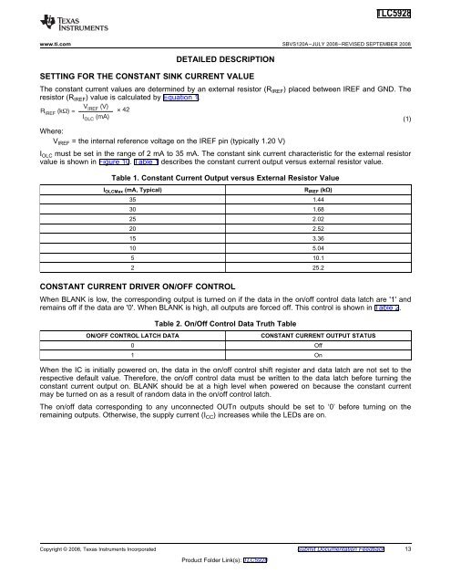
SETTING FOR THE CONSTANT SINK CURRENT VALUE<br />
The constant current values are determined by an external resistor (R IREF ) placed between IREF and GND. The<br />
resistor (R IREF ) value is calculated by Equation 1.<br />
V IREF (V)<br />
R IREF (k ) =<br />
42<br />
I<br />
OLC<br />
(mA)<br />
(1)<br />
Where:<br />
V IREF = the internal reference voltage on the IREF pin (typically 1.20 V)<br />
I OLC must be set in the range of 2 mA to 35 mA. The constant sink current characteristic for the external resistor<br />
value is shown in Figure 10. Table 1 describes the constant current output versus external resistor value.<br />
Table 1. <strong>Constant</strong> <strong>Current</strong> Output versus External Resistor Value<br />
I OLCMax (mA, Typical)<br />
CONSTANT CURRENT DRIVER ON/OFF CONTROL<br />
R IREF (kΩ)<br />
35 1.44<br />
30 1.68<br />
25 2.02<br />
20 2.52<br />
15 3.36<br />
10 5.04<br />
5 10.1<br />
2 25.2<br />
When BLANK is low, the corresponding output is turned on if the data in the on/off control data latch are '1' and<br />
remains off if the data are '0'. When BLANK is high, all outputs are forced off. This control is shown in Table 2.<br />
ON/OFF CONTROL LATCH DATA<br />
Table 2. On/Off Control Data Truth Table<br />
CONSTANT CURRENT OUTPUT STATUS<br />
0 Off<br />
1 On<br />
When the IC is initially powered on, the data in the on/off control shift register and data latch are not set to the<br />
respective default value. Therefore, the on/off control data must be written to the data latch before turning the<br />
constant current output on. BLANK should be at a high level when powered on because the constant current<br />
may be turned on as a result of random data in the on/off control latch.<br />
The on/off data corresponding to any unconnected OUTn outputs should be set to ‘0’ before turning on the<br />
remaining outputs. Otherwise, the supply current (I CC ) increases while the <strong>LED</strong>s are on.<br />
Copyright © 2008, Texas Instruments Incorporated Submit Documentation Feedback 13<br />
Product Folder Link(s): TLC5928