16-Channel, Constant-Current LED Driver with LED Open Detection
16-Channel, Constant-Current LED Driver with LED Open Detection
16-Channel, Constant-Current LED Driver with LED Open Detection

You also want an ePaper? Increase the reach of your titles
YUMPU automatically turns print PDFs into web optimized ePapers that Google loves.
TLC5928<br />
www.ti.com ................................................................................................................................................. SBVS120A–JULY 2008–REVISED SEPTEMBER 2008<br />
STATUS INFORMATION DATA (SID)<br />
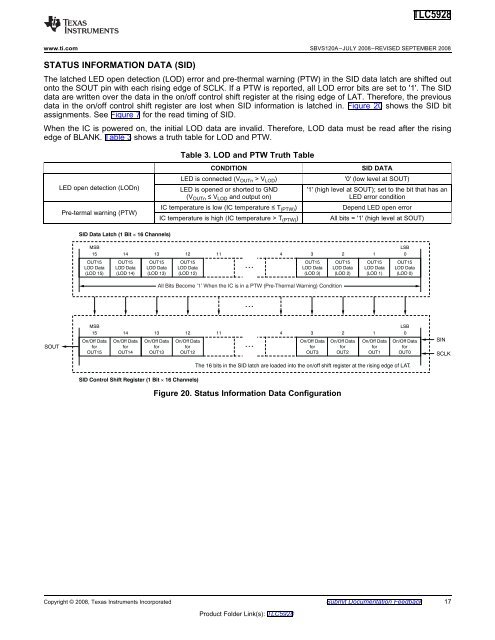
The latched <strong>LED</strong> open detection (LOD) error and pre-thermal warning (PTW) in the SID data latch are shifted out<br />
onto the SOUT pin <strong>with</strong> each rising edge of SCLK. If a PTW is reported, all LOD error bits are set to '1'. The SID<br />
data are written over the data in the on/off control shift register at the rising edge of LAT. Therefore, the previous<br />
data in the on/off control shift register are lost when SID information is latched in. Figure 20 shows the SID bit<br />
assignments. See Figure 7 for the read timing of SID.<br />
When the IC is powered on, the initial LOD data are invalid. Therefore, LOD data must be read after the rising<br />
edge of BLANK. Table 3 shows a truth table for LOD and PTW.<br />
SID Data Latch (1 Bit <strong>16</strong> <strong>Channel</strong>s)<br />
Table 3. LOD and PTW Truth Table<br />
CONDITION<br />
<strong>LED</strong> is connected (V OUTn > V LOD )<br />
SID DATA<br />
'0' (low level at SOUT)<br />
<strong>LED</strong> open detection (LODn) <strong>LED</strong> is opened or shorted to GND '1' (high level at SOUT); set to the bit that has an<br />
(V OUTn ≤ V LOD and output on) <strong>LED</strong> error condition<br />
Pre-termal warning (PTW)<br />
IC temperature is low (IC temperature ≤ T (PTW) )<br />
IC temperature is high (IC temperature > T (PTW) )<br />
Depend <strong>LED</strong> open error<br />
All bits = '1' (high level at SOUT)<br />
MSB<br />
15 14<br />
OUT15<br />
LOD Data<br />
(LOD 15)<br />
OUT15<br />
LOD Data<br />
(LOD 14)<br />
13 12 11<br />
4<br />
3 2<br />
OUT15<br />
LOD Data<br />
(LOD 13)<br />
OUT15<br />
LOD Data<br />
(LOD 12)<br />
<br />
OUT15<br />
LOD Data<br />
(LOD 3)<br />
OUT15<br />
LOD Data<br />
(LOD 2)<br />
LSB<br />
1 0<br />
OUT15<br />
LOD Data<br />
(LOD 1)<br />
OUT15<br />
LOD Data<br />
(LOD 0)<br />
All Bits Become ‘1’ When the IC is in a PTW (Pre-Thermal Warning) Condition<br />
<br />
SOUT<br />
MSB<br />
15 14<br />
On/Off Data<br />
for<br />
OUT15<br />
On/Off Data<br />
for<br />
OUT14<br />
13 12 11<br />
4<br />
3 2<br />
On/Off Data<br />
for<br />
OUT13<br />
On/Off Data<br />
for<br />
OUT12<br />
<br />
On/Off Data<br />
for<br />
OUT3<br />
On/Off Data<br />
for<br />
OUT2<br />
LSB<br />
1 0<br />
On/Off Data<br />
for<br />
OUT1<br />
On/Off Data<br />
for<br />
OUT0<br />
SIN<br />
SCLK<br />
The <strong>16</strong> bits in the SID latch are loaded into the on/off shift register at the rising edge of LAT.<br />
SID Control Shift Register (1 Bit <strong>16</strong> <strong>Channel</strong>s)<br />
Figure 20. Status Information Data Configuration<br />
Copyright © 2008, Texas Instruments Incorporated Submit Documentation Feedback 17<br />
Product Folder Link(s): TLC5928